Article

Development and Testing of a Self-Propelled Machine for Combined Potato Harvesting and Residual Plastic Film Retrieval

1
College of Mechano-Electronic Engineering, Gansu Agricultural University, Lanzhou 730070, China
2
College of Engineering, Texas A&M University Corpus Christi, Corpus Christi, TX 78412, USA
*
Author to whom correspondence should be addressed.
Machines 2023, 11(4), 432; https://doi.org/10.3390/machines11040432
Submission received: 27 February 2023 / Revised: 13 March 2023 / Accepted: 22 March 2023 / Published: 28 March 2023
(This article belongs to the Section Machine Design and Theory)

Abstract

:
A self-propelled machine for combined potato harvesting and residual plastic film retrieval is presented in this paper. The machine was designed collaboratively and built at the College of Mechano-Electronic Engineering of Gansu Agricultural University. It is intended for slow slope and horizontal terraces in hilly and mountainous areas of Northwest China, where regular-size harvesters cannot operate. The machine can realize the combined operations of potato digging, potato separation from soil and plastic film, potato collection and bagging, and residual plastic film retrieval. Through engineering analyses, the main systems of the machine were calculated, and their operating parameters were estimated. These include the digging and lifting device, the potato–plastic-film separation device, and the residual plastic film retrieval device. Field tests were performed at a 0.5 m/s driving speed of the machine, while the linear speed of the lifting chain of the digging and lifting device was 1.5 m/s, the tilting angle of the conveying chain of the potato and plastic film separation device was 50°, its linear speed was 0.6 m/s, and the linear speed of the lifting screen of the circulating lifting device was 0.7 m/s. With these settings, the average productivity of the machine was 0.12 ha/h. The loss rate, damage rate, and potato bruising rate were 1.8%, 1.4%, and 2.8%, respectively; the potato impurity rate was 3.6%; and the residual plastic film retrieval rate was 83%—all above industry standards. This research provides a solution to the problem of mechanized potato harvesting and plastic mulch retrieval on small, slopped plots of land in Northwest China and in other parts of the world where similar conditions exist.

1. Introduction

Potato is the fourth most cultivated cash crop worldwide after wheat, maize, and rice. Because it can be used as food for both humans and farm animals, as well in the starch industry, potato growing is a major component of China’s agricultural economic development [1,2,3,4]. China is the global leader in production, accounting for 24% of worldwide production or 90 million tons of fresh potatoes produced annually [5].
Gansu Province is one of the major potato producers in China, with 6.87 million hectares cultivated in 2020, of which 70% were small plots of gently sloping land of less than 10 degrees or horizontal terraces [6,7]. Due to their large size and ample turning radii, commercially available potato harvesters cannot operate on small plots [8,9,10]. Consequently, farmers working on small plots of land use suspended or tractor-type potato diggers to spread the tubers on the ground, then manually pick the potatoes [11,12,13,14,15,16]. Manual picking is both time-consuming and labor-intensive and has become a limiting factor in expanding potato production in Gansu Province.
At present, potato combine harvesters are mainly of traction type, with high production efficiency, advanced technology, and a high degree of intelligence. However, their large size and poor trafficability make them unsuitable for small plots in hilly and mountainous areas. In recent years, small and medium-sized potato diggers and combine harvesters with reduced power have been designed and developed [17,18,19,20]. However, the availability of self-propelled potato combine harvesters remains modest, and mechanized potato harvesting on small plots of land can sustain improvement both in China and elsewhere.
In the mountainous areas of Northwest China, natural precipitation remains the main source of soil moisture. Plastic film mulching technology can improve moisture retention and increase the soil surface temperature, both of which boost the yield per hectare [21,22,23,24]. For this reason, plastic film mulching has been adopted for potato growing in double-row configurations on a large ridge with soil covering the top film surface [25,26,27]. The negative effects associated with the residual plastic film remaining on farmland are soil-structure damage, harm to the environment, and subsequent effects on farmland quality and crop yield [28,29,30]. However, little research has been conducted on integrating residual plastic film collection with potato harvesting using the same machine.

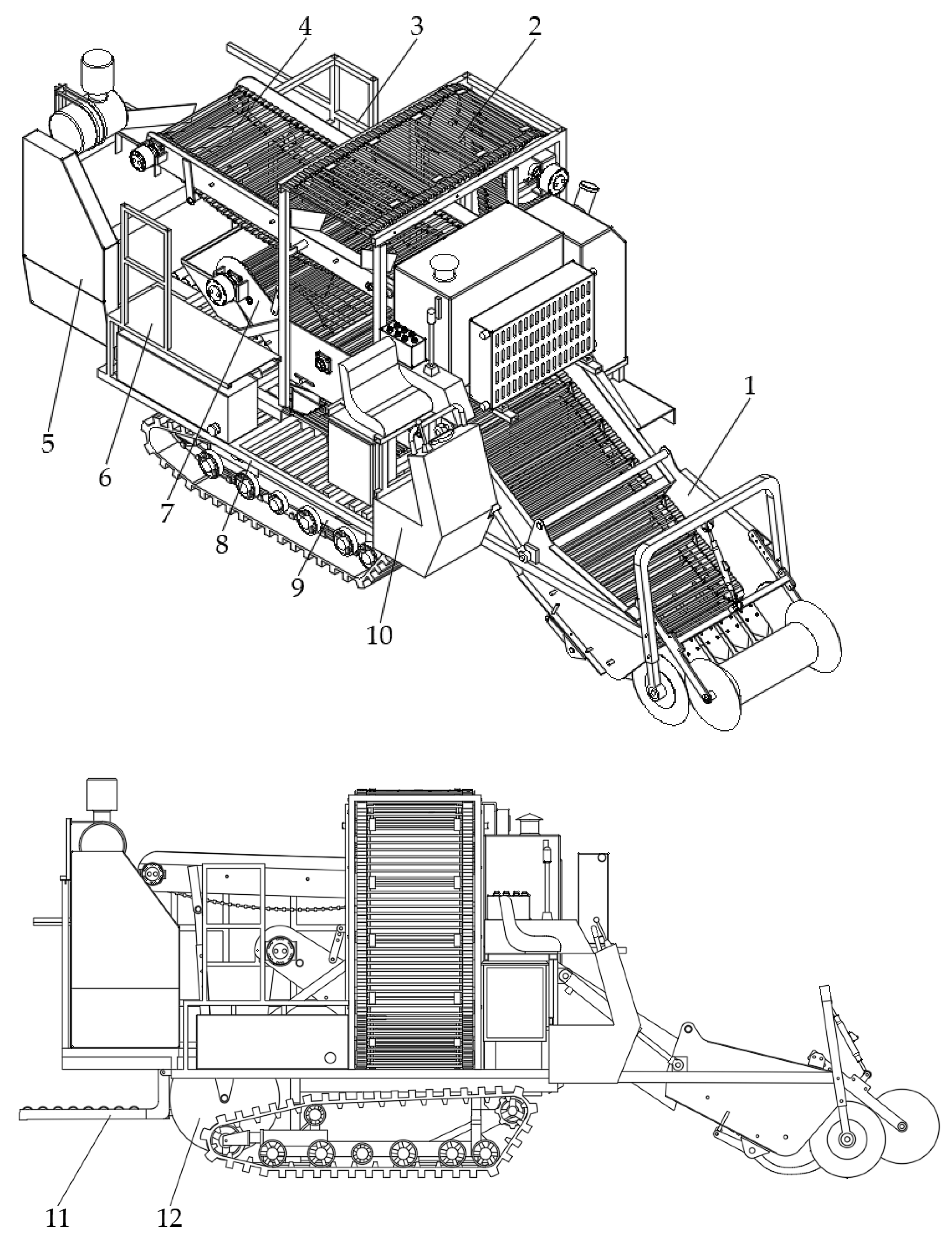
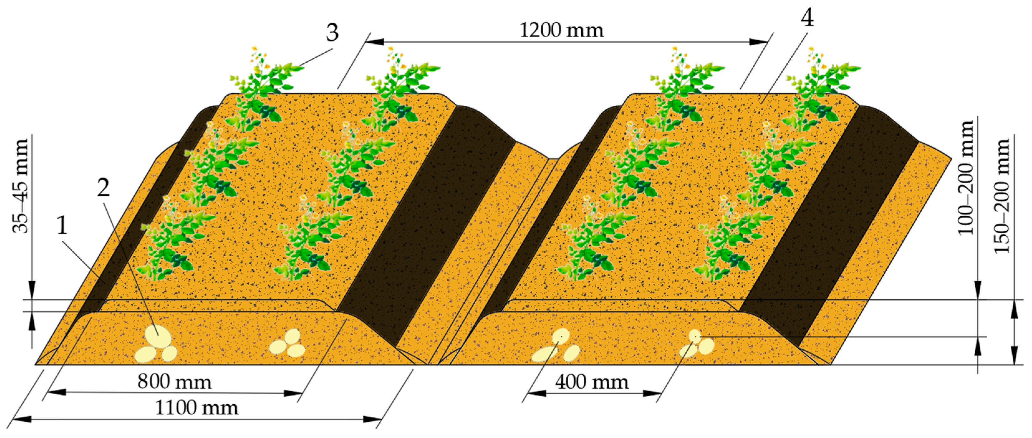
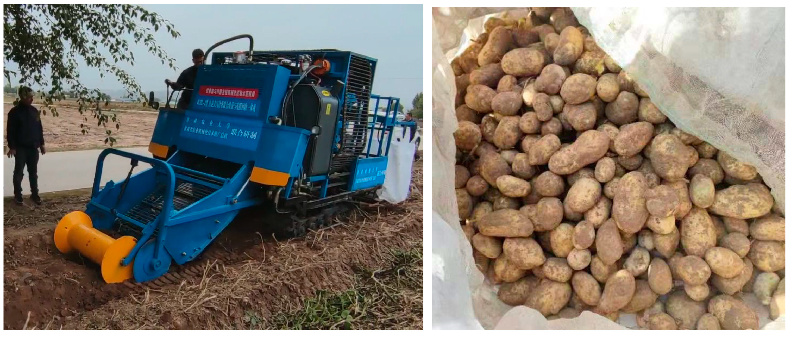
2. General Presentation of the Self-Propelled Machine for Combined Potato Harvesting and Residual Plastic Film Retrieval

In response to the abovementioned limitations, a self-propelled machine for combined potato harvesting and residual plastic film retrieval was designed, developed, and tested at Gansu Agricultural University. The machine is small, compact, and easy to operate and therefore particularly suitable for the planting mode of potato on large ridges with two rows per ridge and plastic film mulch covered with a layer of soil, as it is practiced in the hilly and mountainous areas of Northwest China.
The self-propelled machine for combined potato harvesting and residual plastic film retrieval (Figure 1 and Figure 2) is composed of a crawler chassis, a digging and lifting device, a potato–plastic-film separation device, a circulating and lifting device, a manual sorting platform, a residual-film collecting and bundling device, a ton-bag handling device, a transmission system, a hydraulic control system, and a frame. Its size and configuration meet the agronomic requirements of the potato planting mode on large ridges with two rows per ridge and plastic film mulch covered with soil, as is practiced in Gansu Province [31,32,33,34]. The machine employs a crawler chassis suitable for potato harvesting in small and medium plots that is able to perform tight turns and limit soil compaction during operation. The main technical parameters of the combined potato harvester are summarized in Table 1.
During operation, the profiling crushing roller of the digging and lifting device crushes the soil clods on the surface of the film and limits the digging depth of the machine, while the earth-cutting disc cuts the soil clods, vines, and weeds to prevent congestion and entanglement at the front end of the digging and lifting device. The digging shovel picks up the plastic film and potato mixture and transports it to the potato–plastic-film separation device via the lifting chain. The potato and soil are initially separated, and some soil pieces and debris are sieved off through the gaps in the lifting-chain bars through shaking and loosening. The potato–plastic-film separation device separates the plastic film from the potato tubers and further crushes and sieves off the large soil pieces. The plastic film is transported to the collecting device for rolling and bundling, while the potato and soil pieces that cannot pass through the gaps of the conveying chain rod fall into the circulating and lifting device. This further separates the potatoes from the soil pieces and lifts them to the manual sorting platform, where the unscreened soil pieces are screened out by hand by two to four operators. The conveyor screen transports the potatoes backward to the ton bag for collection, and the ton-bag handling device unloads the bag full of potatoes to the ground.

3. Design and Analysis of Main Systems of the Self-Propelled Machine for Combined Potato Harvesting and Residual Plastic Film Retrieval

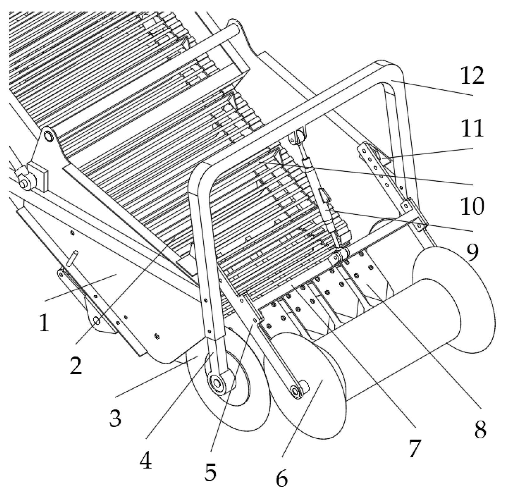
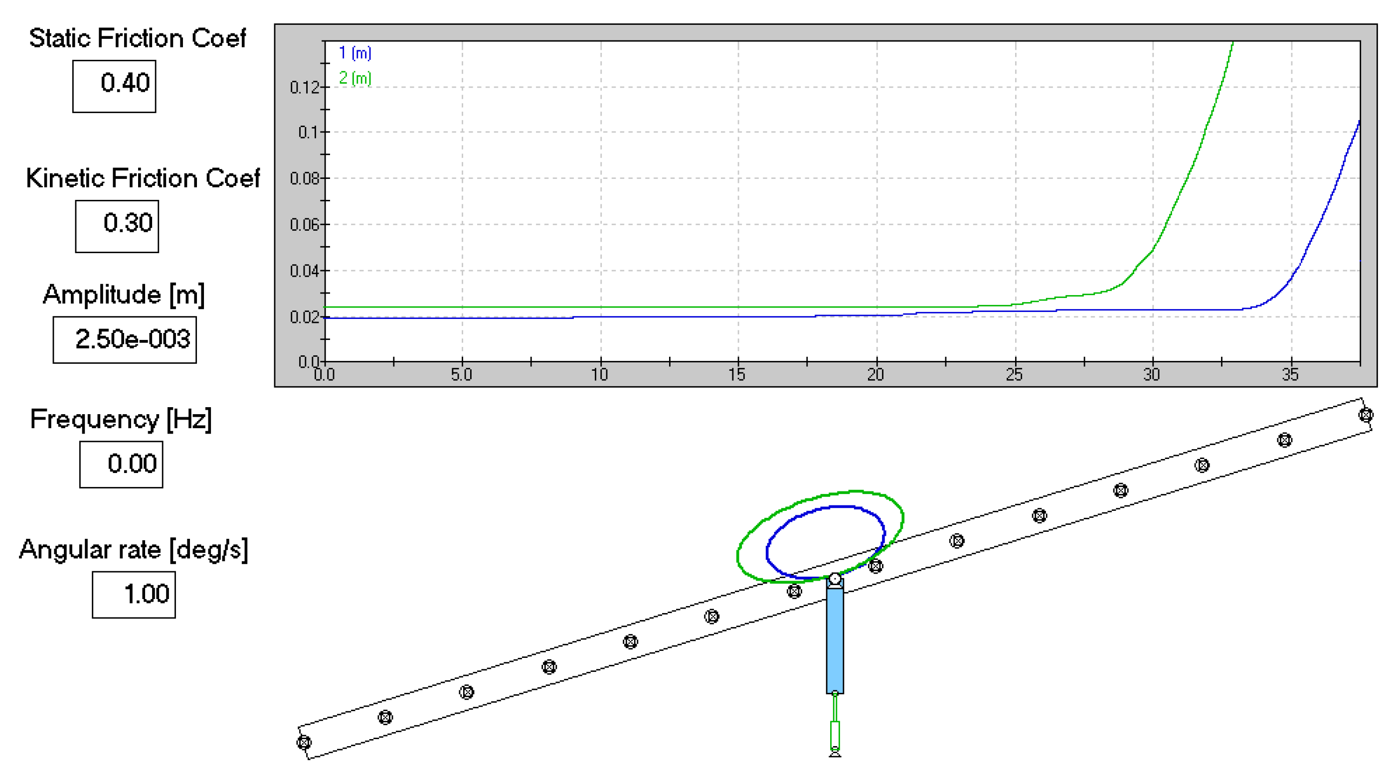
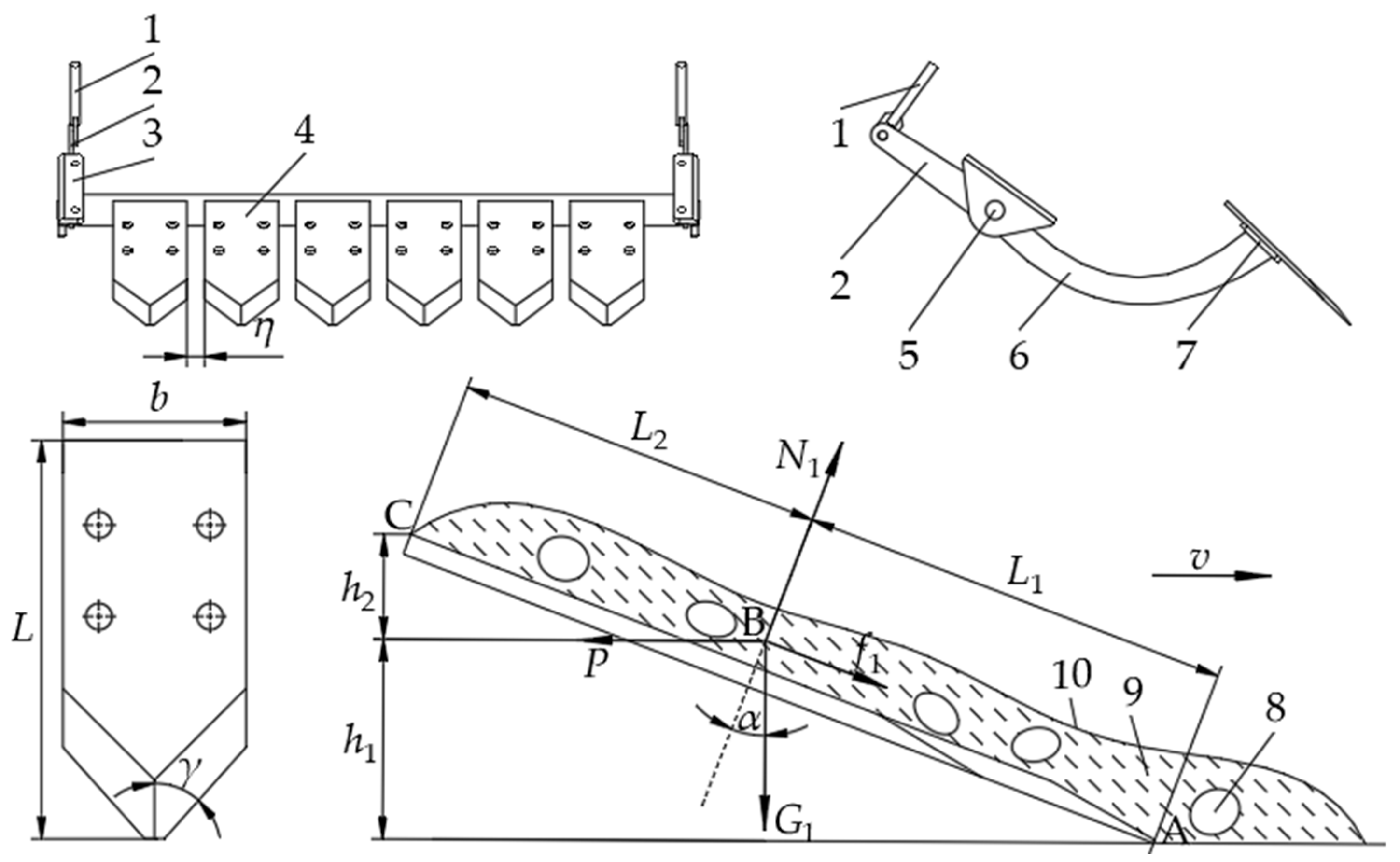
3.1. Digging and Lifting Device

The digging and lifting device serves to dig up the soil mixed with potatoes and plastic film and transport it to the separation device by means of the lifting chain. The main design objectives were reducing digging resistance, improving soil breaking capacity, and preventing soil congestion and the entanglement of vines, and weeds. The device shown in Figure 3 consists of a digging shovel, a mechanism for adjusting the angle of the shovel and digging depth, an earth-cutting disc, and a lifting chain.
The mechanism for adjusting the digging depth consists of a profiling crushing roller, a connecting plate, a connecting crossbar, a limiting pull rod, and a U-shaped connecting rod. The U-shaped connecting rod is welded to the front end of the side plate of the digging device, the ear plate is welded to the upper frame of the side plate of the digging device, the connecting plate is fixed by the connecting crossbar, the front mounting hole is hinged to the profiling crushing roller shaft, and the rear mounting hole is hinged to the ear plate. The limiting pull rod is hinged to the lugs on the connecting crossbar and the lugs of the U-shaped connecting rod. The profiling and crushing roller is similar in shape to the field ridge and serves to limit the digging depth of the machine in order to control the direction of the machine, prevent running off, and to break the soil clods on the plastic film mulch [35,36]. By changing the length of the limiting pull rod, the digging depth of the implement can be adjusted between 0 and 300 mm. The height-adjustable fixed earth-cutting discs are 500 mm in diameter with a thickness of 5 mm. The disks are installed on both sides of the profiling crushing roller, which can cut the solid soil blocks, potato vines and weeds, and prevent soil congestion and vine entanglement, which could interfere with the operation of the machine [37,38,39].
To reduce the overall length of the machine and improve its passing ability, the tilting angle (δ) of the digging and lifting device was designed to be adjustable up to 35°. Figure 4 and Figure 5 show a Working Model 2D [40] simulation of potatoes sliding along a smooth ramp and a lifting chain bar (either vibrating or not) for comparison, the angle (δ) of which is progressively increased from zero to more than 35°. The mass of the average-size potato was set to 80 g, and the mass of a large potato was set to 120 g. The static coefficient of friction between the potatoes and the lifting chain/smooth ramp was 0.4, and the kinetic coefficient of friction was 0.3 [41,42,43,44].
The Working Model 2D simulations show that the chain bar delays the sliding of the potatoes compared to a smooth incline. The simulations also show that the sliding of smaller potatoes is affected more by the vibration of the chain bar. This is because smaller potatoes may settle more easily and deeper between the bars of the chain transporter.
According to Figure 5, if the angle (δ) of the lifting chain is greater than 25°, the potatoes mixed with soil and plastic film may slide down along the lifting chain. This can lead to blockage of the front end of the device and impend the operation of the machine. To prevent this from happening, scrapers were welded to the lifting chain to transport the soil–potato–plastic film mixture smoothly backward. The scrapers are made of bent steel plates with a thickness of 5 mm, a length of 940 mm, and a height of 60 mm. In other potato harvesting machines, the pitch of the scraper is between 150 and 300 mm [36]. In the present design, 20 scrapers were welded on the lifting chain, and the pitch of the scrapers was set to 300 mm.
The digging parts include the digging shovel, the main frame of the shovel, and the mechanism for adjusting the angle of the shovel. Its function is to dig up the soil–potato–plastic film mixture and transport it to the lifting and separating device. The basic requirements for the design of the digging parts were: (1) to dig as little soil and debris as possible and to dig clean potato pieces while maintaining the desired digging depth; (2) to ensure the digging depth is stable and can be adjusted according to field conditions; (3) that the digging shovel should have strong soil breaking ability, particularly for clay and heavy soils, in order to provide favorable conditions for subsequent potato separation; (4) to avoid soil congestion and vine entanglement, the digging shovel is required to have self-cleaning abilities, doubled by low resistance to penetration; and (5) the sharpened edges should have good resistance to wear [36,39].
The machine implements a combined flat shovel with a working width of 1100 mm consisting of six individual shovels mounted on bending beams (see Figure 6). The shovel bracket is welded on the bending beam, and the bending beam and the limiting rod are attached with screws to the shovel shaft, forming the main frame of the shovel. In turn, the shovel is fixed to the shovel bracket using screws. During installation, it is necessary to ensure that the six individual shovels are in the same plane and that their tips are in line. In existing potato harvesting machines, the skid clearance between two adjacent shovels is between 30 and 40 mm [36]. In this design, the skid clearance between adjacent digging shovels is η = 33.5 mm, and the width of one digging shovel is b = 140 mm.
To ensure a good self-cleaning function, the bevel angle (γ) of the digging shovel should be [36,39,45]:
90 ° γ > φ
where φ is the friction angle of the soil–potato–plastic film mixture on the digging shovel (usually 30° < φ < 36°).
The smaller the bevel angle (γ) of the digging shovel, the stronger the cutting and sliding ability of the blade. However, when the angle (γ) is too small, the abrasion resistance is reduced, the potato loss rate is increased [3,13,18]. Thus, the range of bevel angle (γ) of the digging shovel should generally range from 40° to 50°. In the design of the self-propelled machine for combined potato harvesting and residual plastic film retrieval, a bevel angle of the digging shovel of γ = 42.5° was adopted.
Furthermore, it is required that the digging shovel be able to easily cut the soil ridge and smoothly transport the dug-out soil–potato–plastic film mixture to the back end of the lifting chain.
The following equations were established based on analysis of the force condition of the soil–potato–plastic film mixture on the shovel surface (Figure 6) [36,45,46]:
{ P cos α f 1 G 1 sin α = 0 N 1 G 1 cos α P sin α = 0
where:
f 1 = μ 1 N 1
and where P is the force required to move the soil–potato–plastic film mixture along the digging shovel (N), f1 is the friction force between the surface of the shovel and the soil–potato–plastic film mixture (N), μ1 is the friction coefficient between the surface of the shovel and the soil–potato–plastic film mixture (μ1 = tan φ), G1 is the weight of the soil–potato–plastic film mixture (N), N1 is the normal reaction force acting between the digging shovel and the soil–potato–plastic film mixture (N), and α is the titling angle of the shovel in degrees.
The following formula is derived from Equations (2) and (3):
α = arctan P μ 1 G μ 1 P + G
which reveals that small titling angles (α) of the digging shovel are associated with a reduced digging resistance (P), making it easy to dig through soils with poor breakability. In the adopted design, the hanger plate is fixed by the lower frame of the side plate of the digging device, the frame of the digging shovel is hinged to the center hole of the hanger plate, the adjusting screw is hinged to the limiting lever at one end, and the other end is connected to the lower frame of the side plate of the digging device with a nut, which, together, form the angle adjustment mechanism of the digging shovel. The nut of the adjusting screw allows the titling angle (α) of the digging shovel to be changed from 15° to 25° according to the working conditions of the machine.
As shown in Figure 6, the length (L) of the digging shovel is divided into L1 and L2. The length of the front section of the digging shovel (L1) can be expressed by the titling angle (α) and the average digging depth (h1) of the digging shovel according to the following equation:
L 1 = h 1 sin α
The minimum length of the back section of the digging shovel (L2) can be calculated based on kinetic energy considerations (see Figure 6). The dug-out soil–potato–plastic film mixture, which is assumed to be incompressible, moves along the shovel surface at a speed (v) equal to the velocity of the machine. The kinetic energy at point B of the dug-out soil–potato–plastic film mixture is:
E = m v 2 2
where m is the mass of the soil–potato–plastic film mixture on the shovel surface (kg).
The mixture continues to move along the shovel surface up to point C at the end of the shovel, where it suddenly loses speed (vc = 0). The soil–potato–plastic film mixture then begins to expand, accumulate, and spread out to both sides of the shovel, and the potato tubers are gradually revealed. Most of the kinetic energy of the dug-out soil–potato–plastic film mixture at point B is spent to overcome the work (Wf) done by the frictional force (f2) through the length (L2) from B to C on the shovel surface and the work (Wω) done to lifting the dug-up soil–potato–plastic film mixture by h2. Then, the following equations can be written:
W f = G 1 L 2 tan φ cos α
W ω = G 1 L 2 sin α
where h2 is the height of the back section of the digging shovel in meters.
The energy conservation equation of the dug-out soil–potato–plastic film mixture from B to C of the shovel surface yields:
1 2 m v 2 = W f + W ω = m g L 2 tan φ cos α + m g L 2 sin α
This equation can be reduced to:
L 2 = v 2 cos φ 2 g sin ( α + φ )
The full length of the digging shovel can then be calculated as:
L = h 1 sin α + v 2 cos φ 2 g sin ( α + φ )
According to Equation (11), the length of the digging shovel is 320–400 mm when the angle (α) is 14° to 25°. Smaller values are applicable to sandy soils, and higher values are applicable to medium firm soils [36,39]. For the anticipated operating conditions and technical parameters of the machine (Table 1) and for loessal working soil, the total length of the digging shovel was set to L = 330 mm.
The linear speed of the lifting chain influences the soil and potato separation capacity of the digging and lifting device. To improve this separation capacity and to make potato transport smoother, the ratio (λ) between the operating speed of the machine (v) and the linear speed of the lifting chain (v1) should be in the range of [18,47]:
λ = v 1 v = 0.8 ~ 2.5
To ensure the operation efficiency and harvest quality of the potato harvester, the linear speed of the lifting chain (v1) should be slightly greater than the operating speed (v) of the implement [48]. Practice shows that the soil and potato separation efficiency is inversely proportional to the linear speed of the lifting chain, and the soil–potato separation efficiency is higher when the linear speed is between 1.1 and 1.8 m/s [47]. A suitable linear speed of the first lifting chain of the combine harvester is assumed to be between 1.5 and 2.0 m/s [36]. Therefore, the linear speed of the lifting chain (v1) of the digging and lifting device was set to 1.5 m/s.

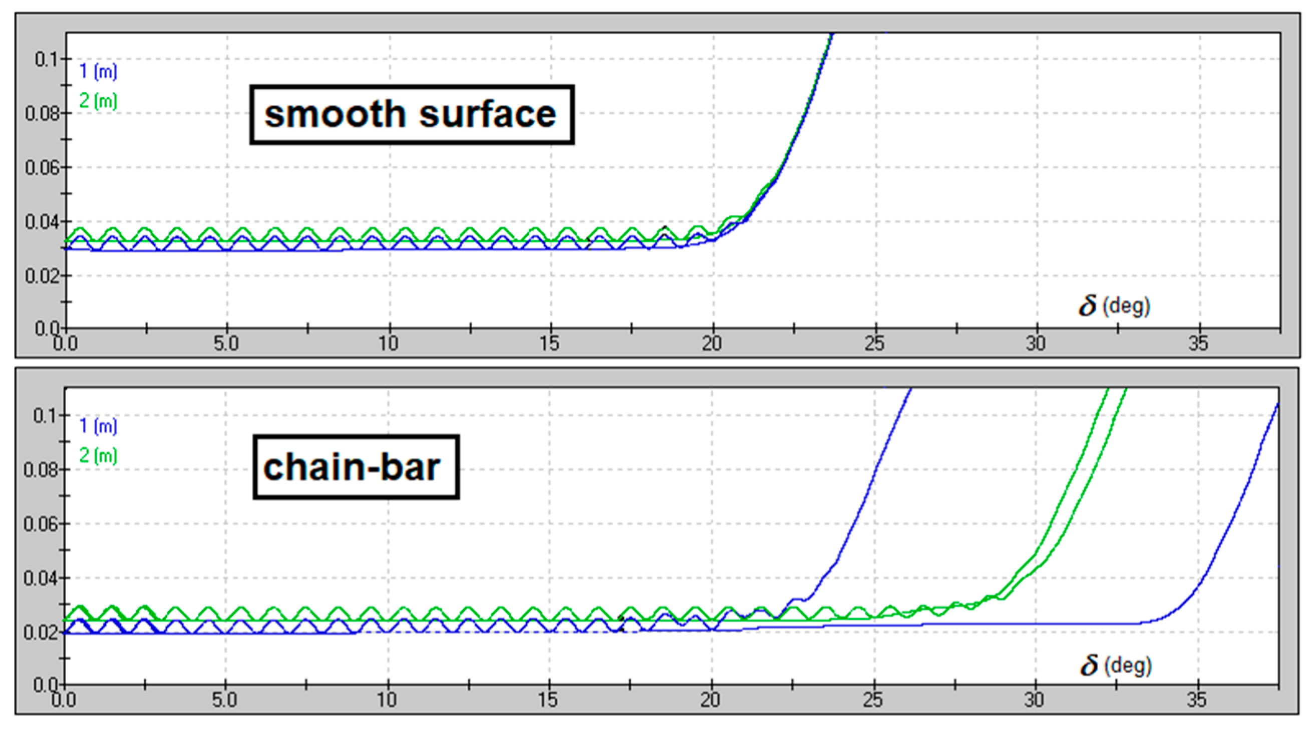
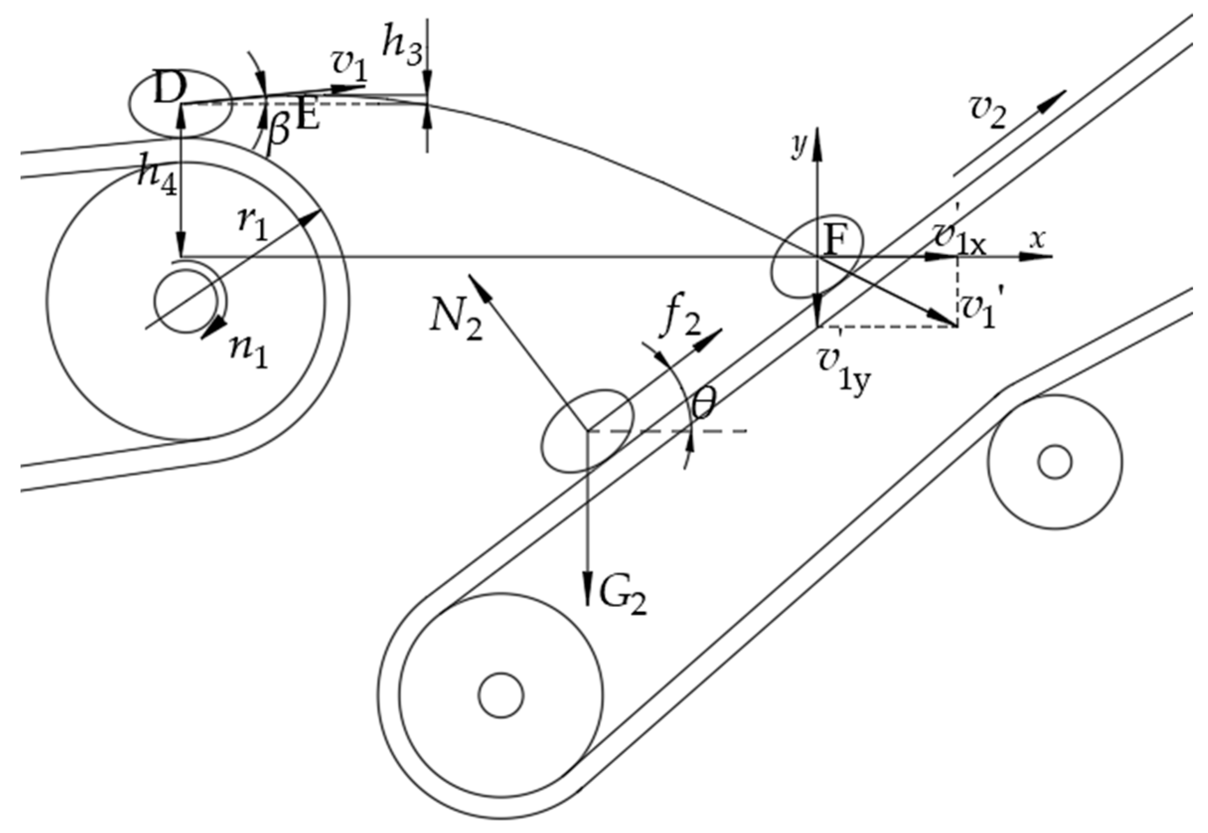
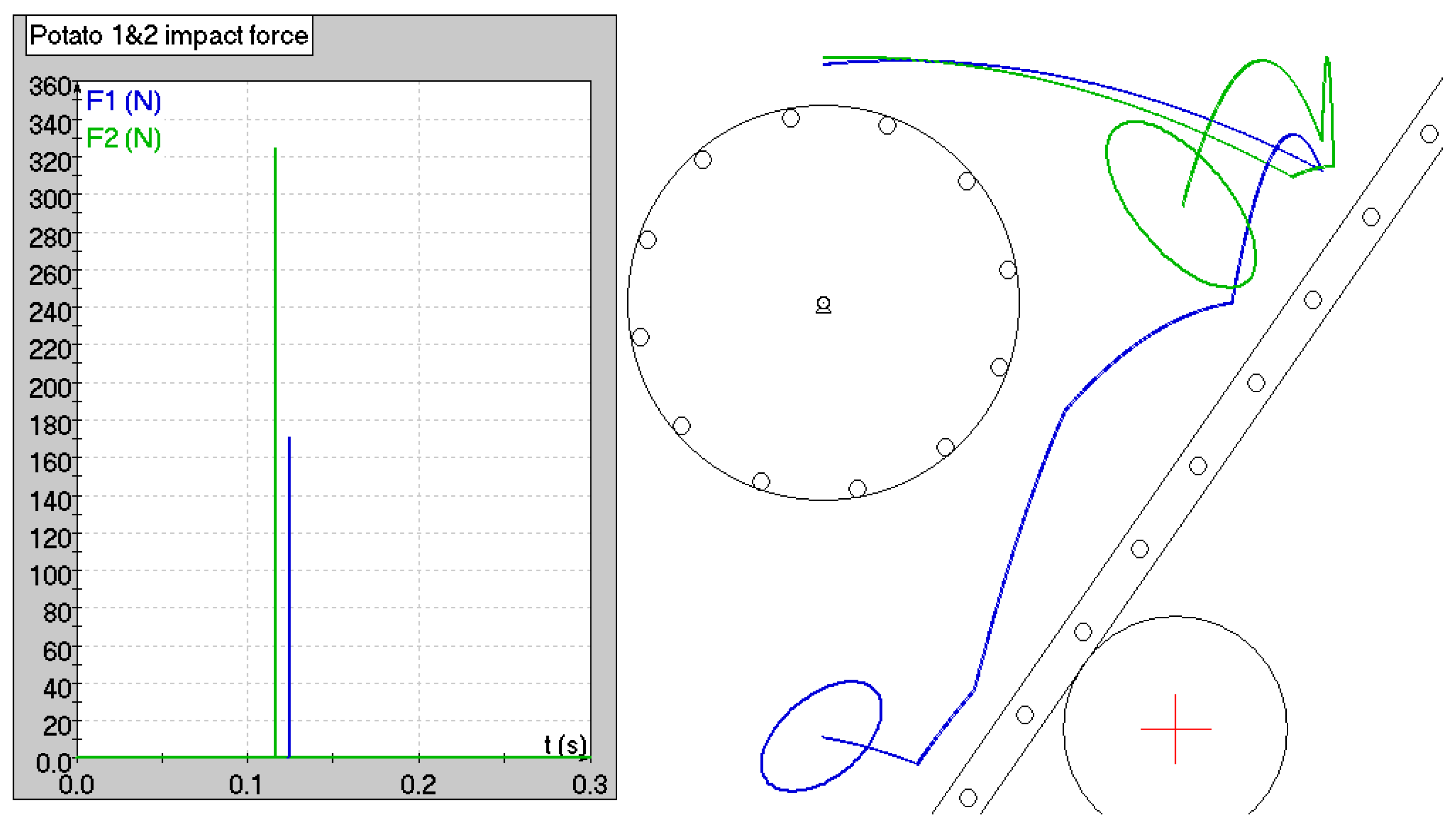
3.2. Design and Analysis of the Potato–Plastic-Film Separation Device

The friction coefficients between potatoes and the conveyor chain and between residual plastic film and the conveyor chain are different. Therefore, the potato–plastic-film separation device can separate potatoes from residual plastic film [36] and continue to transport the screened residual plastic film backward to the collecting device of rolled and bundled plastic film, while the screened potatoes fall into the circulation lift device below the machine.
First, the force that potatoes can experience on the potato–plastic-film separation device was analyzed, (see Figure 7). To separate potatoes from plastic film, potatoes cannot be transported upward with the conveying chain, so the friction force experienced by potatoes (f2) is upward along the conveying chain and less than the gravitational force experienced by potatoes along the conveying chain:
G 2 sin θ > μ 2 G 2 cos θ
To successfully separate potatoes from plastic film, the angle (θ) between the potato–plastic-film separation device and the ground should be:
μ 2 < tan θ
In the above two equations, G2 is the weight of the potato in Newtons, and μ2 is the coefficient of friction between the potatoes and the conveyor chain.
A kinematic analysis of the process of potatoes dropping down from the end of the lifting chain of the digging and lifting device to the potato–plastic-film separation device was also carried out, as shown in Figure 7. Point D is the release point of the potato at the lifting chain of the digging–lifting device, point E is the highest moving point of potatoes after being thrown, and point F is the impact point between the potato and the conveying chain rod of the potato–plastic-film separation device.
As the friction coefficients between potatoes, residual plastic film, and the conveyor chain varies, the angle (θ) between the potato–plastic-film separation device and the ground should be adjustable to achieve the best separation of the potatoes from the plastic film. The self-propelled machine for combined potato harvesting and residual plastic film retrieval allows this angle to be changed from 40° to 55°. The linear speed of the conveying chain (v2) also has an effect on the potato and plastic film separation. When the linear speed is too high, the potatoes will roll rapidly or fly out of the conveying chain and get damaged. When the speed (v2) is too low, the soil–potato–plastic film mixture conveyed by the digging and lifting device accumulates on the conveying chain of the potato–plastic-film separation device, affecting potato–plastic-film separation. Based on experiments, the linear speed of the conveying chain of potato–plastic-film separation device was set to v2 = 0.6 m/s.
At point D, where potatoes leave the lifting chain, their speed equals the linear speed of the lifting chain (v1):
v 1 = 2 π n 1 r 1 60
where n1 is the rotational speed of the driving wheel of the lifting chain (r/min), and r1 is the pitch radius of the main wheel of the lifting chain of the digging and lifting device (m). The direction of the velocity vector (v1) relative to the horizontal direction is measured by angle β, as shown in Figure 7.
After it separates at point D, the potato reaches the highest point on its trajectory at point E and impacts the conveying chain bar at point F. The maximum height (h3) of the trajectory of the potato can be calculated as:
h 3 = v 1 2 sin 2 β 2 g
where g is the acceleration due to gravity (g = 9.82 m/s2).
The time it takes the potato to move from the highest point (E) to the impact point (F) with the conveyor chain bar is:
t 1 = 2 ( h 3 + h 4 ) g
where h4 is the falling height of potatoes thrown out from the end of the lifting chain of the digging and lifting device in meters (see Figure 7).
The horizontal and vertical components of the velocity of the potato at the collision point (F) with the conveying chain rod of the potato–plastic-film separation device are:
v 1 x = v 1 cos β
v 1 y = 2 g ( h 3 + h 4 )
Therefore, the magnitude of the impact velocity of the potato at point F is:
v 1 = v 1 2 cos 2 β + 2 g ( h 3 + h 4 )
The force with which the potato impacts the second conveying chain rod depends on the mass of the potato, the coefficient of restitution, and whether the potato impacts one rod centrically (i.e., the center of mass of the potato is aligned with the centroid of the conveyor rod) or offset. Because time t1 in Equation (17) decreases, for larger angles (θ), the impact velocity is decreased, as well as the impact force between the potato and the conveyor rods. Figure 8 is a Working Model 2D [40] simulation the impact between two potatoes of average and large size and the conveyor of the potato–plastic-film separation device, confirming this assumption. The masses of the two potatoes were 80 and 120 g, respectively; the static coefficient of friction was 0.44; the kinetic coefficient of friction was 0.269; and the coefficient of restitution was 0.525 [41,42,43,44].

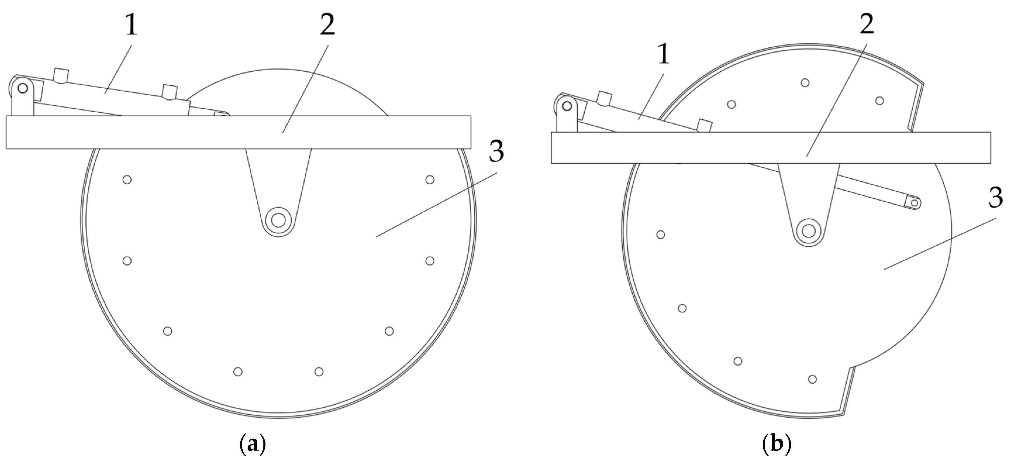
3.3. Design and Analysis of the Residual-Film Collecting and Bundling Device

The residual-film collecting and bundling device (see Figure 9a) consists of plastic-film rolling rollers, drive chains, roller sprockets, input sprockets, and rotating shafts. The roller sprockets and the central input sprocket are driven by a chain, and together, they rotate in the same direction.
The residual plastic film is transported to the collecting device via the potato–plastic-film separation device.
Figure 9b shows the operation principle of the residual-film collecting and bundling device, where v2 is the linear speed of the conveying chain of the potato–plastic-film separation device, D1 is the diameter of the circle formed by the plastic film rolling rollers, D is the maximum diameter of the residual plastic film bundle, and d is the outer diameter of one plastic film rolling roller.
The side plate of the residual-film collecting and bundling device is equipped with eight rollers with a length of 630 mm and a diameter of d = 128 mm. To avoid winding of the residual plastic film, the rollers used to roll the plastic film are fitted with four longitudinal veins. The plastic film rolling rollers envelope a cylinder with a diameter of D1 = 570 mm, while the collected residual plastic film bale can have a maximum diameter of D = 506 mm. All eight plastic-film rolling rollers rotate in the clockwise direction, causing the bale of residual plastic film to rotate in the counterclockwise direction. When the bale reaches a certain height as it is driven by the eight rollers, its ascending speed reaches zero, then falls back due to gravity. The debris separating from the residual plastic film is sieved off through the gap between the rollers, reducing their amount in the residual plastic film bundle.
As shown in Figure 10b, when the residual plastic film is collected, the hydraulic rod extends and pushes the residual-film collecting and bundling device to rotate and unload the bundled residual plastic film onto the field.

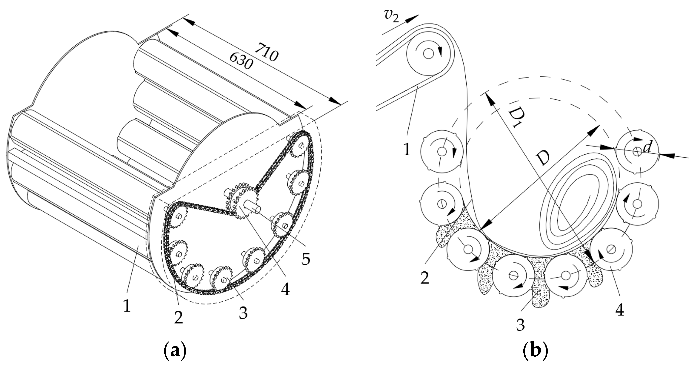
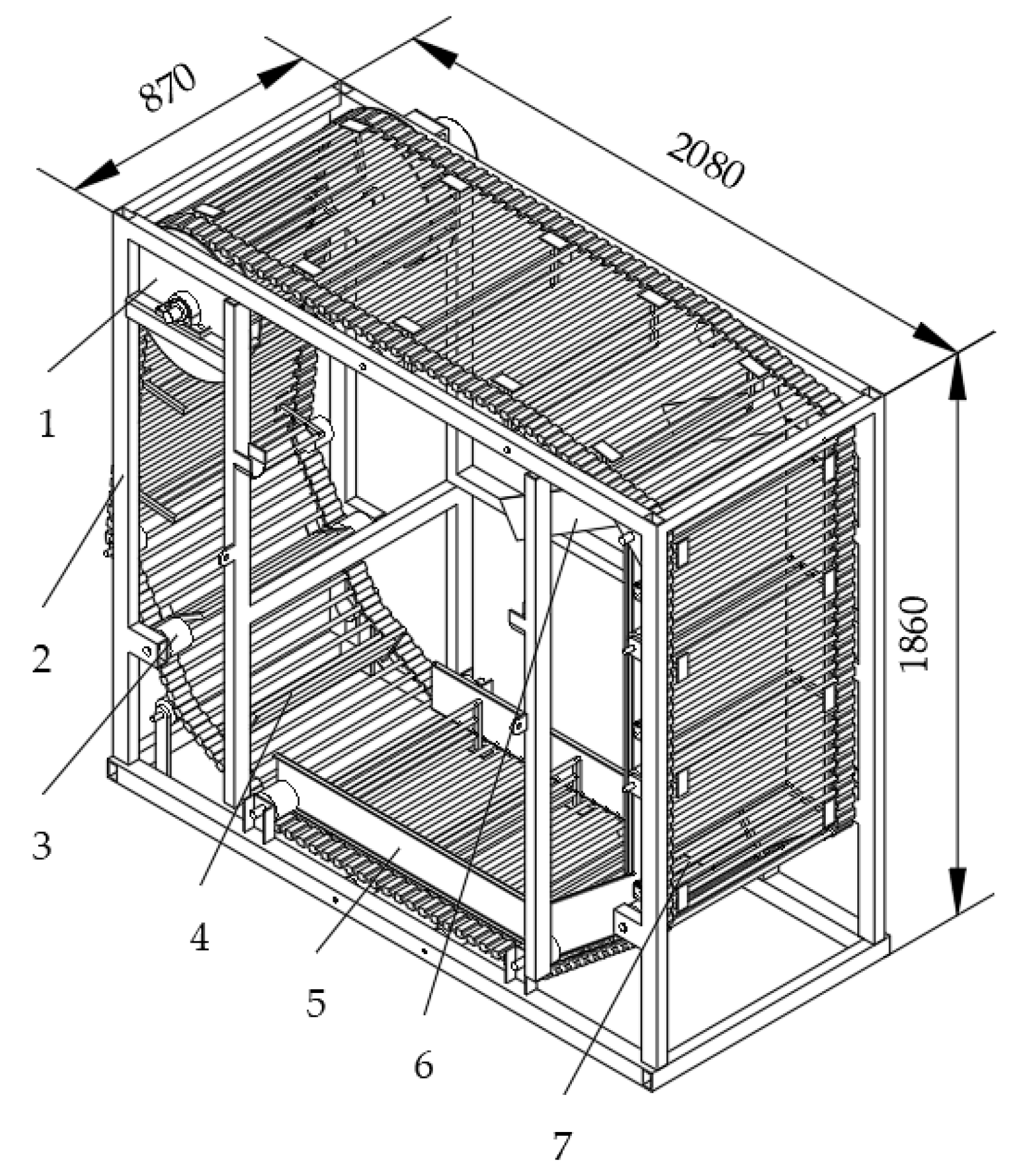
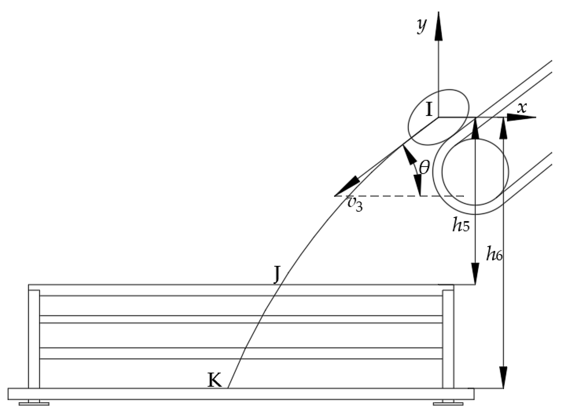
3.4. Design and Analysis of the Circulating and Lifting Device

The circulating and lifting device is installed in the front of the potato–plastic-film separating device and serves to lift the potatoes after being screened by the separating device (see Figure 11). It consists of a bracket, driving wheel, guiding carrier pulley, lifting screen, lifting scraper, baffle, and potato slide plate. The lifting screen and lifting scraper are treated with rubber coating to prevent potato damage as they are moved upward.
The circulating and lifting device is divided into the receiving section, lifting section, and unloading section [49]. In the receiving section, potatoes fall from the front of the potato–plastic-film separation device at a certain speed onto the lifting screen of the circulating and lifting device. In this section, the potatoes must accurately fall into the gap of the lifting scraper that is installed in the lifting screen without being damaged, while at the same time, debris is sieved. In the lifting section, potatoes must be transported smoothly, while in the unloading section, potatoes must slide smoothly onto the conveyor chain of the manual sorting platform.
Figure 12 shows a schematic diagram of the receiving section of the circulating and lifting device. The motion of potatoes falling from the lower end of the conveying chain of the potato–plastic-film separation device to the lifting screen of the circulating and lifting device is an oblique downward motion with an initial velocity (v3).
In Figure 12, point I is the position of the center of mass of the potato when at the lower end of the potato–plastic-film separation device. Point J is the intersection of the potato’s trajectory and the upper end of the lifting scraper after the potato is thrown, and point K is the impact point between the potato and the lifting-screen rod of the circulating and lifting device. For a fixed reference frame with its origin at point I (Figure 12), the equations of motion of the center of mass of the potato are:
{ x = v 3 t 2 cos θ y = v 3 t 2 sin θ 1 2 g t 2 2
where v3 is the velocity of potatoes at point I. Equation (21) yields the time required for the potato to travel from point I to point J:
t 3 = v 3 2 sin 2 θ + 2 g h 5 v 3 sin θ g
The time required to travel from point I to point K is expressed as:
t 4 = v 3 2 sin 2 θ + 2 g h 6 v 3 sin θ g
where h5 is the vertical distance between point I and point J (m), and h6 is the vertical distance between point I and point K (m) (see Figure 12). Consequently, the time it takes for the potato to travel from point J to point K is expressed as:
t 5 = t 4 t 3 = v 3 2 sin 2 θ + 2 g h 6 g v 3 2 sin 2 θ + 2 g h 5 g
S is the pitch of the lifting scraper, and v4 is the linear speed of the lifting screen of the circulating and lifting device, and the time it takes for the lifting scraper to move from one pitch to another is expressed as:
t 6 = S v 4
Time t6 in Equation (25) should be longer than time t5 in Equation (24). Therefore, the linear speed of the lifting screen of the circulating and lifting device must be:
v 4 S L 3 t 5
where L3 is the maximum possible length of a potato tuber. The maximum linear speed of the lifting screen was set to v4 = 2.0 m/s, and a total of 19 lifting scrapers were installed on the lifting screen, spaced at S = 370 mm.
When the lifting scraper moves to the upper end of the circulating and lifting device, potatoes are thrown to the potato slide plate to slide into the manual sorting platform. This unloading process corresponds the force diagram presented in Figure 13, where G3 is the weight of the potatoes carried by the lifting scraper, N3 is the supporting force of the lifting scraper on the potato, f3 is the friction between the potato and the lifting scraper, and ψ is the included angle between the lifting scraper and the horizontal plane at the tangential point of the guide support wheel at the upper end of the circulating and lifting device.

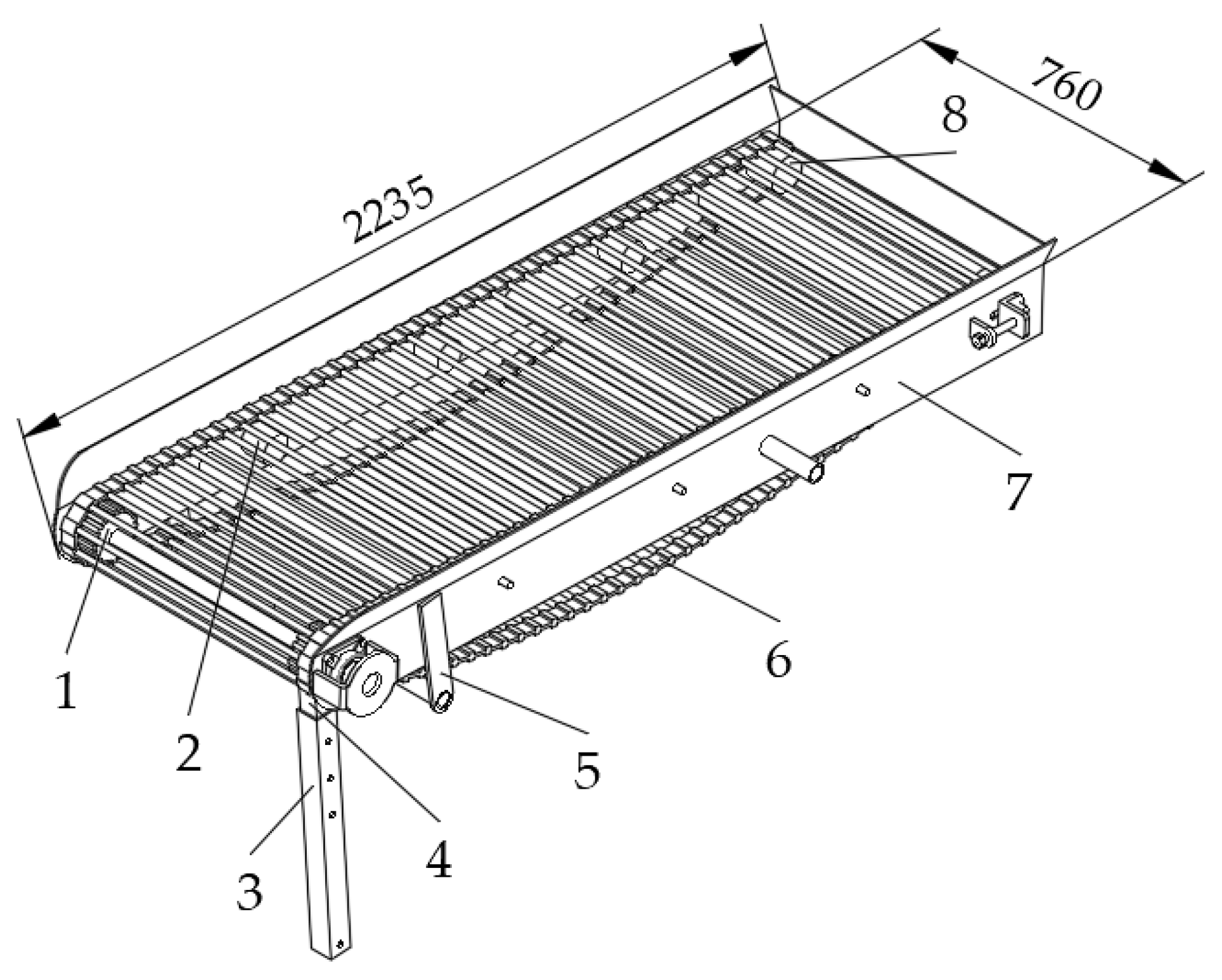
3.5. Design of the Manual Sorting Platform

The manual sorting platform (Figure 14) is used to transport the potatoes delivered by the circulating and lifting device backward. The main components of the device include a side plate, driving wheel, guiding wheel, supporting wheel, conveying screen, connecting frame, height-adjusting rod, and height-adjusting rod sleeve. The bar in the conveying screen is covered with rubber in order to limit potato injury. There are stations on both sides of the manual sorting platform, where manual workers can sieve the soil, stones, and other debris that has not been removed during the process of transporting the potatoes to the ton-bag handling device. Based on ergonomics considerations, the speed (v5) of the conveyor screen is set to 0.3 m/s [36]. The width of the sorting platform is 760 mm, and its angle and height can be adjusted by means of the height-adjusting rod and its sleeve noted as 3 and 4, respectively, in Figure 14.

4. Field Test Method and Test Results

In October 2021, field tests of the self-propelled machine for combined potato harvesting and residual plastic film retrieval were conducted in Xiangquan town, Dingxi city, Gansu Province. The specific conditions of the test were adopted in accordance with industry standard GB/T5262-2008 [50]. The test field was planted in large ridges with two rows per ridge and with covering soil on top of the plastic film mulch. The potato variety planted was LongShu No. 10, the space between rows was 400 mm, and the depth at which potato was planted was between 100 and 200 mm. The width of the bottom and the top of the ridge was 1100 mm and 800 mm, respectively; the height of the ridge was between 150 and 200 mm; and the distance between ridges was 1200 mm (see Figure 15). The type of soil was loessal with a moisture rate of 15.8%. The width of the plastic film was 1200 mm, and the film thickness was 0.01 mm. The thickness of the soil covering the plastic film ranged between 35 and 45 mm. Seedling killing treatment was carried out before the performance test.
In accordance with standards NY/T 648-2015 [51] and NY/T 1227-2019 [52], the harvesting performance and residual plastic film collection performance of the self-propelled machine for combined potato harvesting and residual plastic film retrieval were tested in the field with a large ridge and double-row configuration, with soil covering the top of the plastic film (Figure 16). The harvesting performance and residual plastic film collection abilities of the self-propelled machine for combined potato harvesting and residual plastic film retrieval were estimated based on the six following indices: potato loss rate, potato damage rate, potato impurity rate, potato bruising rate, residual plastic film pickup rate, and work productivity.
Besides, the working conditions of the digging and lifting device, the potato–plastic-film separation device, residual-film collecting and bundling device, circulating and lifting device, manual sorting platform, ton-bag handling device, transmission system, and hydraulic operating system were also observed.
The test plot was specified with a single ridge width, and the interval length of the measurement was 30 m. The test plot was randomly selected in the test field for potato harvesting and residual plastic film retrieval. The test was repeated 10 times, and the test results were reported as the average of the measured indices of these 10 tests. The potato loss rate, potato damage rate, potato impurity rate, potato bruising rate, work productivity, and residual plastic film pickup rate were calculated according to NY/T 648-2015 as follows [51].
T 1 = Q 1 + Q 2 Q × 100 %
T 2 = Q 3 Q × 100 %
T 3 = Q 5 Q 5 + Q 4 × 100 %
T 4 = Q 6 Q × 100 %
E c = Q c b T c
where
Q = Q 1 + Q 2 + Q 4
In the above equations, T1 is the potato loss rate (%), T2 is the potato damage rate (%), T3 is the potato impurity rate (%), T4 is the potato bruising rate (%), Q1 is the mass of unpicked potatoes (kg), Q2 is the mass of unearthed potatoes (kg), Q3 is the mass of injured potatoes (kg), Q4 is the mass of harvested potatoes (kg), Q is the total mass of potatoes (kg), Q5 is the mass of impurities (kg), Q6 is mass of potatoes with broken skin (kg), Ec is the working hour productivity (ha/h), Qcb is the amount of shift work during reliability assessment (ha), and Tc is the working time of the shift at the time of assessment (h).
During the test, a quality method was used to calculate the residual plastic film pickup rate as follows. The residual plastic film that had not been collected on the surface of the ridge was cleaned and dried, and its weight was measured using a precision scale. The total mass of the plastic film covered in the test plot before the operation was replaced by the total mass of new plastic film of the same type and length [52]. The residual plastic film pickup rate (c) was finally calculated as:
c = ( 1 W W 0 ) × 100 %
where W is total mass of film mulch left in the field, and W0 is total mass of plastic mulch present in the test plot before operation.

5. Analysis of the Field Test Results

Table 2 summarizes the test results when the machine was driven at 0.5 m/s, the lifting chain of the digging and lifting device had a linear speed of 1.5 m/s, the titling angle of the separating sieve of the potato–plastic-film separation device was 50°, its linear speed was 0.6 m/s, and the linear speed of the lifting screen of the circulating and lifting device was 0.7 m/s.
Table 2 shows that both the potato harvesting performance and the residual plastic film collection performance meet the national and industry standard requirements. Additional field tests show that all the parts of the machine function normally. Compared with other equipment with similar functions, the self-propelled machine for combined potato harvesting and residual plastic film retrieval performs better in separating potatoes from debris and plastic film and has a higher production efficiency of 0.12 ha/h. Overall, the machine helped to reduce manual operation and improve working efficiency.
However, we observed that the lower potato rhizome after killing the seedlings affects the separation and collection of the residual plastic film because it can enter the residual-film collecting and bundling device, while the seedlings mixed in with the potatoes are removed by workers at the manual sorting platform to ensure the quality of the collected potatoes. Since the performance results (T3) calculated with Equation (29) depend on the operating speed of the machine, this parameter affects the ability of the manual sorting platform workers to sort out impurities.

6. Discussion

The potato harvester presented in this paper is more compact than existing self-propelled potato combine harvesters [53,54,55], as well as tractor-based potato harvesters and residual plastic mulch film retrievers [31,34,56]. These qualities make it suitable for farming on small plots of land, while its tracked chassis allows for improved adaptation to the terrain conditions of hilly and mountainous areas. The results of the field tests show that all performance indicators meet national industry standard requirements. To further reduce mechanical damage to the potatoes and improve the quality of the potato harvest and the plastic film pickup rate, it is necessary to improve the design of the plastic film recovery device and to implement a potato buffer device. It is also necessary to identify the optimum combination of operating parameters of the machine.
At present, two to four workers placed on both sides of the manual sorting platform must perform occasional residual soil and film removal. Additional research on the mechanism of potato–soil separation [57,58] and on improving the potato–soil separation device [59,60,61] is planned. Adding sensors, cameras, and the necessary software [62,63,64] can further increase the degree of automation of the machine and reduce the labor intensity of the workers and of the machine operator.

7. Conclusions

In this paper, we presented a self-propelled machine for combined potato harvesting and residual plastic film mulch retrieval. The machine is capable of simultaneously performing potato digging, potato separation from soil and plastic film, potato collection and bagging, and residual plastic film retrieval. The main systems of the machine were designed and calculated, and a physical prototype was built. Field tests show that the self-propelled machine for combined potato harvesting and residual plastic film retrieval meets current industry standards for potato loss rate, damage rate, bruising rate, and impurity rate, as well as residual plastic film collection rate. It was also proven that the reduced size of the machine allows for a small turning radius compared to other existing potato harvesters. This study provides a solution to the problem of harvesting potatoes from small and medium-sized plots in hilly and mountainous regions of Northwest China, as well as a reference for the development of similar self-propelled potato combine harvesters applicable elsewhere in the world.

Author Contributions

Conceptualization, W.S. and X.L.; software, Y.J. and P.A.S.; investigation, Y.J., W.S., Z.Z., H.W. and X.L.; resources, W.S. and P.A.S.; writing—original draft preparation, Y.J.; writing—review and editing, W.S., P.A.S., X.L., H.Z., H.L. and Y.J.; supervision, Z.Z., H.W., X.L., H.Z., H.L. and P.A.S.; project administration, W.S.; funding acquisition, W.S. All authors have read and agreed to the published version of the manuscript.

Funding

This research was funded by the Key Scientific and Technological Program of Gansu Province (22ZD6NA046), the Gansu Provincial University Industry Support Plan (2022CYZC-42), and the 2022 Gansu Province Excellent Graduate Student “Innovation Star” Project (2022CXZX-640).

Institutional Review Board Statement

Not applicable.

Informed Consent Statement

Not applicable.

Data Availability Statement

Data are reported within the article.

Conflicts of Interest

The authors declare no conflict of interest.

References

  1. Wei, Z.; Li, H.; Sun, C.; Li, X.; Liu, W.; Su, G.; Wang, F. Improvement of potato harvester with two segment of vibration and wave separation. Trans. Chin. Soc. Agric. Eng. 2018, 34, 42–52. [Google Scholar]
  2. Wei, Z.; Li, H.; Su, G.; Sun, C.; Liu, W.; Li, X. Development of potato harvester with buffer type potato-impurity separation sieve. Trans. Chin. Soc. Agric. Eng. 2019, 35, 1–11. [Google Scholar]
  3. Wang, H.; Zhang, Z.; Issa, I.I.M.; Xie, K.; EL-Kolaly, W.; Cao, Q. Design and experiment of small-sized potato harvester suitable for hilly and mountainous areas. Acta Agric. Zhejiangensis 2021, 33, 724–738. [Google Scholar]
  4. Kang, H.; Liu, M.; Wang, L.; Wei, M.; Liu, J.; Zhou, J.; Zhang, S. Simulation analysis of separating and conveying device of potato harvester based on EDEM. J. Agric. Mech. Res. 2022, 44, 1–8+16. [Google Scholar]
  5. China’s Potato Cultivation Area Reached 70 Million Mu Western Main Production Areas Accounted for More than 80%. Available online: www.chinanews.com.cn/cj/2021/10-11/9583694.shtml (accessed on 10 March 2023).
  6. China’s Potato Planting Area Exceeds 70 Million, Mu. Available online: www.bjnews.com.cn/feature/2020/09/25/772785.html (accessed on 10 March 2023).
  7. Chen, W.; Zhu, J.; Chen, X.; Yuan, D.; Yao, K.; Peng, Z. The current situation of the development of agricultural mechanization of slope—Farmland in our country. J. Agric. Mech. Res. 2017, 39, 1–5. [Google Scholar]
  8. Yang, X.; Wei, H.; Zhao, W.; Jiang, Y.; Dai, L.; Huang, X. Design and experiment of 4U-1600 set of pile type potato digger. Trans. Chin. Soc. Agric. Mach. 2020, 51, 83–92. [Google Scholar]
  9. Liu, C.; Hu, J.; Zhao, S.; Sha, L.; Yu, Z. Research progress on potato harvesting equipments. J. Chin. Agric. Mech. 2019, 40, 31–35, 124. [Google Scholar]
  10. Dou, Q.; Sun, Y.; Sun, Y.; Shen, J.; Li, Q. Current situation and development of potato harvesting machinery at home and abroad. J. Chin. Agric. Mech. 2019, 40, 206–210. [Google Scholar]
  11. Yang, H.; Hu, Z.; Wang, B.; Peng, B.; Wang, G. Research progress of harvesting mechanization technology of potato. J. Chin. Agric. Mech. 2019, 40, 27–34. [Google Scholar] [CrossRef]
  12. Da Cunha, J.P.; Martins, D.H.; Cunha, W.G.D. Operational performance of the mechanized and semi-mechanized potato harvest. Eng. Agríc. 2011, 31, 826–834. [Google Scholar] [CrossRef] [Green Version]
  13. Wei, Z.; Li, H.; Sun, C.; Li, X.; Su, G.; Liu, W. Design and experiment of potato combined harvester based on multi-stage separation technology. Trans. Chin. Soc. Agric. Mach. 2019, 50, 112+129–140. [Google Scholar]
  14. Dumitru, I.; Voicea, I.; Găgeanu, I.; Cujbescu, D.; Perşu, C.; Vlăduţ, V.; Bolintinenu, G.H.; Matache, M.; Ungureanu, N.; Zăbavă, B.; et al. Technical considerations regarding to harvesting potatoes and carrots equipment. Ann. Univ. Craiova-Agric. Mont. Cadastre Ser. 2017, 47, 317–323. [Google Scholar]
  15. Nasr, G.E.D.M.; Rostom, M.N.; Hussein, M.M.M.; Farrag, A.E.F.; Morsy, M.F.A. Development of suitable potato crop harvester for small holdings. Agric. Eng. Int. CIGR J. 2019, 21, 34–39. [Google Scholar]
  16. Toure, P.A.J.; Sun, W. Design and Characteristic Parameters of a Vibrating Potato Digger for Small Farms. Int. J. Stud. Proj. Report. 2023; accepted for publication. [Google Scholar]
  17. Wan, E.; Shang, S.; Wang, D.; He, X.; Liu, X. Design and test of tractive potato combined harvester. J. Agric. Mech. Res. 2019, 41, 80–84. [Google Scholar]
  18. Zhang, Z.; Wang, H.; Li, Y.; Yang, X.; Issa, I.I.M.; Zhang, Z. Design and experiment of multi-stage separation buffer potato harvester. Trans. Chin. Soc. Agric. Mach. 2021, 52, 96–109. [Google Scholar]
  19. Liu, X.; Yang, Z.; Xue, J.; Chen, Q.; Li, C.; Zheng, Z.; Li, W. Progress of potato research combine harvester. J. Agric. Mech. Res. 2022, 44, 259–263+268. [Google Scholar]
  20. Zhao, Q. Research status and development prospect of potato harvesting machinery at home and abroad. Agric. Eng. 2020, 10, 7–10. [Google Scholar]
  21. Khazimov, K.M.; Niyazbayev, A.K.; Shekerbekova, Z.S.; Urymbayeva, A.A.; Mukanova, G.A.; Bazarbayeva, T.A.; Nekrashevich, V.F.; Khazimov, M.Z. A novel method and device for plastic mulch retriever. J. Water Land Dev. 2021, 49, 85–94. [Google Scholar]
  22. Gao, H.; Yan, C.; Liu, Q.; Ding, W.; Chen, B.; Li, Z. Effects of plastic mulching and plastic residue on agricultural production: A meta-analysis. Sci. Total Environ. 2019, 651, 484–492. [Google Scholar] [CrossRef]
  23. Niu, Q.; Chen, X.; Ji, C.; Wu, J. Experiment and optimal design of a collection device for a residual plastic film baler. Front. Agric. Sci. Eng. 2016, 2, 347–354. [Google Scholar] [CrossRef] [Green Version]
  24. Rocca, A.R. Plastic Mulch Retriever. U.S. Patent 8,302,699 B2, 6 November 2012. [Google Scholar]
  25. Mo, F.; Zhou, H.; Wang, J.; Zhao, H.; Zhang, H.; Wu, S.; Chen, Y.; Yang, T.; Deng, H.; Batool, A.; et al. Development and application of micro-field rain-harvesting technologies. Trans. Chin. Soc. Agric. Eng. 2013, 29, 1–17. [Google Scholar]
  26. Gao, M.; Jian, J.; Hou, S.; Guo, W.; San, Y.; Sun, Y.; Tian, Y.; Zhai, H. Design and experimental study on nail tooth plastic film composite potato harvester. J. Agric. Mech. Res. 2019, 41, 98–102. [Google Scholar]
  27. Zhang, M.; Jian, J.; Wang, F.; Li, W.; San, Y.; Guo, W.; Hou, S.; Xue, D. Design and experimental study on belt-tooth type collector for potato film residues. IOP Conf. Ser. Earth Environ. Sci. 2019, 252, 042092. [Google Scholar] [CrossRef]
  28. Can, H.; Wang, X.; Wang, S.; Lu, B.; Guo, W.; Liu, C.; Tang, X. Impact of agricultural residual plastic film on the growth and yield of drip-irrigated cotton in arid region of Xinjiang, China. Int. J. Agric. Biol. Eng. 2020, 13, 160–169. [Google Scholar]
  29. Qian, H.; Zhang, M.; Liu, G.; Lu, T.; Qu, Q.; Du, B.; Pan, X. Effects of soil residual plastic film on soil microbial community structure and fertility. Water Air Soil Pollut. 2018, 229, 1–11. [Google Scholar] [CrossRef]
  30. Dong, L.; Yuan, H. Effects of residual plastic films on soil and crops and control countermeasures. J. Anhui Agric. Sci. 2020, 48, 20–22+26. [Google Scholar]
  31. Xin, S.; Dai, F.; Zhao, W.; Shi, L.; Gao, Y.; Wu, W.; Shang, Z. Improved design and experiment of combined operation machine for both potato harvesting and plastic film collecting. J. China Agric. Univ. 2017, 22, 164–172. [Google Scholar]
  32. Dai, F.; Xin, S.; Zhao, W.; Liu, F.; Xin, B.; Ma, M. Design and experiment of combined potato planting machine for covering soil on top of full film surface. Trans. Chin. Soc. Agric. Mach. 2017, 48, 76–83+56. [Google Scholar]
  33. Yang, L.; Wang, C.; He, P.; An, Y. Optimum thickness of covering soil on plastic films of potato cultivation in Northwest China. J. Agric. 2016, 6, 60–63. [Google Scholar]
  34. Sun, W.; Wang, H.; Zhao, W.; Zhang, H.; Liu, X.; Wu, J. Design and experiment of potato digger with waste film recollection for complete film mulching, soil covering and ridge sowing pattern. Trans. Chin. Soc. Agric. Mach. 2018, 49, 105–114. [Google Scholar]
  35. Wei, Z.; Li, H.; Su, G.; Sun, C.; Liu, W.; Li, X. Design and experiment of potato harvester using double cushions for low laying separation technology. Trans. Chin. Soc. Agric. Mach. 2019, 50, 140–152. [Google Scholar]
  36. China Academy of Agricultural Mechanization Science. Agricultural Machinery Design Manual; China Agricultural Science and Technology Press: Beijing, China, 2007. [Google Scholar]
  37. Shi, L.; Wu, J.; Zhao, W.; Sun, W.; Wang, D.; Li, H.; Liu, Q. Design and experiment on potato digger of disc ce-grate type. Trans. Chin. Soc. Agric. Eng. 2012, 28, 15–21. [Google Scholar]
  38. Cui, Z.; Zhang, H.; Zhou, J.; Li, T. Design and test of 4U-750 trailing type sweet potato harvester. J. Chin. Agric. Mech. 2020, 41, 1–5+25. [Google Scholar]
  39. Lü, J.; Tian, Z.; Yang, Y.; Shang, Q.; Wu, J. Design and experimental analysis of 4U2A type double-row potato digger. Trans. Chin. Soc. Agric. Eng. 2015, 31, 17–24. [Google Scholar]
  40. Design Simulation Technologies. Working Model 2D, Dynamic Motion Simulation Software; Design Simulation Technologies: Canton, MI, USA, 2023; Available online: www.design-simulation.com (accessed on 10 March 2023).
  41. Feng, B.; Sun, W.; Shi, L.; Sun, B.; Zhang, T.; Wu, J. Determination of restitution coefficient of potato tubers collision in harvest and analysis of its influence factors. Trans. Chin. Soc. Agric. Eng. 2017, 33, 50–57. [Google Scholar]
  42. Yurtlu, Y.B.; Yeşiloğlu, E.; Vursavuş, K.K.; Saçilik, K. Coefficient of friction of potato tubers in different surfaces. ADÜ Ziraat Fak. Derg. 2011, 8, 35–40. [Google Scholar]
  43. Li, Y.; Hu, Z.; Gu, F.; Wang, B.; Fan, J.; Yang, H.; Wu, F. DEM-MBD Coupling Simulation and Analysis of the Working Process of Soil and Tuber Separation of a Potato Combine Harvester. Agronomy 2022, 12, 1734. [Google Scholar] [CrossRef]
  44. Wei, Z.; Su, G.; Li, X.; Wang, F.; Sun, C.; Meng, P. Parameter optimization and test of potato harvester wavy sieve based on EDEM. Trans. Chin. Soc. Agric. Mach. 2020, 51, 109–122. [Google Scholar]
  45. Liao, Y.; Sun, Y.; Li, Y.; Fan, J.; Yuan, C.; Wang, T. A kind of digging shovel of cassava harvester design. In Proceedings of the 2010 International Conference on Digital Manufacturing and Automation, Changsha, China, 18–20 December 2010; pp. 34–38. [Google Scholar] [CrossRef]
  46. Issa, I.I.M.; Zhang, Z.; El-Kolaly, W.; Yang, X.; Wang, H. Design, Ansys analysis and performance evaluation of potato digger harvester. Int. Agric. Eng. J. 2020, 29, 60–73. [Google Scholar]
  47. Yin, Y.; Wang, Z.; Yang, R.; Wang, J.; Wang, Z. Simulation analysis and parameter optimization of potato harvester conveyor chain. Agric. Eng. 2020, 10, 79–83. [Google Scholar]
  48. Lü, J.; Yang, X.; Lü, Y.; Li, Z.; Li, J.; Du, C. Analysis and experiment of potato damage in process of lifting and separating potato excavator. Trans. Chin. Soc. Agric. Mach. 2020, 51, 103–113. [Google Scholar]
  49. Wei, H.; Zhang, J.; Yang, X.; Wang, X.; Dai, L.; Sun, G.; Liu, X. Improved design and test of 4UFD-1400 type potato combine harvester. Trans. Chin. Soc. Agric. Eng. 2014, 30, 12–17. [Google Scholar]
  50. GB/T 5262-2008; Measuring Methods for Agricultural Machinery Testing Conditions-General Rules. Standards Press of China: Beijing, China, 2009.
  51. NY/T 648-2015; Technical Specifications of Quality Evaluation for Potato Harvesters. Ministry of Agriculture of the People’s Republic of China: Beijing, China, 2015.
  52. NY/T 1227-2019; Retrieving Machines for Residual Film—Operating Quality. Ministry of Agriculture and Rural Affairs of the People’s Republic of China: Beijing, China, 2019.
  53. Shen, H.; Wang, B.; Hu, L.; Wang, G.; Ji, L.; Shen, G.; Wu, T. Design of potato connecting and conveying mechanism for 4UZL-l type sweet potato combine harvester. Trans. Chin. Soc. Agric. Eng. 2020, 36, 9–17. [Google Scholar]
  54. Zhou, J.; Yang, S.; Li, M.; Chen, Z.; Zhou, J.; Gao, Z.; Chen, J. Design and Experiment of a Self-Propelled Crawler-Potato Harvester For Hilly And Mountainous Areas. INMATEH-Agric. Eng. 2021, 64, 151–158. [Google Scholar] [CrossRef]
  55. Yang, R.; Yang, H.; Shang, S.; Ni, Z.; Liu, Z.; Guo, D. Design and experiment of vertical circular separating and conveying device for potato combine harvester. Trans. Chin. Soc. Agric. Eng. 2018, 34, 10–18. [Google Scholar]
  56. Dai, F.; Guo, H.; Zhao, W.; Xin, S.; Liu, X.; Wu, W. Design and Experiment of Canvas Belt Combined Operation Machine for Potato Digging and Plastic Film Collecting. Trans. Chin. Soc. Agric. Mach. 2018, 49, 104–113. [Google Scholar]
  57. Dorokhov, A.; Didmanidze, O.; Aksenov, A.; Sibirev, A.; Sazonov, N.; Mosyakov, M.; Godyaeva, M. The Results of Studies on the Assessment of the Destruction of Soil Clods during Combine Harvesting of Potatoes. Agriculture 2022, 12, 2024. [Google Scholar] [CrossRef]
  58. Bao, G.; Wang, G.; Wang, B.; Hu, L.; Xu, X.; Shen, H.; Ji, L. Study on the drop impact characteristics and impact damage mechanism of sweet potato tubers during harvest. PLoS ONE 2021, 16, e0255856. [Google Scholar] [CrossRef] [PubMed]
  59. Duskulov, A.A.; Makhmudov, K.S. Improved Potato Digger. In IOP Conference Series: Earth and Environmental Science; IOP Publishing: Bristol, UK, 2021; p. 12055. [Google Scholar]
  60. Kostenko, M.Y.; Ruzimurodov, A.A.; Byshov, D.N.; Golakhov, A.A.; Yakutin, N.N. Study of soil separation at a potato chain with a cross rotating agitator. In IOP Conference Series: Earth and Environmental Science; IOP Publishing: Bristol, UK, 2020; p. 012032. [Google Scholar]
  61. Wu, B.; Huang, T.; Qiu, X.; Zuo, T.; Wang, X.; Xie, F. Design and Experimental Study of Potato-Soil Separation Device for Sticky Soils Condition. Appl. Sci. 2021, 11, 10959. [Google Scholar] [CrossRef]
  62. Danielak, M.; Przybył, K.; Koszela, K. The Need for Machines for the Nondestructive Quality Assessment of Potatoes with the Use of Artificial Intelligence Methods and Imaging Techniques. Sensors 2023, 23, 1787. [Google Scholar] [CrossRef]
  63. Story, A.G.; Raghavan, G.S.V. Sorting potatoes from stones and soil clods by infrared reflectance. Trans. ASAE 1973, 16, 304–309. [Google Scholar] [CrossRef]
  64. Hosainpour, A.; Komarizade, M.H.; Mahmoudi, A.; Shayesteh, M.G. High speed detection of potato and clod using an acoustic based intelligent system. Expert Syst. Appl. 2011, 38, 12101–12106. [Google Scholar] [CrossRef]
Figure 1. Photograph and schematic of operation of the self-propelled machine for combined potato harvesting and residual plastic film retrieval.
Machines 11 00432 g001
Figure 2. Perspective view and side view of the self-propelled machine for combined potato harvesting and residual plastic film retrieval: 1—digging and lifting device; 2—circulating and lifting device; 3—platform I; 4—manual sorting platform; 5—engine assembly; 6—platform II; 7—potato–plastic-film separation device; 8—frame; 9—crawler chassis; 10—cab; 11—ton-bag handling device; 12—residual-film collecting and bundling device.
Machines 11 00432 g002
Figure 3. CAD model of the digging and lifting device of the self-propelled machine for combined potato harvesting and residual plastic film retrieval: 1—side plate of the digging device; 2—lifting chain; 3—earth-cutting disc; 4—disc support; 5—connecting plate; 6—profiling crushing roller; 7—connecting crossbar; 8—digging shovel; 9—limiting pull rod; 10—scraper; 11—ear plate; 12—U-shaped connecting rod.
Machines 11 00432 g003
Figure 4. Working Model 2D simulation of the chain bar of the digging and lifting device with a slowly increasing angle, showing the difference in backsliding between large and average-size potatoes.
Machines 11 00432 g004
Figure 5. Working Model 2D simulation results for the smooth surface and chain bar transporter with and without vibration.
Machines 11 00432 g005
Figure 6. The digging components of the machine and the action of one shovel: 1—adjusting screw; 2—limiting lever; 3—hanger plate; 4—digging shovel; 5—digging-shovel shaft; 6—bending beam; 7—shovel holder; 8—potato; 9—soil; 10—plastic film.
Machines 11 00432 g006
Figure 7. Force and motion analysis of the potatoes as they are transferred by the lifting chain of the digging–lifting device to the potato–plastic-film separation device.
Machines 11 00432 g007
Figure 8. Working Model 2D simulation of the impact of two potatoes of two different sizes with the moving conveyor of the potato–plastic-film separation device.
Machines 11 00432 g008
Figure 9. (a) The residual-film collecting and bundling device: 1—plastic film rolling roller; 2—drive chain; 3—roller sprocket; 4—input sprocket; 5—rotating shaft. (b) The operation principle of the residual-film collecting and bundling device: 1—potato–plastic-film separation device; 2—residual plastic film; 3—debris; 4—plastic film rolling roller.
Machines 11 00432 g009
Figure 10. (a) Diagram of the state of the residual-film collecting and bundling device when collecting the residual plastic film. (b) Diagram of the state of the residual-film collecting and bundling device when unloading residual plastic film. 1—frame; 2—hydraulic cylinders; 3—residual-film collecting and bundling device.
Machines 11 00432 g010
Figure 11. CAD model of the circulating and lifting device: 1—drive wheel; 2—bracket; 3—guide carrier pulley; 4—lifting scraper; 5—baffle; 6—potato slide plate; 7—lifting screen.
Machines 11 00432 g011
Figure 12. Force analysis diagram of a potato in the receiving section of the circulating and lifting device.
Machines 11 00432 g012
Figure 13. Potato force diagram in the unloading section of the circulating and lifting device.
Machines 11 00432 g013
Figure 14. Diagram of the manual sorting platform: 1—driving wheel; 2—supporting wheel; 3—height-adjusting rod sleeve; 4—height-adjusting rod; 5—connecting frame; 6—conveyor screen; 7—side plate; 8—guiding wheel.
Machines 11 00432 g014
Figure 15. Large ridges with two rows per ridge and with covering soil on top of the plastic film mulch: 1—black plastic film; 2—potato; 3—potato seedling; 4—covering soil.
Machines 11 00432 g015
Figure 16. Field test showing the digging and lifting device of the self-propelled machine for combined potato harvesting and residual plastic film retrieval and a bag of harvested potatoes.
Machines 11 00432 g016
Table 1. Technical parameters of the self-propelled machine for combined potato harvesting and residual plastic film retrieval.
ItemParameter Values
Length × width × height (mm)6050 × 2150 × 2500
Body styleSelf-propelled crawler
Track gauge (mm)1250
Engine power (kW)75
Harvesting ridges1
Operating rows2
Working width (mm)1100
Range of digging depths (mm)0 to 300
Operating speed v (m/s)0.4 to 0.8
Table 2. Results of field tests.
Test TypeIndustry StandardTest Value
Potato loss rate (T1)Up to 4%1.8%
Potato damage rate (T2)Up to 2%1.4%
Potato impurity rate (T3)Up to 4%3.6%
Potato bruising rate (T4)Up to 3%2.8%
Residual plastic film pickup rate (c)At least 80%83%
Work productivity 0.12 ha/h
Disclaimer/Publisher’s Note: The statements, opinions and data contained in all publications are solely those of the individual author(s) and contributor(s) and not of MDPI and/or the editor(s). MDPI and/or the editor(s) disclaim responsibility for any injury to people or property resulting from any ideas, methods, instructions or products referred to in the content.

