Article

A Genetic Algorithm-Controlled Solar Tracker Robot with Increased Precision Due to Evolution

Faculty of Electronics, Telecommunications and Information Technologies, Politehnica University Timisoara, Vasile Parvan Av., No. 2, 300223 Timisoara, Romania
*
Author to whom correspondence should be addressed.
Machines 2023, 11(4), 430; https://doi.org/10.3390/machines11040430
Submission received: 18 February 2023 / Revised: 23 March 2023 / Accepted: 23 March 2023 / Published: 28 March 2023
(This article belongs to the Section Robotics, Mechatronics and Intelligent Machines)

Abstract

:
The aim of this paper is to present the genetic algorithm used in programming a solar tracker robot. The solar tracker robot can be used to increase the efficiency of solar panels by rotating them toward the Sun. When the efficiency of solar panels is increased, they can reduce the space occupied by them. Efficiency can also be increased by genetic algorithms, where a solar panel can evolve and thus track the Sun more precisely. The genetic algorithm implemented in the solar tracker is the main focus of this paper. The genetic algorithm is presented with a flow chart and formulas. After this, the system is implemented on a solar tracker robot and validated with real experiments. The solar tracker robot algorithm is implemented in the C language on a microcontroller built on an FPGA platform.

1. Introduction

The production of green energy today comprises clever substitutes for renewable energy [1]. Between 2000 and 2015, the number of solar panels installed increased by 41% [2]. Less well known is the fact that investment recovers in southern Europe in as little as 1.5 years and in northern Europe in about 2.5 years [3]. A photovoltaic system can provide 20 times more energy than was required for its creation if its lifespan is 20 years on average [4]. According to predictions, the energy generated by photovoltaic panels will be more affordable in 5 years than the energy generated by burning gas or coal, and in 20 years it will be the least expensive option [5].
The highest yield for a single-crystalline cell in silicon technology is 25.6%, and it is 20.8% for a multi-crystalline cell. Cell efficiency has continued to grow. This number is 21% for the cadmium tellurium (CdTe) film and 20.5 percent for solar cells with copper indium gallium selenide (CIGS) [6].
Its efficiency can be increased by up to 30% compared to the static version by using a device that tilts the solar panel towards the Sun [7,8]. The efficiency of solar panels can be improved, reducing their cost and the amount of space they consume [9]. Developing such a robotic device is a difficult undertaking because it must operate in all weather conditions because it is outside [10]. Implementation is a cross-disciplinary endeavor that involves electronics, mechanics, mechatronics, automation, and software [11], which requires a complex mathematical calculation to determine the relationship between the position of the Sun and the amount of movement that robot motors must produce [12].
The originality and novelty of the system come from its modular design, universal applicability, and adaptability, as well as its simplicity, low cost, and scalability.
A type of artificial intelligence known as genetic algorithms uses evolutionary methods such as mutation and crossover to find the best solutions to complex problems [13]. They can be used to solve problems related to optimization, robotics, and image recognition, among others [14].
Software genetics is a type of evolutionary optimization algorithm based on natural selection and biological evolution [15]. The process of applying genetic algorithms to software engineering problems such as problem solving, optimization, and learning is known as “porting genetics to software” [16]. Software genetics makes it possible to improve accuracy and scalability, as well as the development of robust and adaptable solutions to complex problems [17]. Data mining, reinforcement learning, and robotics are just a few of the possible uses [18]. Genetic inheritance, genotypes and phenotypes, fitness functions, selection, crossover, and mutation are fundamental concepts of porting genetics to software [19].
The transmission of genetic information from one generation to the next is called genetic inheritance [20,21].
Phenotypes are the physical characteristics that are expressed in the underlying genetic code of an organism, while genotypes are the underlying genetic code [22,23].
The fitness function is a function that is used to evaluate how well different solutions to a problem perform relative to each other [24,25].
The process of selecting the best individuals from one generation to reproduce and transmit their genes to the next is known as selection [26,27]. The process of recombination of the genetic material of two parents to produce a new child with characteristics shared by both parents is known as crossover [28,29].
The term “mutation” refers to sporadic modifications of the genetic code that make possible evolution [30].
F. Yamasaki et al. utilized genetic algorithms to acquire the humanoid walking motion and characteristics of the servo modules. This system also uses passive dynamic walking (PDW), in which a structure with legs can walk down a slope without using actuators to control it. In this case, it was a humanoid robot with 26 degrees of freedom (DoF) known as PINO. To acquire continuous walking motion, a genetic algorithm was used, with the fitness function consisting of the walking distance (longer is better) [31].
The fact that a real robot was used to learn to walk using genetic algorithms is a benefit of this paper.
The only problem is that the length of the string was not specified in bits for this experiment.
Jung-Sjik Kong et al. presented a genetic algorithm-based study of a humanoid robot’s gait generation in a paper.
There were 22 degrees of freedom (DoF) available to the robot: 6 in each leg, 3 in each arm, 2 in the main body, and 2 in the head. Each joint had gear reduction units (190:1 and 230:1) and two types of motors (4.5 W and 11 W). The robot was 75 cm tall and weighed 6.5 kg [32].
Humanoid robot gait planning was well implemented in this genetic algorithm implementation.
The system showed a real robot, but the paper only shows 3D simulations of the humanoid gait planner robot. Genetic algorithms were used to plan the robot’s gait and not to walk by itself.
The length of the string in bits is also not specified in this paper.
K. Endo et al., by demonstrating the co-evolution of the biped’s morphology and walking pattern, presented the design of a real robot that makes use of evolutionary computation. The robot, called PINO, was designed to use traditional servomotors found in robotics in its joints [33].
In this paper it was discussed the development of a bipedal robot’s walking pattern.
Although the robot was designed, no actual robot has yet been tested. The walking pattern serves as the basis for the genetic algorithm.
This paper did not specify the length of the string in bits.
Sang-ho Choi et al. presented a paper on the genetic algorithm’s optimal trajectory generation for a biped robot.
The robot model had eight AC servos, a DSP controller, a host computer, three DoF in each leg, and two DoF in the balancing joints. It also had a reducer of 1/100 for the ankles and 1/60 for the other parts of the body [34].
This article is interesting because it used genetic algorithms to create a trajectory for a biped, this was simulated and tested it on a real robot.
The system’s only flaw is that it only generates a trajectory indicating where the robot should walk rather than considering the robot’s walking method.
Due to the fact that to reduce time, a genetic algorithm evolves to a desired maturity, it is useful to try different parameters for the genetic algorithm. The parameters of the presented approach are very close to the parameters of other researchers published in scientific papers.

2. Problem Solving

2.1. Theoretical Background

The aim of this paper is to present a robotic device that can determine where the Sun is and move the solar panels accordingly (Figure 1) as a natural extension of the author’s previous concerns.
The primary objective is to develop a working robotic prototype that can control and rotate a solar panel farm, track the Sun, and improve efficiency. The robot will integrate itself into the SmartCity domain and be able to adapt to the needs of the community, providing real-time data on the best orientation in the area it serves.
There are three main components of the system: the mechanical component, which is done with motors and movement limiters, a control component with a development board and software, and the sensor system for precise positioning.
In the configuration shown in Figure 2, four photoresistors or pyrheliometric sensors, along with walls, will be used to separate the four quadrants of movement of the robot along its two axes ( 0 x , 0 y ) . A Cartesian coordinate system will be used in the system. In microelectromechanical systems (MEMS) technology, a tilt sensor can be used to add inclination.
The parameters of the genetic algorithm and all of the formulas are used to teach the solar tracker robot to track the Sun.
The parameters of the genetic algorithm can be seen in Table 1. The parameters of the genetic algorithm were based on experimental results. The total population is 150, which is also based on experimental results, and this is the number of strings that will be used to generate the command string for the solar tracker robot. This string will control the servomotors on the solar tracker robot so that it can move as naturally as possible.
Since the generation number is 50, the command string obtained from the solar tracker robot typically has the ability to move the servomotors of the solar tracker robot in generation 50, allowing it to move as naturally as possible. Sometimes it is not need to get to generation 50.
By dividing the generation number by the total generation number used in the tests, the crossover rate can be calculated. In this way, if we divide 50 by 67, we obtain a crossover rate of 0.75 in our case.
The probability of one gene mutating (or one character changing in the solar tracker robot command string) is known as the mutation rate. In our example, a value of 0.01 indicates that there is a 1% chance that a gene will mutate or that a character in the solar tracker robot command string will change.
Since the length of the string is eight bits, this actually means that our genes, which are represented by characters in the solar tracker robot command string, have eight bits. All characters have ASCII values of two hexadecimal digits; one hexadecimal digit has four bits or four binary digits.
In the equation from Table 1, the fitness function is shown. By dividing the number of matching genes (characters) by the total number of genes in a gene character array, the fitness function (or match score) f is calculated. A gene (character) g i in the current gene character array is compared to another gene (character) t i in the target gene character array, assuming that both strings (character arrays) are the same length and are in the same position in the gene character array.
For the proposed genetic algorithm, when the system passed generation 50, the system reached a maturity where it could follow the Sun with great precision. Under generation 50, the system had a lower precision. This information was obtained after many tests.
The method to calculate the crossover rate or the crossover parameter C p can be seen in Equation (1). We divided the generation number G n by the total generation number G T to obtain this number, which in our case was 0.75:
C p = G n G T = 50 67 = 0.75
The method of creating genes g i (characters) and, finally, the gene arrays or robot command strings (character arrays) can be seen in Equation (2). This can be accomplished by determining the ASCII value of some random numbers that fall within the ranges of MIN and MAX. This limit includes the numbers between 0 and 9 and the colon (“:”) and semicolon (“;”) characters, whose ASCII values are between 48 and 59. A generated gene array will actually look like this: “9;120”, representing the movement angles for the two motors, namely horizontal and vertical:
g i = A S C I I ( r a n d M I N , M A X ) , M I N = 48 , M A X = 59
It is clear from Equation (3) how a random middle point P m can be calculated for crossing two arrays of parent genes. A portion of the gene array will come from one parent, and another portion will come from the other parent to produce a child. A child can inherit more genes from one parent and less from another because the middle point is not always symmetric but rather a random point. Assuming that both parent gene arrays are the same length, a random number is generated between 0 and the length n of the arrays:
P m = r a n d 0 , n
Similar to biological genetics, mutation is required in computational genetics because it prevents the generation of diverse offspring. Put another way, there is the possibility that a child could be identical to a parent (when the random middle point P m is at zero), which would mean that evolution would be impossible. As a result, the solar tracker robot may never move as naturally as possible. In computational genetics, as in biological genetics, a child can have mutated genes and genes from his parents. Because of this, no two people on Earth are the same; they may share genes, but we are all unique. Evolution is highly dependent on mutation.
In Equation (4), the procedure to generate a random mutation can be seen. A random number between 0 and 1 is generated, and if it is less than the mutation rate or the parameter M p , which in our case is 0.01, then a mutation is performed. To accomplish this, a new gene called g i is created with an ASCII value that lies between the MIN and MAX limits (48 and 59, respectively), and the gene or character located in the loop index is replaced only if the random number generated between 0 and 1 is less than the mutation rate or parameter M p , which is 0.01:
r a n d 0 , 1 < M p , M p = 0.01 g i = A S C I I ( r a n d M I N , M A X ) , M I N = 48 , M A X = 59
The process by which two gene character arrays cross can be seen in Figure 3 and in Equations (5) and (6). The genes (characters) in the gene character array or the command string of the solar tracker robot command string are represented by X and Y, respectively. In fact, a random middle point has been calculated for each gene character array, and we assume that it is of the same length. After that, up to the random middle point, the first part of the child gene character array is the first part of the parent gene character array. From the random middle point, the second part of the resulting gene character array (the child) is the second part of the second gene character array (the parent). In this way, one part of the child comes from one parent, and another comes from the other. Depending on the randomly selected middle point of the character array, it may have more genes from one parent than from the other. It is also possible, according to biological genetics, that a child is more similar to one parent than the other. When the random middle point is at zero, the child will, in rare cases, be identical to one of the parents. The genetic algorithm can reach a point where it cannot evolve or obtain the desired gene character array or the command string of the solar tracker robot, which will result in the solar tracker robot not moving naturally. In this case, the mutation is very helpful.
X = ( X 0 , , X i , X n ) Y = ( Y 0 , , Y i , Y n )
i = r a n d 0 , n X i O = X i , X O = ( X 0 O , , X i O ) Y i + 1 O = y i + 1 , Y O = ( Y i + 1 O , , Y n O
The mutation algorithm can be observed in Figure 4 and in Equation (7). The genetic algorithm may reach a point where it cannot continue to evolve and, therefore, mutation is necessary. In the mating pool, the parents are so similar to each other that there is no chance of evolution in their offspring. The solar tracker command string, which would allow the solar tracker robot to move naturally, cannot be obtained if evolution does not occur. The following is how the mutation works. A random number is generated if it is less than the mutation rate, which in our case is 0.01. This indicates that there is a 1% chance that the genes will mutate. A mutation with a random character occurs at a random location in the gene character array. A random number between the limits of MIN = 48 and MAX = 59 is used to generate the random character, which is then transformed into the ASCII character that corresponds to it. The mutated character is indicated by an asterisk (*).
i = r a n d 0 , n X i = X i * , X = ( X 0 , , X i * , , X n )
The Euler–Lagrange formulation can be written as shown in Equation (8):
d d t L θ i ˙ L θ i = τ i , i = 1 , , N , N = 2
Because the used two-motor solar tracker robot has two joints, N equals two.
The definition of the Lagrange function can be found in Equation (9):
L ( θ , θ ˙ ) = K ( θ , θ ˙ ) P ( θ )
where K is the total kinetic energy of the robot, P is its potential energy, θ i is the joint variable for the i t h joint, θ i ˙ is its first derivative, and τ i is the generalized force (torque) at the i t h joint.
The dynamics of the joint space can be written as shown in Equation (10):
M ( θ ) θ ¨ + C ( θ , θ ˙ ) + G ( θ ) = Φ ( θ , θ ˙ , θ ¨ )
The generalized joint coordinates are represented by θ , the mass matrix or kinetic energy matrix is represented by M ( θ ) , the centrifugal and Coriolis forces are represented by C ( θ , θ ˙ ) , the gravity force is represented by G ( θ ) , and the generalized forces are represented by Φ ( θ , θ ˙ , θ ¨ ) .
The dynamic equation can be computed by separating the dynamic terms after applying the Euler–Lagrange equations as shown in Equation (11):
j m k j ( θ ) θ j ¨ + i , j c k i j ( θ ) θ i ˙ θ j ˙ + F θ k = τ k , k = 1 , , N , N = 2
where m k k ( θ ) is the inertia in the joint k when it accelerates ( m k k > 0 ), m k j ( θ ) is the inertia observed in the joint k when the joint j accelerates, c k i i ( θ ) is the centrifugal force coefficient in the joint k when joint i is moving ( c i i i = 0 , i ), and c k i j ( θ ) is the Coriolis force in the joint k when both joints i and j are moving, while the number of joints for the solar tracker robot is N = 2 .
A vector consisting of two generalized coordinates, with the positions of the two particles being as depicted in Equation (12), can be used to describe the solar tracker robot with two joints:
θ = [ θ 1 , θ 2 ] T
Equation (13) shows the kinetic energy of the solar tracker robot, assuming that the particles have masses m 1 and m 2 :
K = i = 1 2 1 2 m i θ i ˙ 2
Here, Equation (14) shows the mass matrix M:
m 1 0 0 m 2
In Equation (15), the centrifugal and Coriolis forces are described:
C ( θ , θ ˙ ) = θ ˙ T C ( θ ) θ ˙
Because the solar tracker robot has two joints, if we continue to compute the centrifugal and Coriolis forces equation, we will obtain the symmetric matrix shown in Equation (16), where N = 2 is used in the sum:
C ( θ ) = i = 1 2 M i θ 1 2 M i θ T θ i ˙
Equation (17) presents the factorization of c:
c j ( θ , θ ˙ ) = i c i j ( θ ) θ i ˙
Equation (18) represents the vectorized dynamic model of the robot:
M ( θ ) θ ¨ + C ( θ , θ ˙ ) θ ˙ + G ( θ ) = τ
The k t h dynamic is shown in Equation (19), which was obtained by applying the Euler–Lagrange equations:
j m k j θ j ¨ + i , j m k j θ i 1 2 m i j θ k θ i ˙ θ j ˙ + F θ k = τ
where θ ¨ denotes the linear acceleration terms, θ ˙ denotes the quadratic velocity terms, and θ denotes the nonlinear configuration terms.
Equation (20) shows the total gravitational forces, where N = 2 is the number of rigid bodies used in the sum because the solar tracker robot has two joints:
F = i = 1 2 F i
In Equation (21), the gravity equation is shown:
F i = m i g T r c i
Here, g is the acceleration vector of gravity and r c i is the location of the center of mass of the link i.
The center of mass is given in Equation (22):
r c m = 1 M i = 1 2 r i m i = 1 M r · d m
where r c m is the center point of the mass, M is the total mass of the element, r is the reference location, and d m is the differential component of the mass at the point r.
In Equation (23), the inertia moment is shown. The summation becomes integral over the entire body for a rigid body with a constant mass distribution:
I = i = 1 2 r i 2 m i = r 2 · d m
where m i is the mass of the particle i and r i is the distance from the particle i.
The inertia tensor (inertia matrix) of a rigid rotating body around a fixed point that is not the center of mass can be expressed as shown in Equation (24):
I = I x x I x y I x z I y x I y y I y z I z x I z y I z z
Equations (25)–(27) depict the mass moments of inertia (diagonal terms):
I x x = ( y 2 + z 2 ) ρ d v
I y y = ( x 2 + z 2 ) ρ d v
I z z = ( x 2 + y 2 ) ρ d v
Equations (28)–(30) represent the mass products of inertia, also known as the off-diagonal terms:
I x y = x y ρ d v
I x z = x z ρ d v
I y z = y z ρ d v

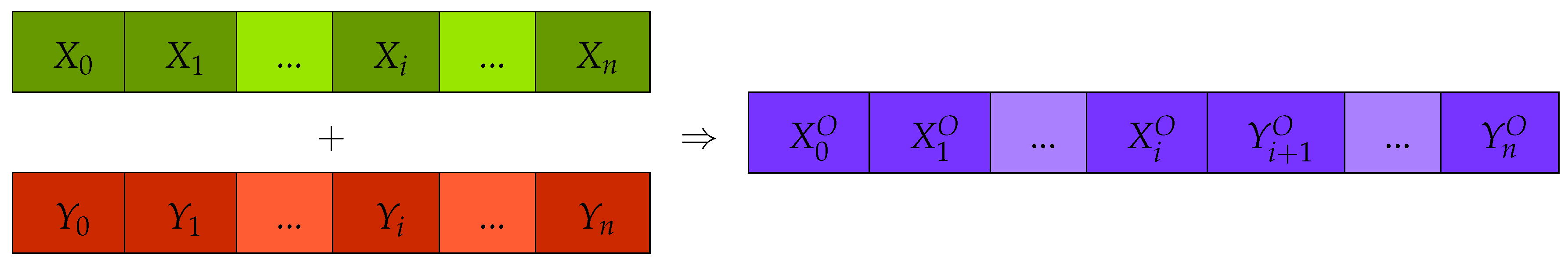
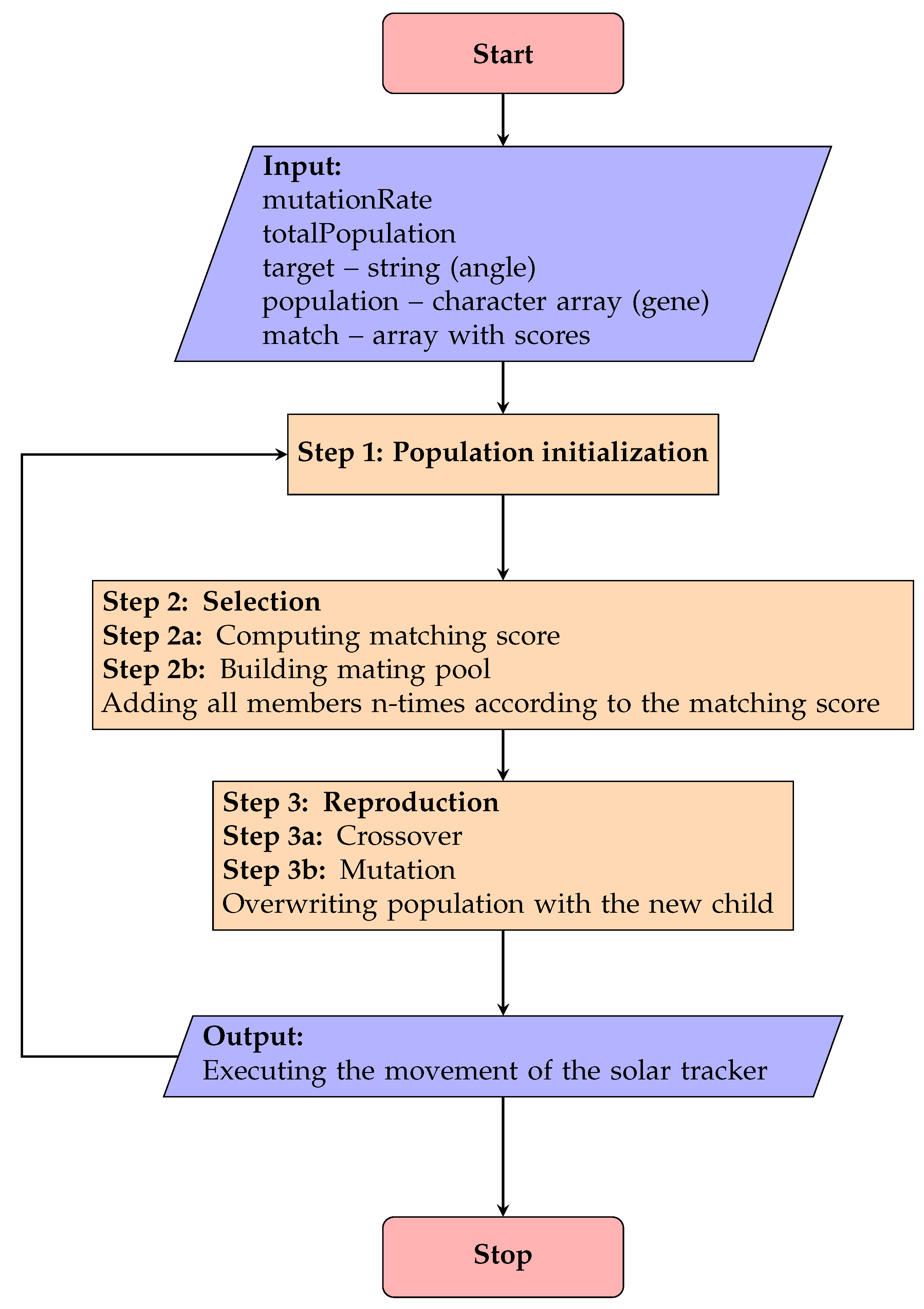
2.2. The Proposed Genetic Algorithm

In Figure 5, the simplified diagram of the genetic algorithm can be seen. A solar tracker robot that can learn to track the Sun can use this diagram.
Some terms of biological genetics are used in the genetic algorithm, and their translations into software may be slightly different from their original meanings.
The strings that are sent to each motor or joint to move the solar tracker robot are the deoxyribonucleic acids (DNAs ) or gene arrays, which are actually command strings or character arrays. Actually, a gene should look like “9;120”, which shows that the numbers represent the angle of movement of each motor at the joints of the solar tracker, with 9 at one joint and 120 at the other joint. Gene arrays are command strings constructed from a character array for the robot.
A gene is a number, such as “9”. Here, the phenotype is “9”, as the natural movement of the solar tracker robot, for example, requires one joint to move 9 . In the previous example, the genotype is represented by the value of the American Standard Code for Information Interchange (ASCII) for the character “9”, indicating that the genotype is 57. Each time a gene is created, random ASCII numbers are created, which are then converted into the appropriate character to produce the phenotype for the solar tracker robot or the motor command string.
All DNAs, gene arrays, or solar tracker robot command strings (character arrays) are the parents and will be placed in a mating pool to mate or crossover for the purpose of producing a child or offspring. The crossover is accomplished by concatenating one half of one parent (solar tracker robot command string) with the other half of the other parent (solar tracker robot command string). The offspring or child will be created through this procedure.
In genetics, the term “mutation” refers to the alteration of a random gene. This is also present in biological organisms, and without it, some organisms would be too similar to each other. Because of this, there are no two people who are identical; they share some characteristics with their parents, but they are slightly different from each other. Because of this, children with brown hair can sometimes be born to blond parents. Mutation is also used because sometimes a system cannot evolve if there is no change in the genes. This means that sometimes, when in the mating pool, the parents are very similar and only a mutation can bring the system out of a dead end or from a situation from where it cannot evolve. In programming, a mutation is the substitution of a random character for another at a random location in the gene array. This is accomplished by generating a random ASCII value which is then transformed into the corresponding character according to the ASCII table and inserted in the gene array at a random position.
The genetic algorithm requires the following variables: totalPopulation (e.g., 150, the number of parents (solar tracker robot command string) to mate with each other), target (solar tracker robot command string to point toward the Sun), population (generated solar tracker robot command character array (gene array)), and match (computed fitness score array).
The generation of command character arrays (genes) of the solar tracker robot is known as the population initialization step in this process.
Selection is the second stage. In this step, the fitness score (or the matching score) is calculated, indicating that the solar tracker robot command with the highest fitness score is the closest match. As a result, a breeding pool is created. The solar tracker robot command strings that will be crossed over in the mating pool to produce a new offspring (solar tracker robot command string) are here. Robot command strings with a higher fitness or matching score are added to the mating pool more frequently. To have a better chance of mating and producing offspring, the higher the fitness score, the more robot command strings are added to the mating pool.
Reproduction is the third step. Reproduction is the crossover itself. Two random robot command strings are taken from the mating pool and crossed over. Crossing over is accomplished by joining the first half of the first robot command string with the other half of the other robot command string. Mutation is a crucial component of the genetic algorithm and is also present in biological organisms in genetics. When two very similar robot command strings (the parents) cross, there is no way to find the target robot command string (the child), which is where the motors should be positioned to produce the robot’s most precise positioning. Mutating is the only way to obtain the target command string for the robot in this situation. Mutation refers to altering the robot command string with a random character and value. This indicates that there was a mutation in a gene (i.e., in a character from the robot’s command). This can be seen in biological organisms in genetics, as a child with blue eyes can be the offspring of a parent with green eyes and another parent with brown eyes. The new child will completely overwrite the following population. This indicates that the new child will be in the mating pool, become a parent, and be able to be crossed with another parent to produce his own offspring. The system will continue to cross until the target robot command string is obtained. The child will create a new child. The number of generations required to obtain the target robot command string varies, depending on the complexity of the command string. Each new child starts a new generation. A target robot command string is created for one motor and then for the other motor. After each generation, the robot’s command string is sent to the solar tracker, which then starts tracking the Sun. After each generation, the program turns back to create a new mating pool from the new generation.

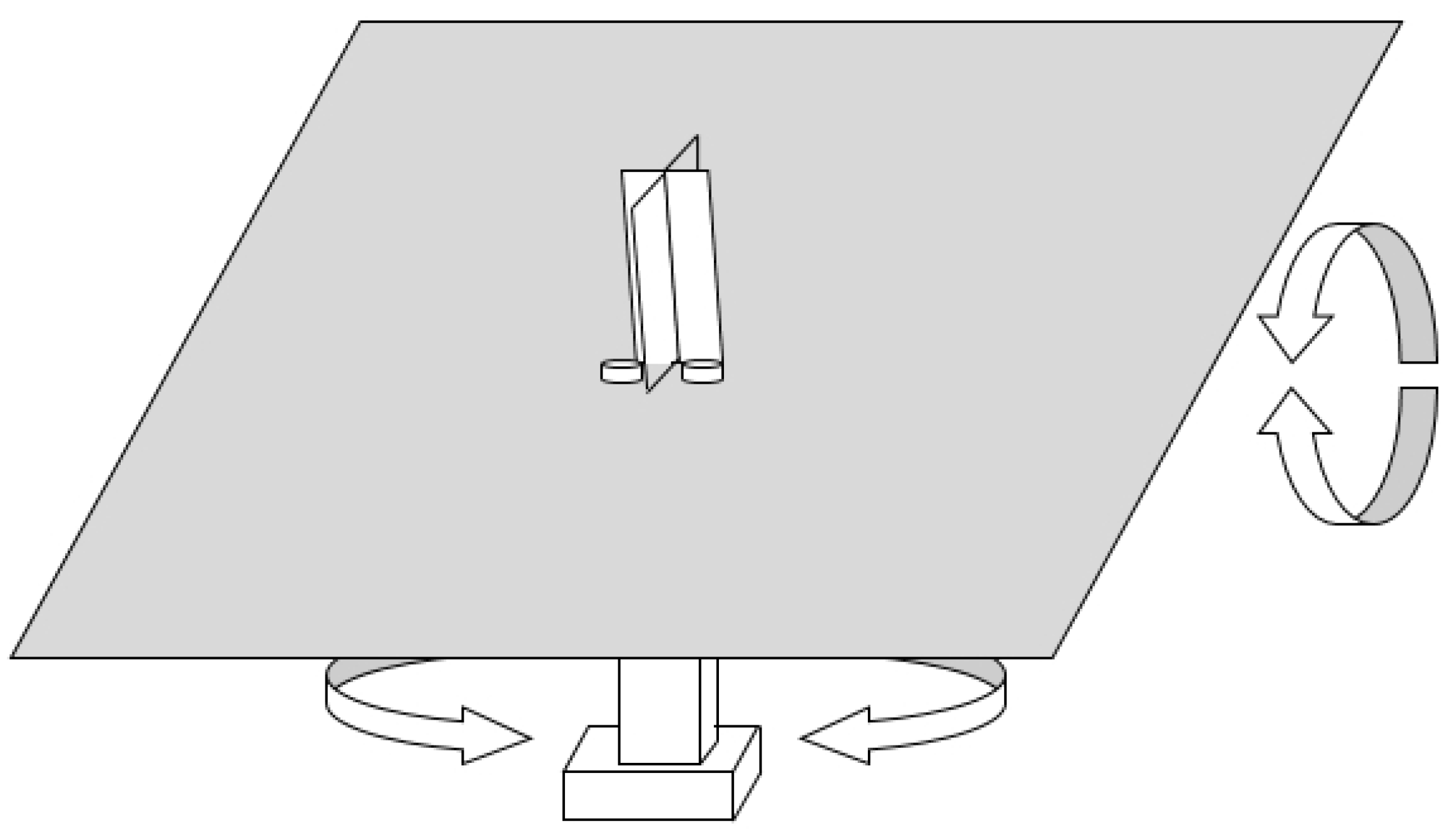
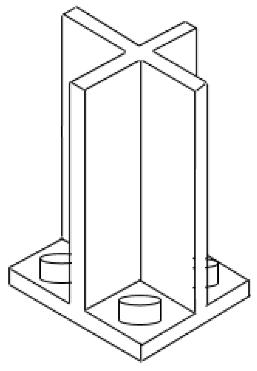
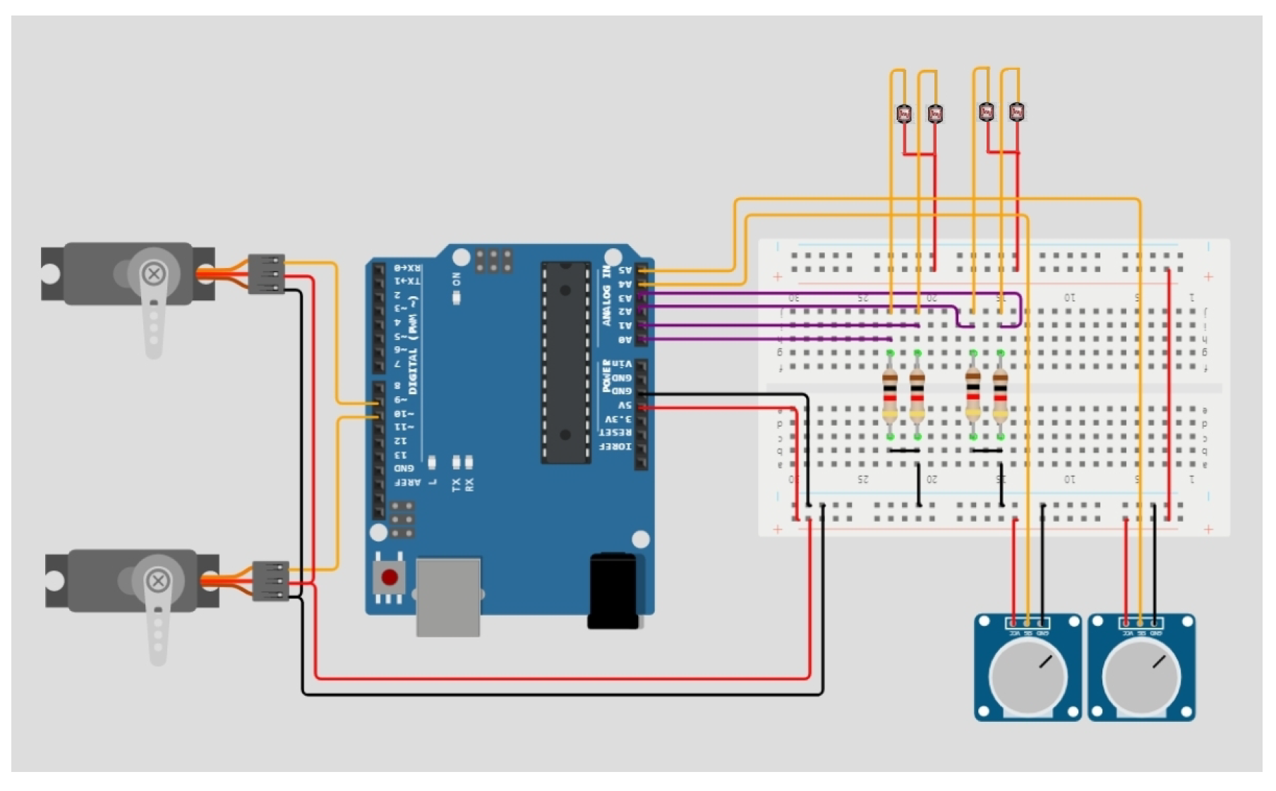
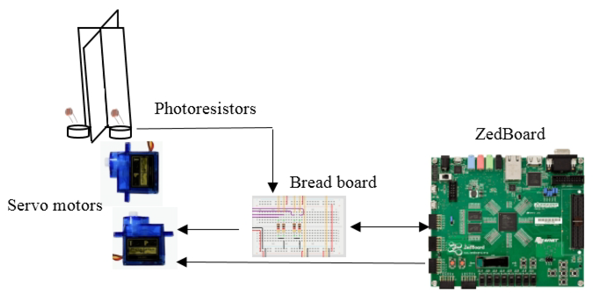
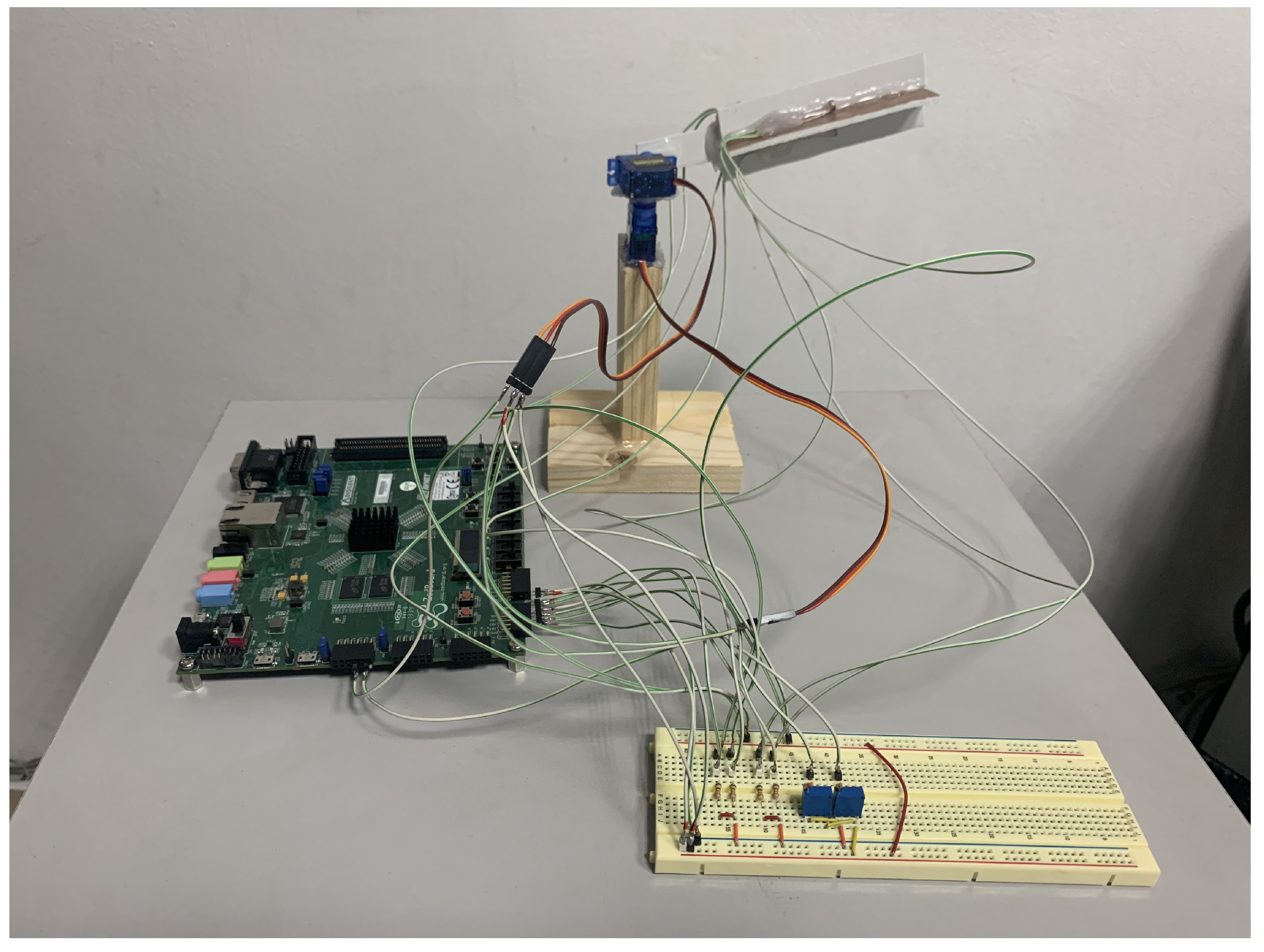
2.3. Hardware Implementation

In Figure 6, the circuitry used in addition to the microcontroller board is visible. The circuitry was made up of four photoresistors connected in series with four 1 k Ω resistors that were connected to the first four analog input ports of the microcontroller. Additionally, two 10 k Ω potentiometers were connected to the analog input ports A4 and A5 to set the rotation speed and movement angle tolerances.
The servomotors were connected to the digital ports D9 and D10.
In the manner depicted in Figure 2, the photoresistors were connected, and in this way, the robot moved in the same direction as the Sun, both horizontally and vertically. If a solar panel was also attached, the robot could rotate the solar panel in the Sun’s direction, increasing its efficiency by up to 30%.
The software on the microcontroller reads the photoresistors and controls the servomotors accordingly.
When wind sensors or anemometers are replaced with photoresistors, the algorithm can also be extended to wind turbines.
In Figure 7, the circuitry for the solar tracker robot can be seen, including the development board with an ATmega328 microcontroller and breadboard. This circuitry can also be used for simulation purposes. It is important to note that the potentiometers and photoresistors are located outside the breadboard.

3. Results

3.1. Experimental Results

The system had to be constructed using the block diagram in Figure 8. If we divided the outer word using the x 0 y Cartesian coordinate system, as can be seen, then there would be four photoresistors separated by walls to obtain light information from the four quadrants. According to the x 0 y Cartesian coordinate system, there are two servomotors that can facilitate movement. There is a breadboard with wires and electrical components (potentiometers for the motors and resistors for the photoresistors). The development board that oversees the entire system is the Digilent ZedBoard FPGA board. An ATmega328 microcontroller architecture that can be programmed in C language was chosen as the preferred approach. The microcontroller was built on the FPGA system, due to the fact that in the case of upgrading the system to a more performant microcontroller, this could be accomplished just by reprogramming the FPGA.
In Figure 9, the results of the solar tracker robot experiment can be seen. The method of gluing the servomotors together so that they could move horizontally and vertically can also be seen. Furthermore, it is clear how the separation walls of the photoresistors were constructed to receive light according to the four quadrants of the Cartesian system x 0 y . The ATmega328 microcontroller was developed on the Zynq-7000 SoC of the ZedBoard development board, which is used to control the entire system. The ZedBoard is easily recognizable in the image. A breadboard with external circuitry that makes the system work can also be seen. Photoresistors require resistors, and servomotors require potentiometers to set the solar tracker’s rotation speed and tolerances for horizontal and vertical movements.

3.2. Discussions

The advantage of the system is that with two servomotors and a correct algorithm, a solar tracker robot can be made which can follow the Sun, thus increasing the efficiency of the solar panel. When the efficiency of a solar panel is increased, the space occupied by solar panels can be reduced in a solar panel farm.
A possible disadvantage is that the genetic algorithm can sometimes take time before it will reach a mature generation that can function as needed. It is also a task to try different parameters of the genetic algorithm to find the best end result.
The idea of a solar tracker is not new. The novelty of this paper is to increase the precision of a solar tracker with genetic algorithms. Other researchers have found that efficiency can increase by up to 30% if a device is used that tilts the solar panels toward the Sun. It is clear that rotating solar panels toward the Sun can increase their efficiency. The aim of this paper is not to evaluate the efficiency of solar panel systems but to increase the precision of a solar tracker robot using evolutionary algorithms. If the maximum efficiency of a solar panel is just above 25%, then an increase of 30% with a solar tracker would surely compensate for the power consumption required for the servomotors and controller.
The genetic algorithm presented in this manuscript and the genetic algorithms of other researchers that have been published in the scientific literature are compared in Table 2.
As can be seen in Table 2, the proposed approach has the parameters of the genetic algorithm comparable to those of the known scientific literature. The total population was slightly higher, because a high population value could result in greater diversity when crossing. The generation number was quite low due to the fact that for the current approach, 50 was the maximum generation number when the system reached the desired maturity. This was obtained after many trials. Sometimes, the generation number was 30 or even lower. Compared to the results of other scientists, this is a very good result; the lower the generation number, the better the genetic algorithm. The crossover rate was also lower than that obtained by other researchers. The mutation rate was also very low. The last two parameters show that the genetic algorithm does not need too many crossings or mutations to obtain the desired result. The length of the string was not disclosed by the researchers, who did not generate a command string to control the robot. The length of the string is the length of the generated robot command string, and the length of this string differed for each robot. To reduce the number of generations, the best solution is to use short strings by having fewer bits, but if the command of the robot cannot be coded in fewer bits, then there is no other solution than to use the command string regardless it’s length (e.g., 10, 12, or even more bits).

4. Conclusions

The genetic algorithm on how a solar tracker robot can follow the Sun and evolve, was presented. With evolution, the solar tracker robot can be more precise in tracking the Sun. The software implementation of the calculation method was tested on a real robotic system.
Both the method and the fundamental concept of the algorithms used were presented. The original model was contrasted with studies in the specialized literature and the advantages and differences of the presented method were highlighted.
The formulas used in the solar tracker robot program were highlighted in this paper.
Further enhancements can be made by implementing the genetic algorithm on other platforms, such as FPGA boards with the Zynq-7000 SoC (e.g., the Zybo). A Raspberry Pi can also be used to implement the system. The actual system was implemented in the C programming language, but the system can be implemented in Python or Java. The best enhancement could be to port the system to a full-sized solar tracker robot.
The calculation method and the movement control algorithms are original:
  • The algorithm was used by the solar tracker robot to track the Sun with more precision.
  • The algorithm was put in an implementable form for the computer source code.
  • The idea of how to glue the two motors in order for the solar tracker to be able to make horizontal and vertical movements is original.
  • The genesis of all formulas was demonstrated and validated through controlled robotic movement.
  • The robot was built, the circuit was made, and the software was written by the authors.

Author Contributions

Conceptualization, R.S. and R.-S.R.; methodology, R.S. and R.-S.R.; software, R.S.; validation, R.S.; formal analysis, R.S. and R.-S.R.; investigation, R.S. and R.-S.R.; resources, R.S.; data curation, R.S.; writing—original draft preparation, R.S.; writing—review and editing, R.S.; visualization, R.S.; supervision, R.S.; project administration, R.S.; funding acquisition, R.S. All authors have read and agreed to the published version of the manuscript.

Funding

This research was founded by the Academy of Romanian Scientists (Splaiul Independentei 54, 050044) in Bucharest, Romania. This research was also founded by the Politehica University Timisoara.

Data Availability Statement

All the images are available on request from the corresponding author.

Acknowledgments

The authors would like to thank the Academy of Romanian Scientists (Splaiul Independentei 54, 050044) in Bucharest, Romania for the given support. The authors also thank the Politehnica University Timisoara for the given support.

Conflicts of Interest

The authors declare no conflict of interest.

Abbreviations

The following symbols and abbreviations are used in this manuscript:
CdTeCadmium tellurium
CIGSCopper indium gallium selenide
PDWPassive dynamic walking
DoFDegrees of freedom
3DThree-dimensional
ACAlternating current
DSPDigital signal processing
( 0 x , 0 y ) Coordinates
MEMSMicroelectromechanical systems
ASCIIAmerican Standard Code for Information Interchange
fFitness function
g i Gene (character)
t i Target gene (character)
C p Crossover parameter
G n Generation number
G T Total generation number
M I N , M A X Minimum, maximum
P m Random middle point
M p Mutation rate or parameter
NNumber of joints ( N = 2 )
KTotal kinetic energy
PPotential energy
θ i Joint variable for the i t h joint
θ i ˙ First time derivative for θ i
τ i Generalized force (torque) at the i t h joint
θ Generalized joint coordinates
M ( θ ) Mass matrix or kinetic energy matrix
C ( θ , θ ˙ ) Centrifugal and Coriolis forces
G ( θ ) Gravity force
Φ ( θ , θ ˙ , θ ¨ ) Generalized forces
m k k ( θ ) Inertia at joint k when joint k accelerates ( m k k > 0 )
m k j ( θ ) Inertia observed at joint k when joint j accelerates
c k i i ( θ ) Coefficient of the centrifugal force at joint k when joint i is moving ( c i i i = 0 , i )
c k i j ( θ ) Coriolis force at joint k when both joints i and j are moving
m 1 , m 2 Masses
MMass matrix, all the mass
θ ¨ Linear acceleration terms
θ ˙ Quadratic velocity terms
θ Nonlinear configuration terms
gGravity acceleration vector
r c i Location of the center of mass for link i
r c m Place of the center point of the mass
rPlace of reference
d m Differential component of the mass at point r
m i Mass of particle i
r i Distance to particle i
DNAsDeoxyribonucleic acids
x 0 y Cartesian coordinate system
FPGAField-programmable gate arrays
SoCSystem on a chip
GAGenetic algorithm

References

  1. Lim, T.; Kwak, P.; Song, K.; Kim, N.; Lee, J. Automated dual-axis planar solar tracker with controllable vertical displacement for concentrating solar microcell arrays. Prog. Photovoltaics 2017, 25, 123–131. [Google Scholar] [CrossRef]
  2. Fathabadi, H. Comparative study between two novel sensorless and sensor based dual-axis solar trackers. Sol. Energy 2016, 138, 67–76. [Google Scholar] [CrossRef]
  3. Rustu, E.; Ali, S. Performance comparison of a double-axis sun tracking versus fixed PV system. Sol. Energy 2012, 86, 2665–2672. [Google Scholar]
  4. Lee, C.Y.; Chou, P.C.; Chiang, C.M.; Lin, C.F. Sun Tracking Systems: A Review. Sensors 2009, 9, 3875–3890. [Google Scholar] [CrossRef] [PubMed]
  5. Mousazadeh, H.; Keyhani, A.; Javadi, A.; Mobli, H.; Abrinia, K.; Sharifi, A. A review of principle and sun-tracking methods for maximizing solar systems output. Renew. Sustain. Energy Rev. 2009, 13, 1800–1818. [Google Scholar] [CrossRef]
  6. De Macedo, M.M.; Saldias, C.E.P.; Ando Junior, O.H. Mathematical Modeling of a Solar Tracker System Two Axes for Generation Photovoltaics. IEEE Lat. Am. Trans. 2016, 14, 4054–4062. [Google Scholar] [CrossRef]
  7. Kaur, T.; Mahajan, S.; Verma, S.; Gambhir, J. Arduino based low cost active dual axis solar tracker. In Proceedings of the ICPEICES 2016—1st International Conference on Power Electronics, Intelligent Control and Energy Systems, Delhi, India, 4–6 July 2016; pp. 1–5. [Google Scholar]
  8. Saumya, G.; Ankit, M.; Paurush, B. Prototype of household inverter using dual-axis solar tracker to overcome shortage of energy. In Proceedings of the InCITe 2016—International Conference on Information Technology, Noida, India, 6–7 October 2016; pp. 160–165. [Google Scholar]
  9. Fathabadi, H. Novel high efficient offline sensorless dual-axis solar tracker for using in photovoltaic systems and solar concentrators. Renew. Energy 2016, 95, 485–494. [Google Scholar] [CrossRef]
  10. Adapa, B.; Mamidi, R.P.; Alapati, S. Spacing Optimization Study of Single-axis Polar Mounted Solar-thermal Passive Tracker based Solar Photovoltaic Plan. Int. J. Renew. Energy Res. 2016, 6, 1491–1495. [Google Scholar]
  11. Jovanovic, V.M.; Ayala, O.; Seek, M.; Marsillac, S. Single Axis Solar Tracker Actuator Location Analysis. In Proceedings of the SoutheastCon 2016, Norfolk, VA, USA, 30 March–3 April 2016. [Google Scholar]
  12. Agee, J.T.; Davidson, I.E.; Kombani, L.T. Intelligent Proportional Integral Control of a Polar Axis Solar Tracker. In Proceedings of the PSC 2016—Clemson-University Power Systems Conference, Clemson, SC, USA, 8–11 March 2016. [Google Scholar]
  13. Geijtenbeek, T.; van de Panne, M.; van der Stappen, A.F. Flexible Muscle-Based Locomotion for Bipedal Creatures. ACM Trans. Graph. 2013, 32, 1–11. [Google Scholar] [CrossRef]
  14. Renan, V.; Eduardo, A.; Teo, R. Trajectory Planning For Car-like Robots Through Curve Parametrization And Genetic Algorithm Optimization With Applications To Autonomous Parking. IEEE Lat. Am. Trans. 2022, 20, 309–316. [Google Scholar]
  15. Loredo-Flores, A.; Gonzalez-Galvan, E.J.; Cervantes-SÁnchez, J.J.; Martinez-Soto, A. Optimization of Industrial, Vision-Based, Intuitively Generated Robot Point-Allocating Tasks Using Genetic Algorithms. IEEE Trans. Syst. Man Cybern. Part C (Appl. Rev.) 2008, 38, 600–608. [Google Scholar] [CrossRef]
  16. Gary, P.; Richard, Z. Learning Area Coverage for a Self-Sufficient Hexapod Robot Using a Cyclic Genetic Algorithm. IEEE Syst. J. 2014, 8, 778–790. [Google Scholar]
  17. Estrada, F.A.C.; Lozada, J.C.H.; Gutiérrez, J.S.; Valencia, M.I.C. Performance between Algorithm and micro Genetic Algorithm to solve the robot locomotion. IEEE Lat. Am. Trans. 2019, 17, 1244–1251. [Google Scholar] [CrossRef]
  18. Jamwal, P.K.; Hussain, S.; Xie, S.Q. Three-Stage Design Analysis and Multicriteria Optimization of a Parallel Ankle Rehabilitation Robot Using Genetic Algorithm. IEEE Trans. Autom. Sci. Eng. 2015, 12, 1433–1446. [Google Scholar] [CrossRef]
  19. Tsai, C.C.; Huang, H.C.; Chan, C.K. Parallel Elite Genetic Algorithm and Its Application to Global Path Planning for Autonomous Robot Navigation. IEEE Trans. Ind. Electron. 2011, 58, 4813–4821. [Google Scholar] [CrossRef]
  20. Kamio, S.; Iba, H. Adaptation technique for integrating genetic programming and reinforcement learning for real robots. IEEE Trans. Evol. Comput. 2005, 9, 318–333. [Google Scholar] [CrossRef]
  21. Tewolde, G.S.; Sheng, W. Robot Path Integration in Manufacturing Processes: Genetic Algorithm Versus Ant Colony Optimization. IEEE Trans. Syst. Man Cybern.-Part A Syst. Humans 2008, 38, 278–287. [Google Scholar] [CrossRef]
  22. Hornby, G.S.; Takamura, S.; Yamamoto, T.; Fujita, M. Autonomous evolution of dynamic gaits with two quadruped robots. IEEE Trans. Robot. 2005, 21, 402–410. [Google Scholar] [CrossRef] [Green Version]
  23. Tsai, C.C.; Huang, H.C.; Lin, S.C. FPGA-Based Parallel DNA Algorithm for Optimal Configurations of an Omnidirectional Mobile Service Robot Performing Fire Extinguishment. IEEE Trans. Ind. Electron. 2011, 58, 1016–1026. [Google Scholar] [CrossRef]
  24. Walker, J.H.; Garrett, S.M.; Wilson, M.S. The balance between initial training and lifelong adaptation in evolving robot controllers. IEEE Trans. Syst. Man Cybern. Part B (Cybernetics) 2006, 36, 423–432. [Google Scholar] [CrossRef]
  25. Huang, H.C. SoPC-Based Parallel ACO Algorithm and its Application to Optimal Motion Controller Design for Intelligent Omnidirectional Mobile Robots. IEEE Trans. Ind. Informatics 2013, 9, 1828–1835. [Google Scholar] [CrossRef]
  26. Kamel, M.A.; Yu, X.; Zhang, Y. Real-Time Fault-Tolerant Formation Control of Multiple WMRs Based on Hybrid GA–PSO Algorithm. IEEE Trans. Autom. Sci. Eng. 2021, 18, 1263–1276. [Google Scholar] [CrossRef]
  27. Gao, G.; Mei, Y.; Xin, B.; Jia, Y.H.; Browne, W.N. Automated Coordination Strategy Design Using Genetic Programming for Dynamic Multipoint Dynamic Aggregation. IEEE Trans. Cybern. 2022, 52, 13521–13535. [Google Scholar] [CrossRef]
  28. Ju, Z.; Ji, X.; Li, J.; Liu, H. An Integrative Framework of Human Hand Gesture Segmentation for Human–Robot Interaction. IEEE Syst. J. 2017, 11, 1326–1336. [Google Scholar] [CrossRef] [Green Version]
  29. Datta, R.; Pradhan, S.; Bhattacharya, B. Analysis and Design Optimization of a Robotic Gripper Using Multiobjective Genetic Algorithm. IEEE Trans. Syst. Man Cybern. Syst. 2016, 46, 16–26. [Google Scholar] [CrossRef]
  30. Jamwal, P.K.; Hussain, S. Multicriteria Design Optimization of a Parallel Ankle Rehabilitation Robot: Fuzzy Dominated Sorting Evolutionary Algorithm Approach. IEEE Trans. Syst. Man Cybern. Syst. 2016, 46, 589–597. [Google Scholar] [CrossRef]
  31. Yamasaki, F.; Endo, K.; Kitano, H.; Asada, M. Acquisition of humanoid walking motion using genetic algorithm-Considering characteristics of servo modules. In Proceedings of the 2002 IEEE International Conference on Robotics and Automation (Cat. No.02CH37292), Washington, DC, USA, 11–15 May 2002; Volume 3, pp. 3123–3128. [Google Scholar]
  32. Kong, J.S.; Lee, B.H.; Kim, J.G. A study on the gait generation of a humanoid robot using genetic algorithm. In Proceedings of the SICE 2004 Annual Conference, Sapporo, Japan, 4–6 August 2004; Volume 1, pp. 187–191. [Google Scholar]
  33. Endo, K.; Maeno, T.; Kitano, H. Co-evolution of morphology and walking pattern of biped humanoid robot using evolutionary computation: Designing the real robot. In Proceedings of the 2003 IEEE International Conference on Robotics and Automation (Cat. No.03CH37422), Taipei, Taiwan, 14–19 September 2003; Volume 1, pp. 1362–1367. [Google Scholar]
  34. Choi, S.H.; Choi, Y.H.; Kim, J.G. Optimal walking trajectory generation for a biped robot using genetic algorithm. In Proceedings of the 1999 IEEE/RSJ International Conference on Intelligent Robots and Systems. Human and Environment Friendly Robots with High Intelligence and Emotional Quotients (Cat. No.99CH36289), Kyongju, Republic of Korea, 17–21 October 1999; Volume 3, pp. 1456–1461. [Google Scholar]
Figure 1. A simplified drawing of the proposed device.
Machines 11 00430 g001
Figure 2. Dividing the sensors with walls for the Sun-tracking robot.
Machines 11 00430 g002
Figure 3. Crossover.
Machines 11 00430 g003
Figure 4. Mutation.
Figure 4. Mutation.
Machines 11 00430 g004
Figure 5. Simplified diagram of the genetic algorithm by which a solar tracker can track the Sun.
Machines 11 00430 g005
Figure 6. Schematics of the solar tracker robot.
Machines 11 00430 g006
Figure 7. Circuitry for the solar tracker robot using an ATmega328 microcontroller development board.
Machines 11 00430 g007
Figure 8. Block diagram of the solar tracker robot.
Machines 11 00430 g008
Figure 9. The solar tracker robot controlled by the Digilent ZedBoard FPGA board.
Machines 11 00430 g009
Table 1. Parameters of the genetic algorithm.
Total population150Generation number50
Crossover rate0.75Mutation rate0.01
String length8bits
Fitness function f = s n , g i = t i , i { 0 , n }
Table 2. Comparison of the parameters of the genetic algorithm of the proposed approach with other similar methods.
GA ParameterProposed ApproachF. Yamasaki et al. [31]Jung-Shik Kong et al. [32]K. Endo et al. [33]Sang-Ho Choi et al. [34]
Total population1505010020060
Generation number505030030050
Crossover rate0.750.90.080.80.92
Mutation rate0.010.020.050.050.03
String length (bits)8---10
Disclaimer/Publisher’s Note: The statements, opinions and data contained in all publications are solely those of the individual author(s) and contributor(s) and not of MDPI and/or the editor(s). MDPI and/or the editor(s) disclaim responsibility for any injury to people or property resulting from any ideas, methods, instructions or products referred to in the content.

