Article

Conical Grinding Wheel Ultrasonic-Assisted Grinding Micro-Texture Surface Formation Mechanism

1
Maritime College, Tianjin University of Technology, Tianjin 300384, China
2
Tianjin Key Laboratory for Advanced Mechatronic System Design and Intelligent Control, School of Mechanical Engineering, Tianjin University of Technology, Tianjin 300384, China
3
National Demonstration Center for Experimental Mechanical and Electrical Engineering Education, Tianjin University of Technology, Tianjin 300384, China
4
School of Mechanical Engineering, Tianjin University, Tianjin 300350, China
*
Author to whom correspondence should be addressed.
Machines 2023, 11(4), 428; https://doi.org/10.3390/machines11040428
Submission received: 16 February 2023 / Revised: 17 March 2023 / Accepted: 24 March 2023 / Published: 27 March 2023
(This article belongs to the Topic Advanced Manufacturing and Surface Technology)

Abstract

:
The rotating ultrasonic-assisted grinding (RUAG) experiment of the conical grinding wheel generated the intermittent pit-shaped micro-texture on the surface of the workpiece, reducing thermal damage and improving the lubrication characteristics compared with conventional grinding (CG). To further optimize the surface properties, this paper studied the formation mechanism of micro-texture. This study used as basis the theory that micro-debris volume equals the macroscopic material removal one to establish the mathematical equation of grinding depth. Thereafter, formulas of micro-texture feature parameters, including pit length, pit depth, and texture spacing were deduced. The solved microscopic grinding depth was alternatingly positive and negative, indicating that the alternating separation between the grinding grain and workpiece caused intermittent pits in the grinding. Through response surface analysis (RSA), this paper analyzed the relationships among macroscopic grinding depth, micro-texture feature parameters, and machining parameters (i.e., amplitude, feed rate, and rotational speed). Single-factor experiments of machining parameters, with finite element simulation and experiment methods, were performed to verify the theoretical micro-texture features. The simulated program formed three-dimensional surfaces with micro-textures. Their measurement results were consistent with the theoretical ones. Experimental results proved that the range of pit length covers the theoretical ones, further verifying the accuracy of the grinding depth model. For this grinding wheel, the 8–10 μm amplitude was optimal for better roughness, lubrication, and thermal damage. Roughness was improved when increasing the rotational speed or reducing the feed rate based on the experiment. If the rotational speed and feed rate exceed the limiting values, then continuous grinding will break down the abrasive grains and even damage the cubic boron nitride (CBN) coating. Experimental results likewise showed that the pit shape was closely related to the surface properties, which deserves further investigation.

1. Introduction

The conical grinding wheel is adopted to grind spiral bevel and worm gears, among others, which are applied to the movement of intersecting axes, particularly in cases of high transmission efficiency, stable transmission, and low noise. Gear manufacturing technology is undergoing focus transformation from high dimensional precision [1,2] to improved surface properties, mainly including thermal damage, lubrication, and roughness. Therefore, the ultrasonic-assisted grinding (UAG) method was applied in the gear manufacture.
Ultrasonic assisted technology has been widely recognized for its influence on morphology. In 1998, Uhlmann et al. analyzed the kinematic model of slow feed grinding with ultrasonic vibration on the surface, proving that RUAGcan significantly improve material removal rate and will not cause surface damage [3]. From 1998 to 2013, most researchers made ultrasonic assisted devices to verify the advantages of RUAG metals through experimental measurements and analyses, which mainly include improving roughness, decreasing grinding forces, reducing thermal cracks of surfaces, and high material rates. Zhao et al. completed an experimental research on surface characteristics in ultrasonic ductile-regime honing ZrO2 engineering ceramics with a new type of ultrasonic honing machine [4,5]. Tawakoli adopted ultrasonic assisted technology in dry grinding [6]. The results obtained showed that grinding forces decreased significantly. Mohsen Ghahramani Nik et al. proved the effect of ultrasonic vibration on the grinding of Ti6Al4V alloy [7]. W. M. Zeng et al. studied RUAG of advanced ceramics and discussed tool wear and cutting forces [8]. The Wu team [9,10,11] investigated elliptical ultrasonic-assisted grinding (EUAG) technologies. Most of the experiment results showed the feasibility of UAG in improving surface properties. Since 2014, the field of hard and brittle materials has found the application of UAG technologies [12,13] and carbon fiber-reinforced plastic [14], among others, other than special alloys. Research methods were transferred from qualitative to quantitative analyses. Past research has established mathematical models of cutting force [15,16], material removal rate [17,18], roughness [19], morphology [20], and cavitation bubble [21]; and further discussed the relationship between grinding parameters and ground surface.
Surface morphology is a critical influencing factor for surface performance. Recently, it has attracted considerable attention in the UAG field. Past research has investigated three types of ultrasonic vibration: longitudinal, tangential, and radial ultrasonic vibrations.
Early research has mainly focused on longitudinal UAG, in which ultrasonic vibration transfers to the tool head along the rotation axis. Wdowik et al. presented the results of measurements of surface micro-structure parameters after UAG and CG of ZrO2-based ceramic material [22]. Guo et al. investigated the influences of ultrasonic vibration parameters and tilt angle on the ground quality of micro-structured surfaces [23]. Zheng et al. built surface micro-texture models based on multi-grains motion equations [24]. Wen et al. proposed an improved model of a rough surface profile to find the microscopic feature parameters, such as the curvature radius of the grain, which are suitable for contact analysis and calculation [25,26]. One-dimensional longitudinal vibration often adopts a slender horn with a small tool head. Longitudinal ultrasonic vibration produces sinusoidal micro-texture, which changes the linear micro-texture of CG. Interference action of multiple abrasive grains subdivides the surface further. Compared with CG, micro-texture reduces surface roughness and thermal damage and improves lubrication characteristics.
Tangential ultrasonic assistant vibration has the same direction as the tangential one of the grinding wheel. In general, ultrasonic vibration is along the workpiece axis. Its advantage is that the circumnutation of abrasive particles forms a separation between abrasive particles and workpiece surface, which helps to decrease the grinding temperature, further reducing thermal damage. Jiang et al. established the surface micro-structure formation mechanism model by considering the continuous cutting process of grains [27]. Wang et al. developed the surface model and realized the optimized microstructure and high-precision surface ground through theory calculation [28]. Zhao et al. proposed a novel processing of ultrasonic vibration-assisted forming grinding gear [29]. For this vibration, ultrasonic vibration can only be applied in a specified workpiece, the dimensions of which are limited by the ultrasonic generator’s frequency.
Radial ultrasonic vibration is often combined with one of the other two vibrations to function. One case is the longitudinal radial ultrasonic vibration in the large disc grinding wheel. Radial amplitude is over 10% of the longitudinal one. The actual disc grinding wheel changes the longitudinal vibration of the transducer into a combination of longitudinal and radial. Compared with one-dimensional longitudinal ultrasonic, this case can form deeper micro-pits and also discontinuously separate abrasive particles and workpiece, thereby reducing thermal damage on the surface. Zhou et al. developed a comprehensive analytical model of MPD and micro-topography [30]. In this case, radial amplitude is determined by the dimension of the grinding wheel related to frequency; therefore, it is difficult to adjust. The other tangential radial ultrasonic vibration case was realized by elliptical vibration. Wang et al. [31] analyzed the topography-generation mechanism of a workpiece surface evolved using EUAG, with axial and radial ultrasonic vibration applied on the workpiece. Accordingly, they found the discontinuous motion by the radial ultrasonic vibration. Current theoretical research has focused on the trajectory interference mechanism of multiple abrasive grains, disregarding the influence of grinding depth and removal volume of abrasive grains.
The conical tool head studied in this paper decomposes the one-dimensional longitudinal vibration into two vibrations along the conical surface and vertical conical surface, which is equivalent to the longitudinal radial vibration. The longitudinal ultrasonic vibration and rotation motion of the grinding wheel can produce a sine wave trajectory. Moreover, radial ultrasonic vibration discontinuously hammers the workpiece surface, resulting in an intermittent grinding process and micro-pit textures. Compared with other radial vibrations, radial amplitude is more convenient to realize by the conical angle.

2. RUAG Kinematic Model

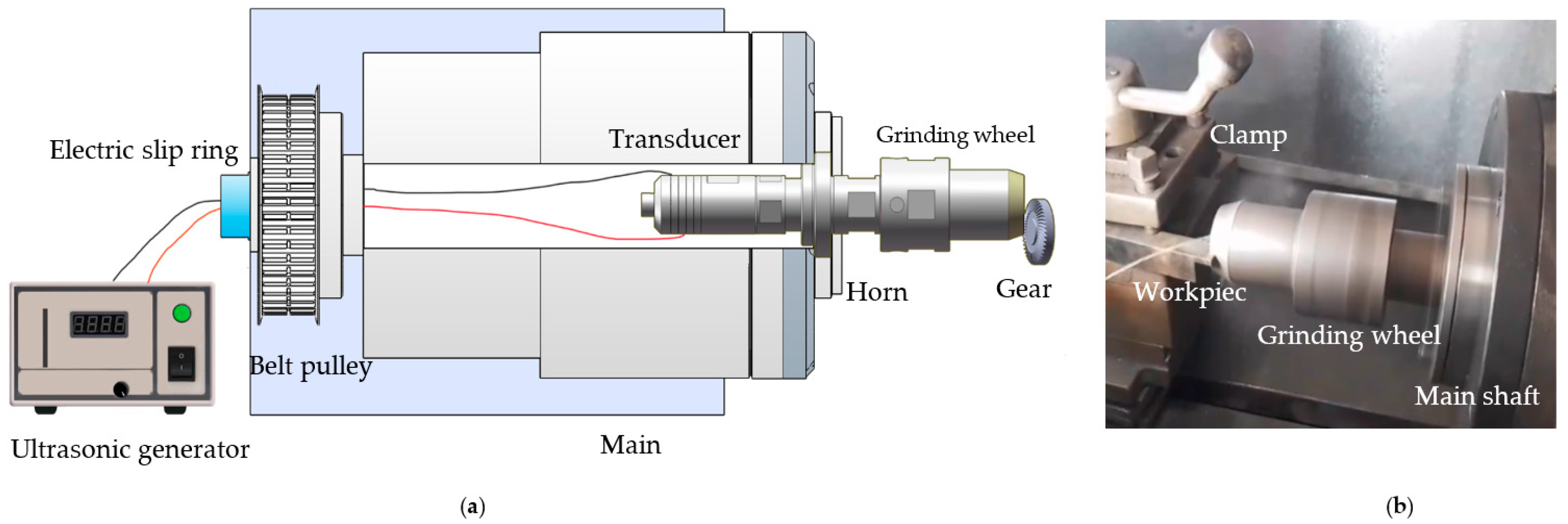
2.1. Experimental Setup

The RUAG device includes a CBN grinding wheel, amplitude horn, transducer, and electric slip ring, as shown in Figure 1. The machine tool spindle is bored to insert the device. The device is fixed and positioned by the cover and positioning journal, respectively. In the grinding process, the transducer generates the axial vibration and transmits it to the horn and grinding wheel. The grinding wheel simultaneously vibrates and rotates with the spindle, thereby forming the RUAG movement.

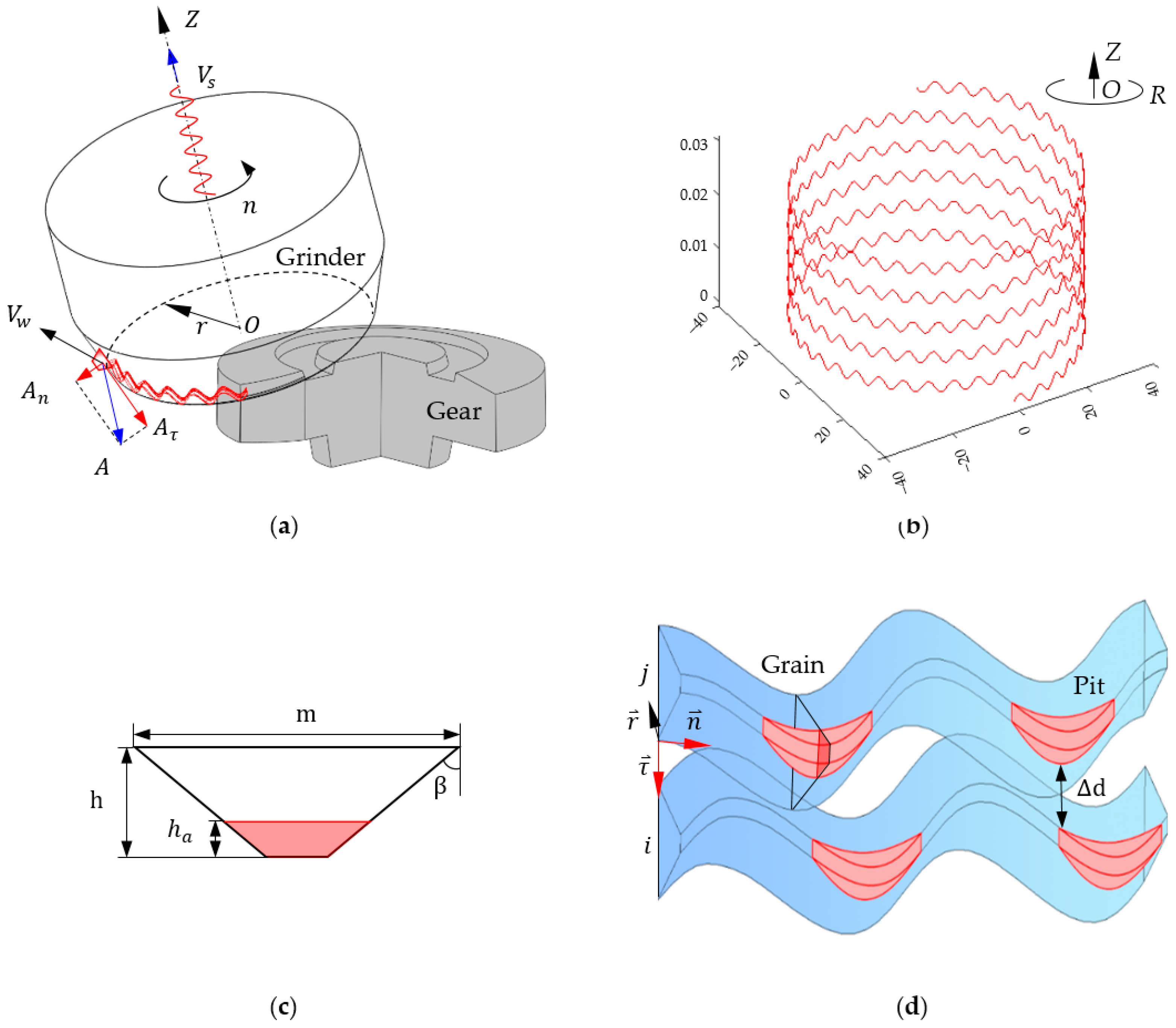
2.2. Theoretical Kinematic Model

Figure 2a shows the cylindrical coordinate system O ( R , Z ) , where O is the central point of the grinding wheel top surface. The grinding wheel’s dimensions are presented in Table 1. An abrasive grain is regarded as the frustum, located at a distance u from the top surface along the outside edge. Its motion comprises three components: (1) rotational speed n around the Z -axis with initial rotational angle φ 0 ; (2) ultrasonic vibration along the Z -axis with amplitude A , frequency f, and initial ultrasonic phase angle θ 0 ; and (3) feed speed V s along the Z -axis. The subsequent theoretical and simulated calculations are based on the assumption that grains have the same shape and evenly distributed on the ground surface.
Axial amplitude of RUAG is composed of two components. Normal amplitude, which is perpendicular to the grinding edge, hammers on the workpiece surface once a cycle. Tangential amplitude, which is parallel to the grinding edge, is combined with rotational motion to form a wave path. The motion trajectory of the abrasive grain is presented as Equation (1), as shown in Figure 2a:
R u = r + u sin α φ = 2 π n 60 t + φ 0 Z t = V s t + A sin ( θ 0 + 2 π f t )
where α e is the outside pressure angle and can be changed into the negative inside pressure angle α i . Velocity of the abrasive grain is deduced as Equation (2):
V w t = 2 π n 60 r u V z t = V s + 2 π f A cos ( θ 0 + 2 π f t )

3. Micro-Texture Feature Models

3.1. Pit Model

The grinding path length of an abrasive grain l p in an ultrasonic vibration cycle is as follows:
l p = 0 1 / f V w 2 + V z 2
when A = 0, and the curve length of the grinding path for CG is as follows:
l c = 0 1 / f 4 π 2 n 2 3600 ( r + u sin α e ) 2 + V s 2 .
According to the traditional definition, macroscopic grinding depth h p is the interference height between the grinding wheel and workpiece, often a positive constant. In RUAG, depth h p is considered a distance between the grinding wheel and workpiece. Therefore, the microscopic grinding depth of grain h a between the grain and workpiece changes with time or phase angle in the grinding, as shown in Figure 2c,d.
h a = h p + A n s i n ( 2 π f t + θ 0 )
The condition of intermittent grinding is h p < A n , in which depth h a is alternating positive and negative. In one ultrasonic cycle, when height h a is positive, grinding time t is in the range of [ 1 2 πf ( sin 1 ( h p A n ) + θ 0 ) , 1 2 f + 1 2 πf ( sin 1 ( h p A n ) + θ 0 ) ] s. Therefore, the pit length is as follows:
l s = 2 1 2 πf ( sin 1 ( h p A n ) + θ 0 ) 1 4 f V w 2 + V z 2
The three-dimensional model of the pit is the interference geometry between the sweeping body of abrasive grain moving along the trajectory and workpiece body, as shown in Figure 2d. Microscopic grinding depth h a is a variable. Therefore, the cross-sectional area of the interference part is described as follows:
S p = m 2 h t a n β + h a tan β h a .
Micro-debris volume V of abrasive grain in one cycle of RUAG is as follows:
V = 2 1 2 πf sin 1 ( h p A n ) 1 4 f S p V w 2 + V z 2 d t

3.2. Grinding Depth Equation

3.2.1. Effective Abrasive Gains Number

Abrasive grains are assumed to be distributed uniformly on the surface of the grinding wheel. The distance L between adjacent abrasive grains is as follows:
L = d g π 4 V g 1 ,
where V g is the volume of abrasive grain and d g is the average diameter of abrasive grains. The proportion of abrasive grains P involved in grinding is as follows:
P = 1 2 π p + e x 2 2 ,
where p is the lower limit of integration and its expression is as follows:
P = d m a x d m i n 2 a p × 4.4 δ / 2 ,
where d m a x and d m i n are the maximum and minimum diameters, respectively, of abrasive grain.
In time t of the grinding wheel, the grinding wheel rotational angle φ is as follows:
φ = 2 π n 60 · t .
The corresponding circumferential length of grinding wheel S ( u ) is as follows:
S u = φ · ( r + u sin α e ) .
Thereafter, dynamic effective abrasive gains number N of the grinding wheel is as follows:
N = P u 1 u 2 S ( u ) / d g + l 2 d u ,
where l is the average distance between two adjacent grains.

3.2.2. Calculation of Grinding Depth

In RUAG, one part of the grinding wheel participates in the grinding, relative to the workpiece dimensions. Therefore, grinding time is less than the rotational time of the grinding wheel. If the rotational angle of grinding is φ b , then the circumferential length of grinding wheel S b u is as follows:
S b u = φ b ( r + u sin α e ) ,
and the effective vibration period number of abrasive grain n t is as follows:
n t = φ b 2 π n 60 · f
The micro-debris volume of dynamic effective abrasive grains is as follows:
V r = V N n t .
Macroscopically, the total grinding depth of the grinding wheel is as follows:
a p = V s t sin α .
The macroscopic volume of material removal is as follows:
V R = a p u 1 u 2 S b u d u .
The macroscopic material removal volume equals the microscopic grinding debris:
V R = V r ,
in which macroscopic grinding depth h p of the abrasive grain is solved.
Furthermore, depth of the micro-texture is as follows:
A p = A n + h p .

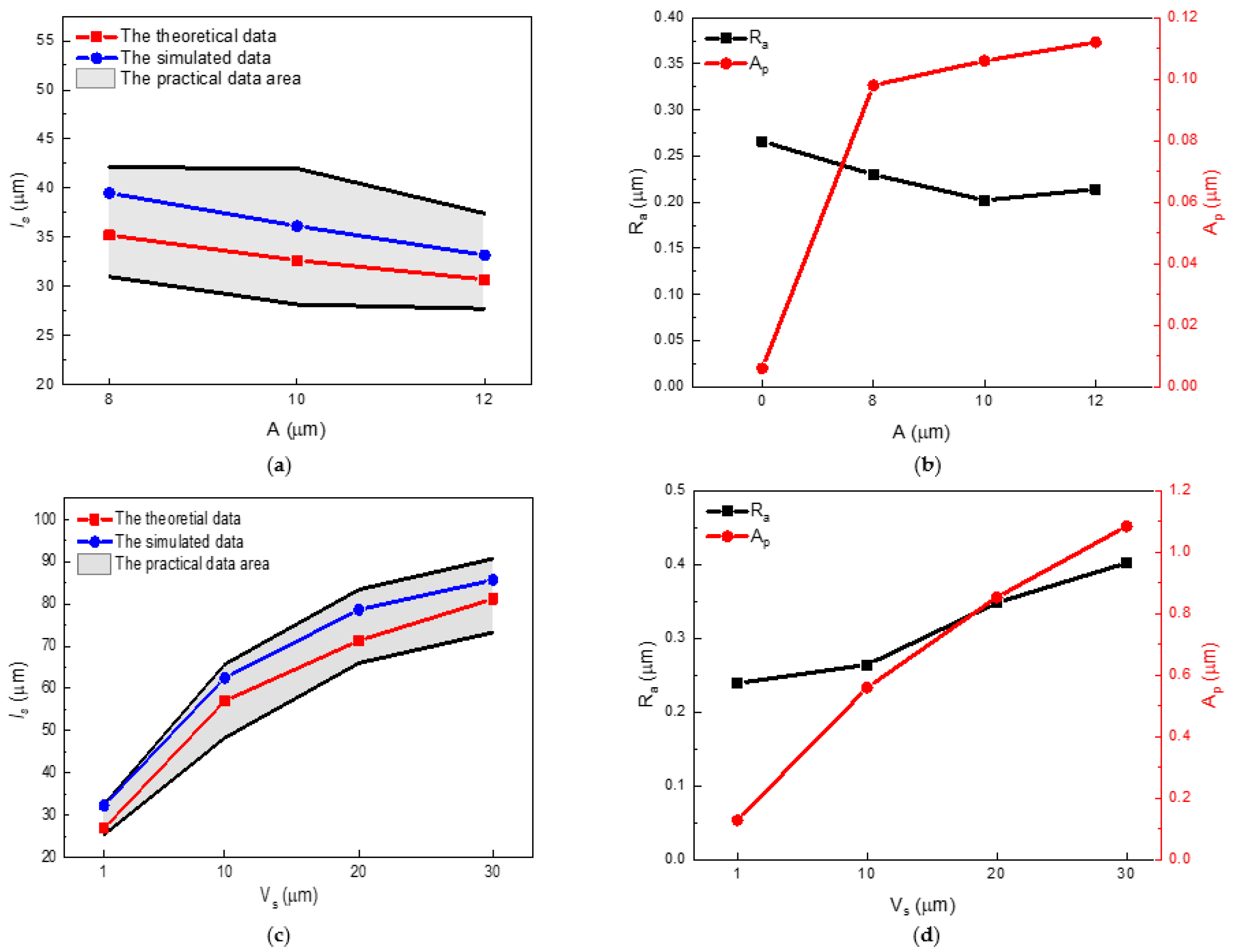
3.3. Calculation of Texture Spacing

As shown in Figure 2d, two grinding paths generated by the adjacent abrasive grains i and j have the phase angles θ i and θ j , respectively:.
d i = l + h h p A n sin θ i tan β + A τ sin θ i ,
d j = h h p A n sin θ j tan β + A τ sin θ j .
Texture spacing between them is as follows:
d = d i d j .
In intermittent grinding, if θ i = sin 1 ( h p A n ) and θ j = π 2 , then texture spacing d has the minimum value d m i n . When d m i n 0 , an interference exists, but no interference occurs when d m i n > 0 .
In continuous or conventional grinding, if θ i = θ j = π 2 , then d is minimum. When A = 0 in traditional grinding, d is constant as follows:
d = l + h h p tan β .

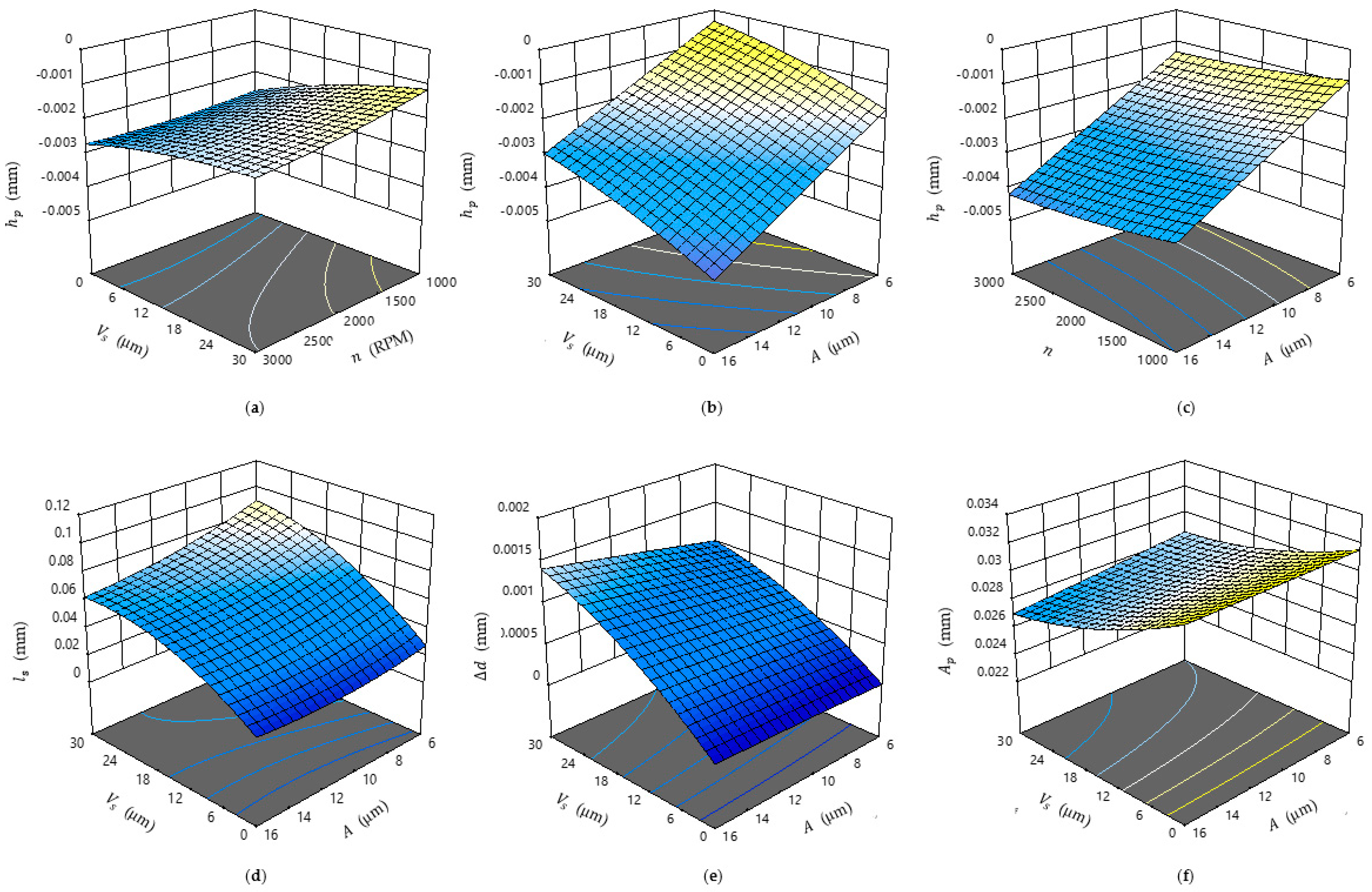
3.4. RSA of the Theoretical Model

Intermittent ultrasonic grinding facilitates the reduction of surface grinding temperature and avoidance of thermal damage. To achieve the proper parameters of intermittent grinding, RSA was used to analyze the influence of the machining parameters (i.e., feed speed, rotational speed, and amplitude) on grinding depth and micro-texture feature.

3.4.1. Experimental Design and Result

According to spiral bevel gear grinding conditions, the grinding wheel electroplates CBN of 400# grain dimension and 100% concentration. The workpiece material is 45# steel. Ultrasonic vibration frequency is about 19.82 KHz. The Box–Behnken module is used to carry out orthogonal experiments with the influencing factors: feed speed is 0–30 μm/s, rotational speed is 2000–3000 rpm, and amplitude is 6–12 μm. Response values include h p , l s , d , and A p . The RSA results are shown in Figure 3.

3.4.2. Discussion of RSA

Macroscopic grinding depth h p ranges from −0.348 μm to −4.800 μm. That is, intermittent grinding condition is satisfied in this range. Grinding height h p is positively correlated with feed speed V s and negatively correlated with other factors. Amplitude A has the most significant influence among the factors.
Texture spacing d is 0.023–0.032 mm, as shown in Figure 3d, indicating that no interference appears in the adjacent paths. Texture spacing d has a positive correlation to rotational speed n and a negative correlation with the others. The influence of feed speed is most remarkable.
Pit length l s and depth A p in Figure 3e,f are 0.018–0.120 mm and 0.004–1.95 μm, respectively. Length l s has negative and positive relations to amplitude and the others, respectively. Pit depth A p is negatively and positively correlated with rotational speed and the others, respectively. Influence of feed speed is most significant for both.

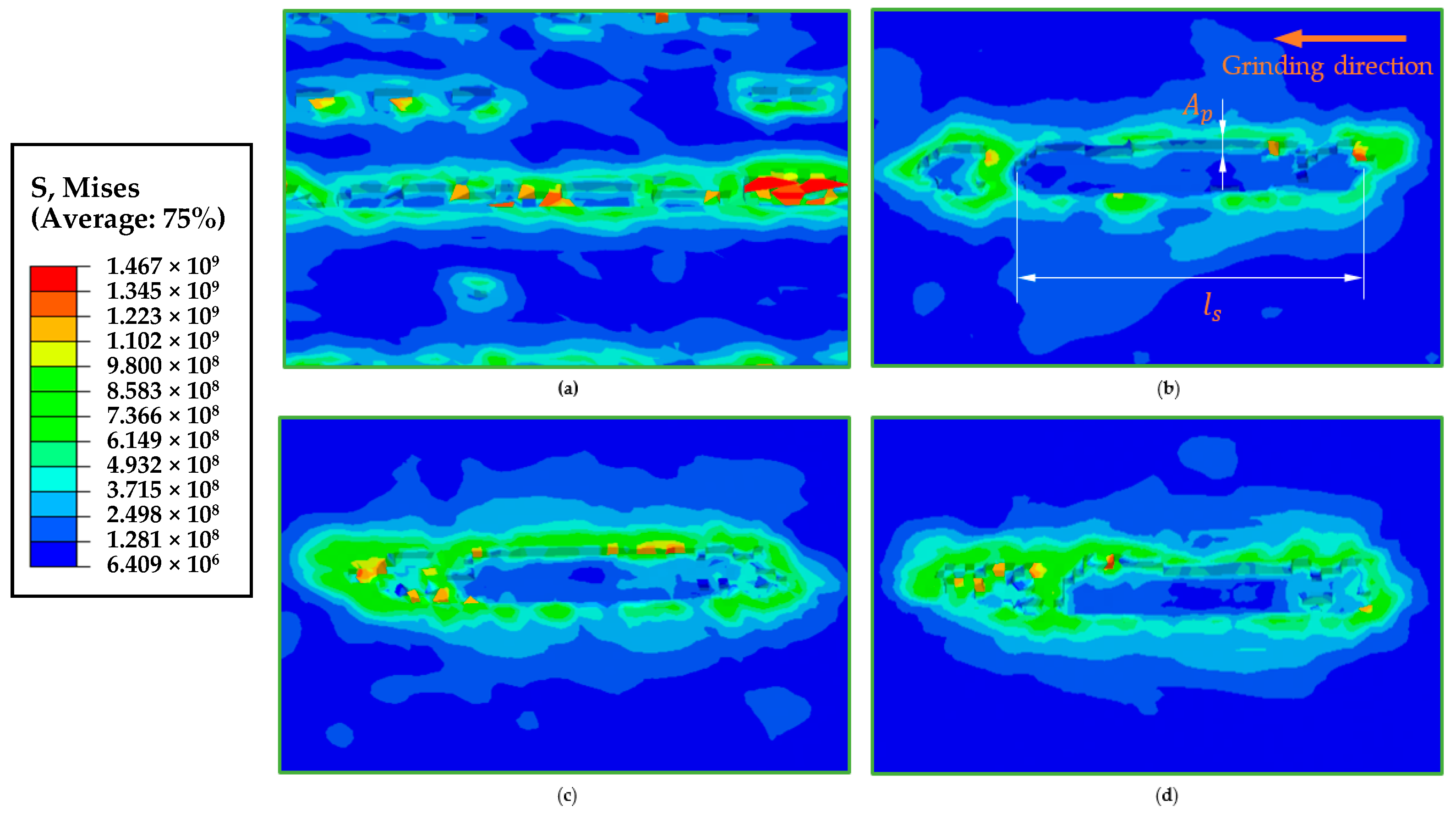
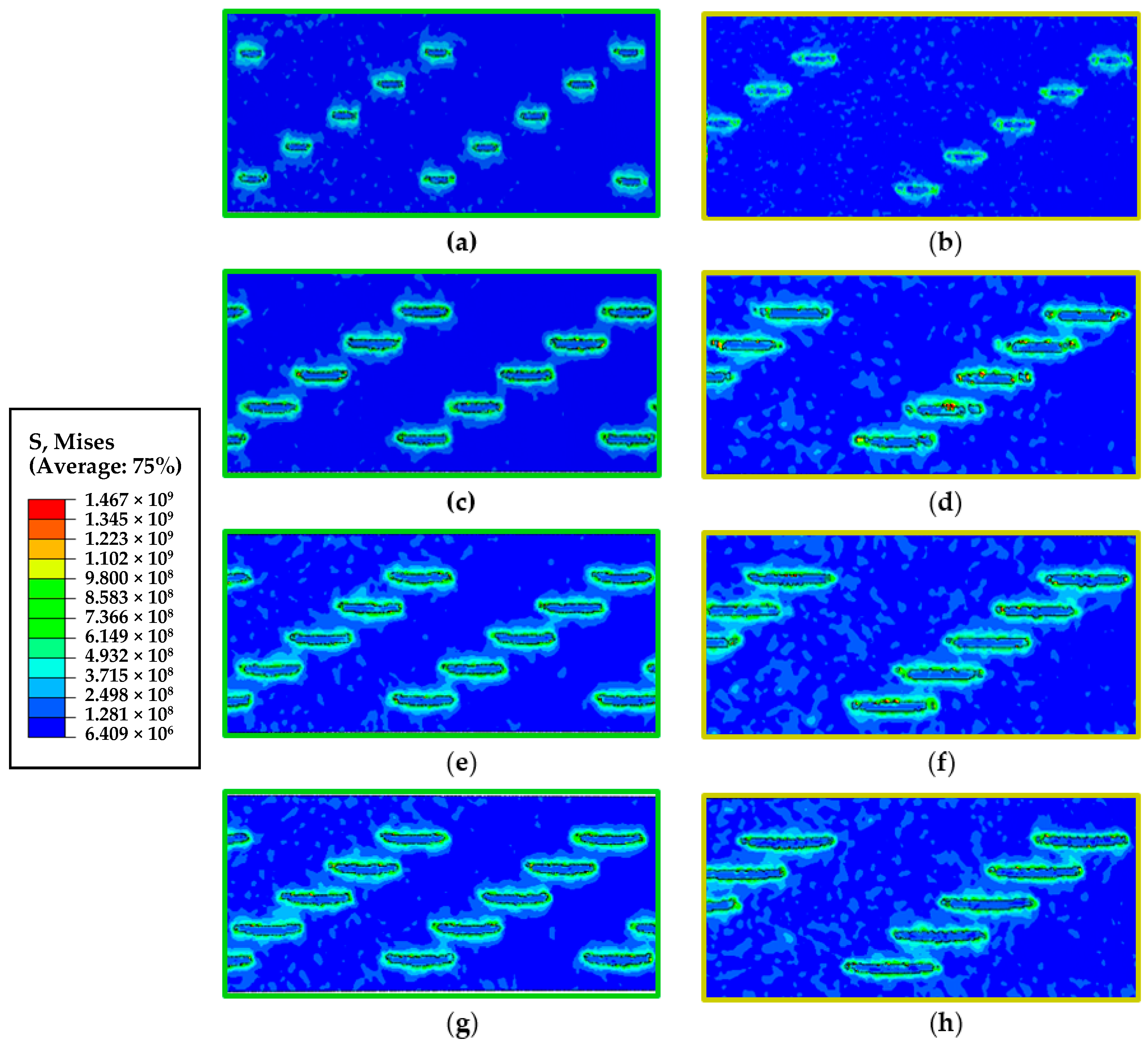
4. RUAG Progress Simulation

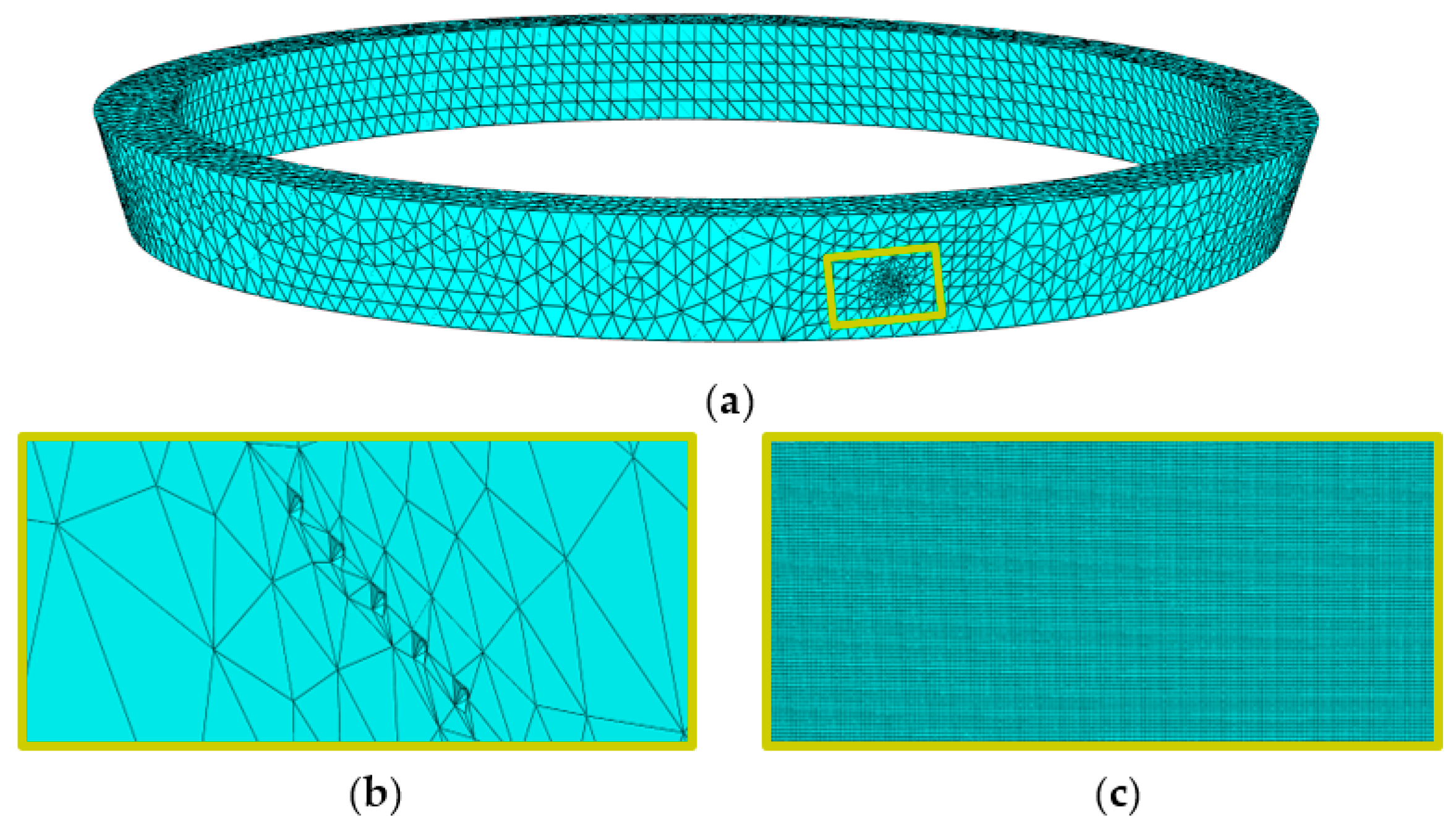
4.1. Finite Element Simulation Preprocessing

Figure 4 shows the finite element models of the grinding wheel and workpiece. Grains on the outside surface of the grinding wheel grind the concave of the workpiece. In Abaqus2020 software, grinding wheel’s meshes are tetrahedral, unit type is C3D4, and mesh size is 0.5 mm. The workpiece’s meshes are hexahedral, unit type is C3D8R, and mesh size is 0.001 mm.
The simulation program selected the Johnson–Cook plastic constitutive model for the workpiece to calculate the constitutive relationship. The Johnson–Cook shear failure criterion was applied to describe the separation of grinding debris and the workpiece. The relative parameters are presented in Table 2.
The program adopted the hard contact and penalty functions to carry out the normal and tangential contact calculations between abrasive grain and workpiece, respectively, with the latter having a friction factor of 0.3. Rigid and coupling constraints were set between the grinding wheel and the coordinate system. The workpiece was set as fixed, while rotational speed and axial ultrasonic motion were imposed on the grinding wheel. Simulation time is 0.003 s.

4.2. Micro-Texture Characteristic Analysis

The single-factor experiments of machining parameters comprise three groups, as shown in Table 3. In the grinding simulation, macroscopic grinding depth h p was set according to the theoretical calculation. The results are listed in Table 4, Table 5 and Table 6, where the depths of the micro-pit are all 1 μ m because the depths are less than the mesh size.
Figure 5 shows the micro-texture of group 1. With the amplitude increasing, pit length decreases, depth increases, and texture spacing does not decrease significantly. Figure 6 shows the comparison of the micro-texture of groups 2 and 3. Figure 6a,c,e,g show the micro-texture of group 2. Note that with feed speed increasing, pit length and depth increase and texture spacing decreases. Compared with group 2, Figure 6b,d,f,h show that group 3 has an increased pit length and decreased depth. Texture spacing increment is not remarkable. The results of the three groups are consistent with the theoretical ones.

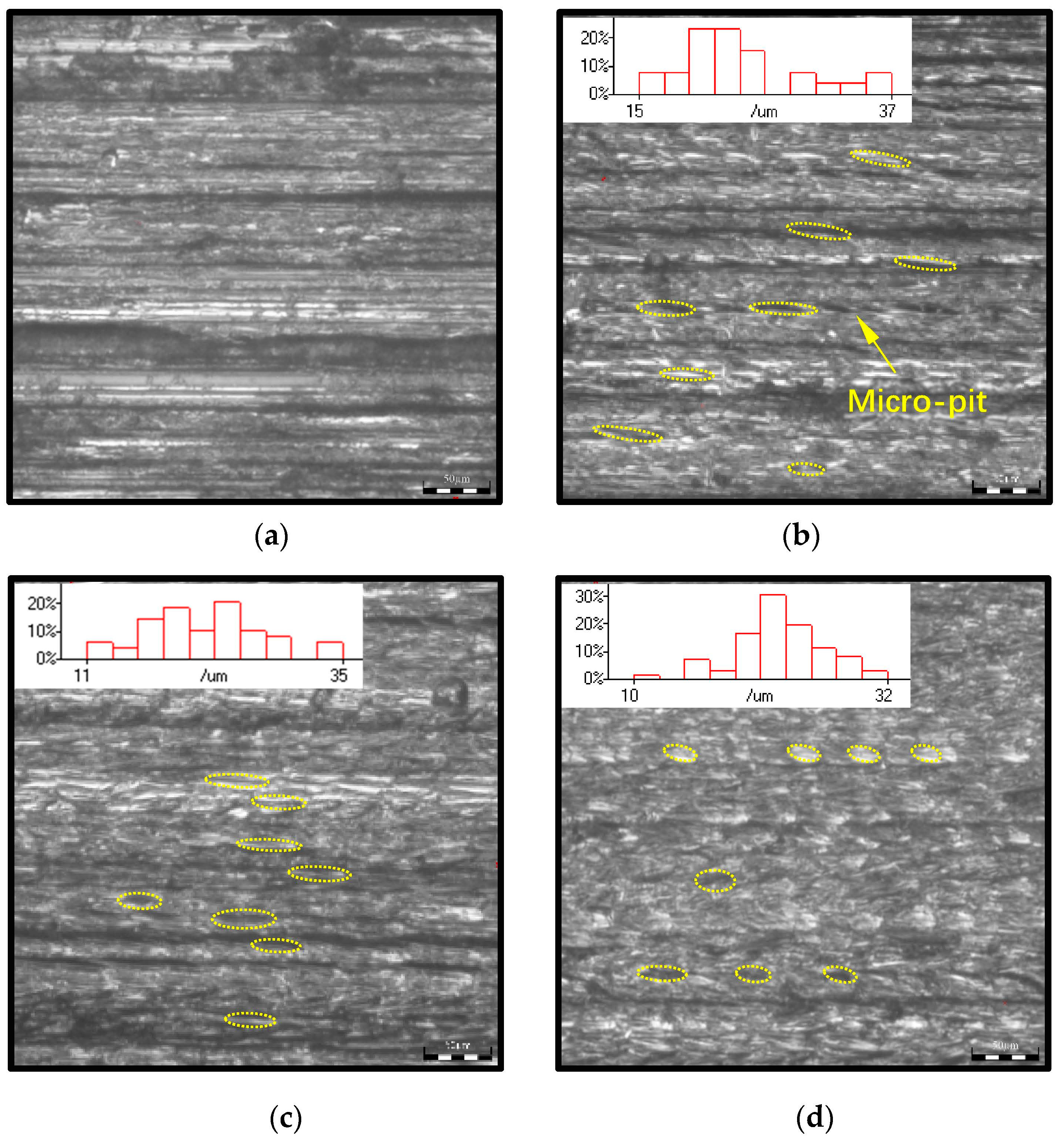
5. Experiment Results and Discussion

5.1. Influence of Amplitude

Figure 7 shows the surface texture comparisons in the different amplitudes, as measured using the Olympus DSX510 microscopic image analysis system. CG shown in Figure 7a has more thermal damage than the other surfaces. Compared to Figure 7b,c, Figure 7d has more thermal damage, which will increase with the amplitude increasing if it exceeds 8 μm. Therefore, the 8–10 μm amplitude is optimum to reduce thermal damage.
Contact angles of this group, as measured using the Kruss DSA30s contact angle measuring instrument, are 68.52°, 56.23°, 57.32°, and 57.39°, respectively. The 8 μm amplitude had optimal lubrication effect. When amplitude exceeds 8 μm, lubrication effect will descend with amplitude ascending.
Figure 8 shows the micro-pit comparison of a 50 um microscopic image with the length distribution results of micro-pits. In the last few seconds of practical grinding, when retracting the grinding wheel, the distance between abrasive grain and workpiece increases gradually, causing the length and depth of the micro-pit to decrease correspondingly. Therefore, longer lengths can reflect those of the micro-pit in the grinding process.
Selected statistics are 10% of the longer lengths from five different positions on the surface, compared with the theoretical data calculated in the middle position of distance u on the grinding wheel and simulated data (see Figure 9a). Experimental pit length is negatively correlated with the amplitude, which is consistent with the theoretical and simulated results. Surface roughness initially decreases and increases eventually, as shown in Figure 9b. Theoretical depth of the pit is negatively related to roughness when amplitude exceeds the optimum. Therefore, the 8–10 μm amplitude range is the optimum solution for surface properties–thermal damage, lubrication, and roughness.

5.2. Influence of Feed and Rotational Speed

For group 2, pit length, depth, and roughness increase with feed speed increase, as shown in Figure 9c,d. The result is consistent with the theory and simulation trend. Practical length range measured in the uniform pit area covers the theoretical and simulated values.
Figure 10 shows the micro-texture comparison between groups 2 and 3, as measured using the Eclipse LV100ND metallographic microscope.
For group 3, Figure 10b,d show that pit length increases significantly, depth decreases, and surface roughness decreases with increased rotational speed. When feed rate increases to 20 μm/s, the CBN coating is thermally damaged and causes direct friction between the grinding wheel body and workpiece. The presumption is that grinding a longer pit requires more continuous grinding time and further generates a large amount of heat, thereby damaging the CBN grains. Therefore, feed speed of 400# grinding grain cannot exceed 20 μm/s and 3000 rpm. In a grinding process with high feed speed, a large diameter grain should be selected, which will also result in a different surface performance.
When rotational speed is 2000 rpm, the convex and concave surfaces of the workpiece, generated by the inside and outside surfaces of the grinding wheel, are compared (see Figure 10e,f). According to theoretical calculations, pit length is negatively correlated with pressure angles and positively correlated with the radius. The experimental results showed that compared with the concave, the pit length of the convex surface descended and depth ascended because of the larger pressure angle and smaller radius. The results are consistent with the theoretical trend. The roughness of convex is worse than that of the concave.

6. Conclusions

This paper revealed the formation principle of intermittent grinding in RUAG of the conical grinding wheel. Radial vibration causes the microscopic grinding depth to change alternatingly. Therefore, there is an alternating separation between abrasive grain and workpiece. Grinding starts when grinding depth is positive and stops when grinding depth is negative to form the micro-pits. Furthermore, this study proposes the intermittent grinding condition of the conical grinding wheel.
The current paper also designed the equation to solve grinding depth on the basis of the theory that the volume of micro-debris is equal to that of the macroscopic removal material. Based on the grinding depth, the paper built the relationship between machining parameters and the micro-texture feature parameters. According to the RSA results, amplitude is the critical influencing factor for grinding depth. Moreover, grinding depth is reduced with increasing amplitude because increased amplitude will increase the material removal rate. The micro-pit’s depth increases with increasing feed speed or amplitude. Lastly, the micro-pit’s length increases with increasing feed speed or rotation speed.
This paper offered a 3D FEM method to simulate the micro-texture formation mechanism in RUAG. The simulation performed a single-factor experiment of machining parameters to verify the theoretical micro-texture feature parameters. The results were consistent with the theoretical ones. Moreover, the simulation of micro-texture provided a three-dimensional micro-pit structure for further research of surface properties.
The experiment proved that compared with CG, RUAG promoted surface properties, including thermal damage, lubrication, and roughness. The experimental results of the three groups showed that 8–10 um amplitude is optimal for roughness, thermal damage, and lubrication for 400# abrasive gain with decomposed radial amplitude that is 1/3 of the longitudinal one.
Compared with other radial vibrations, radial amplitude is easily optimized by adjusting the conical angle in the conical grinding wheel, which is adaptable for the different grinding wheels. This method is adaptable in grinding spiral bevel gear, worm gear, and other grinding surfaces.

Author Contributions

Conceptualization, J.H.; methodology, J.H.; validation, Y.J. and X.L.; formal analysis, X.L.; investigation, Y.J.; writing—original draft preparation, J.H.; writing—review and editing, Y.J. and J.H.; visualization, Y.J. and X.L.; supervision, Q.L.; project administration, J.H.; and funding acquisition, J.H. All authors have read and agreed to the published version of the manuscript.

Funding

This research was supported financially by the Natural Science Foundation of Tianjin, China (No. 19JCYBJC19200).

Data Availability Statement

All data are contained within the article, and fully available without restriction.

Conflicts of Interest

The authors declare no conflict of interest.

References

  1. Litvin, F.L.; Wang, A.G.; Handschuh, R.F. Computerized generation and simulation of meshing and contact of spiral bevel gears with improved geometry. Comput. Methods Appl. Mech. Eng. 1998, 158, 35–64. [Google Scholar] [CrossRef]
  2. Vimercati, M. Mathematical model for tooth surfaces representation of face-hobbed hypoid gears and its application to contact analysis and stress calculation. Mech. Mach. Theory 2007, 42, 668–690. [Google Scholar] [CrossRef]
  3. Uhlmann, E.; Spur, G. Surface Formation in Creep Feed Grinding of Advanced Ceramics with and without Ultrasonic Assistance. CIRP Ann. 1998, 47, 249–252. [Google Scholar] [CrossRef]
  4. Gao, G.F.; Zhao, B.; Xiang, D.H.; Kong, Q.H. Research on the surface characteristics in ultrasonic grinding nano-zirconia ceramics. J. Mater. Process. Technol. 2009, 209, 32–37. [Google Scholar] [CrossRef]
  5. Zhao, B.; Liu, C.S.; Gao, G.F.; Jiao, F. Surface characteristics in the ultrasonic ductile honing of ZrO2 ceramics using coarse grits. J. Mater. Process. Technol. 2002, 123, 54–60. [Google Scholar]
  6. Tawakoli, T.; Azarhoushang, B. Influence of ultrasonic vibrations on dry grinding of soft steel. Int. J. Mach. Tools Manuf. 2008, 48, 1585–1591. [Google Scholar] [CrossRef]
  7. Mohsen, G.N.; Mohammad, R.; Movahhedy, J.A. Ultrasonic-Assisted Grinding of Ti6Al4V Alloy. Procedia CIRP 2012, 1, 353–358. [Google Scholar]
  8. Zeng, W.M.; Li, Z.C.; Pei, Z.J.; Treadwell, C. Experimental observation of tool wear in rotary ultrasonic machining of advanced ceramics. Int. J. Mach. Tools Manuf. 2005, 45, 1468–1473. [Google Scholar] [CrossRef]
  9. Wu, Y.B.; Yokoyama, S.; Sato, T.; Lin, W.M.; Tachibana, T. Development of a new rotary ultrasonic spindle for precision ultrasonically assisted grinding. Int. J. Mach. Tools Manuf. 2009, 49, 933–938. [Google Scholar] [CrossRef]
  10. Liang, Z.Q.; Wu, Y.B.; Wang, X.B.; Zhao, W.X. A new two-dimensional ultrasonic assisted grinding (2D-RUAG) method and its fundamental performance in monocrystal silicon machining. Int. J. Mach. Tools Manuf. 2010, 50, 728–736. [Google Scholar] [CrossRef]
  11. Liang, Z.Q.; Wang, X.B.; Wu, Y.B.; Xie, L.J.; Jiao, L.; Zhao, W.X. Experimental study on brittle–ductile transition in elliptical ultrasonic assisted grinding (ERUAG) of monocrystal sapphire using single diamond abrasive grain. Int. J. Mach. Tools Manuf. 2013, 71, 41–51. [Google Scholar] [CrossRef]
  12. Wang, Y.; Bin, L.; Cao, X.Y.; Wang, S.L. An experimental investigation of system matching in ultrasonic vibration assisted grinding for titanium. J. Mater. Process. Technol. 2014, 214, 1871–1878. [Google Scholar] [CrossRef]
  13. Egashira, K.; Kumagai, R.; Okina, R.; Yamaguchi, K.; Ota, M. Drilling of microholes down to 10 μm in diameter using ultrasonic grinding. Precis. Eng. 2014, 38, 605–610. [Google Scholar] [CrossRef]
  14. Ning, F.D.; Cong, W.L.; Pei, Z.J.; Treadwell, C. Rotary ultrasonic machining of CFRP: A comparison with grinding. Ultrasonics 2016, 66, 125–132. [Google Scholar] [CrossRef] [Green Version]
  15. Wang, H.; Hu, Y.B.; Cong, W.L.; Hu, Z.L. A mechanistic model on feeding directional cutting force in surface grinding of CFRP composites using rotary ultrasonic machining with horizontal ultrasonic vibration. Int. J. Mech. Sci. 2019, 155, 450–460. [Google Scholar] [CrossRef]
  16. Yang, Z.C.; Zhu, L.D.; Ni, C.B.; Ning, J.S. Investigation of surface topography formation mechanism based on abrasive workpiece contact rate model in tangential ultrasonic vibration assisted CBN grinding of ZrO2 ceramics. Int. J. Mech. Sci. 2019, 155, 66–82. [Google Scholar] [CrossRef]
  17. Xu, W.X.; Wu, Y.B. A novel approach to fabricate high aspect ratio micro-rod using ultrasonic vibration-assisted centreless grinding. Int. J. Mech. Sci. 2018, 141, 21–30. [Google Scholar] [CrossRef]
  18. Li, C.; Zhang, F.H.; Meng, B.B.; Liu, L.F.; Rao, X.S. Material removal mechanism and grinding force modelling of ultrasonic vibration assisted grinding for SiC ceramics. Ceram. Int. 2017, 43, 2981–2993. [Google Scholar] [CrossRef]
  19. Wei, S.L.; Zhao, H.; Jing, J.T. Investigation on three-dimensional surface roughness evaluation of engineering ceramic for rotary ultrasonic grinding machining. Appl. Surf. Sci. 2015, 357, 139–146. [Google Scholar] [CrossRef]
  20. Wang, Q.Y.; Zhao, W.X.; Liang, Z.Q.; Wang, X.B.; Zhou, T.F.; Wu, Y.B.; Jiao, L. Investigation of diamond wheel topography in Elliptical Ultrasonic Assisted Grinding (ERUAG) of monocrystal sapphire using fractal analysis method. Ultrasonics 2018, 84, 87–95. [Google Scholar] [CrossRef]
  21. Ye, L.Z.; Zhu, X.J.; Wang, L.J.; Guo, C. Study on characteristics of single cavitation bubble considering condensation and evaporation of kerosene steam under ultrasonic vibration honing. Ultrason. Sonochem. 2018, 40, 988–994. [Google Scholar] [CrossRef]
  22. Wdowwik, R.; Porzycki, J.; Magdziak, M. Measurements of Surface Micro-structure Parameters after Ultrasonic Assisted and Conventional Grinding of ZrO2 Based Ceramic Material Characterized by Different States of Sintering. Procedia CIRP 2017, 62, 293–298. [Google Scholar] [CrossRef]
  23. Guo, B.; Zhao, Q.L. Ultrasonic vibration assisted grinding of hard and brittle linear micro-structured surfaces. Precis. Eng. 2017, 48, 98–106. [Google Scholar] [CrossRef]
  24. Zheng, F.F.; Kang, R.K.; Dong, Z.G.; Guo, J.; Liu, J.T.; Zhang, J.T. A theoretical and experimental investigation on ultrasonic assisted grinding from the single-grain aspect. Int. J. Mech. Sci. 2018, 148, 667–675. [Google Scholar] [CrossRef]
  25. Wen, Y.Q.; Tang, J.Y.; Zhou, W.; Zhu, C.C. Study on contact performance of ultrasonic-assisted grinding surface. Ultrasonics 2019, 91, 193–200. [Google Scholar] [CrossRef]
  26. Qin, S.Q.; Zhu, L.; Hao, Y.P.; Shi, C.L.; Wang, S.F.; Yang, Z.C. Theoretical and experimental investigations of surface generation induced by ultrasonic assisted grinding. Tribol. Int. 2023, 179, 108120. [Google Scholar] [CrossRef]
  27. Jiang, J.L.; Sun, S.F.; Wang, D.X.; Yang, Y.; Liu, X.F. Surface texture formation mechanism based on the ultrasonic vibration-assisted grinding process. Int. J. Mach. Tools Manuf. 2020, 156, 103595. [Google Scholar] [CrossRef]
  28. Wang, Y.; Guangheng, D.Y.; Zhao, J.N.; Dong, Y.H.; Zhang, X.F.; Jiang, X.M.; Lin, B. Study on key factors influencing the surface generation in rotary ultrasonic grinding for hard and brittle materials. J. Manuf. Process. 2019, 38, 549–555. [Google Scholar] [CrossRef]
  29. Zhao, B.; Guo, X.C.; Bie, W.B.; Chang, B.Q.; Zhao, C.Y. Thermo-mechanical coupling effect on surface residual stress during ultrasonic vibration-assisted forming grinding gear. J. Manuf. Process. 2020, 59, 19–32. [Google Scholar] [CrossRef]
  30. Zhou, W.H.; Tang, J.Y.; Shao, W. Modelling of surface micro-structure and parameters matching considering the interaction of multiple rotation cycles in ultrasonic assisted grinding. Int. J. Mech. Sci. 2020, 166, 105246. [Google Scholar] [CrossRef]
  31. Wang, Q.Y.; Liang, Z.Q.; Wang, X.B.; Bai, S.W.; Yeo, S.H.; Jia, S. Modelling and analysis of generation mechanism of micro-surface topography during elliptical ultrasonic assisted grinding. J. Mater. Process. Technol. 2020, 279, 116585. [Google Scholar] [CrossRef]
Figure 1. RUAG setup and experiment: (a) RUAG setup and (b) grinding experiment.
Machines 11 00428 g001
Figure 2. RUAG kinematic models: (a) grinding wheel model, (b) abrasive grain’s trajectory, (c) abrasive grain model, and (d) micro-pit model.
Machines 11 00428 g002
Figure 3. RSA of the relative parameters: (a) V s n h p , (b) V s A h p , (c) n A h p , (d) V s A l s , (e) V s A d , and (f) V s A A p .
Machines 11 00428 g003
Figure 4. Geometries and Meshes: (a) grinding wheel, (b) abrasive gain, and (c) workpiece.
Machines 11 00428 g004
Figure 5. Simulated micro-pit of group 1: (a) A = 0, (b) A = 8 μm, (c) A = 10 μm, and (d) A = 12 μm.
Machines 11 00428 g005
Figure 6. Simulation result comparisons of groups 2 and 3: (a) n = 2000   R P M , V s = 1   μ m / s , (b) n = 3000   R P M , V s = 1   μ m / s , (c) n = 2000   R P M , V s = 10   μ m / s , (d) n = 3000   R P M , V s = 10   μ m / s , (e) n = 2000   R P M , V s = 20   μ m / s , (f) n = 3000   R P M , V s = 20   μ m / s , (g) n = 2000   R P M , V s = 30   μ m / s and (h) n = 3000   R P M , V s = 30   μ m / s .
Machines 11 00428 g006
Figure 7. Surface texture comparison of group 1: (a) A = 0 , (b) A = 8   μ m , (c) A = 10   μ m , and (d) A = 12   μ m .
Machines 11 00428 g007
Figure 8. Micro-texture comparison of group 1: (a) A = 0, (b) A = 8 μm, (c) A = 10 μm, and (d) A = 12 μm.
Machines 11 00428 g008
Figure 9. Micro-texture comparisons of groups 1 and 2: (a) A R a A p of group 1, (b) A l s of group 1, (c) V s R a A p of group 2, and (d) V s l s of group 2.
Machines 11 00428 g009
Figure 10. Experimental micro-pit comparisons: (a) n = 2000   R P M , V s = 10   μ m / s , (b) n = 2000   R P M , V s = 20   μ m / s , (c) n = 2000   R P M , V s = 30   μ m / s , (d) n = 3000   R P M , V s = 10   μ m / s , (e) n = 3000   R P M , V s = 20   μ m / s , and (f) n = 2000   R P M , V s = 10   μ m / s , convex.
Machines 11 00428 g010
Table 1. Grinding wheel’s dimensions.
ParametersValues
Wheel diameter (mm)60.00
Outside pressure angle (°)17.92
Inside pressure angle (°)22.08
Point width (mm)0.73
Outside edge radius (mm)0.50
Inside edge radius (mm)0.50
Mean radius (mm)23.14
Table 2. Material properties.
Material
Properties
Workpiece
(45# Steel)
Grain (CBN)
Density ( k g / m 3 )785015,700
Elastic modulus (GPa)210705
Poisson’s ratio0.330.23
Specific heat capacity ( J / ( k g · ° C ) )526.3178
Thermal conductivity ( w / ( m · ° C ) )6.724
Linear expansion coefficient ( 10 6 / ° C )95
Table 3. Machining parameters of the experiment.
GroupsAmplitude
( μ m )
Feed Speed
( μ m / s )
Rotational Speed
(rpm)
10/8/10/1213000
281/10/20/302000
381/10/20/303000
Table 4. Micro-pit dimension comparison of Group 1.
Amplitude A
( μ m )
Theoretical Length l s ( μ m ) Theoretical Depth A p
( μ m )
Theoretical Spacing d
( μ m )
Simulated Length l s
( μ m )
Grinding Depth h p
( μ m )
0-0.00631.787-0.006
835.2150.09831.35939.51−2.363
1032.6630.10631.32536.153−2.971
1230.7170.11231.29633.186−3.580
Table 5. Micro-pit dimension comparison of Group 2.
Feed Speed
V s
( μ m / s )
Theoretical Length l s ( μ m ) Theoretical Depth A p
( μ m )
Theoretical Spacing d
( μ m )
Simulated Length l s
( μ m )
Grinding Depth h p
( μ m )
126.8500.12831.22432.260−2.333
1057.0380.55929.27562.500−1.902
2071.3070.85327.94978.620−1.609
3081.2101.08426.90485.680−1.378
Table 6. Micro-pit dimension comparison of Group 3.
Feed Speed
V s
( μ m / s )
Theoretical Length l s ( μ m ) Theoretical Depth A p
( μ m )
Theoretical Spacing d
( μ m )
Simulated Length l s
( μ m )
Grinding Depth h p
( μ m )
135.2150.09846.66046.660−2.363
1074.9510.43582.06082.060−2.027
2093.3710.668100.790100.790−1.794
30106.7720.854114.170114.170−1.608
Disclaimer/Publisher’s Note: The statements, opinions and data contained in all publications are solely those of the individual author(s) and contributor(s) and not of MDPI and/or the editor(s). MDPI and/or the editor(s) disclaim responsibility for any injury to people or property resulting from any ideas, methods, instructions or products referred to in the content.

