
Dynamic Simulation of Multiple Launch Rocket System Marching Fire Based on the Fuzzy Adaptive Sliding Mode Control

College of Mechanica Engineering, North University of China, Taiyuan 030051, China
*
Author to whom correspondence should be addressed.
Machines 2023, 11(4), 427; https://doi.org/10.3390/machines11040427
Submission received: 14 February 2023
/
Revised: 17 March 2023
/
Accepted: 24 March 2023
/
Published: 27 March 2023
Abstract
:This paper presents a servo control method for the multiple launch rocket system (MLRS) launcher during marching fire operations. The MLRS, being a complex nonlinear system, presents challenges in designing its servo controller. To address this, we introduce the fuzzy adaptive sliding mode control (FASMC) approach. The permanent magnet synchronous motor (PMSM) and controller of the MLRS were simulated in the MATLAB/Simulink environment. The dynamic model of the MLRS during marching fire was established using multi-body system theory, vehicle mechanics, and launch dynamics. The dynamic model was then integrated with the FASMC-based controller using the Adams/View module. Numerical calculations were performed to demonstrate the control performance and the effectiveness and applicability of the proposed approach were validated through a comparison experiment between FASMC and other common control methods.
1. Introduction
The multiple launch rocket system (MLRS) is a highly effective tactical weapon system that provides quick firepower across a wide area. As a motor-mechanical system, it can be used for various types of fire strikes, including ground-to-ground, ground-to-air, ship-to-shore, or ship-to-ship. With advancements in rocket guidance technology, there is a growing trend towards improving the maneuverability and response to marching fire from unmanned targets. However, the application of guidance technology alone is not enough to guarantee accuracy. Minimizing launch vibrations can also help reduce rocket dispersion [1], and this has become an important direction for MLRS development. In order to improve firing accuracy, reducing firing deviation during tuning and firing through dynamic control is essential. This technique has been widely used in MLRS research in recent years [2,3,4]. The MLRS marching fire process is complex and challenging due to random road incentives, variations in mass, nonlinear suspension and tire characteristics, and the instant impact during launching [5,6]. As a result, the MLRS dynamic model is nonlinear and time-varying, making it difficult to establish a reliable and accurate dynamics model and control strategy [7,8]. The main challenge is to ensure the stability and robustness of the system despite nonlinearities and uncertainties in such a complex motor-mechanical coupling system as the MLRS.
Considerable effort has been put into enhancing the stability and robustness of the control system for the MLRS, following the introduction of passive control methods [9,10,11]. Despite the benefits of passive methods in terms of control response, they have a limited ability to handle larger responses due to the lack of energy required. This can make it challenging to guarantee high-precision tracking characteristics during marching fire. proportional-integral-derivative (PID) control has become a popular choice due to its simplicity, clarity, and effectiveness, and it is currently used in fixed or semi-fixed MLRS launches [12,13,14]. However, classical PID control may not provide adequate control performance when the nonlinearity of the MLRS increases during marching fire. As a result, many researchers have attempted to design servo control systems using modern control theory. One promising approach is sliding mode control (SMC), which has been shown to be effective in controlling nonlinear systems [15,16,17,18]. SMC has the advantage of being robust to uncertainties and disturbances in the system, making it a popular choice in robot control. Despite its fast response time and resistance to external noise disturbances and parameter changes, SMC also has the drawback of “chattering,” a phenomenon caused by switching terms. Excessive chattering is not acceptable in high-precision MLRS systems [19,20].
Many intelligent algorithms are used to address uncertainties [21,22]. One such technique is a fuzzy system, which is widely utilized due to its universal approximation property [23,24,25]. In the field of robotics, J. Baek, et al. [26] proposed an adaptive sliding mode control scheme for a robot manipulator, which demonstrated considerable results through online adaptive parameter adjustments. M. O. Efe [27] applied this same control scheme to a 2 degrees of freedom robotic arm, resulting in improved tracking performance with enhanced robustness and insensitivity. S. Moussaoui, et al. [28]. proposed a fuzzy approximation-based adaptive sliding mode control for uncertain nonlinear systems with perturbations. The effectiveness and robustness of the proposed adaptive fuzzy controller were demonstrated through two simulation case studies from the underactuated system control literature. However, these studies often simplified dynamic models to linear transfer functions, leading to inaccuracies in the developed models. Additionally, the excitation generated from sources such as road, suspension, and tires was neglected or simplified, resulting in discrepancies between calculated results and actual outcomes. With the increased emphasis on the MLRS marching fire requirement, these discrepancies cannot be ignored and must be addressed in future research.
On the other hand, the control system is often overlooked in the dynamic simulation of marching fire, particularly in the context of MLRS. This lack of attention results in difficulties in accurately reflecting the control effect of rocket launchers in real-world scenarios. Some researchers have studied the controlled performance of tank marching shooting, such as Liu et al. [29], who modeled the firing dynamics of tank marching fire to understand initial disturbances but did not delve into the control system in depth. Jin et al. [30] established a multi-rigid body dynamics model and controlled the motion of the gun barrel through PID control, demonstrating its effectiveness at high speeds. Purdy et al. [31] conducted research on the impact of nonlinear friction on control performance and obtained quantitative analysis results through a nonlinear model of the electromechanical dynamic control system of a main battle tank, using PI control. Currently, intelligent algorithms in linear systems are well-studied, but simulation studies on the dynamic control of MLRS marching fire based on intelligent control methods are insufficient due to the complexity of the system and the demanding computational requirements of intelligent algorithms.
This study investigates the dynamic control of MLRS marching fire actuated by a PMSM drive using a fuzzy adaptive sliding mode control (FASMC) to enhance stability and robustness. A nonlinear model of the motor-mechanism coupling in MLRS marching fire was established. The implementation of PID or SMC controllers can result in poor control performance due to uncertainties including parametric variations and unmodeled dynamics. To address this issue, a FASMC was introduced to compensate for these uncertainties. The sliding and switching parameters of the FASMC were updated adaptively based on the Lyapunov stability theory, ensuring the asymptotic stability of the closed-loop system. The main contributions of this paper are summarized as follows.
- The co-simulation dynamic control model of the motor-mechanism coupling MLRS was established.
- The FASMC controller was developed considering the systematic nonlinearity, in which the FASMC was built to adapt to the uncertainties of the system.
- The proposed controller is first introduced and successfully applied to the field of the dynamic control for MLRS marching fire considering the occurrence of uncertainties.
The paper was structured as follows. Section 2 presents the formulation of the motor-mechanism coupling dynamic model of MLRS marching fire through co-simulation. The FASMC controller, designed to adapt to lumped uncertainty online, was formulated based on the Lyapunov stability theory in Section 3. In Section 4, simulation results and discussions were presented to validate the proposed controller. The conclusion was provided in Section 5.
2. Nonlinear Dynamic Model of MLRS Marching Fire
2.1. Mechanical System Dynamic Modeling
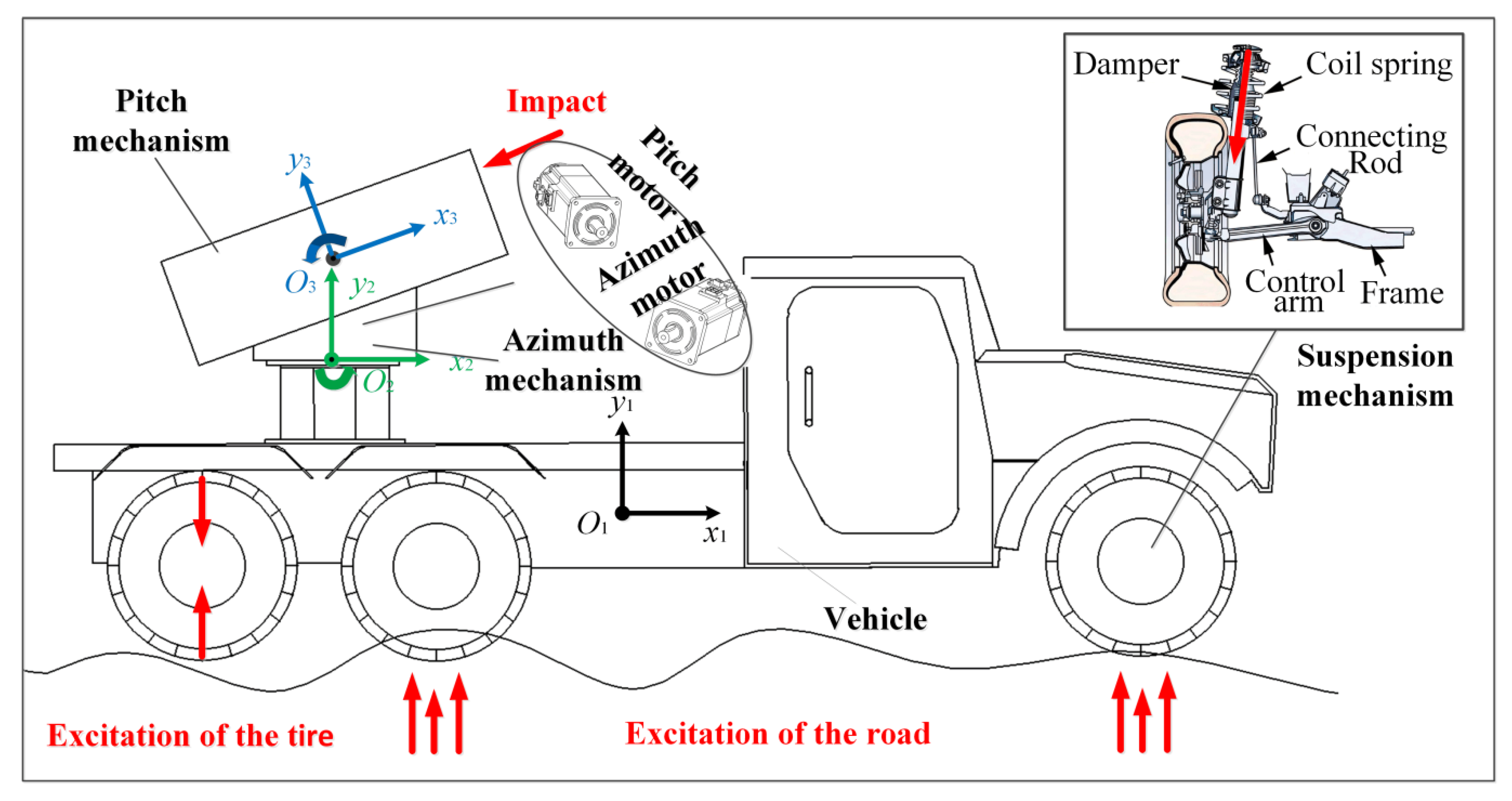
The dynamic model of the MLRS marching fire was established in this study, taking into account the complex multi-body mechanical system of the MLRS. The model abstracts the MLRS into two parts: (1) the vehicle body part, which consists of tires, suspension, vehicle beam and body, etc.; (2) the firing part, which includes the base, rotary part, pitch part, storage and transport of launch box, directional tube and rocket, etc. The suspension used in the study was a double-wishbone independent suspension, which comprises two unequal V-shaped or A-shaped control arms and a strut-type hydraulic damper. The upper control arm was connected to the damper at one end and the body at the other end; the lower control arm was connected to the wheel at one end and the body at the other end; the upper and lower control arms were connected by connecting rods. The influence of random road excitation was simulated by establishing a plate-road contact model. The schematic diagram of the dynamic model was shown in Figure 1. Moreover, the unevenness of the road surface is an important disturbance factor that has a significant effect on the accuracy of the MLRS Marching Fire, and its impact on the overall system can be estimated by analyzing the power spectrum of the road surface and the system frequency response. Additionally, the dynamic model can be used to study the dynamic characteristics of the MLRS Marching Fire under different road conditions.
It is worth noting that the MLRS multi-body dynamics model was built based on the Adams platform, including the tire model, and the suspension model. The UA model was used for the tire modeling, and its nonlinearity has been considered.
2.2. 3-D Road Roughness Model
The unevenness of the road surface is an important disturbance that has a significant impact on the accuracy of the MLRS marching fire. This disturbance affects the accuracy of the firing system when adjusting the gun control through the tires, suspension system, and vehicle body up to the firing part of the rocket launcher, and then affects the firing accuracy of the weapon system when marching fire. In order to accurately simulate the dynamic response of the overall system, the power spectrum of the road surface and the system frequency response must be calculated. In this paper, the MLRS system is considered a nonlinear system due to the existence of nonlinear components such as suspensions and springs, and thus the superposition principle applicable to linear systems is not applicable. Therefore, the unevenness reconstruction of the road surface in the time or space domain must be performed.
The power spectrum density function can be represented as [32],
where, is the spatial frequency; is the reference spatial frequency; is the pavement unevenness coefficient; is the frequency index—the slope of the slope line on the double logarithmic coordinates, it determines the frequency structure of the pavement power spectral density, generally taken as 2.
The random process of the three-dimensional road can be represented as,
where is the length in the road direction, is the amplitude of the harmonic fluctuation corresponding to the center frequency, is the inherent frequency of the vehicle vibration system, is the driving speed, is the random number in the interval of . Since the inherent frequency of the vehicle vibration system is 0.7~15 Hz and the common vehicle speed is 36~180 km/h ), the lower and upper limits of the excitation time-frequency of the ground acting on the tires are taken to be , , the upper and lower limits of the spatial frequency needed to study the vehicle vibration can be represented as,
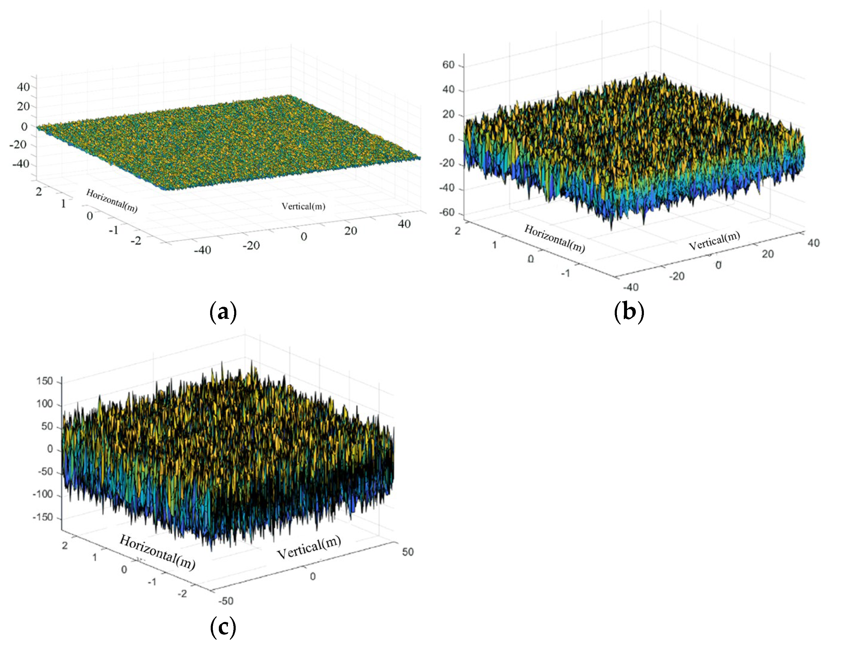
In order to analyze the robustness of the adopted control method for the MLRS marching fire under actual driving road conditions, this paper adopts the harmonic superposition method and writes a Matlab algorithm based on the harmonic superposition method to generate three kinds of pavement unevenness pavement of class A, D, and F. The three-dimensional road excitation is shown in Figure 2. Moreover, the power spectrum of the road surface can be used to estimate the impact of the road unevenness on the overall system, and the system frequency response can be calculated to further analyze the dynamic characteristics of the MLRS Marching Fire under different road conditions. Grading standard of road roughness was shown as Table 1.
2.3. Permanent Synchronous Motor Modeling
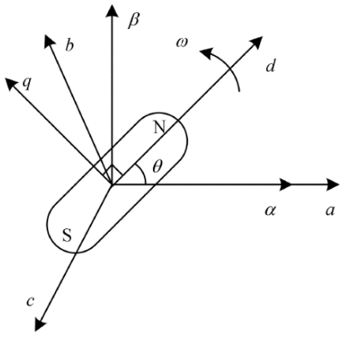
The 3-phase AC permanent magnet synchronous motor (PMSM) is widely utilized in various industrial applications due to its compact size, high efficiency, and lightweight characteristics. In this study, PMSM is selected as an actuator for dynamic control as a result of its adjustable rotor parameters and excellent control performance. However, the PMSM is time-varying, coupled, and nonlinear, making its parameters difficult to describe in a 3-phase fixed reference frame. To simplify the computational process of deriving the mathematical model of the PMSM, the coordinate system and stationary coordinate system of the PMSM are established based on the Clark and Parker transforms [33]. The surface-mounted PMSM and the field-oriented control strategy were chosen. The model of the control strategy is referred to the method of Liu et al. [34,35]. The magnetic field axis of the permanent magnet base is designated as the -axis and 90° ahead is designated as the -axis. The three-phase parameters in the fixed reference frame are transformed into two-phase parameters in the synchronous reference frame as shown in Figure 3, where ω is the speed of rotation and θ is the angular displacement of rotation.
According to Clarke and Park transform, one can obtain
where can be the arbitrary parameters of PMSM.
where is the angular displacement of rotor.
With the transformation (7), the voltage equation of PMSM in the reference frame can be expressed as,
where,
, are the component of stator voltage in the d axis, and q axis, respectively;
, are the component of stator current in the d axis, and q axis, respectively;
, are the component of stator flux in the d axis, and q axis, respectively;
is the stator resistance;
is the differential operator;
is the angular speed of rotor
The stator flux equation can be written as,
where and are the components of stator inductance in the d axis and q axis, respectively; is the permanent magnet flux.
The torque equation of PMSM is
where is the electromagnetic torque; is the number of pole pairs.
The field-oriented control technique decouples the d-axis current and the q-axis current, allowing the stator current component and the electromagnetic torque to be controlled solely through the manipulation of current magnitude. Consequently, the implementation of field-oriented control simplifies the PMSM driving system into a DC motor model. Equations (8) and (10) can be reformulated as follows:
where is the torque coefficient.
Equation of motion of the rotor is
where , and are the load torque, the damping coefficient, and the inertia of rotor, respectively.
2.4. The Co-Simulation Model of the MLRS
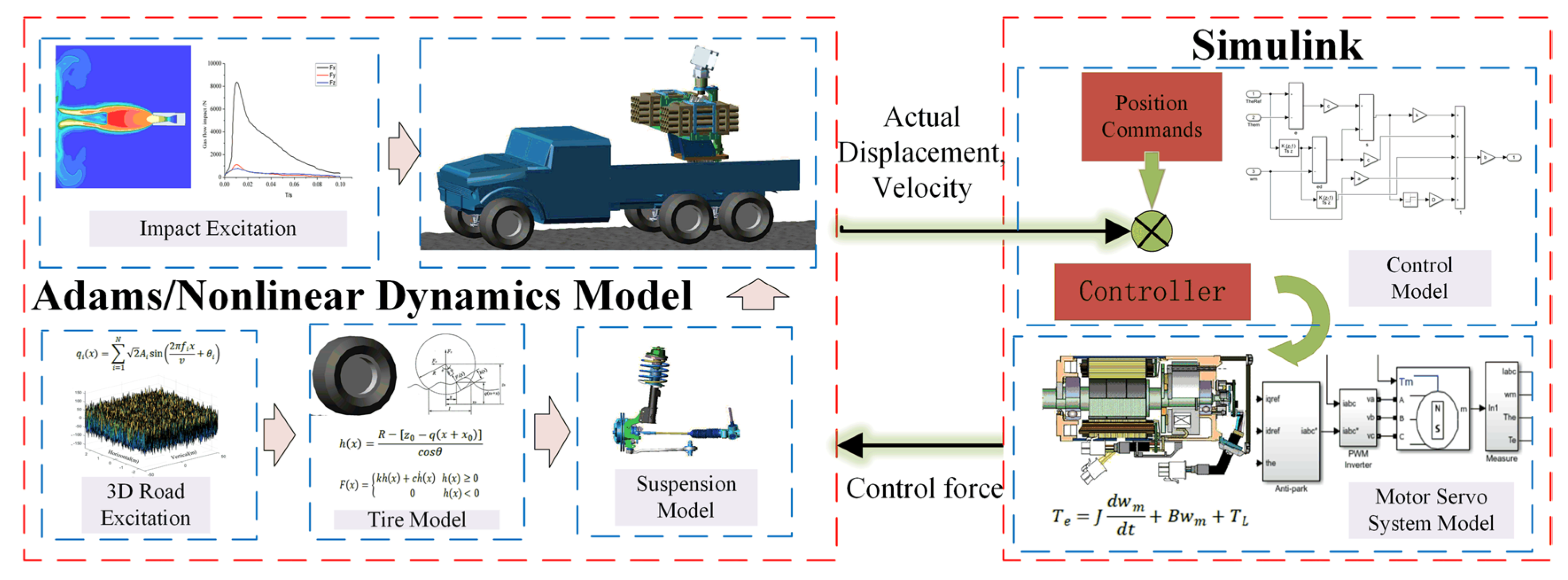
The objective of the modeling process is to construct a motor-driven servo system for the MLRS. This paper presents a co-simulation model, which is established through the integration of Adams and MATLAB/Simulink. The driving torque of the MLRS is generated by the PMSM motor. Table 2 displays the primary PMSM parameters utilized in this study.
The 3-D model of the MLRS was initially imported into Adams, where the redundant degrees of freedom were constrained using the standard hinge during modeling. The simulation of the motor force was carried out by applying torque at the motor output gear. An input state was created, which was the output control force of the power motor calculated by the motor servo system calculation model. The state variable (the output control force) was associated with the motor force and was set as the input variable of the dynamical systems. The angular displacement (obtained with velocity integral), velocity, and acceleration of the MLRS were designated as the output variables. The co-simulation interface file was then exported from the Adams/Control module. The designed controller with the control method was compiled into the S function form using the C language. The control system model was established in Simulink. The co-simulation interface file was used to integrate the multibody dynamics model as a controlled object into the control model. The established motor-mechanism co-simulation model of the MLRS marching fire is depicted in Figure 4.
3. Control System Design and Stability Analysis
3.1. Fuzzy Logic System
Fuzzy logic system is a system in which the input, output, and state variables are defined on a fuzzy set, which will be used for controller design in this paper. A fuzzy logic system can be expressed by IF-THEN rules as [36],
where is the number of fuzzy rules for each fuzzy model, and and y are the input and output of the fuzzy systems, respectively, and are fuzzy sets, respectively.
The fuzzy system with singleton fuzzification, product inference and center average defuzzification is expressed as [37],
where is the membership function of the linguistic variable , is the center point of the fuzzy set output by the jth rule.
Then, the function (16) can be rewritten as follow
where ,,.
From the nonlinear mapping ability of fuzzy logic system, there are optimal values of , such that
where is the input of fuzzy logic system, and is the function to be identified. is the estimation error of the optimal fuzzy logic system. is the fuzzy basis function, and .
Using the fuzzy logic system to identify the unknown nonlinear function, the estimated value can be written as follows,
where is the estimated value of .
According to (18) and (19), the estimated error of fuzzy logic system can be obtained as follows,
where is the estimated error of .
3.2. Design of Fuzzy Adaptive Sliding Mode Controller
The controlled object of the MLRS servo system is the PMSM, and the PMSM state equation can be described as [38],
where , θ is the pitch angular displacement; ϕ is the rotation angular displacement is the coefficient of viscous friction; is the rotational inertia; is the electromagnetic torque coefficient; is the input of the motor; is the uncertain disturbances, including the effect from the road, tires and suspension.
Expressed in angular quantities as,
where , ; and , is a positive real number. = . is the actual value of MLRS, and is the expected value.
By choosing the deviation between the target command and the actual feedback value as the control quantity, the error can be described as,
Define the integral sliding surface as,
Sliding motion existence condition,
Then,
By determining , the tracking error will converge to zero.
Substituting Equation (22) into Equation (26) yields the system control law as
Equation (27) is the ideal control law, where A and B are deterministic parameters and is a deterministic disturbance. However, A, B, and are uncertain in the real servo system, because the rotational inertia changes in the process of the MLRS marching fire, and there are errors in the parameters related to the motor in practical applications, road excitation, and gas jet impact are random. Therefore, the system cannot achieve the ideal control law. In this paper, FASMC control is used to achieve the approximation of the ideal control law.
The fuzzy system is described as,
where, . The PMSM parameters in the simulation model are the same as Section 2.4., and the affiliation function of the system output is chosen as,
According to the fuzzy approximation principle, there exists an optimal fuzzy system to approximate .
where is the approximation error and satisfies .
The estimate of is taken to be , due to the unknown parameters of the fuzzy system,
then,
The error existing between the ideal control law and the optimal fuzzy system output control quantity can be compensated by the switching control . The total control law is expressed as,
According to Equation (32), define
Then,
Transforming the above equation yields,
Substituting Equation (33) into Equation (38) yields,
According to stability theory, the Lyapunov function is defined as [39],
where is a positive constant.
Then,
According to the stability condition, . The adaptive law is designed as,
The value of switching gain will directly affect the system chatter, in practice, often take the value empirically, if the gain value is too large, it will produce large chatter, on the contrary, the control system is unstable, so the switching gain also has uncertainty, this paper to adaptive way to select the gain.
Using instead of , Equation (43) transforms to,
where is the estimated switching gain.
Define the estimation error as and define the closed-loop system Lyapunov function as,
where , are positive real numbers to ensure system stability. And the values of , , , , comply with the Hurwitz criterion.
Derivation of Equation (46),
To make < 0, the adaptive law is designed such as,
Then,
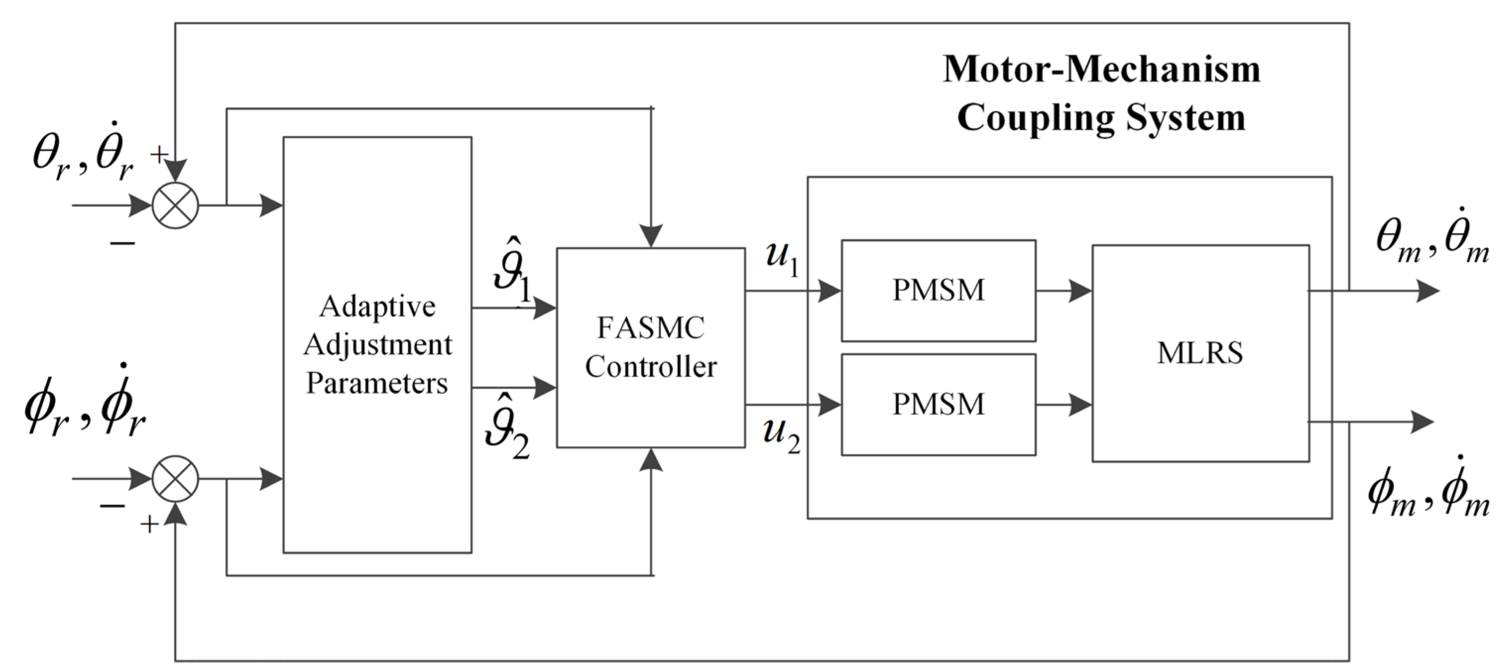
The MLRS is a complex nonlinear system that is also affected by random excitation from tires, suspensions, and road surfaces, especially during the marching firing process. The closed-loop control approach of the deterministic system has been difficult to be applied on this system. The objective of the proposed fuzzy adaptive sliding mode control is to adjust the control parameters online to adapt to the variation of excitation. Figure 5 shows the closed-loop control process of the electro-mechanical coupled system with FASMC. The command signal is input, the parameters are adaptively adjusted after the error calculation, and the FASMC controller solves the output theoretical speed and is executed by the PMSM to achieve the angle adjustment.
4. Simulation and Analysis
In the simulations conducted, similar initial conditions were utilized. The initial static equilibrium speed of the MLRS was set to 0 and the vehicle was driven at a speed of 30 km/h under three-stage road driving conditions (A, D, and F). A command signal was added after the vehicle was driven at a uniform speed for 0.5 s and the driving disturbance was addressed in real-time through the road excitation dynamics model. The rocket launch was triggered at t = 3 s, with the gas jet impact force added as an impact load.
To meet actual combat requirements, the command signal for the MLRS position servo action was divided into a step signal and a sine tracking signal. The proposed FASMC was compared with two widely used control methods, PID control and SMC, to evaluate its accuracy and robustness. The expressions of PID and SMC are, respectively,
where, is the proportional, integral, and differential gain, respectively.
The parameters were adjusted by parameter testing to ensure that the PID and SMC parameters were optimal. The control system parameters were obtained as shown in Table 3.
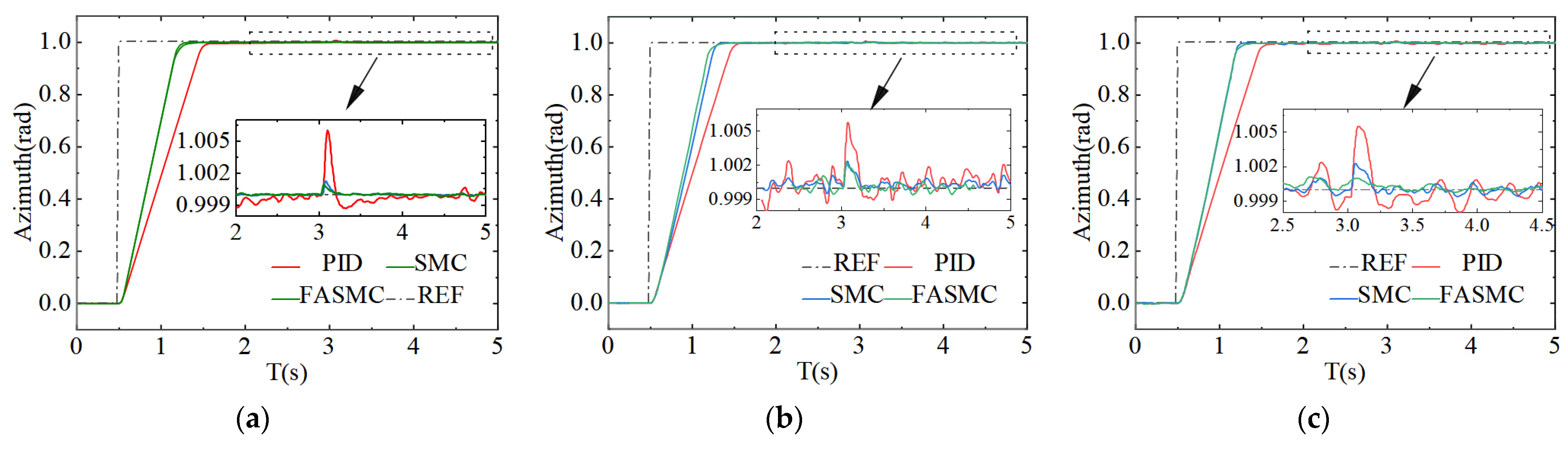
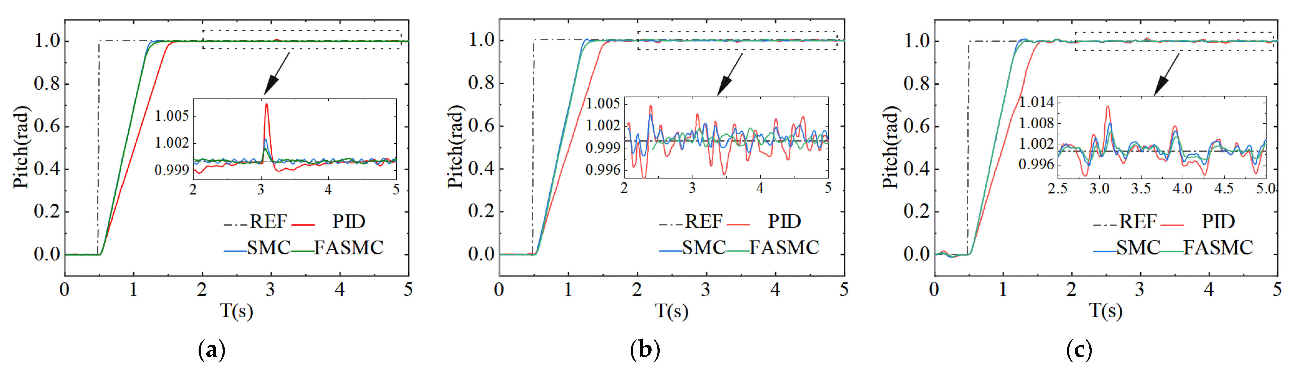
Figure 6 and Figure 7 and Table 4 indicate that in terms of adjustment time, both SMC and FASMC have similar results at 0.7 s on Class A pavement, which is a 30% improvement compared to PID control’s regulation time of 1.03 s. The FASMC demonstrates higher robustness to various degrees of road unevenness, with its adjustment time staying around 0.75 for Class D and Class F pavements, while SMC’s adjustment time increases to 0.8 s as the pavement condition worsens. This trend is also observed for steady-state error and impact disturbance. Despite the worst working condition in Class F pavement, FASMC still demonstrates good accuracy and robustness, with a maximum steady-state error reduction of 49% and 34% for PID and SMC respectively, and a 67% and 39% reduction in impact disturbance for PID and SMC respectively.
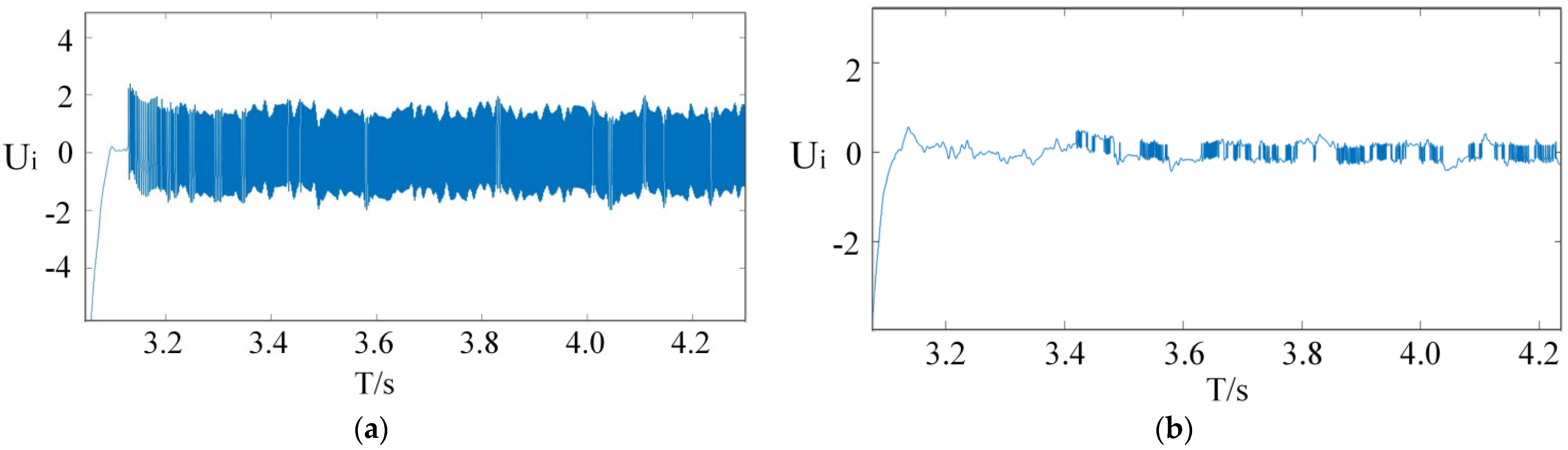
The SMC has inherent chattering characteristics. As shown in Figure 8, the FASMC effectively reduces the chattering phenomenon of sliding mode control. The chattering amplitude has been reduced from 2 to 0.5, and the chattering frequency has been significantly reduced, resulting in lower demands on motor performance.
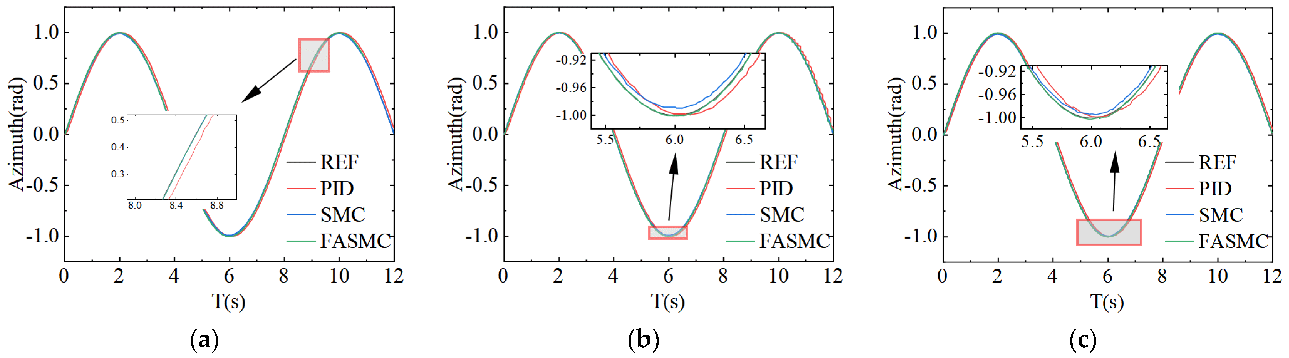
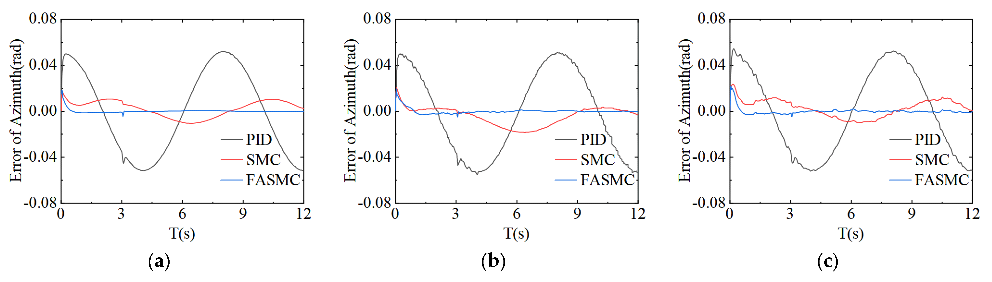
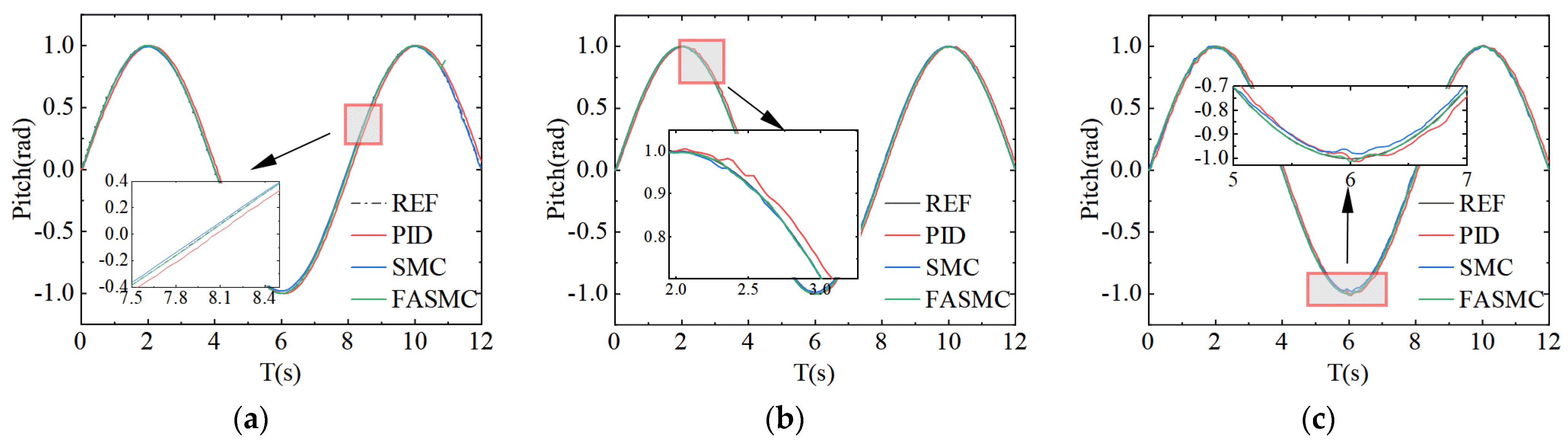
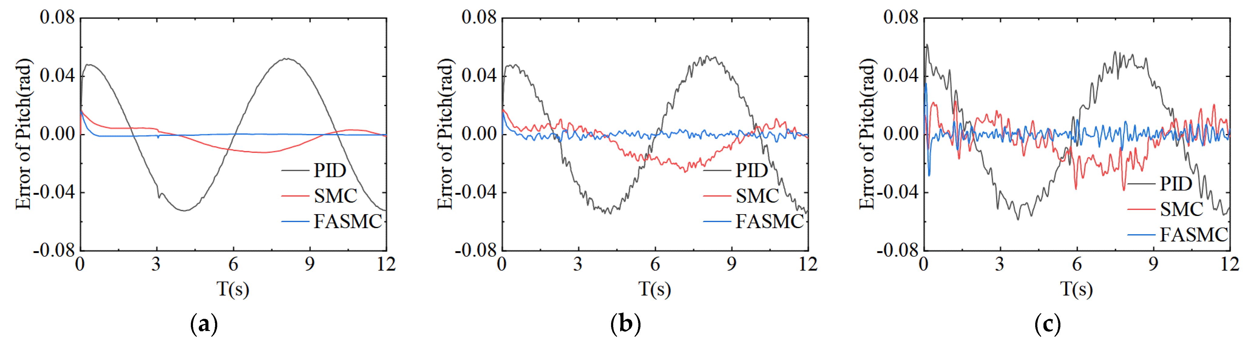
As depicted in Figure 9, Figure 10, Figure 11 and Figure 12, the tracking error of FASMC in sine signal was significantly lower compared to that of PID and SMC. During A-class road conditions, FASMC has a small road excitation, but it requires an initial self-adaptive process. The tracking error starts at around 20 mils, but once stabilization, the sine tracking error can be effectively reduced to within 4 mils. The random excitation amplitude and uncertainty in road conditions of classes D and F present a challenge to the tracking error, but the tracking accuracy remains acceptable with an error controlled within 10 mils. These results demonstrate the feasibility of using FASMC.
5. Conclusions
This paper addresses the problems of poor precision and weak robustness of MLRS marching fire, and fully considers the characteristics of uncertain parameters and strong randomness. A motor-mechanism coupling dynamic model of MLRS marching fire was established and a FASMC controller was designed using the co-simulation method. The multiple parameter uncertainties of the system were fully considered and the fuzzy logic system was used to improve the stability and robustness of the system. The dynamic characteristic of MLRS marching fire under the control of the servo system was studied by the co-simulation method based on the Adams/View module and MATLAB/Simulink. The following conclusions were obtained:
- (1)
- FASM demonstrates superior robustness and accuracy in commanding signals. In comparison to PID control, the adjustment time was reduced by 30% and compared to SMC, it was reduced by 6.2%. Additionally, the steady-state error and shock disturbance were decreased by 49% and 67%, respectively, in comparison to PID control and by 34% and 39%, respectively, in comparison to SMC.
- (2)
- FASMC significantly improved the chatter characteristics of SMC, reducing the frequency of chatter and decreasing the amplitude by 75% compared to SMC.
- (3)
- FASMC also significantly improved the tracking accuracy of MRLS, controlling the tracking error under F-level pavement excitation within 10 mils, resulting in a performance improvement of 74% over PID control and 50% over SMC control. The study found that under Class D and F pavements, pavement excitation exceeded impact disturbance as the main factor affecting accuracy.
Author Contributions
Conceptualization, Q.L. and P.Q.; software, Z.S.; validation, J.Z., P.L. and D.Z.; writing—original draft preparation, Z.S.; writing—review and editing, P.Q.; All authors have read and agreed to the published version of the manuscript.
Funding
The work described in this paper was supported by the research grants from the National Defense Pre-Research Foundation of China (Grant No. 6141B02040203).
Data Availability Statement
Not applicable.
Conflicts of Interest
The authors have no competing interests to declare that are relevant to the content of this article.
References
- Rui, X.T.; Lu, Y.; Wang, G.; Chen, W.; Yun, L. Simulation and Test Methods of Launch Dynamics of Multiple Launch Rocket System; National Defence Industry Press: Beijing, China, 2003. [Google Scholar]
- Dziopa, Z.; Koruba, Z. The impact of launcher turret vibrations control on the rocket launch. Bull. Pol. Acad. Sci. Tech. Sci. 2015, 63, 717–728. [Google Scholar] [CrossRef]
- Li, B.; Rui, X.; Wang, G. A simplified dynamic model and control for a multiple launch rocket system. J. Vib. Control 2021, 28, 2288–2300. [Google Scholar] [CrossRef]
- Li, B.; Rui, X.; Tian, W.; Cui, G. Neural-network-predictor-based control for an uncertain multiple launch rocket system with actuator delay. Mech. Syst. Signal Process. 2020, 141, 106489. [Google Scholar] [CrossRef]
- Li, B.; Rui, X.; Wang, G.; Zhang, J.; Zhou, Q. On Modeling and Dynamics of a Multiple Launch Rocket System. Proc. Inst. Mech. Eng. Part G J. Aerosp. Eng. 2021, 235, 1664–1684. [Google Scholar] [CrossRef]
- Ding, Y.; Zhou, K.; He, L.; Zhang, J.; Yang, H. Dynamic Simulation and Experiment of Marching Small Unmanned Ground Vehicles with Small Arms. Arab. J. Sci. Eng. 2022, 79, 1–15. [Google Scholar] [CrossRef]
- Gu, L.; Rui, X.; Wang, G.; Yang, F.; Wei, M. A Novel Vibration Control System Applying Annularly Arranged Thrusters for Multiple Launch Rocket System in Launching Process. Shock Vib. 2020, 2020, 7040827. [Google Scholar] [CrossRef]
- Li, C.; Wang, X.; Sun, Q.; Yang, G. Adaptive Robust Control of Muzzle Vibration for Marching Tank Based on Disturbance Observer. In Proceedings of the 2022 International Conference on Advanced Robotics and Mechatronics (ICARM), Guilin, China, 9–11 July 2022; pp. 854–859. [Google Scholar]
- Cochran, J.E., Jr.; Gunnels, R.T.; McCutchen, R.K., Jr. Rocket Launchers as Passive Controllers (DTIC Document); U.S. Army Missile Command, Redstone Arsenal: Huntsville, AL, USA, 1981. [Google Scholar]
- Zhao, W.; Chen, G. Rocket passive control. Acta Armamentarii 1996, 17, 40–45. [Google Scholar]
- Wang, R.; Lu, B.; Hou, Y.; Gao, Q. Passivity-based control for rocket launcher position servo system based on improved active disturbance rejection technology. Adv. Mech. Eng. 2018, 10, 3. [Google Scholar] [CrossRef] [Green Version]
- Dokumaci, K.; Aydemir, M.T.; Salamci, M.U. Modeling, PID Control and Simulation of a Rocket Launcher System. In Proceedings of the 16th International Power Electronics and Motion Control Conference and Exposition, Antalya, Turkey, 21–24 September 2014. [Google Scholar]
- Hu, J.; Ma, D.; Guo, Y. Optimal PID Position Controller of Multi-Rocket Launcher Using Improved Elman Network. In Proceedings of the 8th World Congress on Intelligent Control and Automation, Jinan, China, 7–9 July 2010. [Google Scholar]
- Li, B.; Rui, X.; Zhou, Q. Study on simulation and experiment of control for multiple launch rocket system by computed torque method. Nonlinear Dyn. 2017, 91, 1639–1652. [Google Scholar] [CrossRef]
- Chen, F.; Ma, D.; Yang, F. Backstepping Sliding Mode Control for Rocket Launcher Alternating Current Servo System. Adv. Mater. Res. 2012, 490–495, 1387–1391. [Google Scholar] [CrossRef]
- Mohd Zaihidee, F.; Mekhilef, S.; Mubin, M. Robust Speed Control of PMSM Using Sliding Mode Control (SMC)—A Review. Energies 2019, 12, 9. [Google Scholar] [CrossRef] [Green Version]
- Mu, C.; He, H. Dynamic Behavior of Terminal Sliding Mode Control. IEEE Trans. Ind. Electron. 2018, 65, 3480–3490. [Google Scholar] [CrossRef]
- Tong, D.; Xu, C.; Chen, Q.; Zhou, W. Sliding mode control of a class of nonlinear systems. J. Frankl. Inst. 2020, 357, 1560–1581. [Google Scholar] [CrossRef]
- Yu, X.; Feng, Y.; Man, Z. Terminal Sliding Mode Control—An Overview. IEEE Open J. Ind. Electron. Soc. 2021, 2, 36–52. [Google Scholar] [CrossRef]
- Soon, C.C.; Ghazali, R.; Ghani, M.F.; Shern, C.M.; Sam, Y.M.; Has, Z. Chattering Analysis of an Optimized Sliding Mode Controller for an Electro-Hydraulic Actuator System. J. Robot. Control 2022, 3, 2. [Google Scholar] [CrossRef]
- Dong, H.; Yang, X.; Gao, H.; Yu, X. Practical Terminal Sliding-Mode Control and Its Applications in Servo Systems. IEEE Trans. Ind. Electron. 2023, 70, 752–761. [Google Scholar] [CrossRef]
- Feng, H.; Song, Q.; Ma, S.; Ma, W.; Yin, C.; Cao, D.; Yu, H. A New Adaptive Sliding Mode Controller Based on the RBF Neural Network for an Electro-Hydraulic Servo System. ISA Trans. 2022, 129, 472–484. [Google Scholar] [CrossRef]
- Vedrana, J.; Toni, V.; Tin, B.; Marinko, B. A Survey of Fuzzy Algorithms Used in Multi-Motor Systems Control. Electronics 2020, 9, 1788. [Google Scholar]
- Belman-Flores, J.M.; Rodríguez-Valderrama, D.A.; Ledesma, S.; García-Pabón, J.J.; Hernández, D.; Pardo-Cely, D.M. A Review on Applications of Fuzzy Logic Control for Refrigeration Systems. Appl. Sci. 2022, 12, 1302. [Google Scholar] [CrossRef]
- Li, Y.; Li, K.; Tong, S. An Observer-Based Fuzzy Adaptive Consensus Control Method for Nonlinear Multiagent Systems. IEEE Trans. Fuzzy Syst. 2022, 30, 4667–4678. [Google Scholar] [CrossRef]
- Baek, J.; Jin, M.; Han, S. A New Adaptive Sliding-Mode Control Scheme for Application to Robot Manipulators. IEEE Trans. Ind. Electron. 2016, 63, 3628–3637. [Google Scholar] [CrossRef]
- Efe, M.O. Fractional fuzzy adaptive sliding-mode control of a 2-DOF direct-drive robot arm. IEEE Trans Syst Man Cybern B Cybern 2008, 38, 1561–1570. [Google Scholar] [CrossRef] [PubMed]
- Moussaoui, S.; Boulkroune, A.; Vaidyanathan, S. Fuzzy Adaptive Sliding-Mode Control Scheme for Uncertain Underactuated Systems. In Advances and Applications in Nonlinear Control Systems; Springer: Berlin/Heidelberg, Germany, 2016; pp. 351–367. [Google Scholar]
- Liu, F.; Rui, X.; Yu, H.; Zhang, J.; Zhou, Q.; Zhu, W. Study on launch dynamics of the tank marching fire. J. Shanghai Jiaotong Univ. 2016, 21, 443–449. [Google Scholar] [CrossRef]
- Jin, T.; Yan, H.; Li, D. PID control for tank firing in motion. Ind. Control Comput. 2016, 7, 18–19. [Google Scholar]
- Purdy, D.; Khanal, B. An investigation into enhanced fire control systems for moving vehicles. In Proceedings of the 29th International Symposium on Ballistics, Edinburgh, UK, 9–13 May 2016; pp. 9–13. [Google Scholar]
- Huang, B.; Hsieh, C.; Golnaraghi, F.; Moallem, M. Development and optimization of an energy-regenerative suspension system under stochastic road excitation. J. Sound Vib. 2015, 357, 16–34. [Google Scholar] [CrossRef]
- Pillay, R.; Krishnan. Modeling, simulation, and analysis of permanent-magnet motor drives. I. The permanent-magnet synchronous motor drive. IEEE Trans. Ind. Appl. 1989, 25, 265–273. [Google Scholar] [CrossRef]
- Liu, Y.-C.; Laghrouche, S.; Depernet, D.; N’Diaye, A.; Djerdir, A.; Cirrincione, M. Super-twisting sliding-mode observer-based model reference adaptive speed control for PMSM drives. J. Frankl. Inst. 2023, 360, 985–1004. [Google Scholar] [CrossRef]
- Liu, Y.; Laghrouche, S.; Depernet, D.; Djerdir, A.; Cirrincione, M. Disturbance-Observer-Based Complementary Sliding-Mode Speed Control for PMSM Drives: A Super-Twisting Sliding-Mode Observer-Based Approach. IEEE J. Emerg. Sel. Top. Power Electron. 2020, 9, 5416–5428. [Google Scholar] [CrossRef]
- Nacer, H.; Boubekeur, M.; Mohcene, B.; Radhwane, S. Comparison Between Fuzzy and Non-fuzzy Ordinary If–Then Rule-Based Control for the Trajectory Tracking of a Differential Drive Robot. Int. J. Fuzzy Syst. 2022, 24, 3666–3687. [Google Scholar]
- Wang, J.; Rad, A.; Chan, P. Indirect adaptive fuzzy sliding mode control Part I: Fuzzy switching. Fuzzy Sets Syst. 2001, 122, 21–30. [Google Scholar] [CrossRef]
- Hu, Y.; Wang, H.; He, S.; Zheng, J.; Ping, Z.; Shao, K.; Cao, Z.; Man, Z. Adaptive tracking control of an electronic throttle valve based on recursive terminal sliding mode. IEEE Trans. Veh. Technol. 2021, 70, 251–262. [Google Scholar] [CrossRef]
- Kayacan, E. Sliding mode learning control of uncertain nonlinear systems with Lyapunov stability analysis. Trans. Inst. Meas. Control 2018, 41, 1750–1760. [Google Scholar] [CrossRef]
Figure 1.
Dynamics model of multiple launch rocket system.

Figure 2.
Three dimensional road excitation. (a–c) The magnitude of the roads in classes A, D, and F.
Figure 2.
Three dimensional road excitation. (a–c) The magnitude of the roads in classes A, D, and F.

Figure 3.
3-phase conversion to 2-phase synchronous.

Figure 4.
Motor-mechanism co-simulation model of MLRS marching fire.

Figure 5.
Block diagram of motor-mechanism coupling system with FASMC.

Figure 6.
Simulated results of different controllers in step signal. (a–c) Angular displacements of azimuth for class A, D, and F roads.
Figure 6.
Simulated results of different controllers in step signal. (a–c) Angular displacements of azimuth for class A, D, and F roads.

Figure 7.
Simulated results of different controllers in step signal. (a–c) Angular displacements of pitch for class A, D, and F roads.
Figure 7.
Simulated results of different controllers in step signal. (a–c) Angular displacements of pitch for class A, D, and F roads.

Figure 8.
Comparison of SMC and FASMC chattering amplitude values. (a) Chattering amplitude value of SMC, (b) Chattering amplitude value of FASMC.
Figure 8.
Comparison of SMC and FASMC chattering amplitude values. (a) Chattering amplitude value of SMC, (b) Chattering amplitude value of FASMC.

Figure 9.
Simulated results of different controllers in sine signal. (a–c) Angular displacements of azimuth for class A, D, and F roads.
Figure 9.
Simulated results of different controllers in sine signal. (a–c) Angular displacements of azimuth for class A, D, and F roads.

Figure 10.
Simulated results of different controllers in sine signal. (a–c) Angular error of azimuth for class A, D, and F roads.
Figure 10.
Simulated results of different controllers in sine signal. (a–c) Angular error of azimuth for class A, D, and F roads.

Figure 11.
Simulated results of different controllers in sine signal. (a–c) Angular displacements of pitch for class A, D, and F roads.
Figure 11.
Simulated results of different controllers in sine signal. (a–c) Angular displacements of pitch for class A, D, and F roads.

Figure 12.
Simulated results of different controllers in sine signal. (a–c) Angular error of pitch for class A, D, and F roads.
Figure 12.
Simulated results of different controllers in sine signal. (a–c) Angular error of pitch for class A, D, and F roads.


Table 1.
Grading standard of road roughness.
| Road Grade | |||
|---|---|---|---|
| Upper Limit | Mean Value | Lower Limit | |
| A | 8 | 16 | 32 |
| D | 512 | 1024 | 2048 |
| F | 8192 | 16,384 | 32,768 |
Table 2.
Pitch/Azimuth servo motor parameters.
| Parameter of PMSM | Value of Pitch/Azimuth |
|---|---|
| Inertia(converted to motor output shaft) (kg∙m2) | J = 3.569 × 10⁻³/4.369 × 10−2 |
| Electromagnetic torque coefficient (N∙m/A) | Kt = 1.11/1.34 |
| Damping coefficient (N∙m/s) | B = 3.34 × 10⁻³ |
| Stator resistor | RS = 2.875 |
| Winding inductance (H) | Ld = Lq = 8.5 × 10⁻³ |
| Rated current (A) | Ie = 6.4/9.9 |
| Rated rotation speed (RPM) | n = 3000/2500 |
| Maximum allowable current (A) | Imax = 12.8/19.8 |
| Polar logarithm | Pn = 4 |
Table 3.
The control system parameters.
| PID | SMC | FASMC | ||||||||
|---|---|---|---|---|---|---|---|---|---|---|
| Kp | Ki | Kd | c | k | ε | D | C1 | C2 | ||
| 520 | 0.05 | 13 | 30 | 15 | 0.05 | 15 | 0.01 | 15 | 200 | 0.5 |
Table 4.
Comparison of key indicators under different control methods.
| Class of Road | Direction | Adjustment Time (s) | Maximum Steady State Error (mil) | Impact Disturbance (mil) | ||||||
|---|---|---|---|---|---|---|---|---|---|---|
| A | D | F | A | D | F | A | D | F | ||
| PID | Pitch | 1.03 | 1.10 | 1.15 | 0.67 | 4.78 | 9.55 | 4.78 | 4.82 | 14.30 |
| Azimuth | 1.01 | 1.03 | 1.08 | 0.47 | 2.87 | 7.64 | 5.73 | 5.84 | 8.62 | |
| SMC | Pitch | 0.73 | 0.78 | 0.82 | 0.12 | 4.05 | 7.35 | 2.35 | 2.30 | 7.64 |
| Azimuth | 0.72 | 0.75 | 0.80 | 0.08 | 1.53 | 2.05 | 1.85 | 2.03 | 2.32 | |
| FASMC | Pitch | 0.71 | 0.75 | 0.77 | 0.10 | 3.65 | 4.86 | 2.05 | 2.20 | 4.65 |
| Azimuth | 0.71 | 0.74 | 0.75 | 0.07 | 1.35 | 2.02 | 1.73 | 2.01 | 1.05 | |
Disclaimer/Publisher’s Note: The statements, opinions and data contained in all publications are solely those of the individual author(s) and contributor(s) and not of MDPI and/or the editor(s). MDPI and/or the editor(s) disclaim responsibility for any injury to people or property resulting from any ideas, methods, instructions or products referred to in the content. |
© 2023 by the authors. Licensee MDPI, Basel, Switzerland. This article is an open access article distributed under the terms and conditions of the Creative Commons Attribution (CC BY) license (https://creativecommons.org/licenses/by/4.0/).
Share and Cite
MDPI and ACS Style
Qu, P.; Sun, Z.; Li, Q.; Zhang, J.; Liu, P.; Zhou, D. Dynamic Simulation of Multiple Launch Rocket System Marching Fire Based on the Fuzzy Adaptive Sliding Mode Control. Machines 2023, 11, 427. https://doi.org/10.3390/machines11040427
AMA Style
Qu P, Sun Z, Li Q, Zhang J, Liu P, Zhou D. Dynamic Simulation of Multiple Launch Rocket System Marching Fire Based on the Fuzzy Adaptive Sliding Mode Control. Machines. 2023; 11(4):427. https://doi.org/10.3390/machines11040427
Chicago/Turabian StyleQu, Pu, Zhiqun Sun, Qiang Li, Jiabo Zhang, Pengzhan Liu, and Dongmo Zhou. 2023. "Dynamic Simulation of Multiple Launch Rocket System Marching Fire Based on the Fuzzy Adaptive Sliding Mode Control" Machines 11, no. 4: 427. https://doi.org/10.3390/machines11040427
Note that from the first issue of 2016, this journal uses article numbers instead of page numbers. See further details here.