
Study on Design Constraints of Conjugated Straight-Line Internal Gear Pair
1
Institute of Noise and Vibration, Naval University of Engineering, Wuhan 430033, China
2
State Key Laboratory of Ship Vibration & Noise, Naval University of Engineering, Wuhan 430033, China
*
Author to whom correspondence should be addressed.
Machines 2023, 11(3), 412; https://doi.org/10.3390/machines11030412
Submission received: 18 February 2023
/
Revised: 2 March 2023
/
Accepted: 17 March 2023
/
Published: 22 March 2023
(This article belongs to the Section Machine Design and Theory)
Abstract
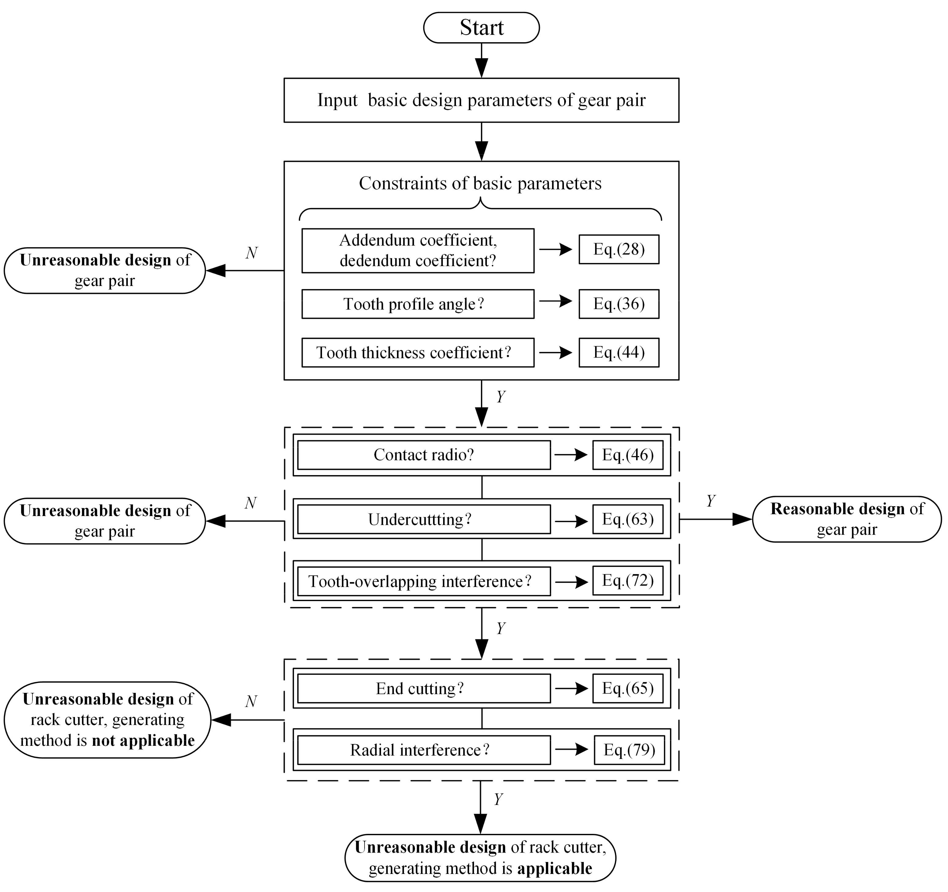
:In order to solve the problem that the design constraints of the conjugated straight-line internal gear pair are unclear, the designing and checking of gear pairs requires repeated trial and error. By analogy with the design of the involute gear pair, the basic design parameters of the conjugated straight-line internal gear pair were clarified. Based on the mathematical model of the gear pair, the constraints on basic design parameters were given according to gear engagement theory and the geometrical relations of the tooth profile. The calculation formula and the constraint of the contact ratio were deduced according to the kinematic relations. Based on Litvin’s undercutting theory, the constraints on avoiding undercutting and end cutting were deduced and their correctness was verified by examples. The judgment method of tooth-overlapping interference and its corresponding numerical calculation flow were presented. The constraint on avoiding radial interference was deduced and analyzed. Based on the above content, the influence laws of design parameters on the design constraints were studied. Last, design examples were given and the effective design flow diagram of the conjugated straight-line internal gear pair was summarized. These research results provide a theoretical basis for the parameter design of conjugated straight-line internal gear pairs, provide guidance to avoid the interference of the gear pair, and promote the design system of the gear pair.
1. Introduction
The conjugated straight-line internal gear pair consists of an external gear with a straight-side profile and its conjugated internal gear ring, whose patent was first proposed by Truninger in 1970 [1]. It has a series of excellent meshing properties, such as smooth operation, small tooth profile curvature, high contact strength, and small relative sliding rate. Through experiment and engineering verification, the gear pair was first applied to the internal gear pump. SAUER-DANFOSS® (Rockford, IL, USA), Bucher® (Klettgau-Griessen, Germany), SUMITOMO® (Tokyo, Japan) all purchased the patent and developed mature products [2]. The advantages of simple structure, small trapped oil volume, small flow pulsation, low noise, and long life give the pump an important position in the hydraulic industry.
Scholars have studied the conjugated straight-line internal gear pair from different angles. In terms of derivation and analysis of the tooth profile equation and meshing characteristics, Wei et al. [3] derived the tooth profile curve equation of the gear pair by using the tooth profile normal reversal method. Song et al. [4] solved the tooth profile curve based on the conjugate tooth profile theory and established the universal mathematical model of gear pair and rack cutter; on this basis, the flow delivery and trapped volume performances of the pump were studied [5], and furthermore, Chen et al. [6] processed the physical prototype and completed the performance test, which verified the correctness of relevant design theories. In terms of gear pair structure and flow field simulation analysis, Chai et al. [7,8,9] built a 3D computational fluid dynamics simulation model of the pump based on Simerics-MP+, a professional pump and valve software, to explore the influence rule of oil properties on pump flow characteristics. Further, Liang et al. [10] studied the time-varying rule of internal flow field characteristics of the pump, including pressure, velocity, trapped oil, and cavitation, etc. At the same time, based on the international standard ISO 10767-1:1996 [11], the flow pulsation test platform of the “secondary source” method was built, and the flow pulsation of the pump was measured and compared with the simulation results to verify the correctness of the test theory and simulation model.
To summarize, the current research on the conjugated straight-line internal gear pair is mostly based on the gear pair model established based on the tooth profile meshing theory, and the research depth is promoted in the aspects of simulation, test, and manufacturing, etc., but there are still the following problems. (1) There is a lack of a systematic summary of the design constraints of the conjugated straight-line internal gear pair. The selection of basic design parameters lacks a theoretical basis; when some design parameters of the gear pair exceed a certain range, the design will experience serious error and failure. Design parameters are mutually constrained rather than independent, and a single change of a parameter may not avoid design errors. It is often necessary to match design parameters reasonably from a global perspective to achieve optimization. (2) The connection between the design and processing of the gear pair is broken; that is, from the perspective of gear transmission, the designed gear pair can operate normally without interference, but from the perspective of gear processing, there may be a variety of interference conditions leading to the failure to obtain the required tooth profile.
Therefore, based on the established mathematical model of the tooth profile of the conjugated straight-line internal gear pair and rack cutter, this paper focuses on the analysis of the design constraints that the gear pair needs to meet in designing and processing, studies the influence rule of gear pair parameters on the constraint conditions, and grasps the design method of the gear pair.
2. Mathematical Model of the Tooth Profile of Gear Pair and Rack Cutter
The parameters shown in Table 1 are defined as the basic design parameters of the conjugated straight-line internal gear pair, whose definition is analogous to that of an involute gear pair [12]. But different from the involute gear pair, the transmission of the conjugated straight-line gear pair is not separable because its profile cannot extend radially indefinitely. When the center distance changes, the tooth profile no longer satisfies the conjugate relation, so the pitch circle of the gear pair coincides with the reference circle. Table 2 shows relevant geometric parameters involved in the mathematical modeling of the gear pair and rack cutter tooth profile.
2.1. Coordinate Systems and Conversions
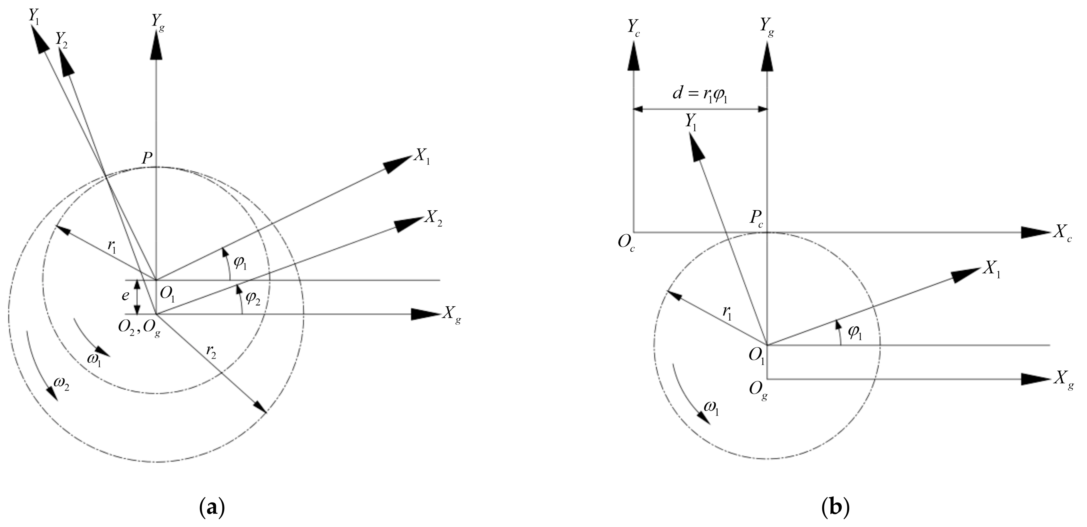
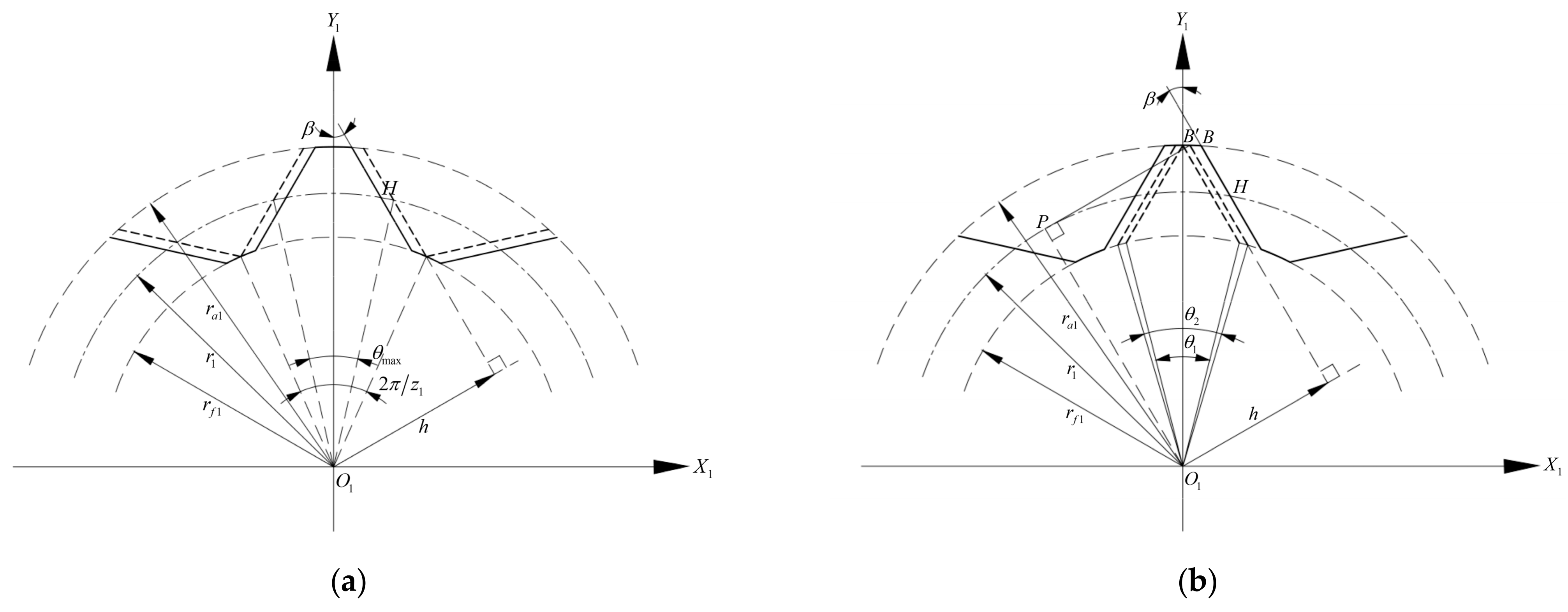
The external gear is machined by rack cutter. The coordinate systems and their movement relations are shown in Figure 1. The fixed coordinate system is fixedly connected with the ground, and the movable coordinate systems , ,
and are fixedly connected with the external gear, internal gear ring, and rack cutter, respectively. The Z-axis of each coordinate system is established in accordance with the right-hand rule. The coordinates and rotate with the external gear and internal gear ring, the coordinate moves parallel with the rack cutter, and the counterclockwise direction is defined as the positive direction of rotation. At this time, the axis and coincide with the rotation axis of the external gear and internal gear ring, respectively, and the pitch circles of the external gear and internal gear ring are tangent to point ; the axis coincides with the pitch line of the rack cutter and is tangent to the pitch circle of the internal gear ring at point . At the initial position, the coordinates and coincide.
Figure 1a,b describes the movement relations between the external gear and internal gear ring, and between the rack cutter and external gear during the meshing process, respectively. Suppose that the external gear and internal gear ring rotate counterclockwise around axis and at the angular velocities and , respectively, for a period of time, and the rotation angles are and . According to the definition of transmission ratio, the transmission ratio of coordinates and can be expressed as follows:
When the rotation angle of coordinate is , the translational displacement of coordinate is . According to the meshing principle, it can be expressed as follows:
The research object is the spur gear pair, so it only needs to model the tooth profile on the plane. Considering the convenience of vector representation and coordinate transformation, the component coordinate of the Z-axis is set as 1. Hence, the transformation matrix from coordinate to can be written as follows:
The transformation matrices from coordinate to and from coordinate to are obtained in the same way:
2.2. Tooth Profile of the External Gear
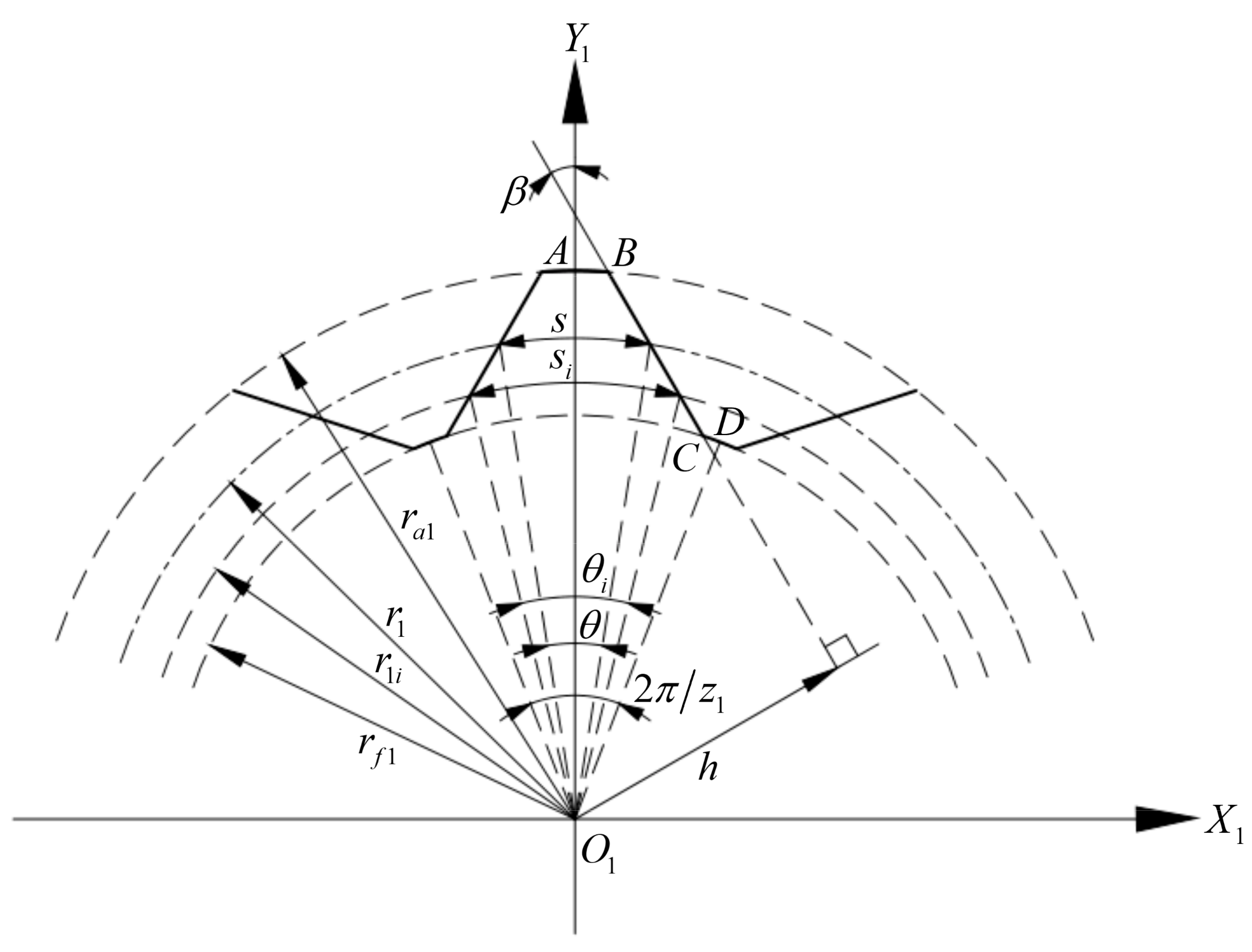
The tooth profile of the external gear in coordinate is shown in Figure 2. The axis coincides with the center line of the gear tooth and the left and right tooth profiles are completely symmetric; therefore, the right tooth profile is modeled mathematically, and then the left can be obtained according to the symmetry relationship. The right tooth profile is composed of three parts: the arc of the addendum circle, the straight-line segment , and the arc of the dedendum circle [1]. Among them, point is located on the axis and point is located on the symmetric center line of the tooth groove of the adjacent gear teeth. Then the mathematical model of the right tooth profile can be expressed by Equations (6)–(8) [4]:
where is the coordinate of the external gear tooth profile in the coordinate , and and are the slope and intercept of straight-line segment , respectively; , , and are the x-coordinate of points , , and , respectively. According to the geometric relationship, it can be obtained as follows:
Then the position vector of the right tooth profile of the external gear can be expressed as follows:
2.3. Tooth Profile of the Internal Gear Ring and Rack Cutter
According to the conjugate tooth profile meshing theory [13], the solution of the tooth profile of the internal gear ring needs to satisfy both the coordinate transformation relation (15) and the meshing Equation (16):
where is the envelope of the curve family formed by the position vector in the coordinate , namely, the position vector of the tooth profile of the internal gear ring. is the normal vector of the tooth profile of the external gear, and is the relative motion velocity at any meshing point on the tooth profiles of the external gear and internal gear ring. Both are defined in the coordinate . From Equation (16), it can be deduced that the tooth profiles of the external gear and internal gear ring need to meet Equation (17) during the meshing process [4]:
By combining Equations (3), (14), (15), and (17), the mathematical model of the tooth profile of the internal gear ring can be obtained.
Similarly, the solution of the tooth profile of the rack cutter needs to satisfy both Equations (18) and (19):
where is the envelope of the curve family formed by the position vector in the coordinate , namely, the position vector of the tooth profile of the rack cutter. is the relative motion velocity at any meshing point on the tooth profiles of the external gear and rack cutter, which is defined in the coordinate . From Equation (19), it can be deduced that the tooth profiles of the external gear and rack cutter need to meet Equation (20) during the meshing process [4]:
By combining Equations (4), (14), (18), and (19), the mathematical model of the tooth profile of the internal ring can be obtained.
3. Design Constraints Analysis of the Gear Pair
3.1. Basic Parameters
Basic design parameters are the basis of modeling the tooth profile of the gear pair and its cutting tool. Unreasonable parameters will directly lead to the failure of design. Therefore, based on the meshing principle and the geometrical relations of the tooth profile, the constraint ranges of basic design parameters were derived.
3.1.1. Addendum Coefficient, Dedendum Coefficient
As shown in Figure 3, in the coordinate , the motion trajectories of the addendum and dedendum of the external gear are circles centered on , with radius and , respectively, and the motion trajectories of the addendum and dedendum of the internal gear ring are circles centered on , with radius and , respectively.
In the transmission process of the gear pair, it is necessary to ensure that there is no interference collision between the addendum of the external gear and the dedendum of the internal gear ring or between the dedendum of the external gear and the addendum of the internal gear ring. The following relationships must be satisfied:
Substituting the relationships between the design parameters in Table 2 into Equation (21), the following can be obtained:
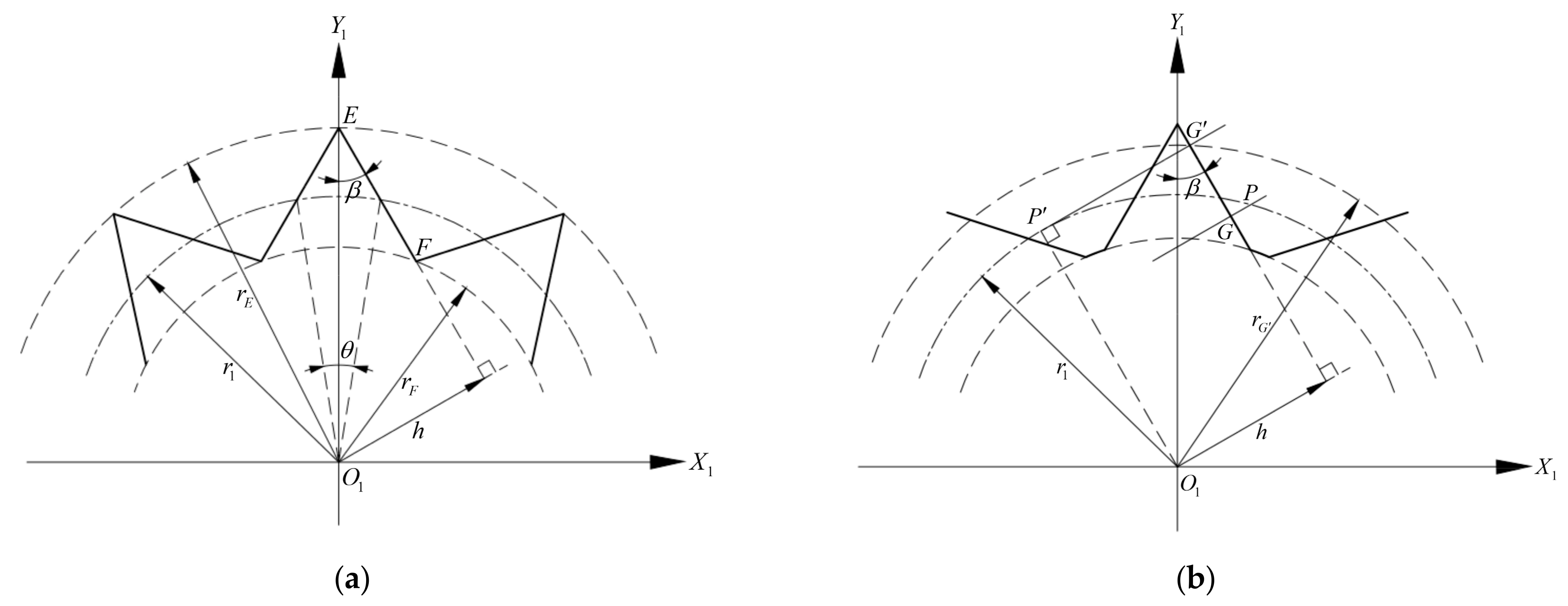
As shown in Figure 4a, tooth profiles on both sides of a single external gear tooth must have an intersection E, and linear tooth profiles of two adjacent gear teeth must have an intersection F. If the tooth profiles exceed this limit position, the design will fail. According to the geometric relationship, the radius of the circle corresponding to the intersection can be written:
where is the vertical distance between the center of the external gear and the linear tooth profile on one side, which can be expressed as follows:
As shown in Figure 4b, there is a meshing boundary point on the linear tooth profile of the external gear. According to the meshing principle, the intersection between the normal line of any meshing point G on the tooth profile and the pitch circle is the pitch point . As the external gear rotates counterclockwise around center point , the meshing point moves to the addendum of the tooth along the tooth profile, and the node moves to the left along the pitch circle. When the normal line of the tooth profile and the pitch circle are tangent to the point , the meshing point is the meshing boundary point. There is no conjugate tooth profile on the linear tooth profile whose radius is larger than the radius of the circle where the point is located. According to the geometric relationship, the circular radius of the point is as follows:
Therefore, it is necessary to avoid the tooth profile of the external gear beyond the intersection and meshing boundary point when designing. In summary, the addendum circle and dedendum circle of the gear pair tooth should meet the following constraints:
Furthermore, the limit range of the addendum coefficient and dedendum coefficient of the gear pair can be given according to Equation (27):
3.1.2. Tooth Profile Angle
Tooth profile angle refers to the included angle between the linear tooth profile and the symmetrical center line of the external gear, which directly determines the shape of the linear tooth profile and is an important parameter affecting the meshing characteristics of the gear pair.
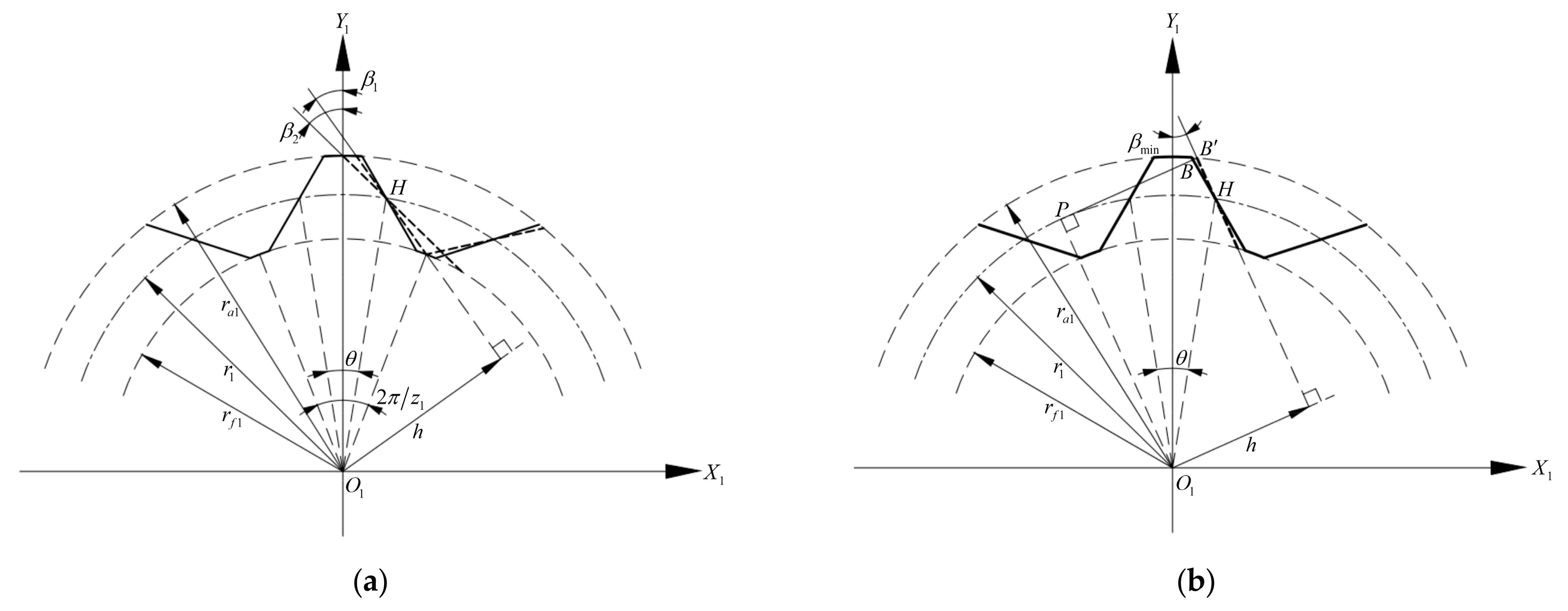
As shown in Figure 5a, the intersection of the linear tooth profile and the reference circle of the external gear is fixed. With the increase of tooth profile angle , the corresponding tooth profiles of the addendum circle and dedendum circle of the external gear decrease. When the tooth profile angle reaches , the dedendum circle will disappear. According to the geometric relationship, the following can be obtained:
The following can be calculated from Equation (29):
When the tooth angle reaches , the addendum circle will disappear. According to the geometric relationship, the following can be calculated
The following can be calculated from Equation (31):
The size of and is determined by specific design parameters. The disappearance of the addendum circle or dedendum circle will lead to the design failure of the external gear. Therefore, the maximum tooth profile angle should be selected as the smaller value of and , namely:
As shown in Figure 5b, it is assumed that the meshing point of the gear pair is at the vertex of the linear tooth profile. As the tooth profile angle decreases, the point moves to the right along the addendum circle, and the normal line through point intersects the pitch circle at the pitch point . According to the meshing principle, when segment is tangent to the pitch circle, the tooth profile angle reaches the minimum value . With the further reduction of the tooth profile angle, the tooth profile at the addendum of the tooth will exceed the meshing boundary point without the conjugate tooth profile. According to the geometric relationship, the following can be obtained:
The following can be calculated from Equation (34):
In summary, the tooth shape angle of the external gear should meet the following constraints:
3.1.3. Tooth Thickness Coefficient of the Reference Circle
As shown in Figure 2, in order to determine the shape of the linear tooth profile of the external gear, two parameters must be determined; the tooth profile angle and the vertical distance can be selected. However, the vertical distance has no intuitive geometric meaning in the actual design; the tooth thickness coefficient of the reference circle is taken as the basic design parameter, and its geometric meaning is the ratio between the tooth thickness and pitch of the reference circle. The larger the coefficient, the larger the central angle corresponding to the tooth thickness of the reference circle, and the greater the bending strength of the tooth.
As shown in Figure 6a, with the increase of the tooth thickness coefficient , the intersection gradually moves to the right, and the corresponding tooth profile of the dedendum circle gradually decreases. When the tooth thickness coefficient reaches , the central angle corresponding to the tooth thickness reaches , and the dedendum circle will disappear. According to the geometric relationship, the following can be obtained:
Substituting the relationship between the design parameters in Table 2 into Equation (37), the following can be calculated:
As shown in Figure 6b, with the decrease of the tooth thickness coefficient , the intersection gradually moves to the left, and the corresponding tooth profile of the addendum circle gradually decreases. When the tooth thickness coefficient reaches , the central angle corresponding to the tooth thickness reaches , and the addendum circle will disappear. According to the geometric relationship, the following can be obtained:
Similarly, the following can be calculated from Equation (39):
It is assumed that the meshing point is at the vertex of the linear tooth profile. The normal line through point intersects the pitch circle at the pitch point . According to the meshing principle, when segment is tangent to the pitch circle, the tooth thickness coefficient reaches and the central angle corresponding to the tooth thickness reaches . With the further reduction of the tooth thickness coefficient, the tooth profile at the addendum of the tooth will exceed the meshing boundary point without the conjugate tooth profile. According to the geometric relationship, the following can be obtained:
The following can be calculated from Equation (41):
The size of and is determined by specific design parameters. The disappearance of the addendum circle or absence of the conjugate tooth profile will lead to design failure. Therefore, the minimum tooth thickness coefficient should be selected as the bigger value of and , namely:
In summary, the tooth thickness coefficient of the reference circle should meet the following constraints:
3.2. Contact Ratio
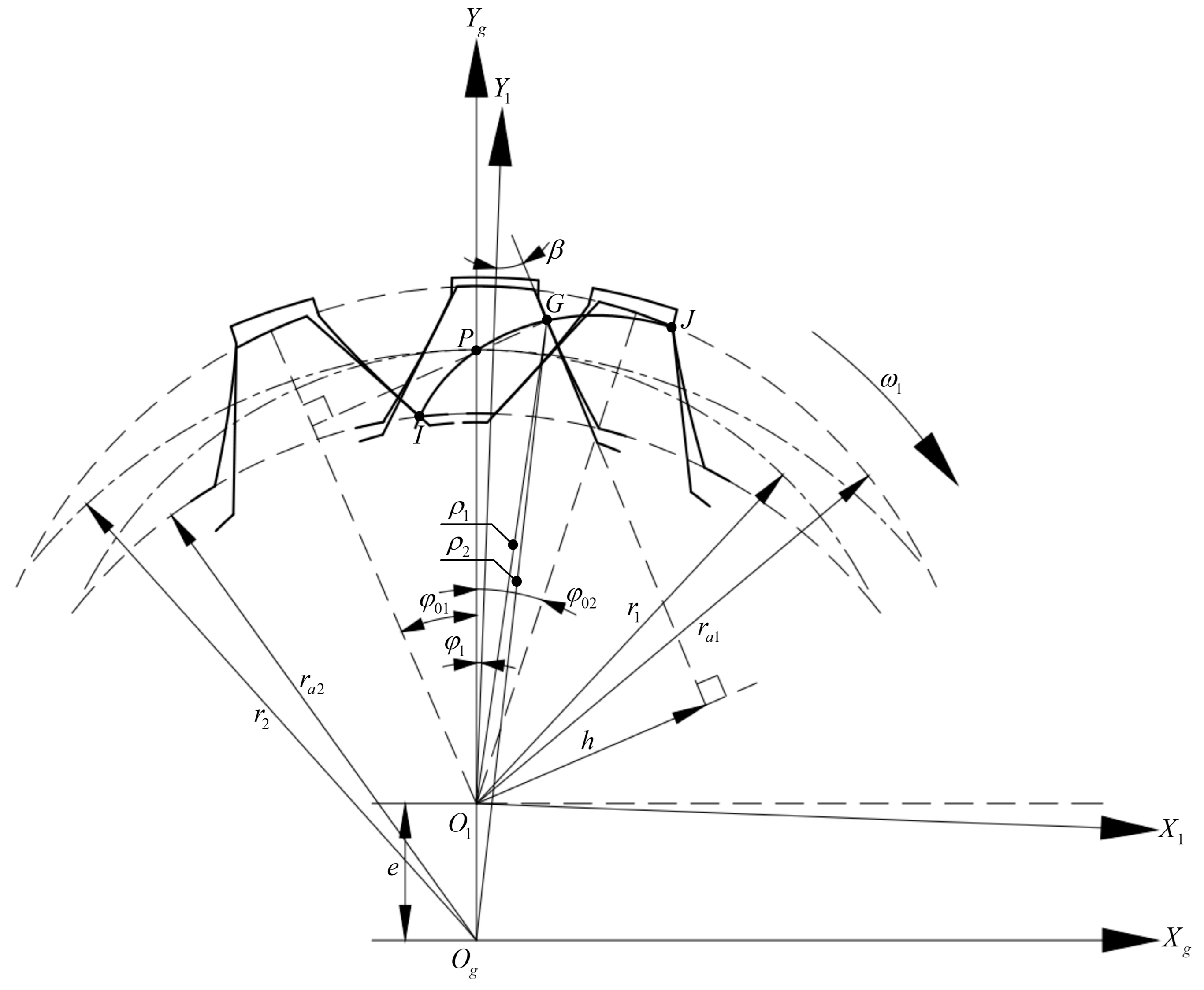
Meshing line refers to the trajectory of the meshing points of a pair of conjugate tooth profiles in a fixed coordinate system [13]. The coordinates of the meshing points in the movable coordinate are converted to the fixed coordinate , then the meshing line equation of the gear pair can be obtained, and the change relation is as follows:
where is the position vector of the meshing line in the coordinate .
Similar to the solution method of conjugate tooth profiles, the solution of must also satisfy the meshing Equation (17) of the gear pair. Taking the design parameters of the gear pair in Table 3 as an example, the meshing line solved by combining Equations (17) and (45) is shown in Figure 7. Its shape is similar to a parabolic curve, different from the linear meshing line of the involute gear pair, so their meshing characteristics are quite different.
In order to ensure the continuity and smoothness of gear transmission, gear pairs must meet the restrictive conditions of the contact ratio . In Figure 7, assuming that the gear pair rotates clockwise and the direction is positive, the curve is the actual meshing line of a pair of gear teeth during the meshing. The point is the intersection between the meshing line and the addendum circle of the internal gear ring, and is the initial meshing point. The point is the intersection between the meshing line and the addendum circle of the external gear, and is the final meshing point. When a pair of gear teeth enter and exit meshing, the corresponding angles of the external gear are and , respectively, so the angle at which the external gear rotates is as the meshing point moves from the point to point , and then the contact ratio of the conjugated straight-line internal gear pair and the constraints it meets are as follows:
In coordinate , the following can be obtained from the geometric relationship in Figure 7:
where and are the distances from the meshing point to the center and of the external gear and internal gear ring, respectively.
When the gear teeth enter meshing, there is a relation: ; when the gear teeth exit meshing, there is a relation: . Substitute the above relations into Equations (47) and (48) to solve, and the expressions of and can be obtained:
Substituting Equations (49) and (50) into Equation (46), the calculation formula and constraint on the contact ratio of the conjugated straight-line internal gear pair can be obtained.
3.3. Interference
Unreasonable design parameters will lead to the interference of the gear pair in the process of meshing transmission and generating manufacture, which will affect the normal operation of the gear pair. Existing research on the interference of internal gear pairs is mostly focused on the involute tooth profile [13,14,15]. Due to the different tooth profiles, the involute verification formula is difficult to apply to the interference check of the conjugated straight-line internal gear pair. Therefore, it is necessary to rederive the formula based on the meshing characteristics, and discuss the interference and the constraints of non-interference.
3.3.1. Undercutting and End Cutting
Undercutting refers to the phenomenon that part of the tooth profile at the dedendum of the machined gear is cut off by the cutting tool during generating manufacture [12]. Undercutting will weaken the bending strength of the tooth dedendum, reduce the contact ratio, and destroy the smoothness of gear transmission. Therefore, it is of great significance to study the undercutting limit conditions of the conjugated straight-line internal gear pair to avoid the undercutting interference of the tooth profile and improve the transmission life of the gear pair.
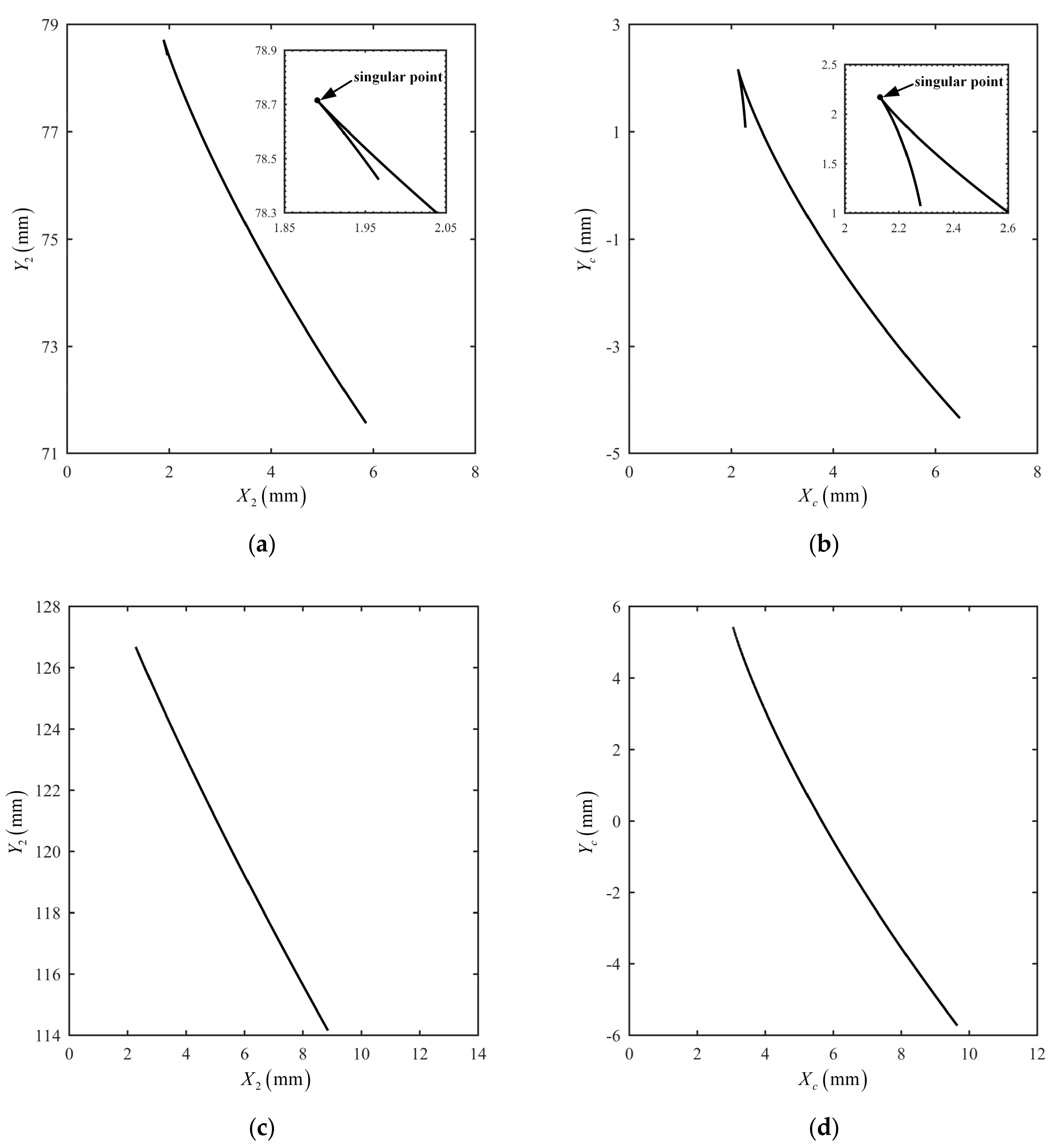
In order to determine the limiting conditions for the non-occurrence of undercutting, refer to the undercutting theory proposed by Litvin [13]: it is assumed that the tooth profile is a tool profile used to process the conjugate tooth profile . If singular points appear in the tooth profile , undercutting will occur in processing, and the singular points should meet the following mathematical conditions:
where is the position vector of the meshing point on the conjugate tooth profile and is the relative motion velocity of the meshing point on the conjugate tooth profile along the tooth profile.
Since the conversion relationship between the position vector of the linear tooth profile of the external gear and the conjugate tooth profile of the internal gear ring is relatively complex, it is not convenient to solve the singular points directly by taking the derivative of the position vectors, so it can be solved according to the relative motion relationship between conjugate tooth profiles. Then the mathematical model of the singular points on the tooth profile can be expressed as follows [16,17,18]:
where is the relative motion velocity of the meshing point of tooth profile along the tooth profile; is the relative motion velocity at the meshing point of the conjugate tooth profiles, namely, the motion velocity of the meshing point on tooth profile relative to tooth profile ; and is the relative motion velocity of the meshing point of tooth profile along the tooth profile. The above velocity vectors are defined in the same coordinate system.
Assuming that the linear tooth profile of the external gear is the tool profile used to process the conjugate tooth profile of the internal gear ring, then, in the coordinate , combining the tooth profile expression and the relative velocity expression, the vectors and in Equation (52) are written in the form of components:
Substituting Equations (53) and (54) into Equation (52), the following can be obtained:
The meshing equation should be satisfied when the linear tooth profile of the external gear is processed to form the conjugate tooth profile of the internal gear ring. Substituting Equation (7) into Equation (17), the following can be obtained:
The following can be obtained by taking the full derivative of Equation (56) with respect to time t:
The angular velocity of the external gear is expressed as follows:
Substituting Equation (58) into Equation (57), a linear equation system with a single unknown can be obtained by combining Equations (55) and (57). The specific form is as follows:
According to matrix theory, in order for the Equation (59) to have a definite non-zero solution, the rank of its augmented matrix and coefficient matrix must be equal to each other and equal to 1, namely:
Then there is the following:
Combined with Equation (56), Equations (7), (54), and (56) are substituted into Equation (61). The position parameters and of the singular point on the conjugate tooth profile of the internal gear ring satisfy the following functional relations:
where .
According to Equation (62), given a set of basic design parameters, the boundary point on the linear tooth profile forming the singular point on the conjugate tooth profile can be determined, whose corresponding x-coordinate is . Taking the right tooth profile of the external gear as an example, it can be seen from Figure 2 that if the boundary point is outside the tool profile of the external gear, that is, the constraint of Equation (63) can be met, the undercutting in the conjugate tooth profile of the internal gear ring can be avoided during the forming process of the linear tooth profile of the external gear.
Similar to undercutting, end cutting refers to the phenomenon that part of the tooth profile at the addendum of the machined gear is cut off by the cutting tool, which will lead to an incomplete tooth profile and will damage the transmission of the gear pair.
Based on the principle of gear generating manufacture, the tooth profile of the rack cutter and the linear tooth profile are conjugate tooth profiles in the process of forming the linear tooth profile of the external gear by rack cutter. Therefore, the generating process can also be regarded as the inverse process of forming the tooth profile of the rack cutter by the linear tooth profile. If the latter experiences undercutting in the forming process, the former is bound to experience end cutting in the forming process. Thus, the problem of end cutting in the process of forming the linear tooth profile can be transformed into the problem of undercutting in the process of forming the tooth profile of the rack cutter.
Therefore, Equation (51) is directly used to carry out the undercutting analysis in the process of forming the tooth profile of the rack cutter by the linear tooth profile of the external gear, so as to determine the constraint that no end cutting occurs in the process of forming the linear tooth profile by rack cutter. The idea and method of derivation are similar to that of undercutting, so it is not repeated here. The position parameters and of the singular point on the tooth profile of the rack cutter can be obtained by solving the following functional relations:
where ,
.
According to Equation (64), given a set of basic design parameters, the boundary point on the linear tooth profile forming the singular point on the tooth profile of the rack cutter can be determined, whose corresponding x-coordinate is . Taking the right tooth profile of the external gear as an example, combined with Figure 2, it can be seen that if the boundary point is outside the external gear’s tool profile, that is, the constraint of Equation (65) can be met, the undercutting in the tooth profile of the rack cutter can be avoided, that is, the end cutting in the linear tooth profile of the external gear during the forming process.
Notably, the generating method uses the principle that the conjugate tooth profiles meshing with each other are mutually enveloping lines. At this time, the processed conjugate tooth profile of the internal gear ring is determined by the tooth profile of the external gear, and the addendum coefficient of the internal gear ring , the dedendum coefficient . If there are boundary points on the linear tooth profile of the external gear, undercutting will inevitably occur in the generating process. Thus, undercutting is the constraint that must be considered in gear pairs processed by the generating manufacture. If the forming method or other processing methods are adopted, although undercutting will not occur in the machining process, if singular points appear on the conjugate tooth profile of the internal gear ring, a complete and smooth conjugate tooth profile curve cannot be obtained, resulting in the designed gear pair being unable to engage in transmission normally. Therefore, in the design and machining of conjugated straight-line internal gear pairs, it is necessary to take the occurrence of undercutting as a necessary constraint. The design process and end cutting of the rack cutter’s profile can be understood in the same way.
To summarize, in order to avoid undercutting and end cutting in the design and machining of the conjugated straight-line internal gear pair, the constraints of Equations (63) and (65) should be satisfied by reasonably matching the basic design parameters of the gear pair.
The four sets of design parameters in Table 4 are taken as examples of undercutting and end cutting. MATLAB® programming is used to calculate the x-coordinates and corresponding to the boundary points of undercutting and end cutting on the linear tooth profile of the external gear, respectively, by using Equations (62) and (64). Then, it is determined whether undercutting and end cutting will occur in the generating manufacture according to the constraints of Equations (63) and (65). The detailed calculations and analysis results are shown in Table 5.
Taking case 2 and case 4 as examples, Figure 8 shows the conjugate tooth profiles of the internal gear ring and rack cutter, and Figure 9 shows the envelope forming process of tooth profiles in the generating manufacture. Since singular points exist on the conjugate tooth profiles corresponding to case 2, and the specific positions are marked out in Figure 8, undercutting and end cutting will occur. At this time, part of the conjugate tooth profile above the singular point at the dedendum of the internal gear ring is cut by the linear tooth profile of the external gear; the linear tooth profile at the addendum of the external gear is cut by the small part of the tooth profile below the singular point at the addendum of the rack cutter; the specific positions are circled by the red outlines in Figure 9. Conjugate tooth profiles corresponding to case 4 have no singular points, so undercutting and end cutting will not occur. The above analysis results verify the correctness of the undercutting and end cutting theory of the conjugated straight-line internal gear pair derived in this paper; in addition, this research idea and method can also be applied to the undercutting determination of other kinds of conjugate tooth profiles in plane.
3.3.2. Tooth-Overlapping Interference
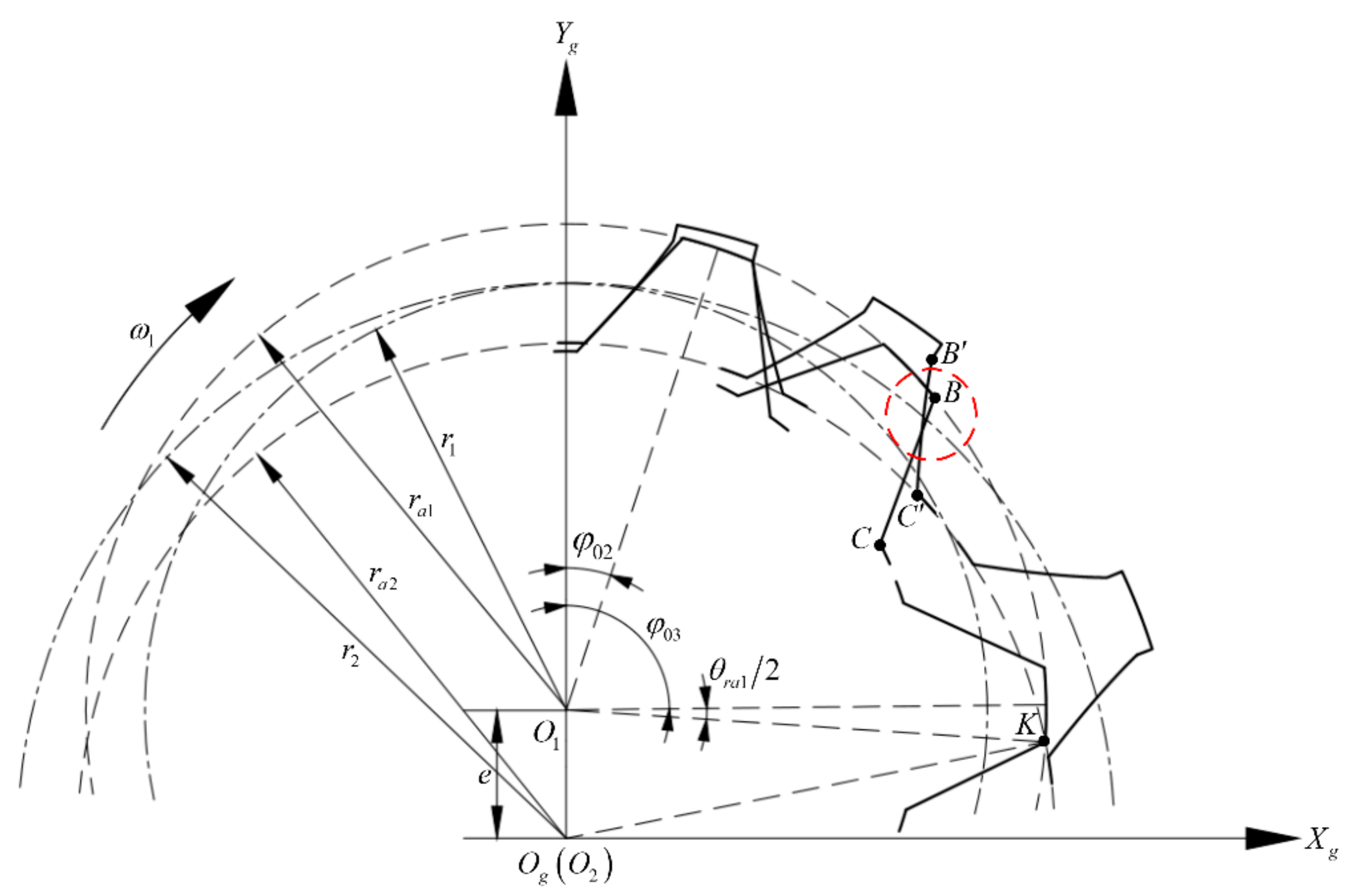
In the transmission of internal gear pairs, the meshing profiles may overlap with each other after they are out of meshing, which is called tooth-overlapping interference. The existence of tooth-overlapping interference will lead to a failed operation, and the gear pairs cannot be installed correctly. Therefore, in the design stage of the gear pair, the check of tooth-overlapping interference must be carried out to avoid the interference.
As shown in Figure 10, in the coordinate Sg, assuming that the gear pair rotates clockwise, the right tooth profile of the external gear and its corresponding conjugate profile are taken as an example. At the initial moment, the axis and coincide, the corresponding angle of the external gear when a pair of conjugate tooth profiles exit meshing is according to Equation (50), and the point is the intersection of the addendum circles of the external gear and internal gear ring. When the linear tooth profile rotates through the point, the two tooth profiles will completely separate, and the tooth-overlapping interference will no longer occur; the corresponding angle of the external gear is at this time. Therefore, the range of the external gear angle corresponding to the check of tooth-overlapping interference is as follows:
According to the geometric relationship in Figure 2, the expression of tooth thickness and its corresponding central angle on any circle of external gear can be deduced:
Substituting the relation into Equation (67), the center angle of the tooth thickness of the external gear addendum circle is as follows:
According to the geometric relationship in Figure 10, the following can be obtained:
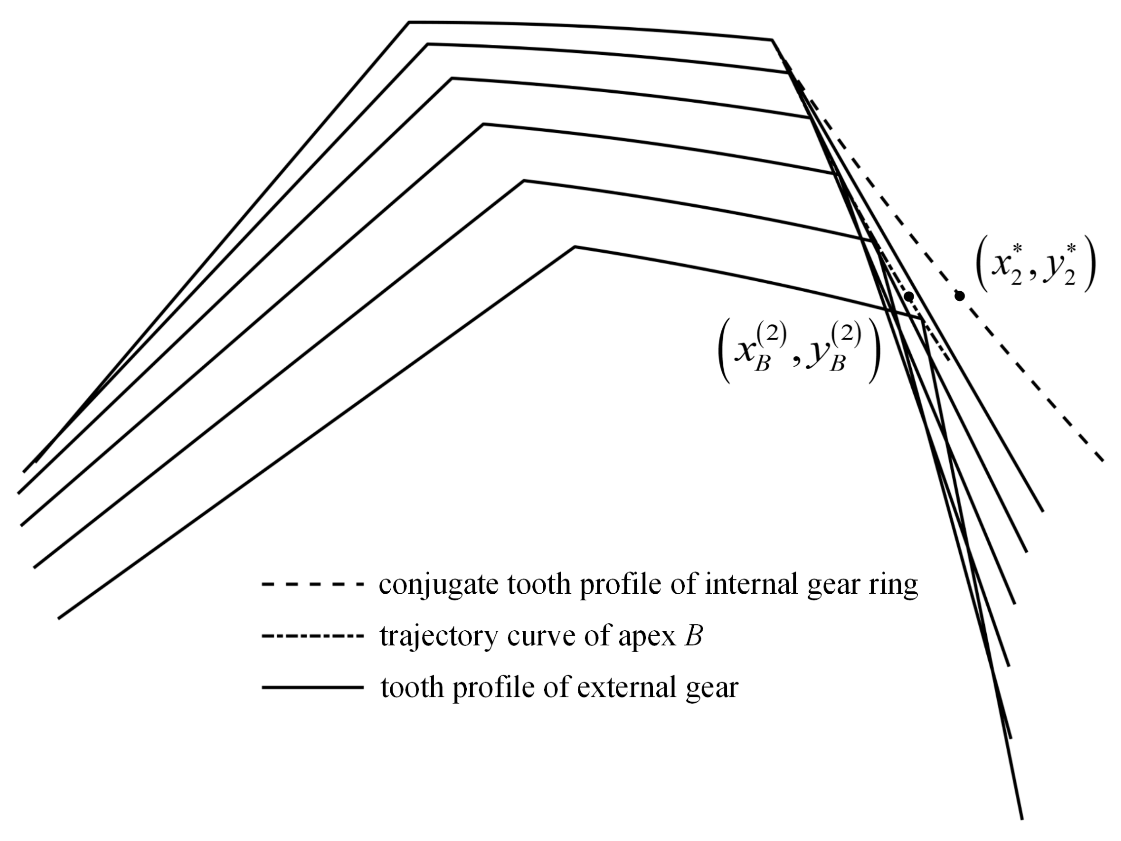
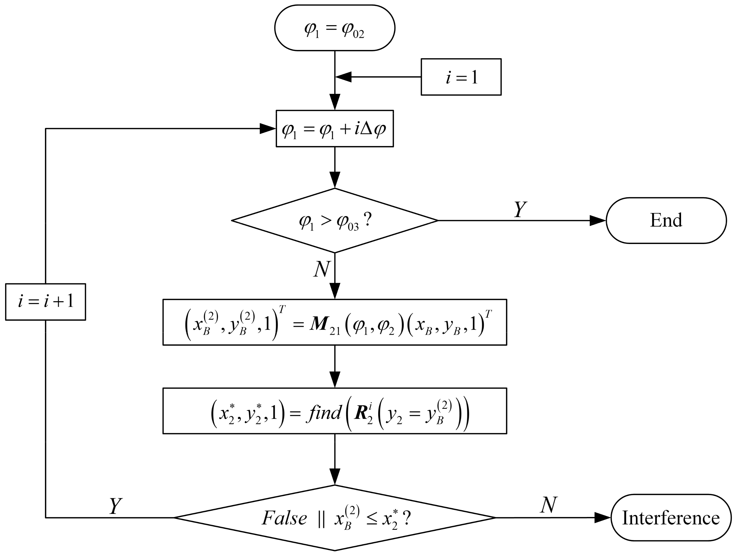
In Figure 10, the position of interference is circled by the red outline. If tooth-overlapping interference occurs, the apex of the linear tooth profile will definitely be embedded into the conjugate tooth profile of the internal gear ring, and the apex is located on the right side of the conjugate tooth profile. Therefore, the following judgment method is intended to be adopted to the check of tooth-overlapping interference: in the coordinate , the motion trajectory of the apex will form a curve, and the coordinates of curve can be obtained by the coordinate transformation of Equation (71). If the curve intersects with the conjugate profile curve of the internal gear ring, tooth-overlapping interference will inevitably occur; otherwise, it will not occur.
As shown in Figure 11, this method transforms the complex problem of tooth-overlapping interference into the problem of judging whether there is an intersection between the conjugate tooth profile of the internal gear ring and the trajectory curve of the apex of the linear tooth profile in the coordinate . Furthermore, the checking ranges of the angle and conjugate profile curve are discretized, and the numerical calculation method is used to make the above method easy to be programmed. The specific calculation flow is shown in Figure 12; when the angle of the external gear is , find the coordinate of the point on the position vector of the internal gear ring’s profile, which is equal to the y-coordinate of point . If no corresponding point can be found or the relation exists, it indicates that the point is located on the left side of the conjugate profile curve under this angle, and thus no tooth-overlapping interference occurs. If the relation exists, it indicates that point is located on the right side of the conjugate profile curve, and then the tooth-overlapping interference occurs. Complete the check of tooth-overlapping interference within the whole range of the angle . If no tooth-overlapping interference occurs within the whole range, the tooth-overlapping interference of the gear pair will not occur; otherwise, it will. Therefore, the constraint of no tooth-overlapping interference of the conjugated straight-line internal gear pair can be written in the following form:
where is the decision function of tooth-overlapping interference.
3.3.3. Radial Interference
Radial interference means the following in the assembly process of the internal gear pair, the external gear can only be assembled into the internal gear ring along the axial direction, but the external gear cannot be installed to the meshing position along the radial direction from the center of the internal gear ring. At this point, if the external gear is used as a slotting cutter for the radial cutting and generating motion to process the internal gear ring by the generating method, there will be an end cutting in the internal gear ring. Therefore, the radial interference is a constraint that must be satisfied when the gear pair is machined by the generating method, but not when the gear pair is designed.
In the coordinate , the conjugate tooth profiles on the right are still taken as an example. The initial meshing position is located at pitch point . At this time, the included angles between the radius of the tooth apexes and of the gear pair and the axis are and , respectively. The following can be obtained from the geometric relationship in Figure 13:
where and d2 are the distance from the apexes and of the gear pair to the axis , respectively. and are the included angles between the radius on the pitch circles and the radius of the apexes and at the tooth profile on the same side, respectively.
As can be seen from Figure 2, the coordinate of the intersection of the reference circle of the external gear and the straight-line segment is ; combined with Equations (7) and (11), the length of the straight-line segment is as follows:
In Δ, the following is obtained according to the law of cosines:
Since the conjugate tooth profile of the internal gear ring is an irregular curve, the point coordinates on the tooth profile cannot be directly solved through geometric relationships. Based on the mathematical model of the tooth profile of the internal gear ring in Section 2.3, MATLAB® programming is used to solve the coordinates of the intersections and of the conjugate tooth profile of the internal gear ring with its reference circle and addendum circle, and then the length of the straight-line segment is as follows:
In Δ, the following is obtained according to the law of cosines:
In Figure 13, when , the radial interference of the gear pair will occur at the angle ; on the contrary, when , the radial interference of the gear pair will not occur. Thus, the constraint that there is no radial interference of the conjugated straight-line internal gear pair can be written in the following form:
where is the decision function of radial interference.
4. Influences of the Design Parameters on Design Constraints
A set of design parameters used in the gear pump in Table 3 is taken as an example. The influence laws of design parameters on the design constraints are studied by controlling a single variable, which provides a theoretical basis for parameter design and interference avoidance of the gear pair. During the discussion, since the necessary and sufficient conditions of the value range of design parameters cannot be directly given, the value range of the parameters is determined by the necessary conditions in Section 3.1. Based on the above theory, the value range of the addendum coefficient of the external gear is 0–0.7286, the value range of the dedendum coefficient of the external gear is 0–0.9003, the value range of the addendum coefficient of the internal gear ring is 0–0.8, and the minimum value of the dedendum coefficient of the internal gear ring is 0.7. The value range of the tooth profile angle is 24.18°–28.64°, and the value range of the tooth thickness coefficient of the reference circle is 0.4548–0.5528. The value range of the parameters will be further restricted after considering the constraints such as the contact ratio and interference.
4.1. Basic Parameters
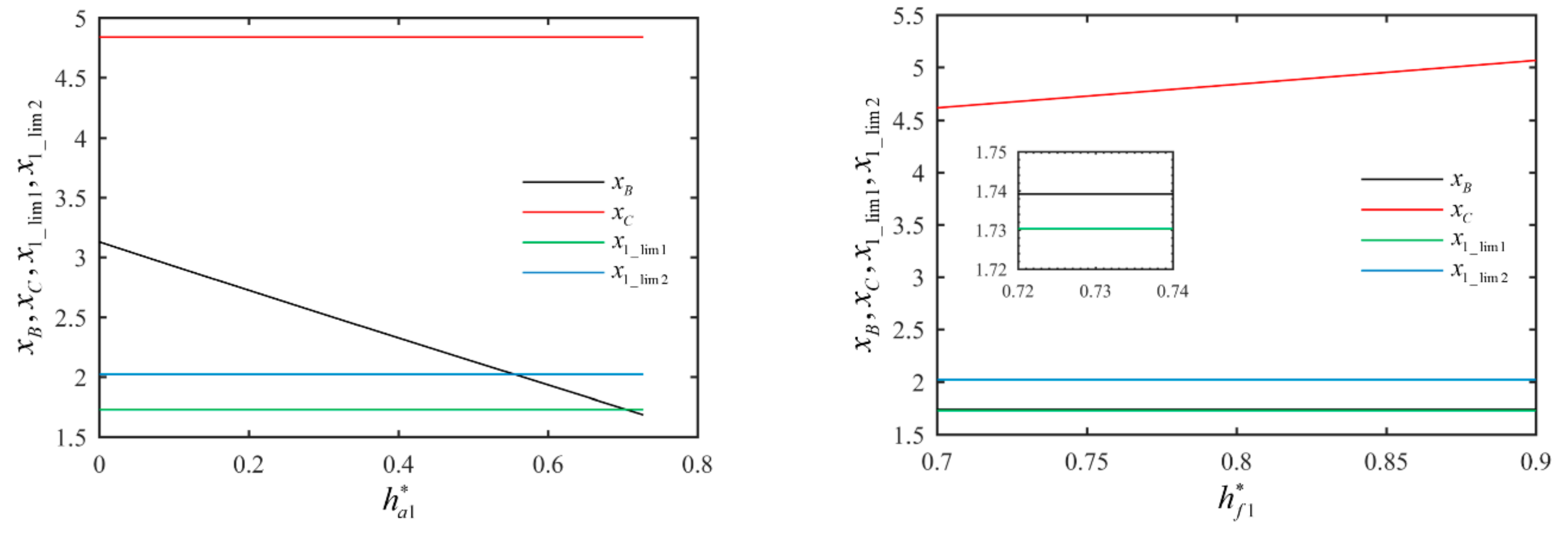
Through the analysis of the derivation process and calculational formulas of the constraints on basic parameters, when the teeth number , is determined, the design parameters , , have no influence on the constraints on tooth profile angle and tooth thickness coefficient , while the parameters , , , are determined by the design parameters , , , and . The influences of the above parameters on parameters , , , and are shown in Figure 14.
The results show the following:
(1) The maximum tooth profile angle is negatively correlated with the parameters and , but independent of the parameters and ; the minimum tooth profile angle is positively associated with the parameter , whose growth trend is determined by the Equation (35), and negatively correlated with the parameter , but independent of the parameters and .
(2) The maximum tooth thickness coefficient is negatively correlated with the parameters and , but independent of the parameters and ; the minimum tooth thickness coefficient is negatively correlated with the parameter , but independent of the parameters and , and positively correlated with the parameter and there is an obvious “inflection point” in its variation curve, which has been marked out in Figure 14a. Combined with the content in Section 3.1.3, at the first stage of the “inflection point,” the minimum value ks_min is determined by Equation (40), and at the later stage of the ”inflection point,” the minimum value is determined by Equation (42).
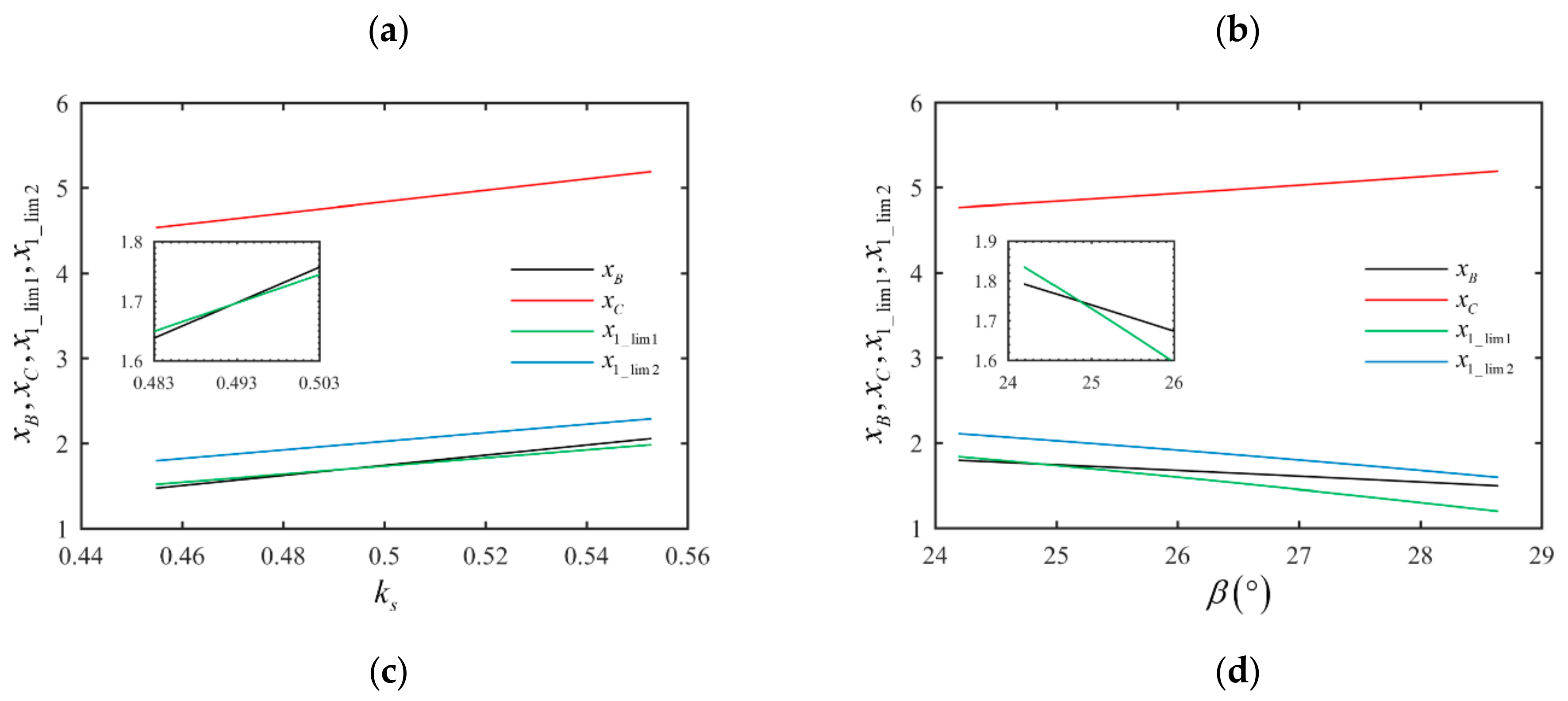
4.2. Contact Ratio
Through the analysis of the derivation process and calculational formulas of the contact ratio of the gear pair, when the teeth number , is determined, the design parameters , , have no influence on the contact ratio, while the contact ratio is determined by the design parameters , , , and . The influences of the above parameters on the contact ratio are shown in Figure 15.
The results show the following:
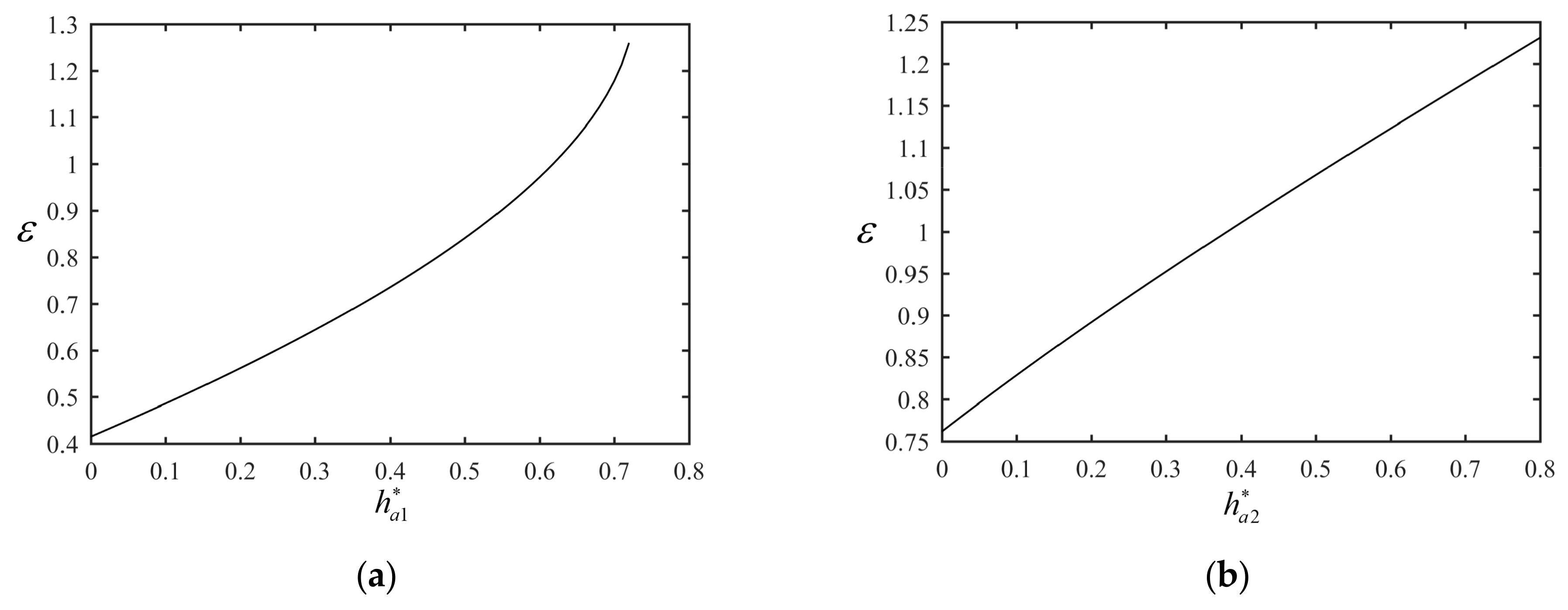
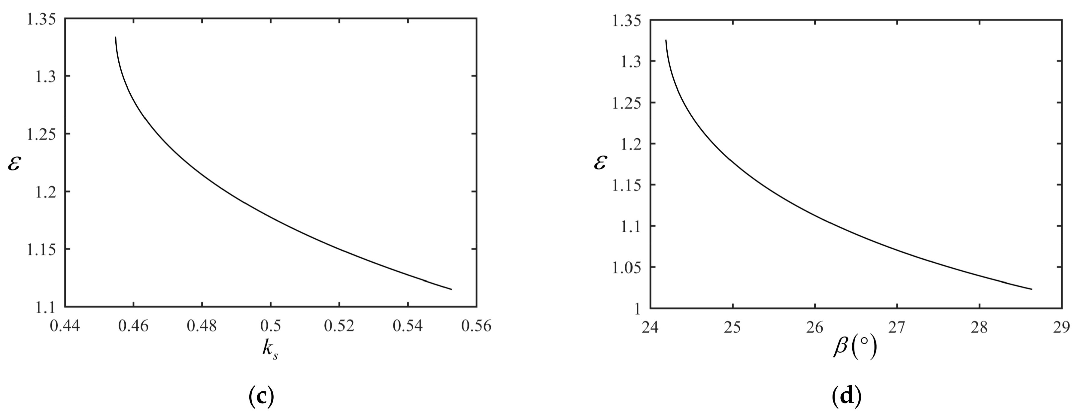
(1) In Figure 15, the contact ratio is positively associated with the parameters and , and negatively associated with the parameters and ; the growth trend is determined by the Equation (46).
(2) In Figure 15a, as the addendum coefficient gradually increases to the upper limit, the growth rate of the contact ratio gradually increases. On the one hand, it indicates that the meshing time of the tooth profile near the addendum is longer than that of the other parts of the tooth profile, and a small increase in the tooth height here can achieve a better effect of increasing the contact degree; but on the other hand, a larger contact ratio will lead to a serious oil trapping phenomenon, resulting in vibration and noise. Therefore, the value of the addendum coefficient cannot be too close to the upper limit. Similarly, as can be seen from Figure 15c,d, when the parameters and gradually decrease to the lower limit, the growth rate of the contact ratio gradually increases; the value of tooth thickness coefficient and tooth profile angle should not become too close to the lower limit in the actual design.
(3) In Figure 15a,b, when the constraint of the contact ratio is satisfied, the value ranges of the addendum coefficients and need to be further restricted. Based on the content in Section 3.2, it can be obtained by programming that the value range of the addendum coefficient of the external gear is 0.6179–0.7286, and the addendum coefficient of the internal gear ring is 0.3816–0.8 when the constraint of the contact ratio is satisfied.
4.3. Interference
4.3.1. Undercutting and End Cutting
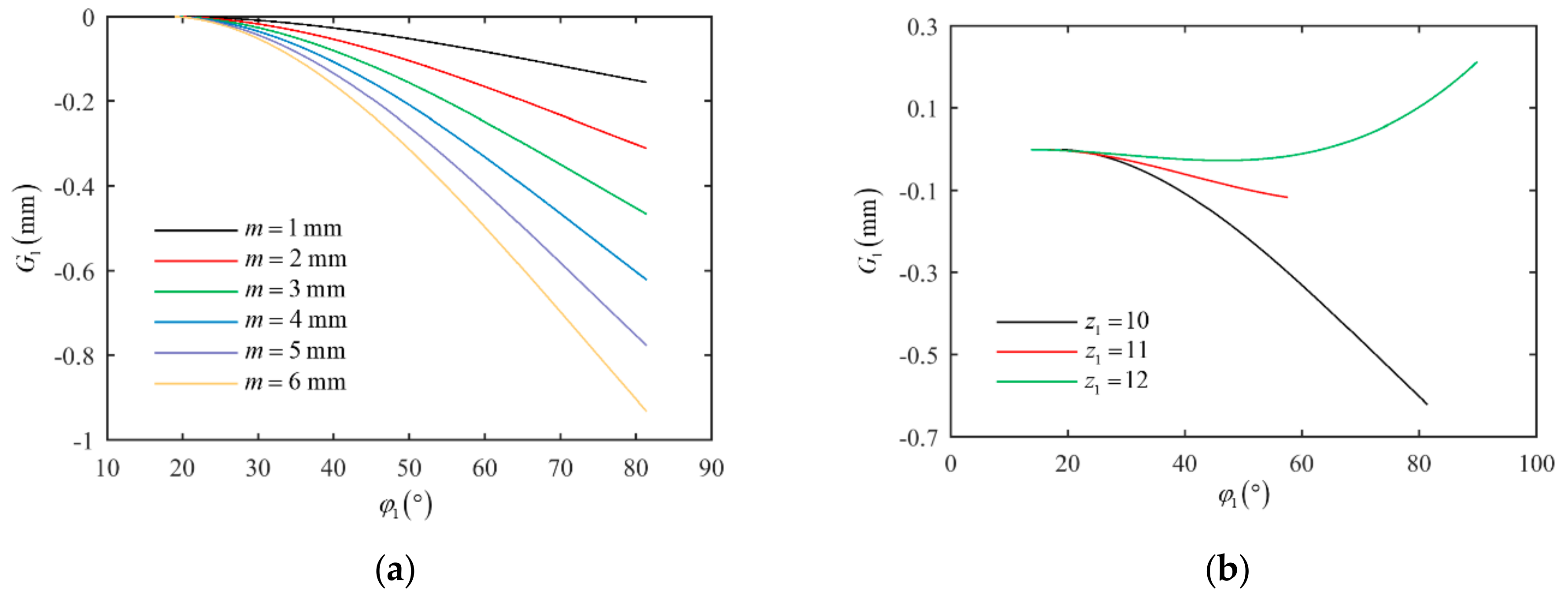
Through the analysis of the derivation process and calculational formulas of the constraints of undercutting and end cutting, whether undercutting and end cutting occur depends on the relationship of size between the x-coordinate of boundary points , and the x-coordinates of endpoints , on the tooth profile of the external gear. When the teeth number , is determined, the design parameters , , have no influence on the constraints, while the constraints are determined by the design parameters , , , and . The influences of the above parameters on parameters , , , are shown in Figure 16.
The results show the following:
(1) In Figure 16, the boundary points of the linear tooth profile are close to the apex B. Combined with the constraints (63) and (65), the occurrence of undercutting and end cutting can be determined by comparing the relationship of size between the parameters , , and .
(2) In Figure 16a, as the addendum coefficient gradually increases, the x-coordinate of decreases linearly, and the x-coordinates and of the boundary points remain constant, indicating that the locations of singular points of the conjugate tooth profiles are not affected by the parameter ; parameters , , and change from satisfying to not satisfying the constraints (63) and (65), that is, from no occurrence to the occurrence of undercutting and end cutting. Similarly, in Figure 16b, the parameters , , and remain constant with the increase of dedendum coefficient , indicating that the change of parameter has no effect on undercutting and end cutting, and undercutting will not occur, but end cutting will occur according to the constraints. In Figure 16c, the parameters , , and all increase linearly with the increase of tooth thickness coefficient , and parameters and change from not satisfying to satisfying the constraint (63), that is, from the occurrence to no occurrence of undercutting, while parameters and do not satisfy the constraint (65) all the time; that is, end cutting always occurs. In Figure 16d, the parameters , , and all decrease linearly with the increase of tooth profile angle , and parameters and change from not satisfying to satisfying the constraint (63), that is, from the occurrence to no occurrence of undercutting, while parameters and do not satisfy the constraint (65) all the time; that is, end cutting always occurs.
(3) The value ranges need to be further restricted if the constraints of undercutting and end cutting are satisfied. Combined with the content in Section 3.3.1, the coordinates of intersections in Figure 16 can be solved by programming, and it can be obtained that the value range of the addendum coefficient is 0–0.7047, the tooth thickness coefficient is 0.4925–0.5528, and the tooth profile angle is 24.87°–27.64° when the constraint of undercutting is satisfied. The value range of the addendum coefficient is 0–0.5555 when the constraint of end cutting is satisfied.
To summarize, undercutting and end cutting can be avoided by reasonably matching the design parameters of the gear pair to meet the constraints (63) and (65). Specifically, undercutting can be avoided by reducing the addendum coefficient of the external gear, increasing the tooth thickness coefficient of the reference circle and the tooth profile angle ; end cutting can be avoided by reducing the addendum coefficient of the external gear.
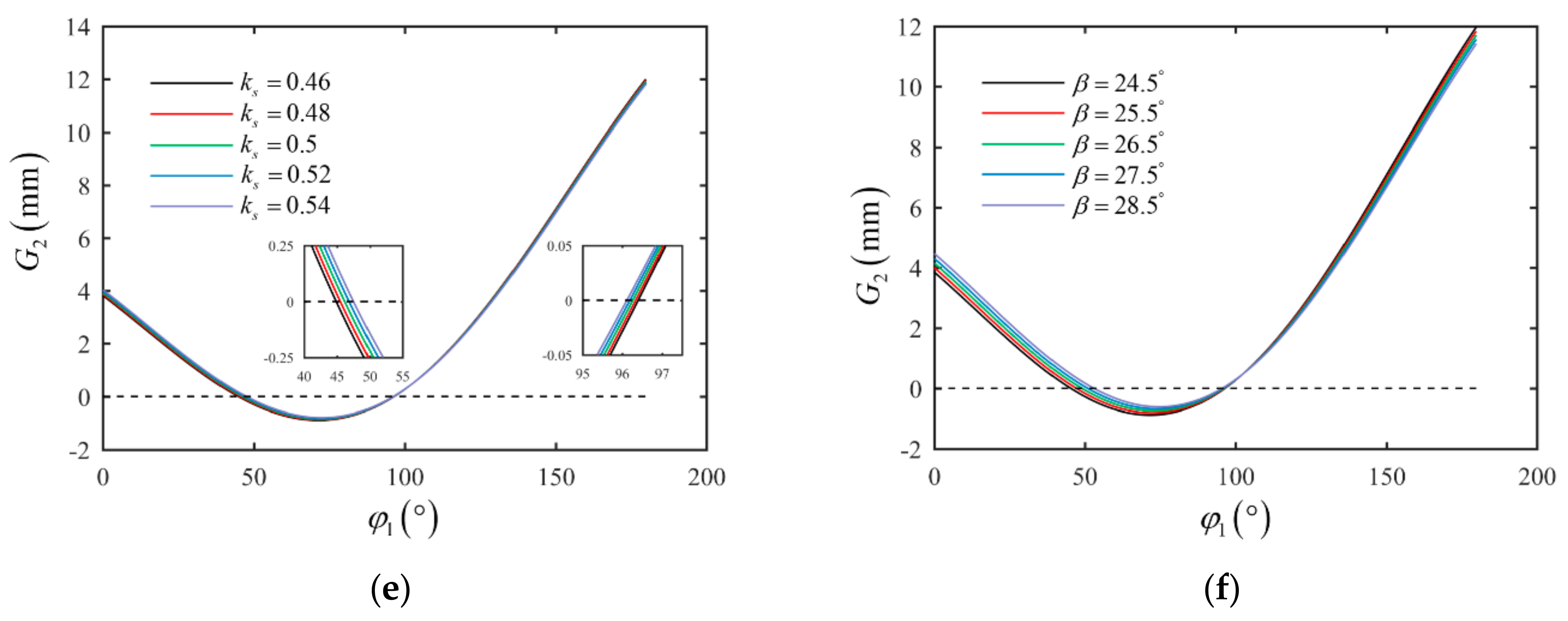
4.3.2. Tooth-Overlapping Interference
Through the analysis of the derivation process and calculation formulas of the constraint of tooth-overlapping interference, the decision function of tooth-overlapping interference varies with external gear angle . The smaller the value of is, the smaller the transverse distance between the apex and the conjugate tooth profile of the internal gear ring is, and the value range of angle is determined by Equation (66). It is worth noting that, with the change of design parameters, there may be an unreasonable value range of angle solved or no intersection of the addendum circles of the external gear and internal gear ring. If the former occurs, it indicates that the design parameters are unreasonable and there is no need to discuss it; if the latter occurs, it is verified that the value range of the angle can be set as 0–90° to complete the tooth-overlapping interference check under these design parameters. In addition, the function is not affected by the design parameters , , and , but is related to the parameters , , , , , . The influences of the above parameters on the function are shown in Figure 17.
The results show the following:
(1) In Figure 17a, when the module increases from 1 mm to 6 mm, the value range of angle does not change, indicating that the module has no influence on the checking range of interference. Meanwhile, the relation is always valid in the checking range of angle , satisfying the constraint (72), indicating that no tooth-overlapping interference occurs. Since the size of the gear pair is proportional to the module, combined with the calculation results, it can be obtained that the transverse distance between the apex and the conjugate tooth profile is the same as the increase proportion of the module at the same angle , indicating that the change of module will affect the value of the function , but will not affect the check result of the tooth-overlapping interference; that is, the interference cannot be avoided by adjusting the module.
(2) In Figure 17b, when the teeth number of the external gear is 10 and 11, the relation is valid within the whole range of the angle , satisfying the constraint (72), and no tooth-overlapping interference occurs. When the teeth number increases to 12, the relation exists and the tooth-overlapping interference occurs. This indicates that the larger the teeth number , the more likely that the interference will occur. Similarly, it can be seen from Figure 17c that the larger the teeth number , the less likely that the interference will occur.
(3) As can be seen from Figure 17d, when the addendum coefficient increases from 0.1 to 0.7, the relation is valid in the whole checking range of the angle , satisfying the constraint (72), and no tooth-overlapping interference occurs. The larger the addendum coefficient , the smaller the transverse distance between the apex and the conjugate tooth profile will be, and the more likely that the interference will occur. Similarly, it can be seen from Figure 17e,f that no tooth-overlapping interference occurs when the tooth thickness coefficient or the tooth profile angle increases, and the larger the parameters or , the less likely that the interference will occur.
To summarize, the tooth-overlapping interference can be avoided by reasonably matching the design parameters of the gear pair to meet the constraint (72). Specifically, it can be satisfied by increasing the difference of teeth number, the tooth thickness coefficient of the reference circle, and the tooth profile angle , reducing the addendum coefficients of the external gear.
4.3.3. Radial Interference
Through the analysis of the derivation process and calculational formulas of the constraint of radial interference, the decision function of radial interference varies with the external gear angle , and the value range of the angle can be set as 0–180° according to the symmetric relationship. In addition, the function is not affected by the design parameters and , but is related to the parameters , , , , , . The influences of the above parameters on the function are shown in Figure 18.
The results show the following:
(1) In Figure 18a, when the teeth number of the external gear increases from 10 to 12, the relation exists and the corresponding value range of angle becomes larger, indicating that radial interference occurs, and the larger the parameter , the more likely that radial interference will occur. Similarly, as shown in Figure 18b, the corresponding value range of angle becomes smaller to the relation as the teeth number of the internal gear ring increases from 11 to 14, indicating that the larger the parameter, the less likely that radial interference will occur. When the teeth number increases to 15, the relation is valid within the whole value range of the angle satisfying the constraint (79), and radial interference no longer occurs.
(2) As can be seen from Figure 18c, when the addendum coefficient is less than 0.3, the relation is valid in the whole value range of the angle , satisfying the constraint (79), and no radial interference occurs. With the further increase of the parameter to 0.7, the relation occurs and the corresponding value range of the angle becomes larger, indicating that radial interference occurs, and the larger the parameter , the more likely that radial interference will occur. As shown in Figure 18d, when the addendum coefficient increases from 0.1 to 0.7, the relation exists all the time and the corresponding value range of angle becomes larger, indicating that radial interference occurs, and the larger the parameters , the more likely that radial interference will occur. As shown in Figure 18e,f, the corresponding value range of angle becomes smaller to the relation when the tooth profile angle increases from 24.5° to 28.5° or the tooth thickness coefficient increases from 0.46 to 0.54, indicating that the larger the parameters and , the less likely that radial interference will occur.
To sum up, radial interference can be avoided by reasonably matching the design parameters of the gear pair to meet the constraint (79). Specifically, it can be satisfied by increasing the difference of teeth number, the tooth thickness coefficient of the reference circle, and the tooth profile angle , reducing the addendum coefficients and of the gear pair.
5. Design Examples
Taking the design parameters in Table 3 as an example, the values of parameters satisfy the constraints in Section 3.1, and the contact ratio , satisfying the constraint Equation (46). According to the theory in Section 3.3.1, the design parameters satisfy the constraint Equation (63) of undercutting, but do not satisfy the constraint Equation (65) of end cutting. As shown in Figure 17 and Figure 18, the relation is always valid in the checking range of angle , satisfying the constraint Equation (72), and the relation exists in the value range of angle , not satisfying the constraint Equation (79). The above calculated results show that the values of the basic design parameters all satisfy the constraints; the designed gear pair meets the constraint of contact ratio, and undercutting and tooth-overlapping interference will not occur, but end cutting and radial interference will occur. If the generating method is adopted to machine the gear pair, it is necessary to modify the design of the rack cutter for the external gear and the slotting cutter for the internal gear ring, or to reasonably adjust the design parameters, so as to avoid undercutting and radial interference in the generating process. If the forming method or other processing methods are adopted, the designed gear pair has met the requirement of normal transmission, and axial assembly can be adopted.
According to the mathematical model in Section 2, the profiles of the gear pair and rack cutter can be determined if a set of basic design parameters are known. In fact, the working profiles in the transmission process of the gear pair are the linear tooth profile of the external gear and the corresponding conjugate tooth profile of the internal gear ring; the tooth profiles of the addendum and dedendum circles, which can be designed according to the parameter relation in Table 2, do not need to satisfy the conjugate relation, namely, Equation (16). However, the gear pair with normal transmission can be designed only if the constraints in Section 3 are satisfied. Similarly, the rack cutter can be designed in the same way. In summary, according to the design flow diagram shown in Figure 19, reasonable conjugated straight-line internal gear pairs and rack cutters for external gears can be designed.
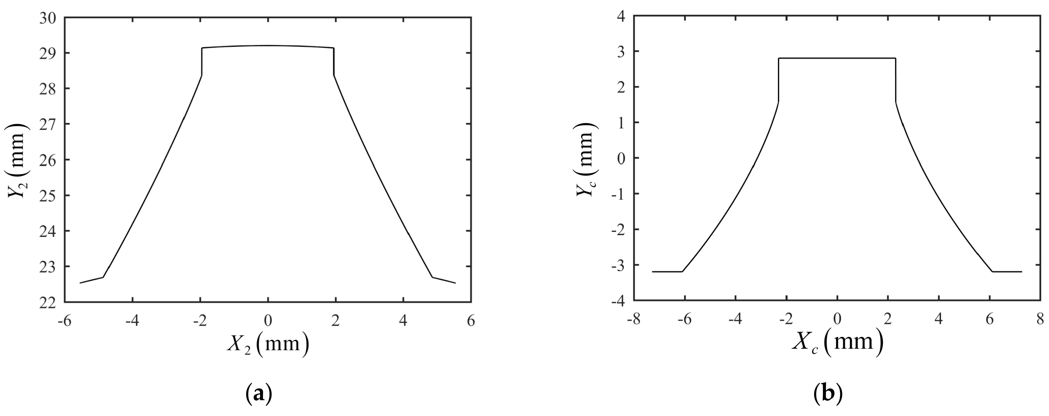
Furthermore, MATLAB® programming is used to solve the mathematical model of tooth profiles. For the internal gear ring, the three segments of the tooth profile have the following relations: the conjugate tooth profile does not intersect with the tooth profile of the dedendum circle, and intersects with the tooth profile of the addendum circle. Here, in order to facilitate the solid modeling of the gear pair, the following correction methods are used for reference [4,6]: the transition curve of the tooth profile of the dedendum circle and the conjugate tooth profile is simplified into a straight line; the intersection of the tooth profile of the addendum circle and the conjugate tooth profile is found; and the tooth profiles exceeding the intersection are discarded. The method is also adopted for the tooth profiles of the rack cutter and the small segment of the tooth profile below the singular point of the conjugate tooth profile is abandoned. The modified tooth profiles of the internal gear ring and rack cutter are shown in Figure 20.
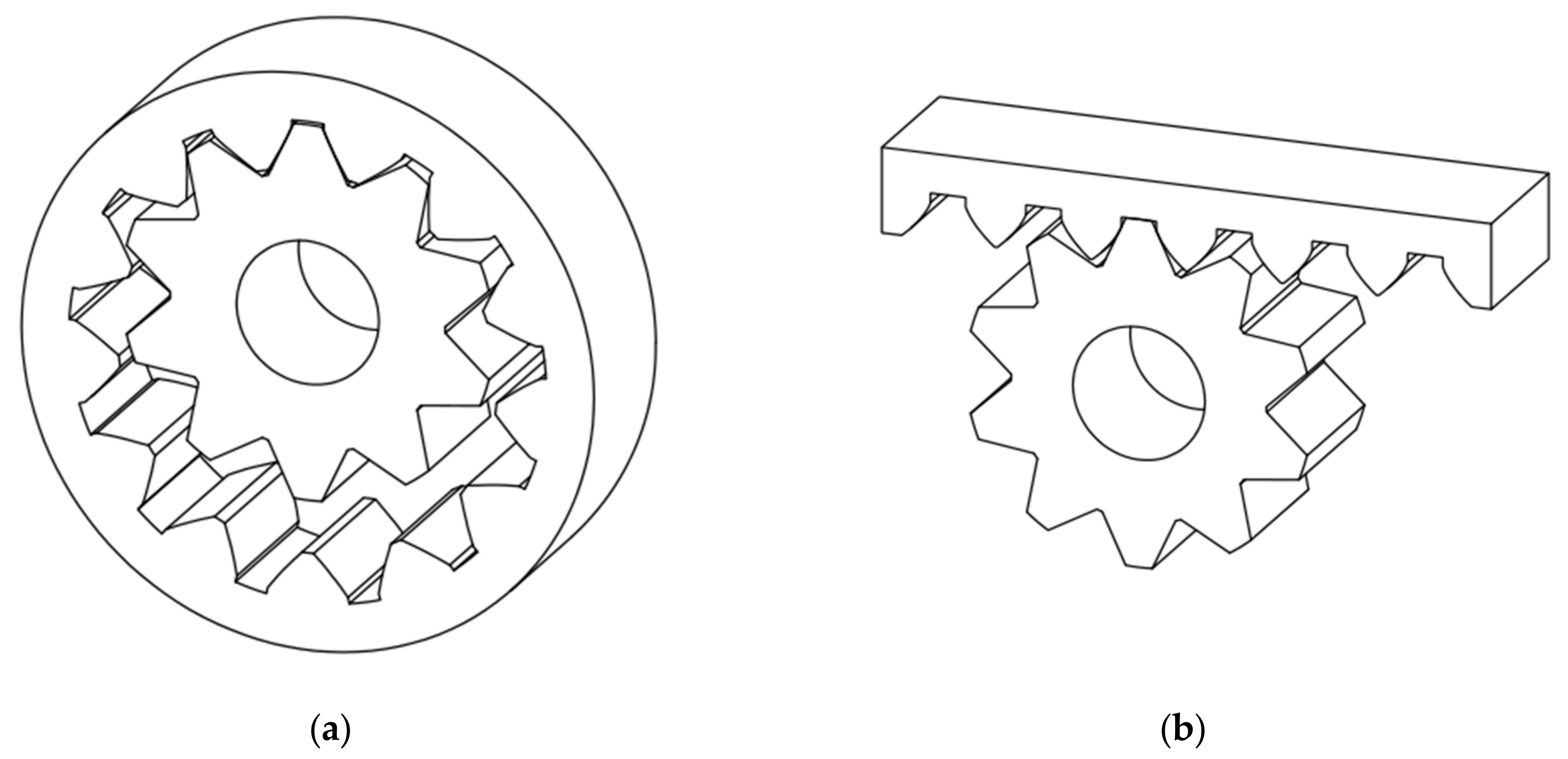
The coordinates of the tooth profile solved by MATLAB® are imported into the design software SoildWorks®, the complete tooth curves are generated after mirroring and arraying, and then the 3D geometric models of the gear pair are obtained by stretching; the models assembled according to the meshing relationship are shown in Figure 21. The model of the rack cutter is built in the same way. The accuracy of the models is related to the step size of parameter in the equations of the external gear’s tooth profile. The smaller the step size, the more coordinates on the tooth curves, and the higher the accuracy of the models.
6. Conclusions
This article has carried out a detailed investigation into the design constraints of the conjugated straight-line internal gear pair for the first time, based on the mathematical model of the gear pair. The constraints of the gear pair in the designing and machining process, such as design parameters, contact ratio, and interference, were deduced, and the influence of design parameters on the design constraints were analyzed, such as number of teeth, module, tooth profile angle, tooth thickness coefficient, addendum coefficient, etc. The design flow diagram of the gear pair and rack cutter was summarized, which should be helpful in the design and manufacture of gear pairs. The following conclusions can be drawn from this study:
- (1)
- The basic design parameters of the conjugated straight-line internal gear pair are clarified; the tooth profile of the gear pair is determined by nine parameters of , , , , , , , , and . Based on the mathematical model of the gear pair, the constraints of basic design parameters are given according to gear engagement theory and the geometrical relations of the tooth profile.
- (2)
- The calculation formula and the constraint of the contact ratio are deduced according to the kinematic relations. Based on Litvin’s undercutting theory, the constraints on avoiding undercutting and end cutting are deduced and their correctness is verified by examples. The judgment method of tooth-overlapping interference and its corresponding numerical calculation flow are presented. The constraint on avoiding radial interference is deduced and analyzed.
- (3)
- The influences of design parameters on the design constraints are studied; design faults and interference can be avoided by reasonably matching the design parameters to meet the corresponding constraints, in the following specific ways: ① undercutting can be avoided by reducing the addendum coefficient of the external gear, increasing the tooth thickness coefficient of the reference circle and the tooth profile angle ; ② end cutting can be avoided by reducing the addendum coefficient of the external gear; ③ tooth-overlapping interference can be avoided by increasing the difference of teeth number, the tooth thickness coefficient of the reference circle, and the tooth profile angle , reducing the addendum coefficients of the external gear; ④ radial interference can be avoided by increasing the difference of teeth number, the tooth thickness coefficient of the reference circle, and the tooth profile angle , reducing the addendum coefficients and of the gear pair.
- (4)
- Design examples are given and the effective design flow diagram of the conjugated straight-line internal gear pair is summarized.
Author Contributions
All authors contributed to the study conception. The manuscript has been written by Y.L. All authors have read and agreed to the published version of the manuscript.
Funding
This work is supported by National Natural Science Foundation of China (Funder, Zongbin Chen; Funding number, 52205077).
Institutional Review Board Statement
Not applicable.
Informed Consent Statement
Not applicable.
Data Availability Statement
Not applicable.
Conflicts of Interest
The authors declare no conflict of interest.
References
- Paul, T. GEAR PUMP. 1970. [Google Scholar]
- Zongbin, C.; Lin, H.; Jian, L. Test Study on Output Flow Pulsations of Conjugated Straight-line Internal Gear Pumps. Chin. Mech. Eng. 2021, 32, 1801–1811. [Google Scholar]
- Weifeng, W.; Guangpeng, Z.; Zhenyi, D.; Ning, K. Design method of internal rotary gear pump by parameterized line conjugated tooth profile. Chin. J. Mech. Eng. 2014, 50, 49–55. [Google Scholar]
- Wei, S.; Hua, Z.; Yonggang, Z. Design of the conjugated straight-line internal gear pairs for fluid power gear machines. Proc. Inst. Mech. Eng. Part C J. Mech. Eng. Sci. 2013, 227, 1776–1790. [Google Scholar]
- Wei, S.; Yinglong, C.; Hua, Z. Investigation of fluid delivery and trapped volume performances of Truninger gear pump by a discretization approach. Adv. Mech. Eng. 2016, 8, 1–15. [Google Scholar]
- Zongbin, C.; Lin, H.; Jian, L. Design and analysis of conjugated straight-Line internal gear pairs. Int. J. Precis. Eng. Manuf. 2021, 22, 1425–1440. [Google Scholar] [CrossRef]
- Hongqiang, C.; Guolai, Y.; Guoguo, W.; Guixiang, B.; Wenqi, L. Research on flow characteristics of straight line conjugate internal meshing gear pump. Processes 2020, 8, 269. [Google Scholar] [CrossRef] [Green Version]
- Hongqiang, C.; Guolai, Y.; Xiaoxiong, L.; Dayu, Y. Influence of oil properties on flow characteristics of straight line conjugate internal meshing gear pump. J. Huazhong Univ. Sci. Tech. (Nat. Sci. Ed.) 2022, 50, 19–25. [Google Scholar]
- Hongqiang, C.; Guolai, Y.; Guoguo, W.; Guixiang, B.; Chuanchuan, C. Analysis of straight conjugate internal gear pump through numerical modeling and experimental validation. PLoS ONE 2022, 17, e0270979. [Google Scholar]
- Yundong, L.; Zongbin, C.; Jian, L. Numerical simulation and experimental evaluation of flow ripple characteristics of Truninger pump. Sci. Rep. 2022, 12, 11297. [Google Scholar]
- BS ISO 10767-1:1996; Hydraulic Fluid Power—Determination of Pressure Ripple Levels Generated in Systems and Components—Part 1: Method for Determining Source Flow Ripple and Source Impedance of Pumps. ISO: Geneva, Switzerland, 1996.
- Norton, R.L. Design of Machinery; McGraw-Hill: New York, NY, USA, 2001; Volume 125, p. 650. [Google Scholar]
- Litvin, F.L.; Fuentes, A. Gear Geometry and Applied Theory; Cambridge University Press: Cambridge, UK, 2004. [Google Scholar]
- Colbourne, J.R. Gear-tooth interference. ASME J. Mech. Des. 1983, 105, 298–301. [Google Scholar] [CrossRef]
- Litvin, F.L.; Hsiao, C.L.; Wang, J.C.; Zhou, X. Computerized simulation of generation of internal involute gears and their assembly. ASME J. Mech. Des. 1994, 116, 683–689. [Google Scholar] [CrossRef]
- Chang, S.L.; Tsay, C.B.; Wu, L. Mathematical model and undercutting analysis of elliptical gears generated by rack cutters. Mech. Mach. Theory 1996, 31, 879–890. [Google Scholar] [CrossRef]
- Chang, S.L.; Tsay, C.B. Computerized Tooth Profile Generation and Undercut Analysis of Noncircular Gears Manufactured With Shaper Cutters. ASME J. Mech. Des. 1998, 120, 92–99. [Google Scholar] [CrossRef]
- Litvin, F.L.; Egelja, A.M.; Donno, M.D. Computerized determination of singularities and envelopes to families of contact lines on gear tooth surfaces. Comput. Metho. App. Mech. Eng. 1998, 158, 23–34. [Google Scholar] [CrossRef]
Figure 1.
Movement relations between coordinate systems: (a) external gear and internal gear ring; (b) rack cutter and external gear.
Figure 1.
Movement relations between coordinate systems: (a) external gear and internal gear ring; (b) rack cutter and external gear.

Figure 2.
Tooth profile of the external gear.

Figure 3.
Motion trajectories of the addendum and dedendum.

Figure 4.
Constraints of the addendum circle and dedendum circle of the external gear: (a) intersection; (b) meshing boundary point.
Figure 4.
Constraints of the addendum circle and dedendum circle of the external gear: (a) intersection; (b) meshing boundary point.

Figure 5.
Extreme value of the tooth profile angle: (a) maximum value; (b) minimum value.

Figure 6.
Extreme value of the tooth thickness coefficient of the reference circle: (a) maximum value; (b) minimum value.
Figure 6.
Extreme value of the tooth thickness coefficient of the reference circle: (a) maximum value; (b) minimum value.

Figure 7.
Meshing relationship of the conjugated straight-line internal gear pair.

Figure 8.
Conjugate tooth profiles and their singular points: (a) profile of internal gear ring (case 2); (b) profile of rack cutter (case 2); (c) profile of internal gear ring (case 4); (d) profile of rack cutter (case 4)).
Figure 8.
Conjugate tooth profiles and their singular points: (a) profile of internal gear ring (case 2); (b) profile of rack cutter (case 2); (c) profile of internal gear ring (case 4); (d) profile of rack cutter (case 4)).

Figure 9.
Generating process of the tooth profiles: (a) profile of internal gear ring (case 2); (b) profile of external gear (case 2); (c) profile of internal gear ring (case 4); (d) profile of external gear (case 4). (The specific positions of undercutting and end cutting are circled by the red outlines).

Figure 10.
Analysis of the tooth-overlapping interference. (The specific position of tooth-overlapping interference is circled by the red outline).
Figure 10.
Analysis of the tooth-overlapping interference. (The specific position of tooth-overlapping interference is circled by the red outline).

Figure 11.
Determination principle of tooth-overlapping interference.

Figure 12.
Calculation flow of the check of tooth-overlapping interference.

Figure 13.
Analysis of radial interference.

Figure 14.
Influences of design parameters on parameters , , , : (a) ; (b) ; (c) ; (d) .

Figure 15.
Influences of design parameters on the contact ratio: (a) ; (b) ; (c) ; (d) .


Figure 16.
Influences of design parameters on parameters , , , : (a) ; (b) ; (c) ; (d) .


Figure 17.
Influences of design parameters on the function : (a) ; (b) ; (c) ; (d) ; (e) ; (f) .


Figure 18.
Influences of design parameters on the function G2: (a) ; (b) ; (c) ; (d) ; (e) ; (f) .


Figure 19.
Design flow diagram of the gear pair and rack cutter.

Figure 20.
Tooth profiles: (a) internal gear ring; (b) rack cutter.

Figure 21.
Geometric models: (a) external gear and internal gear ring; (b) rack cutter and external gear.
Figure 21.
Geometric models: (a) external gear and internal gear ring; (b) rack cutter and external gear.


Table 1.
Basic design parameters of the gear pair.
| Name | External Gear | Internal Gear Ring |
|---|---|---|
| Number of teeth | ||
| Module | ||
| Addendum coefficient | ||
| Dedendum coefficient | ||
| Tooth profile angle | - | |
| Tooth thickness coefficient of reference circle | - | |
Where is the tooth thickness of the reference circle and is the pitch of the reference circle.
Table 2.
Geometrical parameters and calculation formulas of the gear pair.
| Name | Calculation Formulas | |
|---|---|---|
| External Gear | Internal Gear Ring | |
| Reference radius | ||
| Center distance | ||
| Addendum | ||
| Dedendum | ||
| Addendum radius | ||
| Dedendum radius | ||
| Addendum clearance coefficient | - | |
| Central angle of tooth thickness of reference circle | - | |
Table 3.
Design parameters of the gear pair.
| 10 | 13 | 25° | 4 mm | 0.7 | 0.8 | 0.7 | 0.8 | 0.5 |
Table 4.
Design parameters for undercutting and end cutting examples.
| Design Parameters | Case 1 | Case 2 | Case 3 | Case 4 |
|---|---|---|---|---|
| 3 | 4 | 5 | 6 | |
| 10 | 17 | 20 | 28 | |
| 13 | 38 | 29 | 40 | |
| 23 | 25 | 26 | 27 | |
| 0.45 | 0.5 | 0.55 | 0.6 | |
| 0.6 | 1 | 1.1 | 1.2 | |
| 1 | 1 | 1 | 0.9 | |
| 1 | 1 | 1 | 0.9 | |
| 0.6 | 1 | 1.1 | 1.2 |
Table 5.
Results of undercutting and end cutting examples.
| Results | Case 1 | Case 2 | Case 3 | Case 4 |
|---|---|---|---|---|
| 1.3076 | 1.2133 | 1.5514 | 1.8951 | |
| 3.5516 | 5.1417 | 6.9233 | 8.5423 | |
| 1.2987 | 1.4085 | 1.3567 | 0.5206 | |
| 1.4699 | 1.6395 | 1.9305 | 1.5278 | |
| Undercutting? | × | √ | × | × |
| End cutting? | √ | √ | √ | × |
Disclaimer/Publisher’s Note: The statements, opinions and data contained in all publications are solely those of the individual author(s) and contributor(s) and not of MDPI and/or the editor(s). MDPI and/or the editor(s) disclaim responsibility for any injury to people or property resulting from any ideas, methods, instructions or products referred to in the content. |
© 2023 by the authors. Licensee MDPI, Basel, Switzerland. This article is an open access article distributed under the terms and conditions of the Creative Commons Attribution (CC BY) license (https://creativecommons.org/licenses/by/4.0/).
Share and Cite
MDPI and ACS Style
Liang, Y.; Chen, Z.; Zhang, Y.; Liao, J. Study on Design Constraints of Conjugated Straight-Line Internal Gear Pair. Machines 2023, 11, 412. https://doi.org/10.3390/machines11030412
AMA Style
Liang Y, Chen Z, Zhang Y, Liao J. Study on Design Constraints of Conjugated Straight-Line Internal Gear Pair. Machines. 2023; 11(3):412. https://doi.org/10.3390/machines11030412
Chicago/Turabian StyleLiang, Yundong, Zongbin Chen, Yantao Zhang, and Jian Liao. 2023. "Study on Design Constraints of Conjugated Straight-Line Internal Gear Pair" Machines 11, no. 3: 412. https://doi.org/10.3390/machines11030412
Note that from the first issue of 2016, this journal uses article numbers instead of page numbers. See further details here.