
Effect of the Stiffness of the Turntable Bearing Joint on the Dynamic Characteristics of the Five-Axis Machine Tool Rotary System

Key Laboratory of Advanced Manufacturing and Intelligent Technology, Ministry of Education, Harbin University of Science and Technology, Harbin 150080, China
*
Author to whom correspondence should be addressed.
Machines 2023, 11(3), 389; https://doi.org/10.3390/machines11030389
Submission received: 13 January 2023
/
Revised: 21 February 2023
/
Accepted: 23 February 2023
/
Published: 16 March 2023
(This article belongs to the Section Advanced Manufacturing)
Abstract
:The positioning accuracy and machining performance of the five-axis machine tool are significantly impacted by the dynamic characteristics of the rotary system of the two-axis rotary table machine. In this study, first, the stiffness of the joint bearing of the rotary table system is calculated, and the effect of bearing clearance and external load on the stiffness is analyzed. Second, considering the stiffness characteristics of the joint, the natural frequency and mode shapes of the turntable system are calculated. Finally, the influence of turntable angle and bearing stiffness on the dynamic characteristics of the turntable system is analyzed. The results show that the natural frequency of the rotary table system does not change obviously with the axial stiffness of the turntable bearing joint, but increases significantly with the increase in the radial stiffness. The first order natural frequency of the turntable decreases with the increase in the swing angle, and the change in the first order natural frequency is 77.43 Hz. The research results provide theoretical basis and guidance for machine tool design and use.
1. Introduction
The static deformation of table surface is influenced by the support stiffness of turntable. The static stiffness of the turntable bearing directly affects dynamic characteristics of the workbench.
Common turntable bearings are double volleyball bearings, three-row cylindrical roller bearings and other four forms. When studying the stiffness of single-row cylindrical roller bearing, scholars discovered that for cylindrical roller bearing, its stiffness is not only affected by the structure and installation process, but also closely related to the actual working conditions (such as speed, lubrication, temperature and external load) [1,2,3,4]. In the existing research of three-row cylindrical roller bearings, the main focus is on the calculation and stress analysis of roller load as well as the analysis of the life and strength of bearings [5,6,7,8,9]. For the effective analysis of cylindrical roller bearings, the actual stress state of rollers needs to be determined. Göncz et al. [5] used the symmetrical three-dimensional finite element model of three-row cylindrical roller bearing to numerically calculate the distribution of internal contact force and determine the stress field in the contact area between roller and raceway. Li and Jiang [6] calculated the internal stress distribution of three-row cylindrical roller bearings by using finite element analysis and a mixed finite element model combining solid and spring elements. Li et al. [7] carried out finite element analysis on the elastic–plastic characteristics of contact between cylindrical roller and raceway, and calculated the contact stress distribution. Wang et al. [8] borrowed a set of nonlinear springs to simulate each roller in this way so as to establish an equivalent finite element model with certain reliability, and obtained load–deformation characteristics. He et al. [9] used the substitution method to replace the solid rollers with the nonlinear springs, and then analyzed the actual load conditions to obtain the maximum contact load between rollers and raceways, and established a local contact CAD model between rollers and raceways. Based on engineering experience and the calculation formula of strain measurement, the stiffness model of three-row cylindrical roller bearings is analyzed in the literature [10,11]. He and Wang [10] analyzed the effect of different bolt types, bolt pre-tightening force, and roller diameter on the structural stiffness and strength of three-row cylindrical roller bearings. Wei et al. [11] calculated the static stiffness matrix of the three-row cylindrical roller table bearings by considering the load distribution of a radial cylindrical roller and its interaction with axial roller load. However, research on the static stiffness of three-row cylindrical roller turntable bearings and its effect on the dynamic characteristics of the turntable is lacking. Therefore, the static deformation and dynamic characteristics of the turntable are very important to the analysis of the machine tool turntable. In order to accurately analyze its characteristics, it is necessary to analyze the stiffness of the turntable bearing in the static state and its impact on the overall dynamic characteristics of the turntable.
In the process of research, modeling the joint surface of the machine tool and identifying the dynamic characteristic parameters are the main focus of the work. Li et al. [12] analyzed the dynamic characteristics of different machining positions of machine tools based on Kriging method. Chen et al. [13] studied the dynamic contact characteristics and dynamic stiffness of single-nut ball screw pairs, and established the dynamic stiffness model of all ball raceway contact pairs. Chen et al. [14] used the classical contact theory to establish the contact stiffness model of ball screw pair and guide pair. Yu et al. [15] used the contact characteristics of linear guide rail to establish the dynamic stiffness model of the system under different load conditions and operating time. Liu et al. [16] analyzed the spindle/tool holder contact stiffness model based on the Majumdar and Bhushan model (MB model) [17]. In recent years, many modifications of the MB model were proposed based on multi-scale fractal contact theory [18,19,20].
However, there is still a lack of research on the static stiffness of three-row cylindrical roller turntable bearings and the dynamic characteristics of the turntable under different machining attitudes. In order to accurately analyze the static deformation and dynamic characteristics of the turntable, it is important to consider the static stiffness of the turntable bearing and the dynamic characteristics of the turntable under the influence of different machining swing angles. In this study, based on the modified Palmgren cylindrical roller elasticity approximation formula, the stiffness of bearing joints is calculated, the effects of bearing clearance and external load on the stiffness are discussed, and the finite element model of the rotary table system is established. Based on this, the theoretical modal analysis of the turntable is carried out, and then the swing angle and bearing stiffness of the turntable are studied, and its influence on the dynamic characteristics of the turntable system is obtained.
2. Basic Structure of Turntable Rotary System
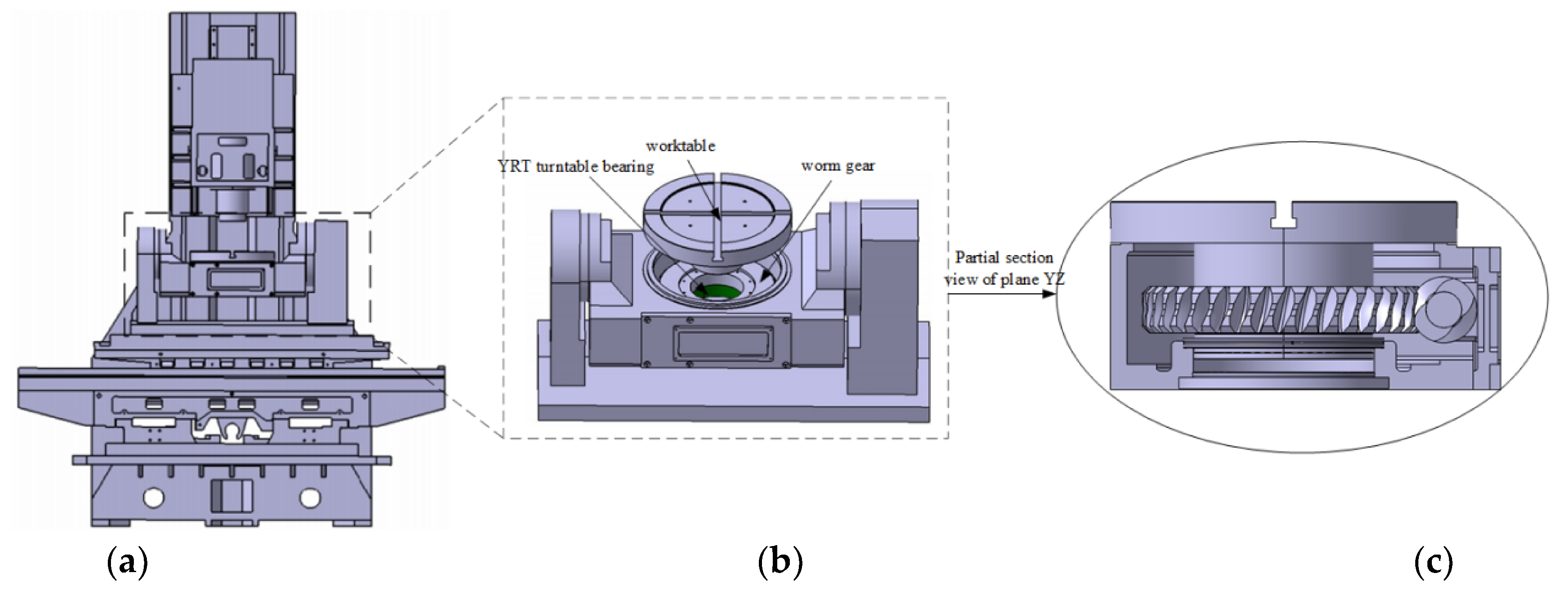
In this study, the AC shaft two-axis rotary table of the five-axis machine tool is adopted as the research object. Its specific structure is shown in Figure 1. The main mechanical joint parts of the worktable include turntable bearing joint part, worm gear and worm joint part, fixed joint part and swing arm bearing joint part.
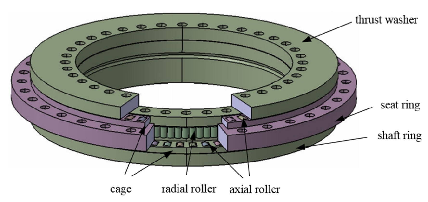
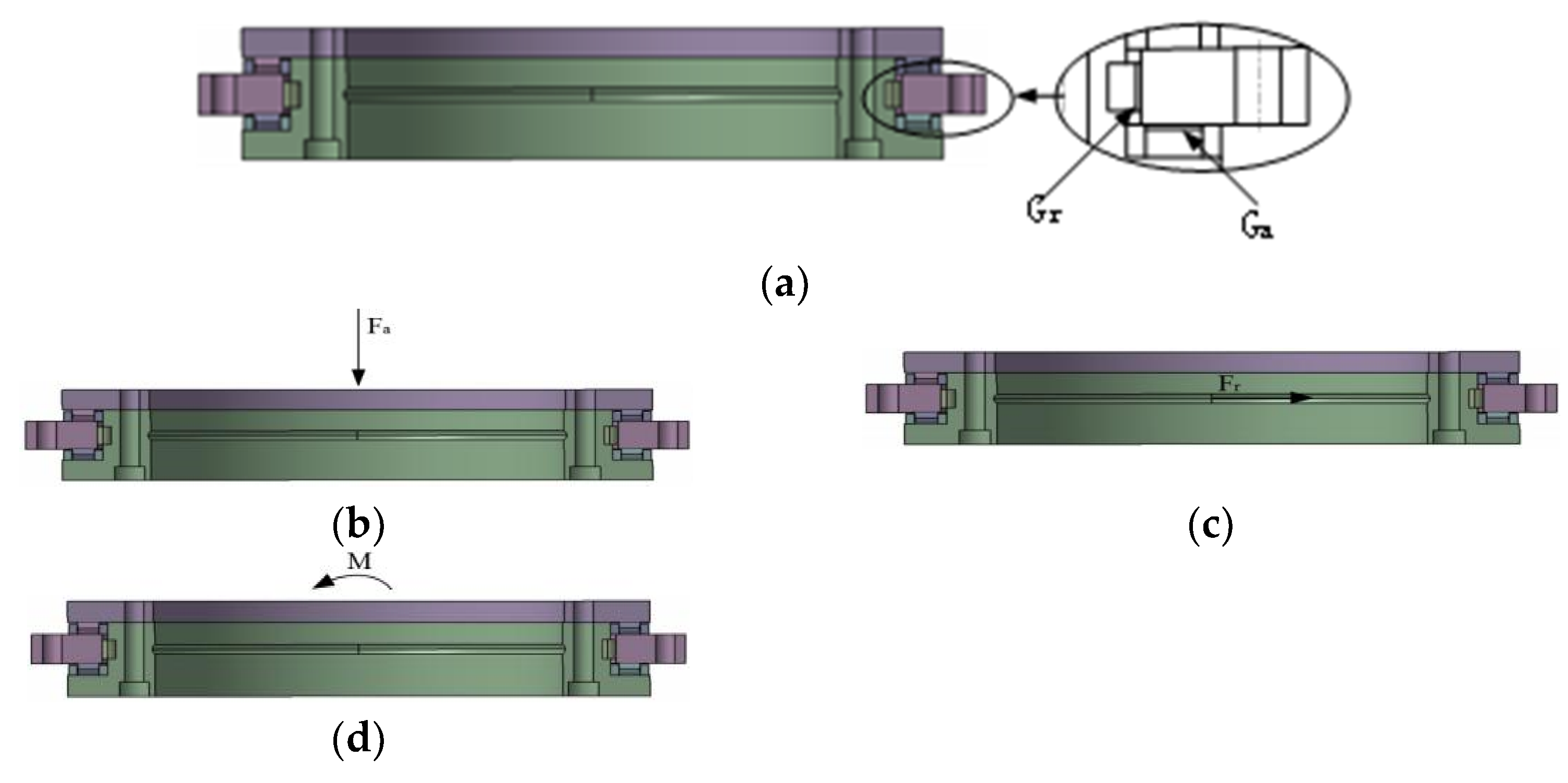
The YRT turntable bearing of the two-axis rotary table is composed of a shaft ring, a seat ring, two rows of axial cylindrical rollers, a row of radial cylindrical rollers, and a cage, as shown in Figure 2. To avoid convergence difficulties and enhance calculation efficiency in subsequent finite element calculation, the bearing model is simplified. First, it is assumed that when calculating the bearing stiffness theoretically, the race, washer and collar are considered as rigid bodies and will not deform under the action of force. The deformation area includes axial roller, radial roller and their contact area. The stay ring is fixed. Under the action of external force, the collar will have relative displacement. The rotating speed of the table does not exceed , and the centrifugal force is ignored. As shown in Figure 2, the axial direction of the YRT turntable bearing is composed of two rows of cylindrical rollers, which contact with two planes. The number of upper and lower rows of rollers is generally equal. Figure 3 shows the force and torque of the turntable bearing.
2.1. Axial Stiffness Modeling of Turntable Bearing
The axial force on the turntable bearing is illustrated in Figure 3b. According to the modified Palmgren cylindrical roller elasticity approximation formula [21], the load of a single axial roller can be expressed as
where is the load of a single axial roller, is the length of the roller, is the effective diameter of the axial roller, and is the axial elasticity-approaching quantity.
In the state of axial preload negative clearance Ga of YRT turntable bearing, the deformation of two rows of axial cylindrical rollers on each contact surface is equal; therefore, the elasticity-approaching quantity for the axial cylindrical rollers on each contact surface can be obtained from Equation (1) as follows:
When the total elasticity-approaching quantity change in the axial direction of the bearing is , the stiffness of the bearing is . At this time, the elasticity approach increase between the cylindrical roller and a contact surface is , and the increased load of a single roller is
The forces on each roller are equal in the state of negative axial clearance of the cylindrical roller bearing; in this state, the axial stiffness of the bearing can be calculated as follows:
where is the number of single-row axial cylindrical rollers.
The initial clearance of the axial roller is determined by the preload of the fastening screw. Under the action of an external load , the axial clearance [11] of the axial roller under the given tightening torque of the screw is
In Equation (5), Zb is the number of screws, T is the tightening torque, db is the screw diameter, Kb is the screw torque coefficient, and Kb is generally 0.2.
2.2. Radial Stiffness Modeling of Turntable Bearing
The radial force of the bearing is shown in Figure 3c. The elasticity-approaching quantity of the roller and the raceway of the cylindrical roller bearing with a line contact can be obtained from Equation (1):
where Qr is the load of the single radial roller, Lr is the length of the roller, Drw is the effective diameter of the roller, Zr is the number of radial cylindrical rollers, Fr is the radial load, k is the ratio of the effective diameter of the roller to the diameter of the raceway Drw/Dr, and Dr is the diameter of the raceway.
In the same way, axial stiffness of the bearing can be obtained as follows:
where Gr is the initial clearance of the radial roller.
2.3. Angular Stiffness Modeling of Turntable Bearing
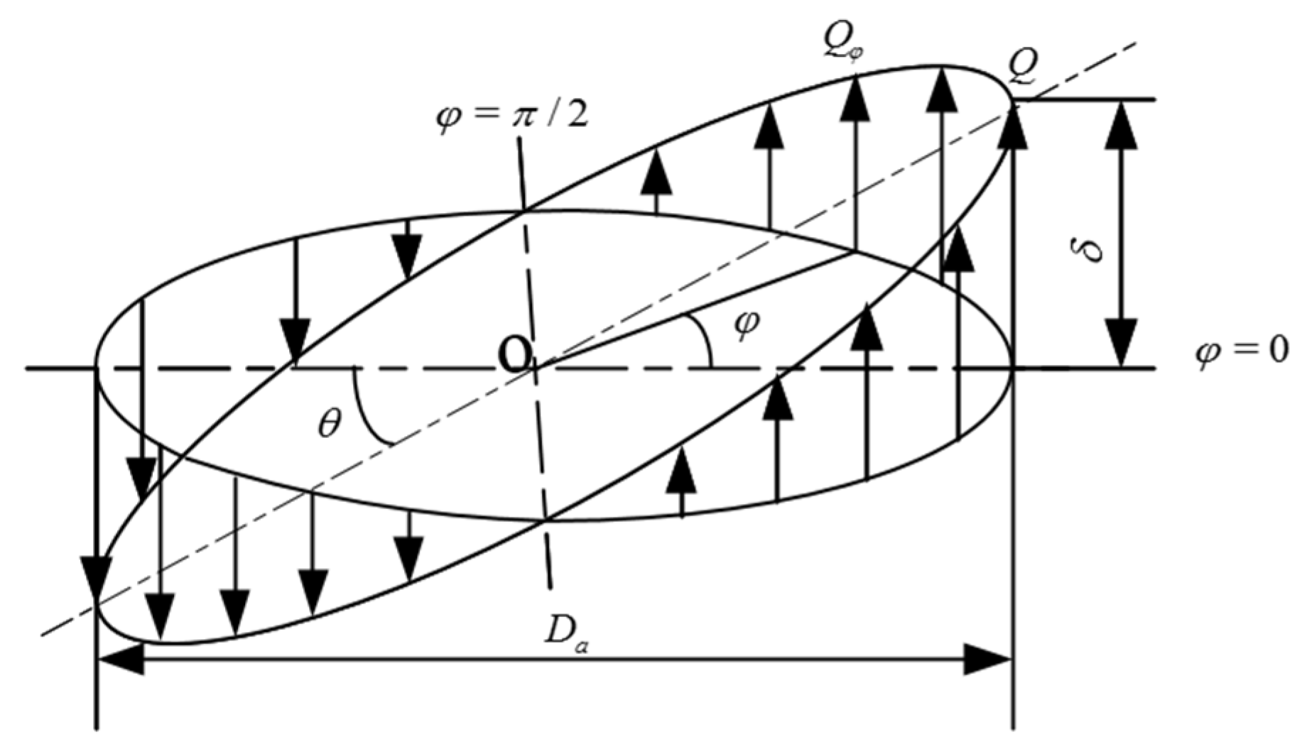
When the YRT turntable bearing is subjected to overturning moment , the inner ring will have a certain inclination angle relative to the outer ring owing to the uneven force of the circumferential roller. Both rows of thrust cylindrical rollers bear the overturning torque load. The torque load is shown in Figure 3d and its load distribution is shown in Figure 4.
As shown in Figure 4, Da is the axial roller raceway diameter. When the inclination angle is , i.e., . Equation (2) indicates that the load of the two raceways on the roller at the angular position φ is expressed as follows:
Then, at angular position φ, the roller load difference between the upper and lower raceways and the torque generated by the roller load difference are, respectively, as follows:
As shown in Figure 4, the moments generated by the left and right rollers are equal. By integrating the roller moment at each angular position, the moment balance equation is obtained as
By substituting Equations (8)–(10) into Equation (12), the moment load M when the inclination angle of the bearing is 1 m/rad can be calculated; that is, the angular stiffness KM in the negative clearance state (unit, Nm/rad) is obtained as follows:
From Equation (5), the axial clearance under the influence of external load is obtained as follows:
3. Analysis of Influencing Factors of Bearing Stiffness of Turntable
3.1. Effect of Clearance on Bearing Stiffness of Turntable
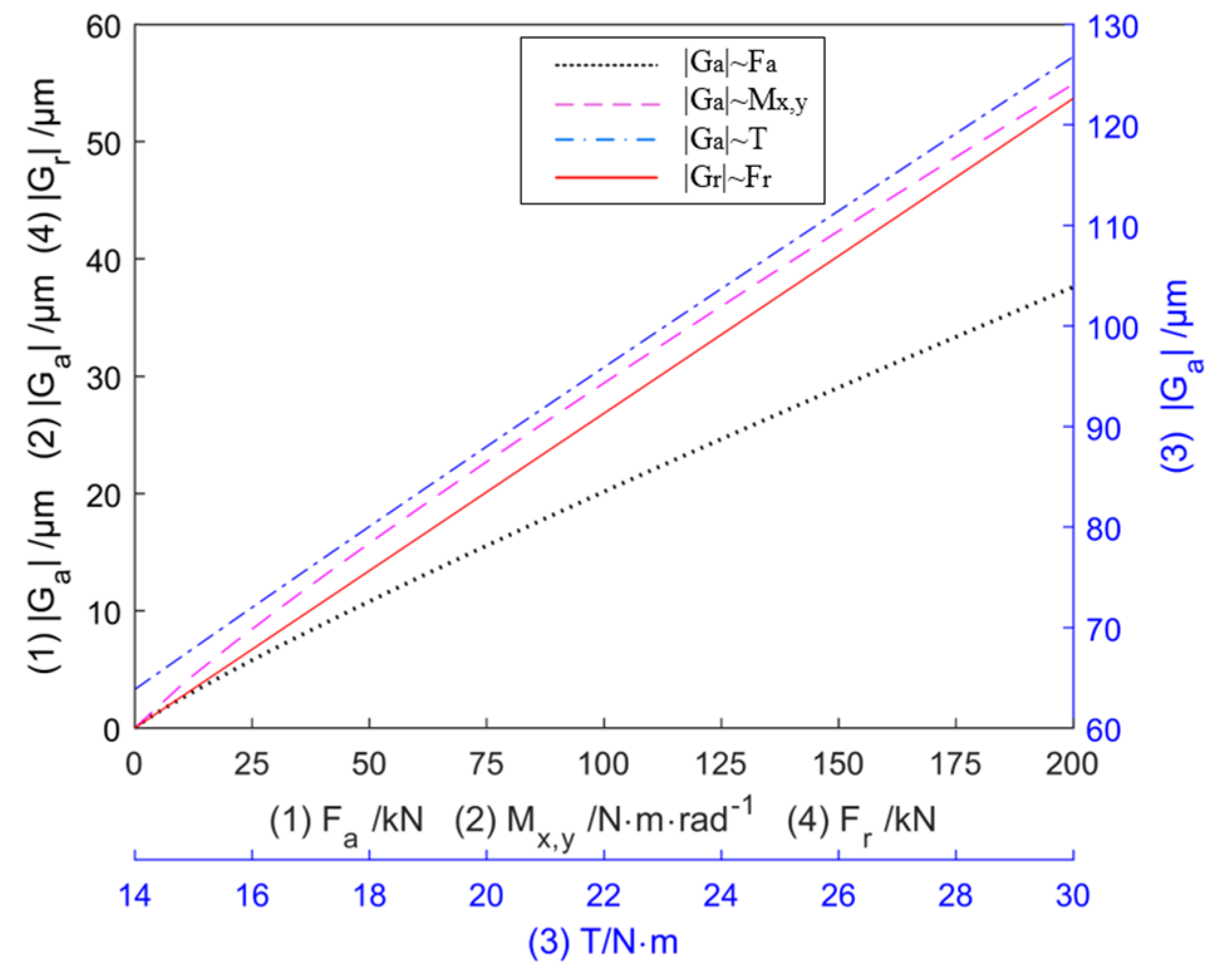
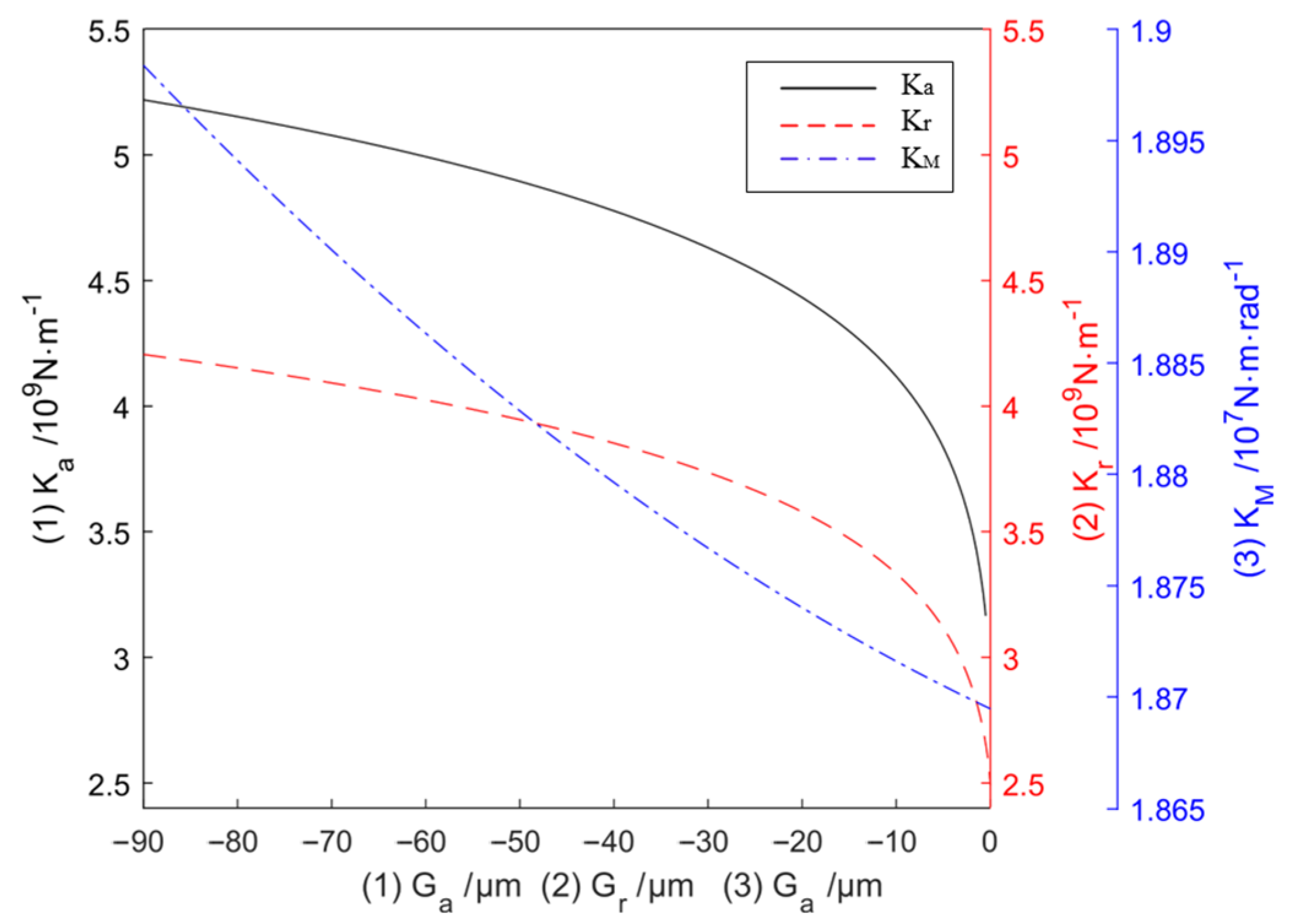
The initial parameters of the turntable bearing are listed in Table 1. According to Equations (5) and (14), the change in the actual clearance size of the axial roller under different screw tightening torque T, external load axial force , and external load torque can be obtained as shown in Figure 5. It can be seen that increases significantly with T, , and . Figure 6 shows the effect of the axial clearance of the turntable bearing on the stiffness of the turntable. When the axial clearance
increases with screw tightening torque T, both the axial stiffness and angular stiffness increase accordingly; specifically, increases more significantly, while increases gradually when increases to 20 µm. The radial clearance considerably affects the radial stiffness . However, more radial rollers are present than axial rollers; hence, the effect of on is not as obvious as that of on .
3.2. Effect of External Load on Bearing Stiffness of Turntable
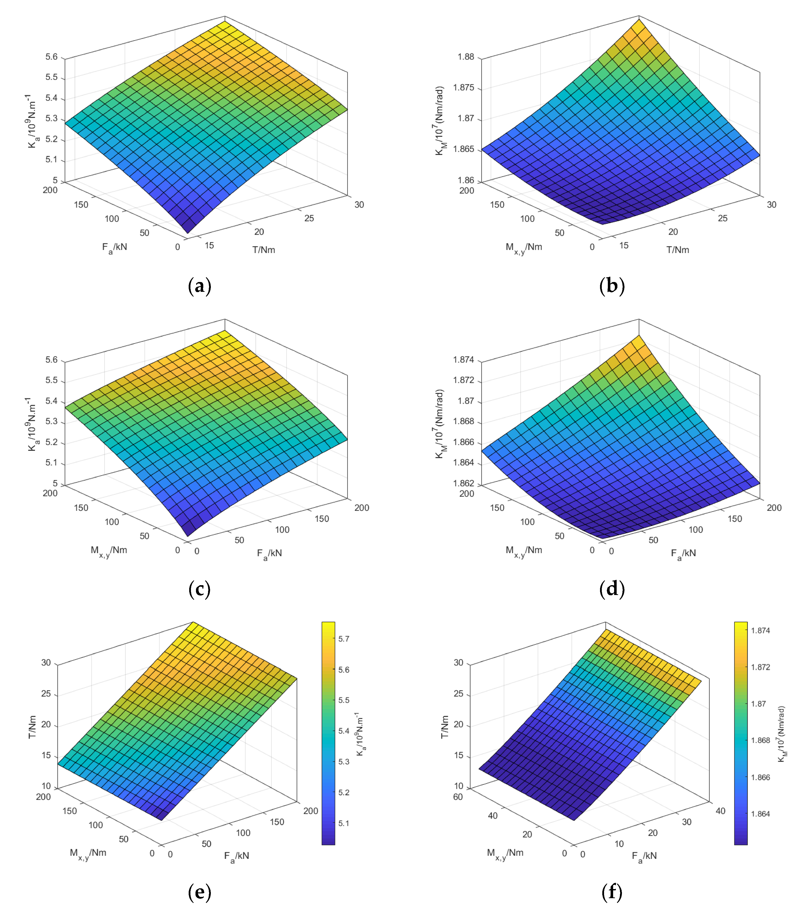
Under different screw tightening torques T, the variation law of axial stiffness of turntable bearing with external load and the variation law of angular stiffness with external load are shown in Figure 7e,f. It can be seen from Figure 7b,d,f that is insensitive to the change of , Mx,y and T, and the change is less than 2%. As shown in Figure 7a,c,e, increases with the increase in , Mx,y and T, and increases more obviously with the increase in Mx,y and T than with the increase in .
4. Analysis of Dynamic Characteristics of the Rotary System of the Turntable
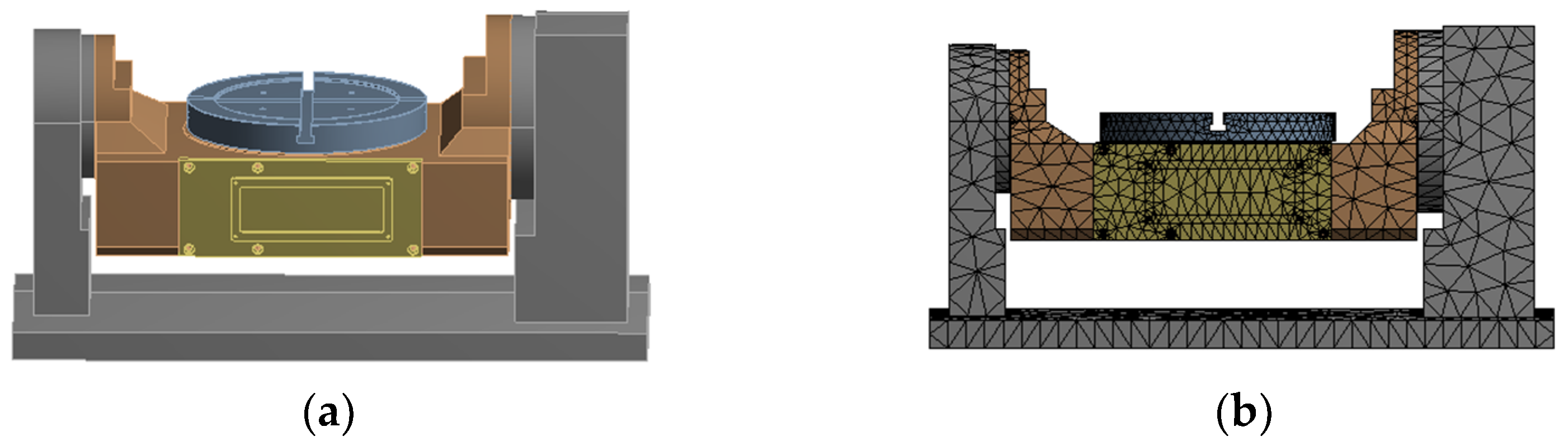
In order to build the geometric model of the rotary system in the 3D software, the rotary system was imported into the finite element analysis software and the finite element model was built. In order to achieve this, the following points need to be considered. To realize a reasonable shape of the unit generated by the finite element mesh division and improve the accuracy and efficiency of calculation and analysis, the structural model of the rotating system needs to be simplified before building the finite element model. Therefore, the following points are ensured: the main body of the rotary table is in the middle of the two-axis rotary table, including the table, the rotary table bearings, the worm gear and the main body; the holes, slots and chamfers of the rotary table are ignored. Figure 8a shows the structural model of the turntable.
During the finite element analysis, according to the solid modeling of the vertical machining center and its structural mechanical characteristics, the SOLID45 element is used in this analysis to set the boundary conditions of each joint surface and component. The fixed joint surface of the rotary table system is mainly bolted connection, and the default form is set. As shown in Table 2, the stiffness of the swing support bearing is set as axial stiffness 1.32 × 10⁸ N/m and radial stiffness 6.20 × 10⁷ N/m. The stiffness of the joint of the turntable bearing is set as axial stiffness 4.27 × 10⁹ N/m and radial stiffness 3.33 × 10⁹ N/m and angular stiffness 1.87 × 10⁷ N/m. Then, the table rotary system is meshed, and 124,354 grid units and 216,604 nodes are obtained. The grid model of the rotary table system is shown in Figure 8b.
4.1. Dynamic Characteristics Analysis of Rotary System at Different Swing Angles of the Turntable
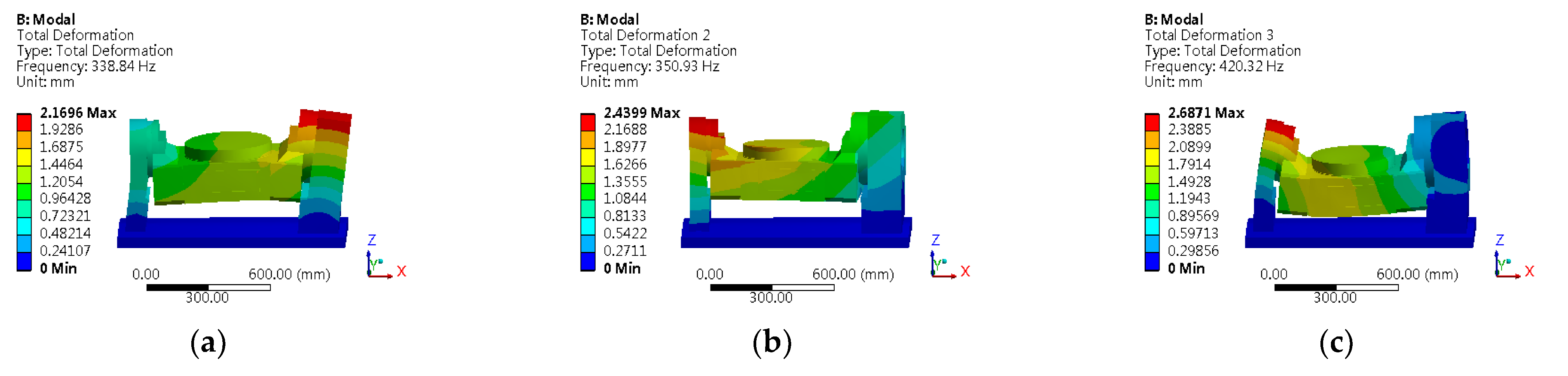
The rotary table shown in Figure 8 was used as the object of study. The dynamic characteristics (swing angle of the rotary table) of the rotary system of the five-axis machine tool were analyzed for the negative clearance of the turntable bearing. The modes of the rotary table at θ = 0° are shown in Figure 9, and the results are shown in Table 3.
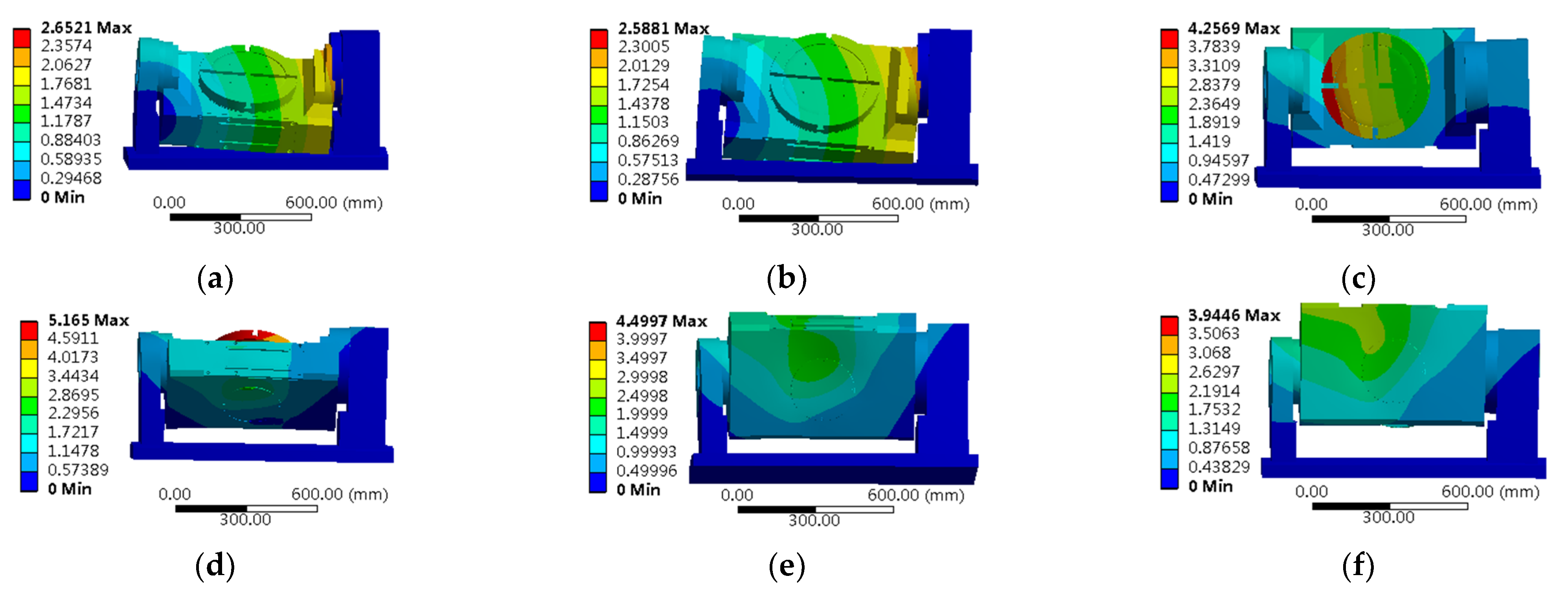
To analyze the effect of the dynamic characteristics of the rotary system under different swing angles of the turntable, the turntable shown in Figure 8 is considered as the research object. The dynamic characteristics of the turntable are analyzed at , , , and angles with or without considering the bearing stiffness of the turntable. The first six-order natural frequencies of the turntable under different angles of the turntable are calculated in the same way as shown in Figure 10 and Table 4. The structure and the swing angle of the turntable have great influence on its dynamic characteristics. The first-order natural frequencies of the turntable decrease with the turntable swing angle, and the natural frequencies of the positive angle of the turntable are larger than those of the corresponding negative angle. The maximum natural frequency is 338.84 Hz when the turntable swing angle is 0°. The minimum natural frequency is 261.41 Hz when the turntable swing angle is −90°. With varying angle, the first-order natural frequency of the turntable changes by 77.43 Hz.
4.2. Dynamic Characteristics Analysis of Rotary Table System under Different Bearing Stiffness of the Turntable
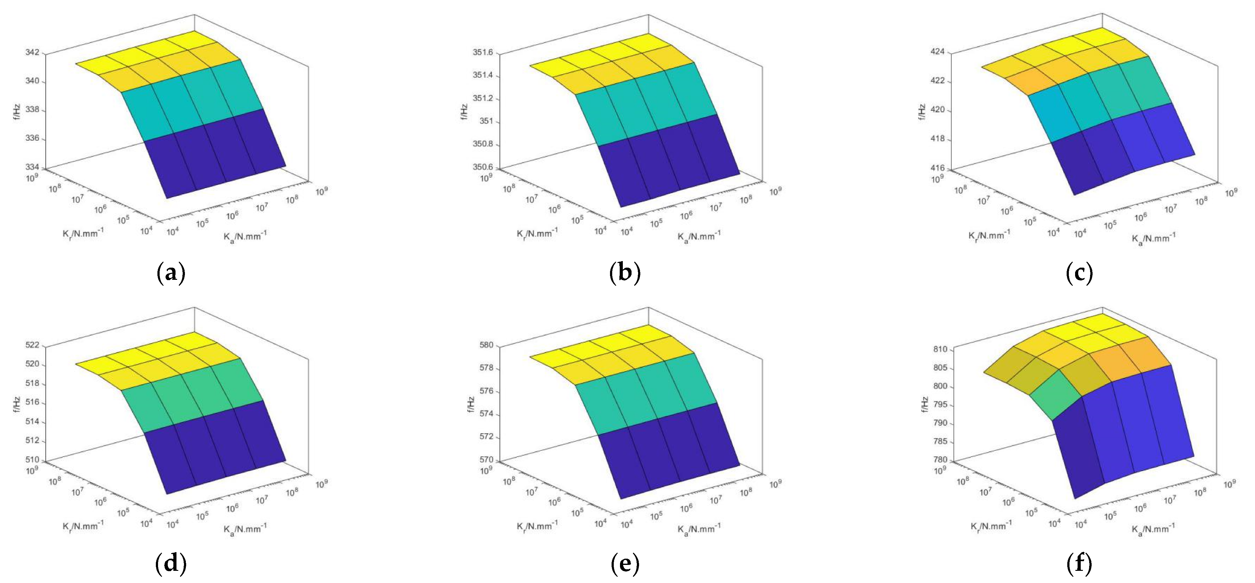
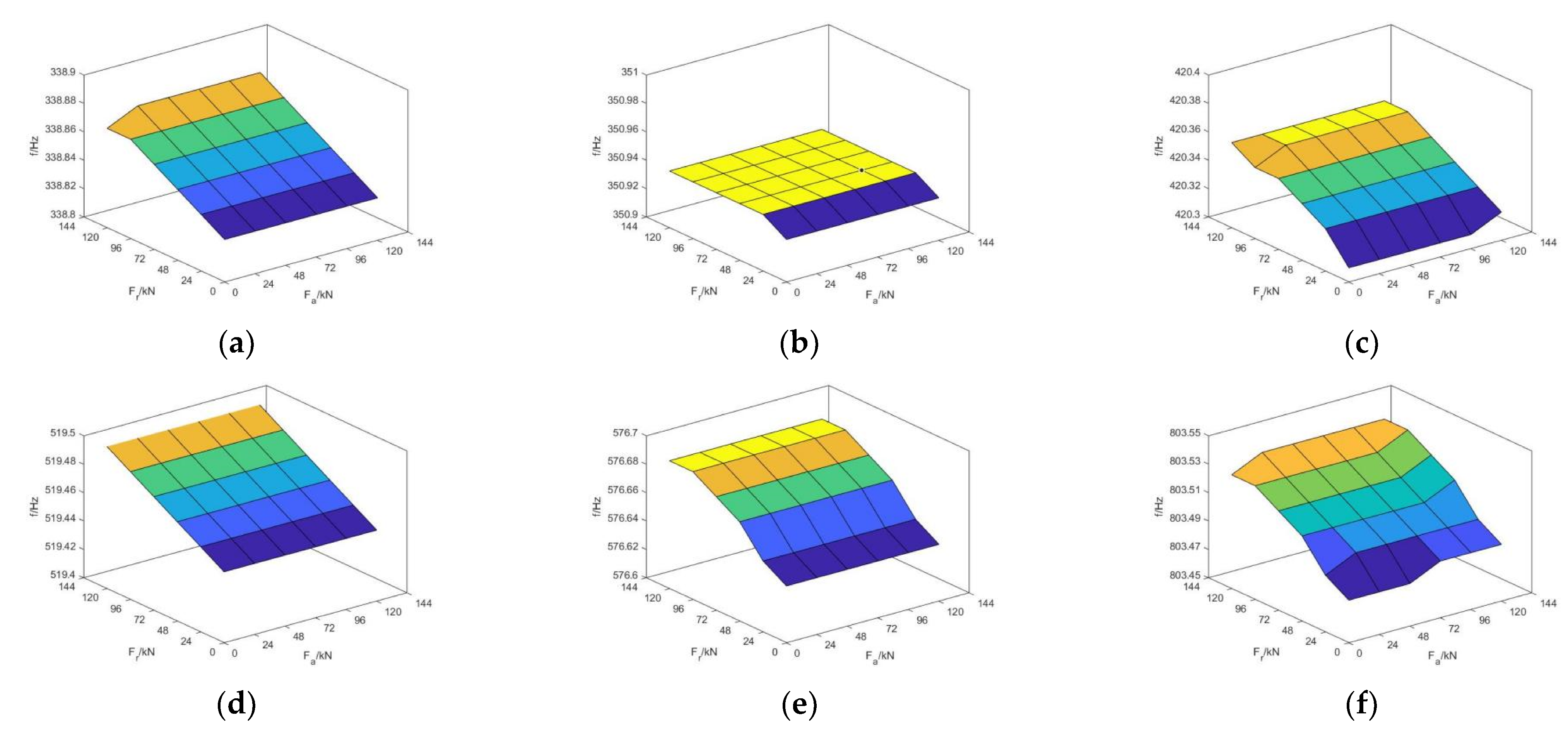
According to the analysis in Section 3.2, the stiffness of the turntable bearing is affected by the external load, and is insensitive to the change in the external load. Therefore, the influence of the angular stiffness of the bearing stiffness is ignored when studying the dynamic characteristics analysis of the turntable under different external loads. Take the turntable shown in Figure 8 as the research object to explore the dynamic characteristics of the swing system of the table under different bearing stiffness of the table. Set the swing angle as 0°, set the axial stiffness and radial stiffness of the turntable bearing of different sizes, and also simulate the dynamic characteristic parameters of the rotary table system in the way described in the previous section. The natural frequency of the turntable varies with the bearing stiffness of the turntable as shown in Figure 11. Similarly, when different sizes of external load axial force and radial force of turntable bearing are set, the natural frequency of the turntable changes with the external load of the turntable bearing, as shown in Figure 12.
As shown in Figure 11, in the process of changing the stiffness of the turntable bearing, the change in radial stiffness of the joint of the turntable bearing has a great influence on the natural frequency of the turntable. When the axial stiffness of the turntable bearing changes from 4.95 × 10⁵ N/mm to 4.95 × 10⁹ N/mm, and the radial stiffness changes from 3.95 × 10⁵ N/mm to 3.95 × 10⁹ N/mm, the first, second, fourth and fifth natural frequencies of the turntable will not change significantly with the axial stiffness of the turntable bearing joint, and the change in the first natural frequency is 30.3 Hz. The third and sixth order natural frequencies of the turntable increase with the increase in the axial and radial stiffness of the turntable bearing joint, and the increase in the radial stiffness is more obvious.
As shown in Figure 12, in the process of external axial force 0 to 120 kN and radial force 0 to 120 kN of the turntable bearing, the change in external load of turntable bearing has little influence on the natural frequency of the turntable, and the natural frequency of the turntable changes by less than 1 Hz. By comparing Figure 11 and Figure 12, it can be observed that under the same swing angle, the natural frequency of turntable is more dependent on the change in bearing stiffness than the change in limited external load on the turntable bearing.
5. Analysis of Dynamic Characteristics of Two Axis Rotary Table Five-Axis Machine Tool
In this study, the stiffness parameters of the equivalent joint surface of the two-axis rotary table five-axis machine tool are set on the basis of spring damping equivalence. Fixed binding has little effect on the dynamic characteristics and is set as the binding constraint.
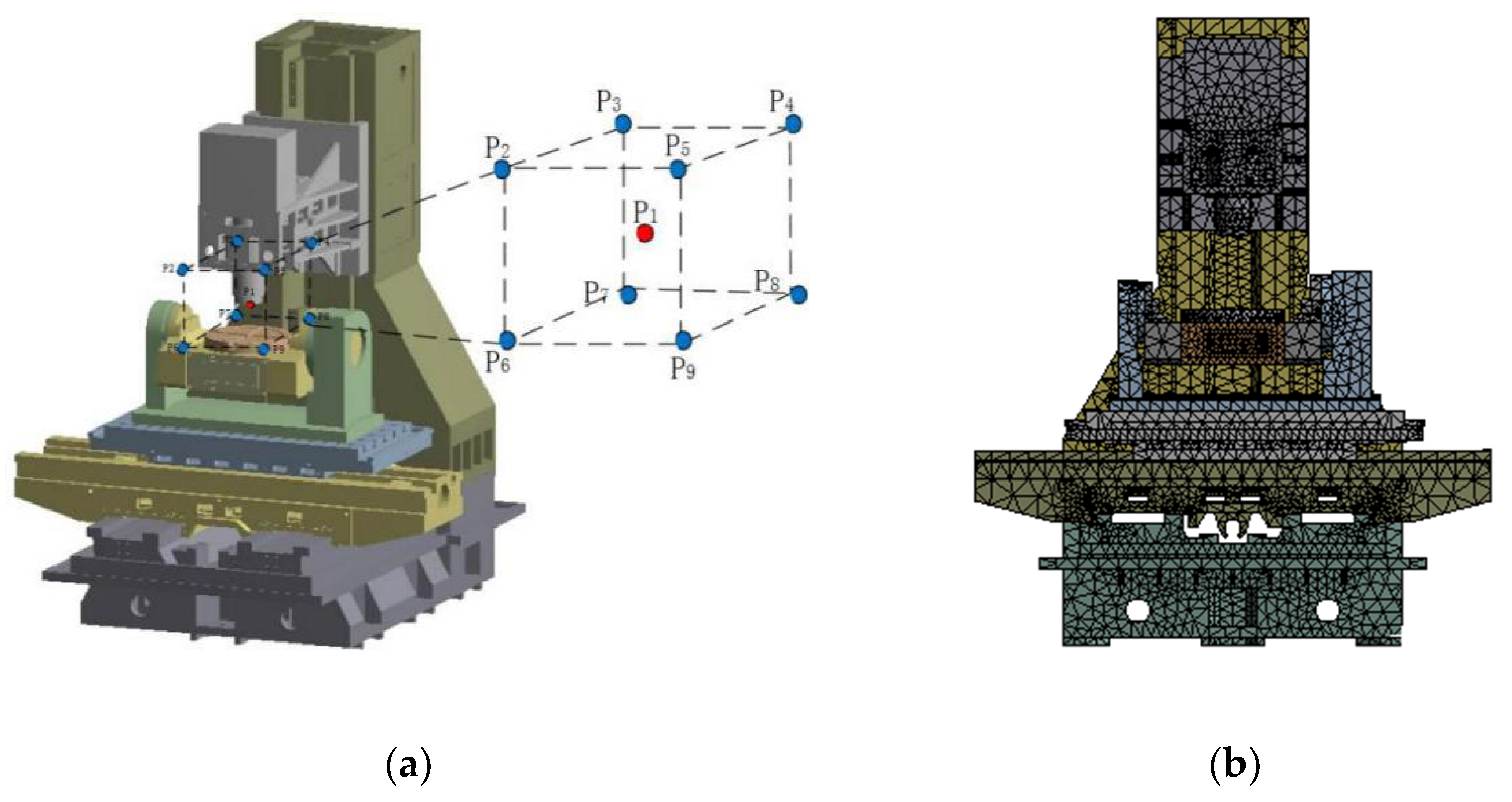
First, the three-dimensional model of five-axis machine tool Figure 13a are imported into the finite element simulation software, and the boundary conditions of each joint surface are set. The fixed joint surface of the five-axis machine tool with the two-axis rotary table is mainly connected by bolts. The stiffness of the joint part of the turntable bearing is set as described in the previous Section 4. The setting of the stiffness of the main motion joint surface is shown in Table 5. Next, as shown in Figure 13b, the whole machine is meshed into 524,232 mesh units and 831,997 nodes.
As shown in Figure 13a, the coordinate origin of the machining space of the machine tool in the reference system of the workbench is established, considering the coordinate origin (center point P1) as the center. A cube of side length of 300 mm is set as the machining space; each space has nine observation points. When the pendulum is at , , and , the observation position points are 9 × 5 = 45.
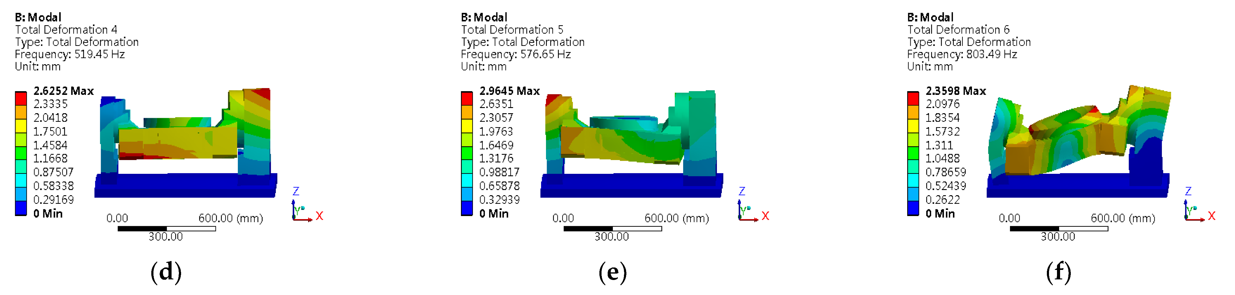
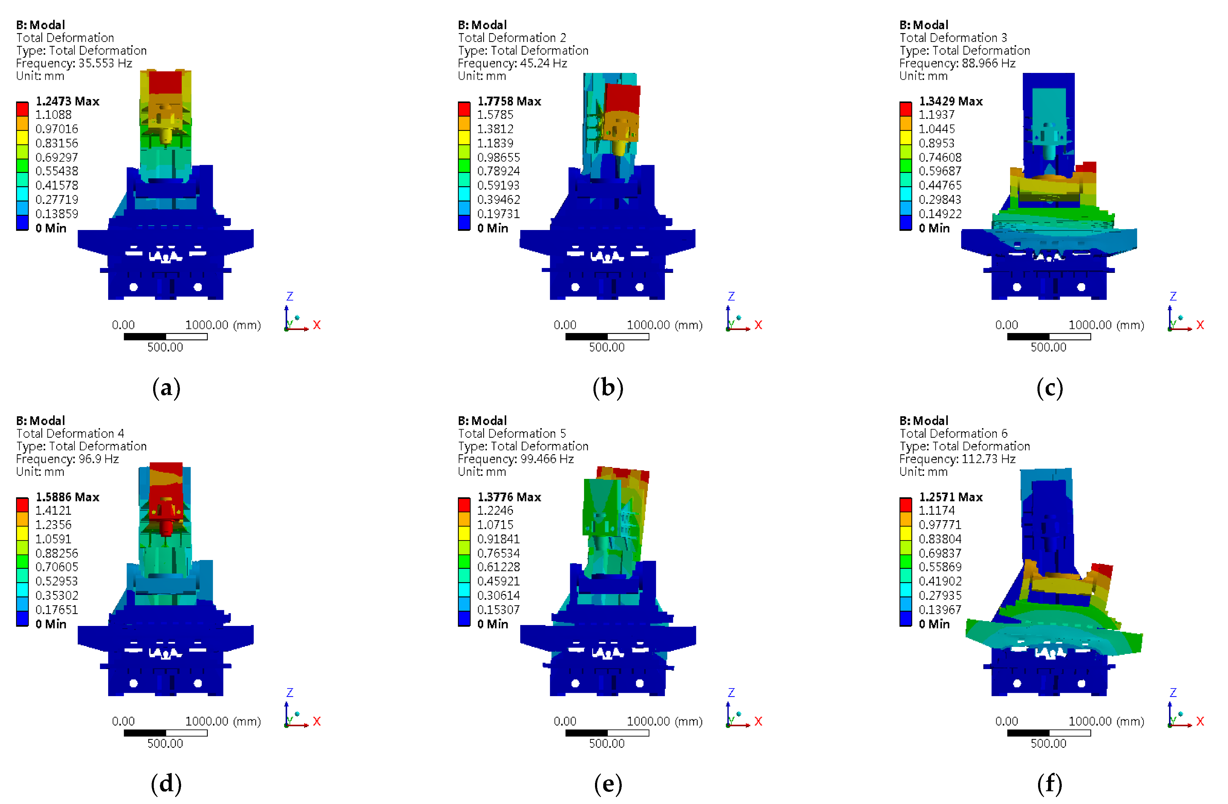
The double-pendulum five-axis machine tool’s spindle end’s 45 spatial positions are subjected to a modal analysis. Taking the spindle end at the coordinate origin X = 0 mm, Y = 0 mm, Z = 0 mm, θ = 0° as an example, the simulation results are shown in Figure 14, and the description of the modal parameters and modes is shown in Table 6.
Following the same method, as shown in Table 7, the modal analysis is performed for the 45 different machining positions of the spindle end.
The first-order natural frequencies of machine tools vary in the working space. As shown in Table 7, when the swing angle is , it is observed that the frequency of x-axis and y-axis changes slightly, while that of z-axis changes greatly. As the value of z-axis increases, the first-order natural frequency gradually decreases, with the variation at 3.01 Hz. When the table rotates at , , , , and , it is observed that the swing table angle of the machine tool has little influence on the first-order natural frequency of the machine tool, and the variation is approximately 3.00 Hz.
Therefore, the dynamic characteristics of the two-axis rotary table five-axis machine tool are mainly determined by the changes in its Z-axis. The higher position of the z-axis guide near the workbench, the higher first-order natural frequency of the machine tool. The swing angle of the turntable has no obvious influence on the dynamic characteristics of the whole machine tool.
6. Conclusions
- (1)
- The stiffness of the joint bearing of the rotary table system is calculated, and the effect of bearing clearance and external load on the stiffness is analyzed. The increase in the screw tightening torque T and external load Fa and Mx,y increases , which in turn increases Ka and KM accordingly. The increase in KM is significant, while Ka increases gradually when increases to 20 μm. As the radial clearance Kr increases, the radial stiffness first increases significantly and then tends to be stable.
- (2)
- When the swing angle of the turntable changes from −90° to 90°, the first-order natural frequency of the turntable decreases with the increase in the swing angle. The natural frequency of the positive angle is larger than that of the corresponding negative angle. When the swing angle is 0°, the natural frequency reaches the maximum (338.84 Hz), and when the swing angle is −90°, the natural frequency reaches the minimum (261.41 Hz). With the change in swing angle, the change in the first order natural frequency of the turntable is 77.43 Hz.
- (3)
- In the process of changing the turntable bearing stiffness, the change in the radial stiffness of the turntable bearing joint has a great influence on the natural frequency of the turntable. When the axial stiffness of the turntable bearing changes from 4.95 × 10⁵ N/mm to 4.95 × 10⁹ N/mm, and the radial stiffness changes from 3.95 × 10⁵ N/mm to 3.95 × 10⁹ N/mm, the first order natural frequency of the turntable does not change significantly with the axial stiffness of the turntable bearing joint, but increase with the increase in the radial stiffness of the turntable bearing joint, and the change in the first order natural frequency is 30.3 Hz. However, in the process of external axial force 0 to 120 kN and radial force 0 to 120 kN of the turntable bearing, the change in external load of turntable bearing has little influence on the natural frequency of the turntable, and the natural frequency of the turntable changes less than by 1 Hz.
- (4)
- The dynamic characteristic of the two-axis turntable five-axis machine tools mainly decided by the change in the Z-axis. The higher the Z-axis guide stays near the workbench, the higher is the first-order natural frequency of the machine tool.
Author Contributions
Conceptualization, S.W.; methodology, S.W.; software, W.L.; formal analysis, W.L.; data curation, S.W., W.L. and T.L.; writing—original draft preparation, S.W., W.L. and T.L.; writing—review and editing, S.W., W.L., Z.D. and T.Y.; All authors have read and agreed to the published version of the manuscript.
Funding
This research was funded by State Key Program of National Natural Science Foundation of China (51720105009).
Data Availability Statement
Not applicable.
Acknowledgments
This research was supported by the State Key Program of National Natural Science Foundation of China (51720105009).
Conflicts of Interest
The authors declare no conflict of interest.
References
- Lim, T.C.; Singh, R. Vibration transmission through rolling element bearings, part I: Bearing stiffness formulation. J. Sound Vibr. 1990, 139, 179–199. [Google Scholar] [CrossRef]
- Guo, Y.; Parker, R.G. Stiffness matrix calculation of rolling element bearings using a finite element/contact mechanics model. Mech. Mach. Theory 2012, 51, 32–45. [Google Scholar] [CrossRef]
- Gupta, T.C. Parametric studies on dynamic stiffness of ball bearings supporting a flexible rotor. J. Vib. Control 2019, 25, 2175–2188. [Google Scholar] [CrossRef]
- Hao, X.; Gu, X.; Zhou, X.; Liao, X.; Han, Q. Distribution characteristics of stress and displacement of rings of cylindrical roller bearing. Proc. Inst. Mech. Eng. Part C-J. Eng. Mech. Eng. Sci. 2019, 233, 4348–4358. [Google Scholar] [CrossRef]
- Göncz, P.; Drobne, M.; Glodež, S. Computational model for determination of dynamic load capacity of large three-row roller slewing bearings. Eng. Fail. Anal. 2013, 32, 44–53. [Google Scholar] [CrossRef]
- Li, Y.; Jiang, D. Strength check of a three-row roller slewing bearing based on a mixed finite element model. Proc. Inst. Mech. Eng. Part C-J. Eng. Mech. Eng. Sci. 2017, 231, 3393–3400. [Google Scholar] [CrossRef]
- Li, Y.F.; Lei, J. Determination of permissible contact stress of case hardened raceway of roller slewing bearing. Sci. Prog. 2020, 103, 0036850420980609. [Google Scholar]
- Wang, H.; He, P.; Pang, B.; Gao, X. A new computational model of large three-row roller slewing bearings using nonlinear springs. Proc. Inst. Mech. Eng. Part C-J. Eng. Mech. Eng. Sci. 2017, 231, 3831–3839. [Google Scholar] [CrossRef]
- He, P.; Liu, R.; Hong, R.; Wang, H.; Yang, G.; Lu, C. Hardened raceway calculation analysis of a three-row roller slewing bearing. Int. J. Mech. Sci. 2018, 137, 133–144. [Google Scholar] [CrossRef]
- He, P.; Wang, Y. Effect of high-strength bolts and supporting structures on the carrying capacity of three-row roller slewing bearings. Proc. Inst. Mech. Eng. Part C-J. Eng. Mech. Eng. Sci. 2021, 235, 2053–2064. [Google Scholar] [CrossRef]
- Wei, W.; Lv, D.; Zhang, J. Static stiffness modeling of turntable bearing and analysis of influencing factors. Acad. J. XJTU. 2014, 48, 8–14. [Google Scholar]
- Li, T.J.; Ding, X.H.; Cheng, K.; Wu, T. Dynamic optimization method with applications for machine tools based on approximation model. Proc. Inst. Mech. Eng. Part C-J. Eng. Mech. Eng. Sci. 2018, 232, 2009–2022. [Google Scholar] [CrossRef]
- Chen, Y.; Zhao, C.; Li, Z.; Lu, Z. Analysis on dynamic contact characteristics and dynamic stiffness estimating method of single nut ball screw pair based on the whole rolling elements model. Appl. Sci. 2020, 10, 5795. [Google Scholar] [CrossRef]
- Chen, H.; Tan, Z.; Tan, F.; Yin, G. Dynamic performance analysis and optimization method of the horizontal machining center based on contact theory. Int. J. Adv. Manuf. Technol. 2020, 108, 3055–3073. [Google Scholar] [CrossRef]
- Yu, H.; Ran, Y.; Zhang, G.; Ying, G. A dynamic time-varying reliability model for linear guides considering wear degradation. Nonlinear Dyn. 2021, 103, 699–714. [Google Scholar] [CrossRef]
- Liu, J.; Ma, C.; Wang, S.; Wang, S.; Yang, B. Contact stiffness of spindle-tool holder based on fractal theory and multi-scale contact mechanics model. Mech. Syst. Signal Proc. 2019, 119, 363–379. [Google Scholar] [CrossRef]
- Majumdar, A.; Bhushan, B. Fractal model of elastic-plastic contact between rough surfaces. J. Tribol-T. ASME. 1991, 113, 1–11. [Google Scholar] [CrossRef]
- Miao, X.; Huang, X. A complete contact model of a fractal rough surface. Wear 2014, 309, 146–151. [Google Scholar] [CrossRef]
- Li, D.; Botto, D.; Li, R.; Xu, C.; Zhang, W. Experimental and theoretical studies on friction contact of bolted joint interfaces. Int. J. Mech. Sci. 2022, 236, 107773. [Google Scholar] [CrossRef]
- Yuan, Y.; Xu, K.; Zhao, K. A fractal model of contact between rough surfaces for a complete loading–unloading process. Proc. Inst. Mech. Eng. Part C-J. Eng. Mech. Eng. Sci. 2020, 234, 2923–2935. [Google Scholar] [CrossRef]
- Harris, T.A.; Kotzalas, M.N. Rolling Bearing Analysis; Advanced Concepts of Bearing Technology; CRC Press: Boca Raton, FL, USA, 2006; pp. 209–256. [Google Scholar]
Figure 1.
Five-axis machine tool with two-axis rotary table; (a) Machine tool three-dimensional model; (b) Turntable structure diagram; (c) Section view of turntable structure.
Figure 1.
Five-axis machine tool with two-axis rotary table; (a) Machine tool three-dimensional model; (b) Turntable structure diagram; (c) Section view of turntable structure.

Figure 2.
Bearing structure diagram of the YRT turntable bearing.

Figure 3.
Bearing stress diagram of YRT turntable; (a) No schematic diagram of external force; (b) Schematic diagram of axial force; (c) Schematic diagram of radial force; (d) Schematic diagram of torque load.
Figure 3.
Bearing stress diagram of YRT turntable; (a) No schematic diagram of external force; (b) Schematic diagram of axial force; (c) Schematic diagram of radial force; (d) Schematic diagram of torque load.

Figure 4.
Load distribution under torque load.

Figure 5.
Variation of axial clearance with tightening torque T, external load axial force Fa and torque Mx,y.
Figure 5.
Variation of axial clearance with tightening torque T, external load axial force Fa and torque Mx,y.

Figure 6.
Variation of stiffness , , and with the clearance.

Figure 7.
Effect of external load on the bearing stiffness of the turntable; (a) Variation of with and T; (b) Variation of with Mx,y and T; (c) Variation of with and Mx,y ; (d) Variation of with and Mx,y ; (e) Variation of with , Mx,y and T; (f) Variation of with , Mx,y and T.
Figure 7.
Effect of external load on the bearing stiffness of the turntable; (a) Variation of with and T; (b) Variation of with Mx,y and T; (c) Variation of with and Mx,y ; (d) Variation of with and Mx,y ; (e) Variation of with , Mx,y and T; (f) Variation of with , Mx,y and T.

Figure 8.
Three-dimensional model and meshing of the rotary system of the turntable; (a) Three-dimensional model drawing; (b) Grid model diagram.
Figure 8.
Three-dimensional model and meshing of the rotary system of the turntable; (a) Three-dimensional model drawing; (b) Grid model diagram.

Figure 9.
First six modes of turntable; (a) First mode; (b) Second mode; (c) Third mode; (d) Fourth mode; (e) Fifth mode; (f) Sixth mode.
Figure 9.
First six modes of turntable; (a) First mode; (b) Second mode; (c) Third mode; (d) Fourth mode; (e) Fifth mode; (f) Sixth mode.


Figure 10.
The first mode of the turntable at different swing angles; (a) 30°; (b) 60°; (c) 90°; (d) −30°; (e) −60°; (f) −90°.
Figure 10.
The first mode of the turntable at different swing angles; (a) 30°; (b) 60°; (c) 90°; (d) −30°; (e) −60°; (f) −90°.

Figure 11.
Variation of the first six-order natural frequencies of the rotary table with the bearing stiffness of the turntable; (a) Variation of first-order frequency; (b) Variation of second-order frequency; (c) Variation of third-order frequency; (d) Variation of fourth-order frequency; (e) Variation of fifth-order frequency; (f) Variation of sixth-order frequency.

Figure 12.
Variation of the first six-order natural frequencies of the bearing load of the turntable; (a) Variation of first-order frequency; (b) Variation of second-order frequency; (c) Variation of third-order frequency; (d) Variation of fourth-order frequency; (e) Variation of fifth-order frequency; (f) Variation of sixth-order frequency.

Figure 13.
Machine tool processing space and grid division; (a) Machine tool processing space; (b) Machine tool grid division.
Figure 13.
Machine tool processing space and grid division; (a) Machine tool processing space; (b) Machine tool grid division.

Figure 14.
Modal results of the machine tool at the coordinate origin x = 0 mm, z = 0 mm, y = 0 mm, θ = 0°; (a) First mode; (b) Second mode; (c) Third mode; (d) Fourth mode; (e) Fifth mode; (f) Sixth mode.
Figure 14.
Modal results of the machine tool at the coordinate origin x = 0 mm, z = 0 mm, y = 0 mm, θ = 0°; (a) First mode; (b) Second mode; (c) Third mode; (d) Fourth mode; (e) Fifth mode; (f) Sixth mode.


Table 1.
Initial parameters of the turntable bearing.
| Parameters | Value |
|---|---|
| Number of axial radial rollers Za, Zr | 70, 115 |
| Axial radial roller diameter Daw, Drw/mm | 5, 5 |
| Axial radial roller length La, Lr/mm | 8, 8 |
| Diameter of axial radial roller raceway Da, Dr/mm | 199, 183.5 |
| Number of screws Zb | 36 |
| Screw diameter db/mm | 7 |
Table 2.
Turntable joint stiffness.
| Type of Junction | Axial Stiffness (N/m) | Radial Stiffness (N/m) | Angular Stiffness (N/m) |
|---|---|---|---|
| Turntable supports Bearing joint | - | ||
| - | |||
| Turntable bearing joint | |||
| Worm gear and worm Pair joint | - |
Table 3.
First six-order natural frequencies of the turntable.
| Mode Order | 1th | 2th | 3th | 4th | 5th | 6th |
|---|---|---|---|---|---|---|
| Theoretical value/Hz | 338.84 | 350.93 | 420.32 | 519.45 | 576.65 | 803.49 |
| Theoretical vibration mode | X-direction bending vibration of worktable | Y-direction bending vibration of worktable | Z-direction bending vibration of worktable | X-direction torsional vibration of table | Z-direction torsional vibration of table | Y-direction torsional vibration of table |
Table 4.
First six-order natural frequencies of the turntable at different swing angles.
| Mode Order Theoretical Value/Hz | 1th | 2th | 3th | 4th | 5th | 6th |
|---|---|---|---|---|---|---|
| 0° (the swing angles of the turntable)/Hz | 338.84 | 350.93 | 420.32 | 519.45 | 576.65 | 803.49 |
| 30° | 320.24 | 352.23 | 462.45 | 517.91 | 569.32 | 805.48 |
| −30° | 313.13 | 348.52 | 463.74 | 522.77 | 554.97 | 823.51 |
| 60° | 291.93 | 350.75 | 501.87 | 545.23 | 562.45 | 833.19 |
| −60° | 280.96 | 349.02 | 498.07 | 530.73 | 568.04 | 870.91 |
| 90° | 271.83 | 329.28 | 495.88 | 533.42 | 677 | 855.99 |
| −90° | 261.41 | 328.54 | 488.72 | 540.1 | 679.81 | 907.91 |
Table 5.
Machine tool joint stiffness.
| Type of Junction | Interface Structure | Axial Stiffness (N/µm) | Normal Stiffness (N/µm) |
|---|---|---|---|
| Linear guide pair | Cradle and bed | - | 348 |
| Slide rails and beams | - | 326 | |
| Spindle and slide rails | - | 304 | |
| Slide rails and columns | - | 305 | |
| Ball screw pair | Cradle and bed | 267 | - |
| Slide rails and spindle | 262 | - | |
| Slide rails and beams | 253 | - | |
| Slide rails and columns | 257 | - |
Table 6.
First six-order natural frequencies of a two-axis rotary table five-axis machine tool.
| Mode Order | 1th | 2th | 3th | 4th | 5th | 6th |
|---|---|---|---|---|---|---|
| Theoretical value/Hz | 35.55 | 45.24 | 88.97 | 96.90 | 99.47 | 112.73 |
| Theoretical vibration mode | Y-direction bending vibration of column | X-direction bending vibration of spindle box | Y-direction bending vibration of worktable | Y-direction bending vibration of spindle box | Z-direction torsional vibration of column | X-direction bending vibration of worktable |
Table 7.
Machine tool modal parameters at different positions of the spindle end.
| Spindle End Position Parameters (mm) | f1 (Hz) | f2 (Hz) | f3 (Hz) | f4 (Hz) | f5 (Hz) | f6 (Hz) | |||
|---|---|---|---|---|---|---|---|---|---|
| 0° | 0 | 0 | 0 | 35.55 | 45.24 | 88.97 | 96.90 | 99.47 | 112.73 |
| 0° | −150 | −150 | 150 | 34.05 | 43.35 | 86.82 | 94.19 | 98.89 | 106.78 |
| 0° | −150 | 150 | 150 | 34.04 | 43.33 | 83.54 | 94.16 | 99.26 | 105.38 |
| 0° | 150 | 150 | 150 | 34.04 | 43.33 | 86.72 | 94.34 | 99.30 | 110.78 |
| 0° | 150 | −150 | 150 | 34.05 | 43.35 | 89.79 | 94.47 | 99.05 | 112.24 |
| 0° | −150 | −150 | −150 | 37.06 | 46.95 | 86.88 | 98.32 | 99.13 | 106.95 |
| 0° | −150 | 150 | −150 | 37.05 | 46.93 | 83.58 | 98.32 | 99.56 | 105.45 |
| 0° | 150 | 150 | −150 | 37.05 | 46.93 | 86.82 | 98.47 | 99.60 | 110.83 |
| 0° | 150 | −150 | −150 | 37.06 | 46.95 | 89.98 | 98.49 | 99.32 | 112.39 |
| 30° | 0 | 0 | 0 | 35.54 | 45.25 | 88.61 | 96.89 | 99.45 | 112.88 |
| 30° | −150 | −150 | 150 | 34.04 | 43.37 | 86.38 | 94.19 | 98.86 | 106.81 |
| 30° | −150 | 150 | 150 | 34.03 | 43.35 | 83.27 | 94.17 | 99.25 | 105.46 |
| 30° | 150 | 150 | 150 | 34.03 | 43.35 | 86.36 | 94.32 | 99.29 | 110.86 |
| 30° | 150 | −150 | 150 | 34.04 | 43.37 | 89.37 | 94.42 | 99.04 | 112.34 |
| 30° | −150 | −150 | −150 | 37.04 | 46.95 | 86.43 | 98.29 | 99.09 | 106.99 |
| 30° | −150 | 150 | −150 | 37.03 | 46.93 | 83.30 | 98.30 | 99.54 | 105.55 |
| 30° | 150 | 150 | −150 | 37.03 | 46.93 | 86.45 | 98.43 | 99.58 | 110.91 |
| 30° | 150 | −150 | −150 | 37.04 | 46.95 | 89.52 | 98.44 | 99.29 | 112.48 |
| 60° | 0 | 0 | 0 | 35.54 | 45.25 | 86.83 | 96.80 | 99.43 | 112.24 |
| 60° | −150 | −150 | 150 | 34.04 | 43.37 | 84.67 | 94.13 | 98.78 | 106.10 |
| 60° | −150 | 150 | 150 | 34.03 | 43.35 | 81.71 | 94.12 | 99.21 | 104.74 |
| 60° | 150 | 150 | 150 | 34.03 | 43.35 | 84.67 | 94.23 | 99.28 | 110.19 |
| 60° | 150 | −150 | 150 | 34.04 | 43.37 | 87.54 | 94.25 | 99.01 | 111.69 |
| 60° | −150 | −150 | −150 | 37.04 | 46.95 | 84.70 | 98.25 | 98.99 | 106.30 |
| 60° | −150 | 150 | −150 | 37.03 | 46.93 | 81.73 | 98.26 | 99.49 | 104.83 |
| 60° | 150 | 150 | −150 | 37.03 | 46.93 | 84.73 | 98.36 | 99.57 | 110.25 |
| 60° | 150 | −150 | −150 | 37.04 | 46.95 | 87.61 | 98.35 | 99.25 | 111.82 |
| −30° | 0 | 0 | 0 | 35.54 | 45.25 | 88.01 | 96.85 | 99.47 | 112.27 |
| −30° | −150 | −150 | 150 | 34.04 | 43.37 | 85.78 | 94.16 | 98.87 | 106.20 |
| −30° | −150 | 150 | 150 | 34.03 | 43.35 | 82.73 | 94.15 | 99.26 | 104.85 |
| −30° | 150 | 150 | 150 | 34.03 | 43.35 | 85.74 | 94.29 | 99.31 | 110.36 |
| −30° | 150 | −150 | 150 | 34.04 | 43.37 | 88.73 | 94.35 | 99.07 | 111.73 |
| −30° | −150 | −150 | −150 | 37.04 | 46.95 | 85.81 | 98.28 | 99.09 | 106.38 |
| −30° | −150 | 150 | −150 | 37.03 | 46.93 | 82.76 | 98.29 | 99.55 | 104.93 |
| −30° | 150 | 150 | −150 | 37.03 | 46.93 | 85.81 | 98.41 | 99.61 | 110.41 |
| −30° | 150 | −150 | −150 | 37.04 | 46.95 | 88.84 | 98.41 | 99.32 | 111.86 |
| −60° | 0 | 0 | 0 | 35.54 | 45.25 | 85.80 | 96.76 | 99.47 | 111.27 |
| −60° | −150 | −150 | 150 | 34.04 | 43.37 | 83.62 | 94.10 | 98.80 | 105.10 |
| −60° | −150 | 150 | 150 | 34.03 | 43.35 | 80.78 | 94.10 | 99.23 | 103.75 |
| −60° | 150 | 150 | 150 | 34.03 | 43.35 | 83.62 | 94.19 | 99.31 | 109.37 |
| −60° | 150 | −150 | 150 | 34.04 | 43.37 | 86.44 | 94.19 | 99.06 | 110.71 |
| −60° | −150 | −150 | −150 | 37.04 | 46.95 | 83.64 | 98.24 | 99.00 | 105.29 |
| −60° | −150 | 150 | −150 | 37.03 | 46.93 | 80.79 | 98.25 | 99.50 | 103.85 |
| −60° | 150 | 150 | −150 | 37.03 | 46.93 | 83.66 | 98.33 | 99.60 | 109.42 |
| −60° | 150 | −150 | −150 | 37.04 | 46.95 | 86.48 | 98.32 | 99.31 | 110.84 |
Disclaimer/Publisher’s Note: The statements, opinions and data contained in all publications are solely those of the individual author(s) and contributor(s) and not of MDPI and/or the editor(s). MDPI and/or the editor(s) disclaim responsibility for any injury to people or property resulting from any ideas, methods, instructions or products referred to in the content. |
© 2023 by the authors. Licensee MDPI, Basel, Switzerland. This article is an open access article distributed under the terms and conditions of the Creative Commons Attribution (CC BY) license (https://creativecommons.org/licenses/by/4.0/).
Share and Cite
MDPI and ACS Style
Wu, S.; Lei, W.; Yu, T.; Dong, Z.; Liu, T. Effect of the Stiffness of the Turntable Bearing Joint on the Dynamic Characteristics of the Five-Axis Machine Tool Rotary System. Machines 2023, 11, 389. https://doi.org/10.3390/machines11030389
AMA Style
Wu S, Lei W, Yu T, Dong Z, Liu T. Effect of the Stiffness of the Turntable Bearing Joint on the Dynamic Characteristics of the Five-Axis Machine Tool Rotary System. Machines. 2023; 11(3):389. https://doi.org/10.3390/machines11030389
Chicago/Turabian StyleWu, Shi, Weijie Lei, Tai Yu, Zeyu Dong, and Taorui Liu. 2023. "Effect of the Stiffness of the Turntable Bearing Joint on the Dynamic Characteristics of the Five-Axis Machine Tool Rotary System" Machines 11, no. 3: 389. https://doi.org/10.3390/machines11030389
Note that from the first issue of 2016, this journal uses article numbers instead of page numbers. See further details here.