Article

A Coyote Optimization-Based Residual Attention Echo State Reactive Controller for Improving Power Quality in Grid-PV Systems

by
Rathinam Marimuthu Sekar
1,
Sankar Murugesan
2,
Ghanta Devadasu
3 and
Surender Reddy Salkuti
4,*
1
Department of Electrical and Electronics Engineering, PSNA College of Engineering and Technology, Dindigul 624622, Tamil Nadu, India
2
Department of Computer Science and Engineering, Vel Tech Rangarajan Dr. Sagunthala R&D Institute of Science and Technology, Avadi, Chennai 600062, Tamil Nadu, India
3
Department of Electrical and Electronics Engineering, CMR College of Engineering and Technology, Hyderabad 501401, Telangana, India
4
Department of Railroad and Electrical Engineering, Woosong University, Daejeon 34606, Republic of Korea
*
Author to whom correspondence should be addressed.
Machines 2023, 11(3), 384; https://doi.org/10.3390/machines11030384
Submission received: 31 December 2022 / Revised: 1 March 2023 / Accepted: 9 March 2023 / Published: 14 March 2023
(This article belongs to the Section Electrical Machines and Drives)

Abstract

:
Improving the power quality and reactive injection capability of grid-PV systems represent the most demanding and crucial tasks in power systems. In the conventional works, many types of converters and regulating approaches have been designed for this goal. The multi-level inverter (MLI) is the best solution for grid-PV systems since it helps to improve power quality while reducing losses. However, the existing works face the key problems of the complex system model, increased components utilization, computational burden, presence of harmonics, and high switching frequency. Therefore, the proposed work aims to develop novel and advanced controlling techniques for improving the reactive power compensation ability and power quality of grid-PV systems. The original contribution of this paper is to implement an advanced soft-computing methodologies for developing the controlling mechanisms. At first, an ATOM search optimization (AOS) based MPPT controlling technique is used to extract the maximum electrical energy from the PV panels under changing climatic situations. Then, the output voltage of PV is effectively regulated with the help of a non-isolated high voltage gain DC-DC converter, which also supports the reduction of the switching loss and frequencies. In order to generate the switching pulses for operating the converter, a novel coyote optimized converter control (COCC) mechanism is developed in this work. Moreover, a residual attention echo state reactive controller (RaERC) is implemented for generating the controlling signals to actuate the switching components of the nine-level inverter. This kind of controlling mechanism could highly improve the power quality of grid system with less processing time. For assessment, the simulation and comparison results of the proposed controlling mechanisms are validated and tested using various parameters.

1. Introduction

In recent times, the renewable energy sources (RES) [1,2] have been widely used in many applications owing to their benefits eco-logical nature, reduced cost, zero emissions, etc. Among other sources, solar photovoltaic (PV) [3,4,5] systems are mainly used in most of the power system applications, since it effectively satisfying the energy demands with minimal cost consumption. However, extracting the maximum solar energy [6,7,8] from the PV panels remains one of the challenging tasks due to varying changing climatic conditions. Due to their inherent ability to handle high voltages, multi-level inverters (MLIs) [6,9,10] have been extensively used in a variety of modern applications. MLIs can give multiple levels of output with the least amount of composition when switching out appliances. Unlike the traditional single level inverter, the multilevel inverter [11,12,13,14] serves as the score seeding for multi switching. MLI has the ability to generate typical output voltage levels by switching inverter groups. In the case of MLI [15,16,17,18,19], the output provided by the converter will also have a considerably decreased output waveform as the level of voltage rises. In addition, the key benefits of using MLI in grid-PV systems [20,21,22,23] are as follows:
  • Increased power quality
  • Minimal switching loss
  • Reduced harmonics
  • Better compatibility
However, the reactive power compensation and power quality improvement in grid-PV systems [24,25,26,27] using multilevel inverter are the major and very challenging processes. In the existing works [28,29,30], the different types of controlling techniques, converter and inverter topologies used for power quality improvement and reactive power compensation. Stonier et al. [31] deployed a cascaded multilevel inverter topology for improving the quality of power in the solar PV systems. This work mainly objects to regulate the output voltage by properly maintaining the inverter output voltage and frequency. Here, three different types of inverter controlling technique, i.e., PI, FLC, and ANN, have been implemented to efficiently resolve the power quality problems. However, this required to reduce the level of harmonics in order to ensure better system performance. Prasad et al. [32] deployed a dynamic voltage restorer (DVR) incorporated with 23-level inverter topology for enhancing the power quality of grid-connected systems. Here, the purpose of using this inverter topology was to minimize the cost, count, and size of components used in the circuit design. In addition, the incremental conductance based MPPT [33] controlling technique has been deployed to obtain the maximum power from the PV panels. The key benefits of this work were reduced voltage sag, swell, and enhanced power quality. Yet, it could be very difficult to understand the system model, which degrades the performance of entire model. Dhineshkumar et al. [34] utilized a nine-level inverter for resolving the power quality problems in the solar PV systems. Here, the boost DC-DC converter was utilized to increase the voltage gain output with reduced loss.
In order to pinpoint the problems with producing more levels at the output, research is [35] conducted on various multilevel inverter types, including symmetric, asymmetric, hybrid, and modularized multilevel inverters. In order to build a novel multilevel inverter topology in the future, a summary of the significant challenges in multilevel inverters with reduced switch counts is offered. Different symmetrical, asymmetrical, and hybrid MLI topologies [36] were created using different numbers of switches, capacitors, and diodes in the inverter circuit. Additionally, all setups’ total standing voltages and THD generation are analyzed. Using a novel switched source, MLI [37] can function in symmetric and asymmetric modes is suggested. Six power switches and two voltage sources are included in the design of the proposed inverter. In order to increase system stability by lowering system harmonics, a 25-level CHB MLI is introduced. So that the proper sinusoidal waveform [38] of the grid is maintained, an MLI provides a low distorted output waveform and restricted voltage stress on the switching devices. The fault-tolerant method can directly control the on–off process of the inverter reconfiguration unit through the driving signal of the insulated gate bipolar translator (IGBT) [39], which is simple and stable.
The fault-tolerant method does not require the switching operation between the primary power switching device and the spare power switching device of the inverter. Integrating a modified capacitor-assisted extended boost (MCAEB) quasi-Z Source 7 level 18 switch inverter with the grid is presented using a sliding mode control (SMC) based on a new reaching law [40]. In order to control the current flow between the inverter and the grid, an SMC-based controller was put into place. The proposed single T-type and double H-bridge multilevel inverter (STDH-MLI) [41] uses three dc voltage sources in its basic unit to generate 15 levels at the output. The proposed architecture can be expanded by connecting more dc voltage sources in the T-type section. The cost of the system is reduced by using the fewest possible switches [6]. This design employs a square wave switch instead of pulse width modulation to avoid switching losses. Thus, the pulsating AC output voltage waveform’s harmonics and total harmonic distortion (THD) have been decreased. This paper [42] introduces a new structure for a multi-level inverter based on reduced switch basic modules. The proposed basic module requires fewer switches and auxiliary devices.
In addition, a lesser number of on-state switches for the synthesis of each voltage level results in less conduction losses, which enhances the converter efficiency. Since active power filters (APF) are frequently employed in industry for harmonic compensation, quick and efficient APF control is crucial. A multi-objective, multi-level converter [43] control can be implemented using the multi-objective, single-factor, multistep finite control set model predictive control (FCS-MPC) of an APF presented in this study. Chakravarthi, et al. [44] developed a double boost multilevel inverter topology for resolving an optimal power penetration problem of the solar-PV systems. The purpose of this work was to deploy an optimal controlling strategy for achieving the maximum power output from the solar PV systems. Moreover, an adaptive hysteresis current controlling scheme has been utilized to provide the optimal power support to the grid systems. The primary advantages of this work were reduced switching frequency, cost, and harmonics. Jahan, et al. [45] utilized an advanced controlling technique for enhancing the power quality of a grid-tied system. Here, the 15-level neutral point champed (NPC) inverter has been used to obtain an increased power quality outputs. Moreover, it motivates to improve the capability of fault handling, reference tracking, and reduce the level of harmonics by using a robust PIR+HC+LC controlling mechanism. It incorporates the functions of standard PIR controller, lead compensator (LC), and harmonic compensator (HC). The advantages of this work included improved controlling performance, stability, robustness, and high processing speed. Mukundhan et al. [46] deployed a H-Bridge multilevel inverter topology for enhancing the power quality of grid-PV systems. However, the existing works remain limited by the major problems of increased switching frequency, power loss, reduced voltage profile, and complex system design. Therefore, the proposed work aims to implement to optimization based controlling technique for improving the power quality and reactive power injection capability in grid-PV systems. The major research contributions of this paper are as follows:
  • To extract the maximum possible energy yield from the PV panels, an advanced ATOM search optimization (ASO) based MPPT controlling technique is developed.
  • To efficiently regulate the output PV voltage with reduced switching frequency and losses, a non-isolated high voltage gain DC-DC converter topology has been utilized.
  • To generate the controlling signals for operating the converter, a novel coyote optimized converter control (COCC) mechanism is implemented.
  • To improve the power quality with better reactive power injection capability, a nine-level inverter topology is used, which is properly operated by using the residual attention echo state reactive controller (RaERC).
  • To validate and test simulation results of the proposed COCC-RaERC controlling scheme, an extensive analysis has been performed.
The other portions of this paper are as follows: Section 2 provides a clear explanation for the proposed CCOC-ReERP controlling techniques used in grid-PV systems with their appropriate schematic representation and algorithms. Section 3 validates the simulation results of the proposed work by using various evaluation indicators. Finally, the overall paper is summarized with the future work in Section 4.

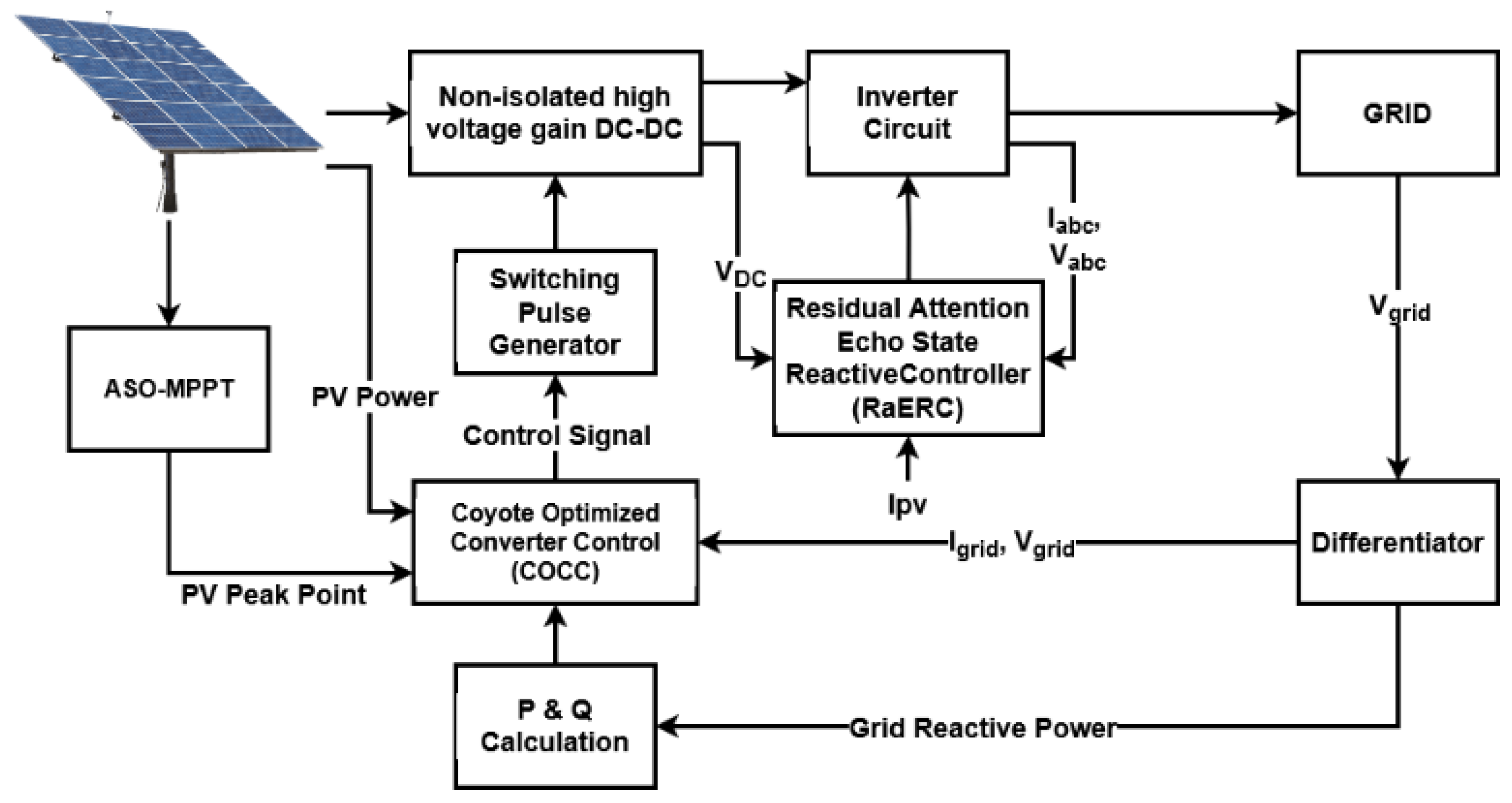
2. Proposed Methodology

This section provides the clear explanation for the proposed controlling techniques used for improving the capability of reactive power compensation in grid-PV systems. The original contribution of this work is to develop an optimization based controlling algorithms for increasing the power quality of grid systems with better reactive power compensation capability. Here, an atom search optimization (ASO) based MPPT controlling technique is implemented to extract the maximum power field from the PV panels under different climatic conditions. After that, a non-isolated high voltage gain DC-DC converter is used to regulate the output PV voltage, since the PV voltage is random and unregulated that affects the overall system performance. To increase the voltage gain of DC-DC converter, a novel controlling algorithm, named coyote optimized converter control (COCC) is developed in this work. Moreover, the overall power quality of the grid-PV system is highly improved with reactive power injection ability by using a Residual Attention echo state reactive controller (RaERC). It helps to improve the inverter controlling operations of the overall system. The working flow and schematic representation of the proposed COCC-RaERC controlling system are shown in Figure 1 and Figure 2, respectively. The different types of methodologies and algorithms implemented in the proposed framework are as follows:
  • An ATOM search optimization (ASO)-based MPPT controlling algorithm
  • Coyote optimized converter control (COCC)
  • Residual attention echo state reactive control (RaERC)

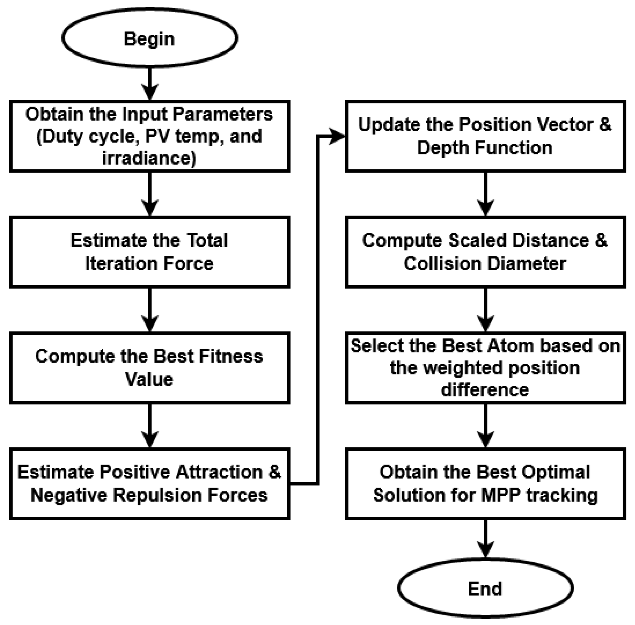
2.1. ASO Based MPPT Controlling

In this work, the maximum solar power is obtained from the PV panels by using an advanced ASO based MPPT controlling technique. In the existing works, different types of MPPT controllers have been used to obtain the maximum energy yield from the PV source under different climatic conditions. Among other controlling techniques, the optimization based MPPT models are widely used in the grid-PV applications, since they highly satisfy the energy demand according to the requirements of load. Moreover, the optimal solution provided by the optimization is used to identify the MPP for gaining the maximum energy. When compared to the existing optimization techniques, an ATOM search is one of the newest and most intelligent optimization algorithms, which efficiently solves the multi-objective problems with improved convergence rate. Moreover, it identifies the best optimal solution with reduced number of iterations. Typically, the AOS is a meta-heuristic optimization technique, which is developed based on the molecular dynamics. Figure 3 represents the work flow model of the ASO algorithm used for MPPT controlling.
In this technique, the duty cycle, PV cell temperature, and solar irradiance are initialized as the inputs, and the best optimal solution is produced as the output that helps to identify the MPP for power tracking. Initially, the total interaction force on jth atom at mth dimension is estimated by using the following equation:
I F j , m t = k   S atom rand k I F k , m t
where  rand k  is the random number in the range of 0 to 1, and  S atom  represents the subset of atom population. In order to increase the exploitation ability of optimization, each atom is required to interact with few atoms with best fitness vale of its  ȵ  neighbors as illustrated below:
ȵ t = N atom N atom 2 × t I t  
where  N atom  is the total number of atoms in the atomic system,  t  is the current iteration, and  I t  represents the maximum number of iterations. Here, the interaction force is considered as the gradient of Lennard-Jones (L-J) potential, and its revised version with positive attraction and negative repulsion forces are estimated by using the following equation:
I F jh , m t = ϑ t 2 × d j , h t 13 d j , h t 7 × p j , h p j , h
where  ϑ t  represents the depth function used for adjusting the repulsion or the attractive regions,  d j , h t  is the dynamic parameter  p j , h α t p j , h  is the position distance vector =  y j ˜ y h ˜ p j , h  denotes the position vector between  j th  atom and any random atom, and  α t  is the length scale. Then, the parameter  y j ˜ = y j 1 , y j 2 , y j 3  is the position vector of  j th  atom, and  y h ˜ = y h 1 , y h 2 , y h 3  is the position vector of  m th  atom. Moreover,  p j , h  is formulated by using the following model:
p j , h = y j ˜ y h ˜ = y j 1 y h 1 2 + y j 2 y h 2 2 + y j 3 y h 3 2
Consequently, the depth function is computed by using the following equation:
ϑ t = ρ   1 t 1 T   e 20 t T
where  ρ  represents the depth weight is equal to 50. Moreover, the scaled distance is computed between two atoms by using the following model:
d j , h t = D C   if   p j , h < p j , h α t D C R d × Δ D   if   0 < p j , h < p j , h α t D C + R d × Δ D   if   p j , h > p j , h α t  
Then, the relation between the PV voltage and duty cycle is estimated as shown below:
PV V = 1 d j , h × V
After that, the collision diameter is estimated according to the length scale  α t  as shown in below:
α t = || y jh t , k   S atom y kh t ȵ t ||
The resultant geometric constraint force is computed based on the weighted position difference between each atom and best atom by using the following model:
Ğ j m t = ƍ t y best m t y j m t
where  y best m t  indicates the position of the best atom in  m th  dimension,  ƍ t  is the Lagrangian multiplier =  ɀ e 20 t T , and  ɀ  is the multiplier weight = 0.2. Similarly, the acceleration of jth atom with dimension m at iteration t is computed by using the following equation:
A j m t = I F j , m t m s j , m t + Ğ j m t m s j , m t
ρ   1 t 1 T   e 20 t T ×   k   S atom r k 2 × d k , h t 13 d k , h t 7 m s k t   × y k m t y j m t y j ˜ y k ˜ 2 + ɀ e 20 t T   y best m t y j m t m s j t
where  m s j , m t  indicates the mass of atom j in the  m th  dimension at iteration  t , and is estimated by using the following model:
m s j t = e f j t f b t f w t f b t r = 1 N atom e f r t f b t f w t f b t
where  f j t  is the fitness function value of  j th  atom at iteration  t f b t  and  f w   t  are the fitness values of the best and worst atoms at iteration  t , respectively. Finally, the relation between the PV voltage and current is estimated as shown below:
I PV = S G S G N atom × I 1 N atom + PV T PV T N atom
I R = I 2 × exp A j m t   V + I 3 d f l c PV T 1
I D = V I 3 R 1
I S = I PV I R I D
where  A j m t  is electron charge,  I 1 N atom  short circuit current at standard test conditions,  G solar N atom  solar irradiance at standard test conditions,  I 2  saturation current,  I 3  current at the series resistance,  d f  ideal factor, and  l c  the Boltzmann constant.
R 1  denotes parallel resistance,  I PV  photo current,  I R  parallel resistance current, and  I D  diode current. Then, the PV power is obtained based on the optimal solution of voltage and current, as shown below:
PV P = PV V × I S
The following Algorithm 1 illustrates the steps involved in the ASO-MPPT controlling model.
Algorithm 1: ASO based MPPT Controlling.
Input: Initialize Duty cycle DC, cell temperature PVT, solar irradiance SG;
Output: Optimal solution;
Procedure:
Step 1: The total interaction forces acting  I F j , m t  on the jth atom in mth dimension as shown in Equation (1);
Step 2: To make algorithm more exploitation at final iteration, each atom needs to interact as few atoms with better fitness values as computed in Equation (2)
Step 3: The interaction force is the gradient of Lennard-Jones (L-J) potential, the revised version of this model with positive attraction and negative repulsion forces as represented in Equation (3)
Step 4: The depth function is computed by using Equation (5);
Step 5: The scaled distance is estimated between two atoms as shown in Equation (6);
Step 6: The relation between the solar panel voltage and duty cycle is estimated by using Equation (7);
Step 5: The length scale α(t) is estimated using Equation (8);
Step 6: The resulting geometric constraint force is computed using Equation (9);
Step 7: The acceleration of the jth atom in mth dimension at iteration t is calculated as represented in Equation (10);
Step 8: The relation between the PV current and voltage is estimated as shown in Equation (12);
Step 9: Finally, the optimal solution of voltage and current is estimated to obtain the power as represented in Equation (17);

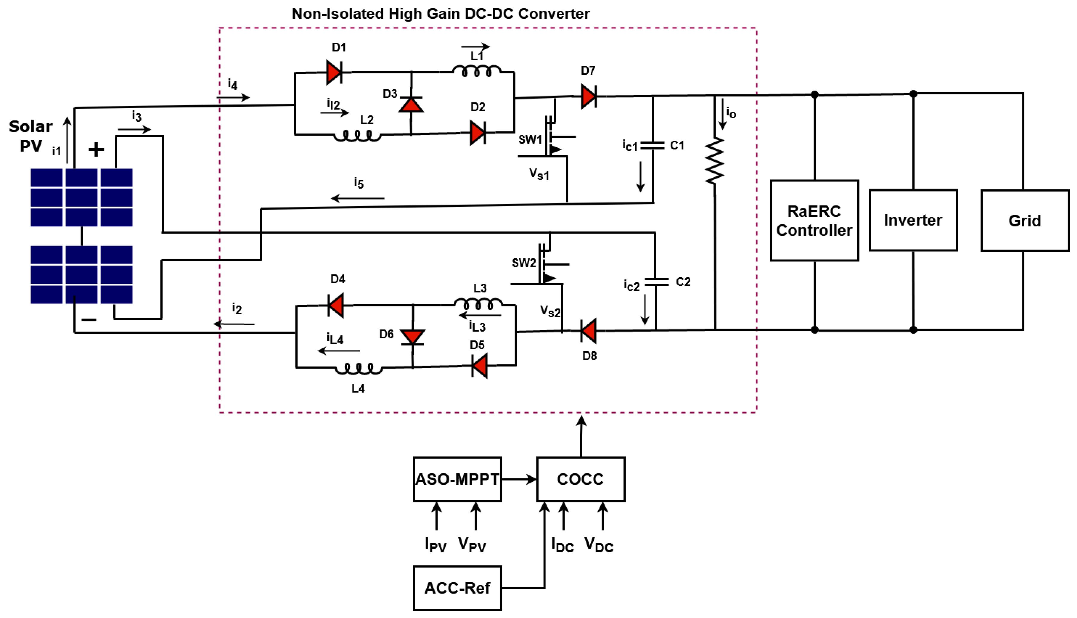
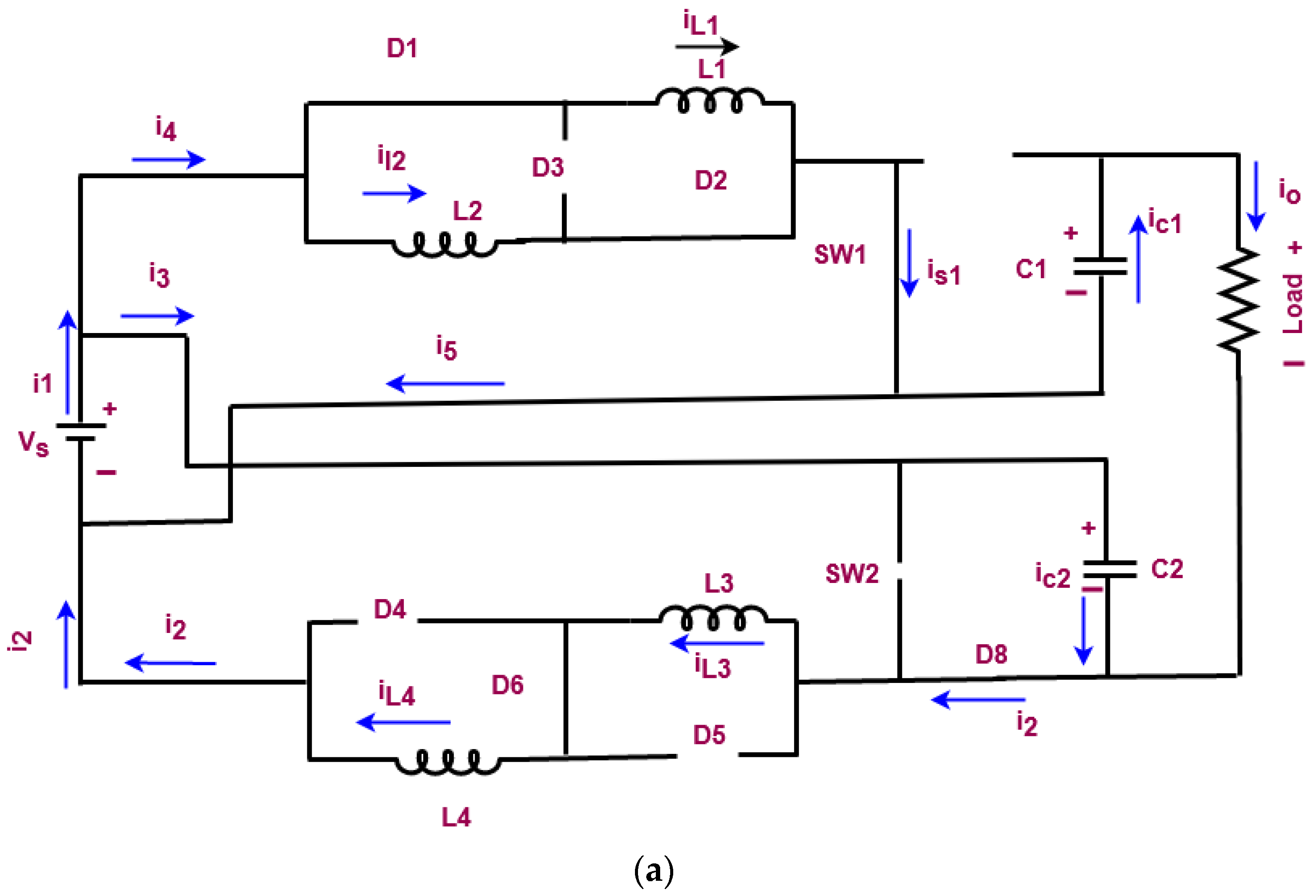
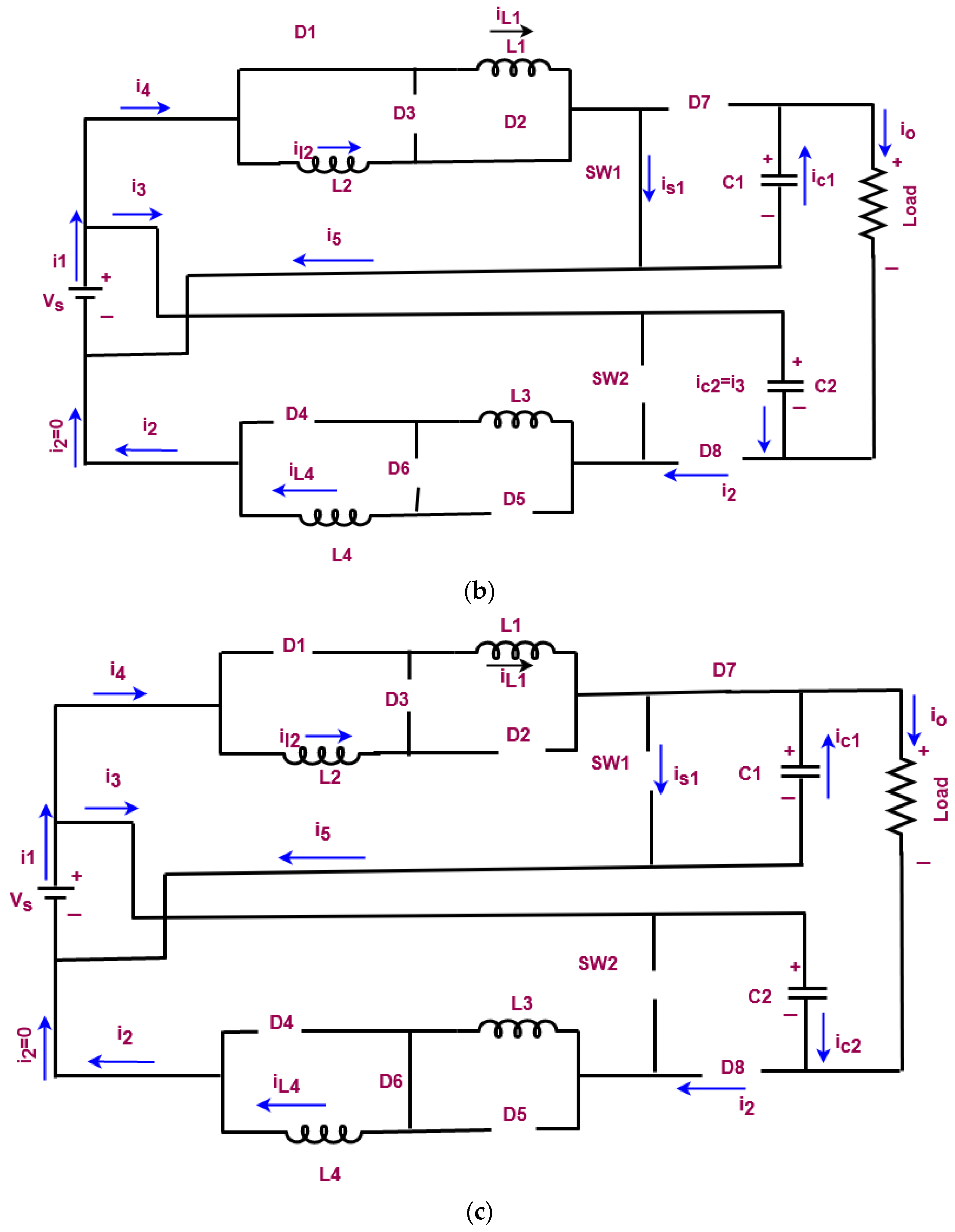
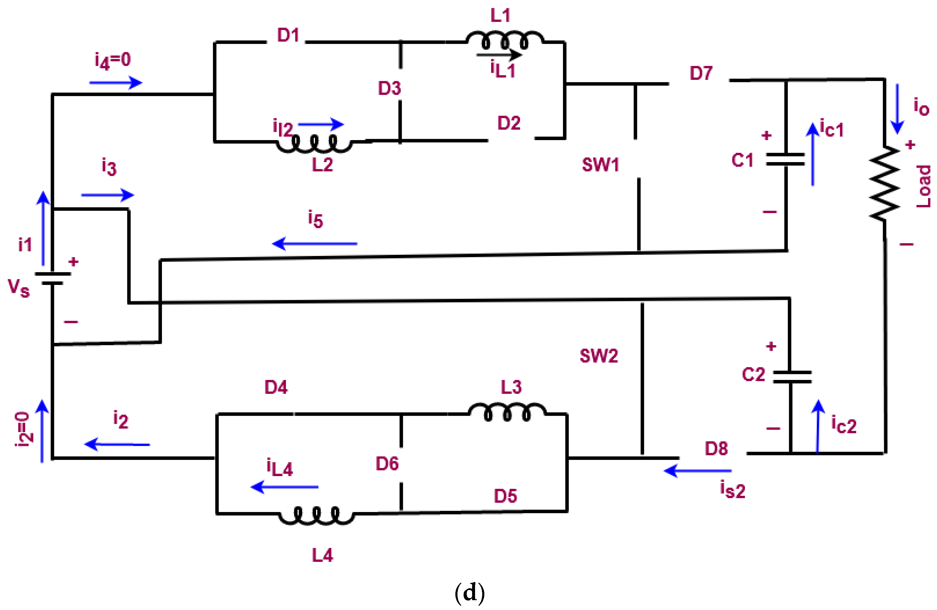
2.2. Non-Isolated High Voltage Gain DC-DC Converter

In this work, a non-isolated high voltage gain DC-DC converter has been used to properly regulate the output voltage of PV, because the PV output is naturally unregulated. It may disrupt the overall performance and efficiency of the grid system. Hence, it must be properly regulated and boosted for obtaining the maximum output voltage. Thus, the proposed work aims to utilize an advanced non-isolated high voltage gain DC-DC converter for voltage regulation and boosting. This type of converter is more suitable for large-scale applications since it highly improves the voltage with minimal loss factor. Moreover, it can operate with the reasonable duty cycle, and it incorporates the switched inductor structure with the dual boost topology. When compared to the other DC-DC converters, it has the key benefits of reduced switching stress, switching loss, high voltage gain, and efficiency. To improve the performance of converter, a novel COCC is implemented in this work, which generates the controlling pulses for operating the switching components of the converter. The circuit representation of the non-isolated high gain DC-DC converter is shown in Figure 4, and its modes of operation are represented in Figure 5a–d. During mode 1, the switch SW 1 is in on state, SW 2 is in off state, the diodes D1, D2, D6, and D8 are forward biased, and D3, D4, D5, and D7 are reverse biased. In mode 2, the switches are in the same state, but the diodes D1 and D2 are forward biased, and D3–D8 are reverse biased. During mode 3, both switches are in off state, diodes D1, D2, D4, and D5 are reverse biased, and D3, D6, D7, and D8 are forward biased. Finally, the switches SW 1 is in off state, and SW 2 is in on state during mode 4; diodes D4 and D5 are forward biased, while D1, D2, D3, D6, D7, and D8 are reverse biased.

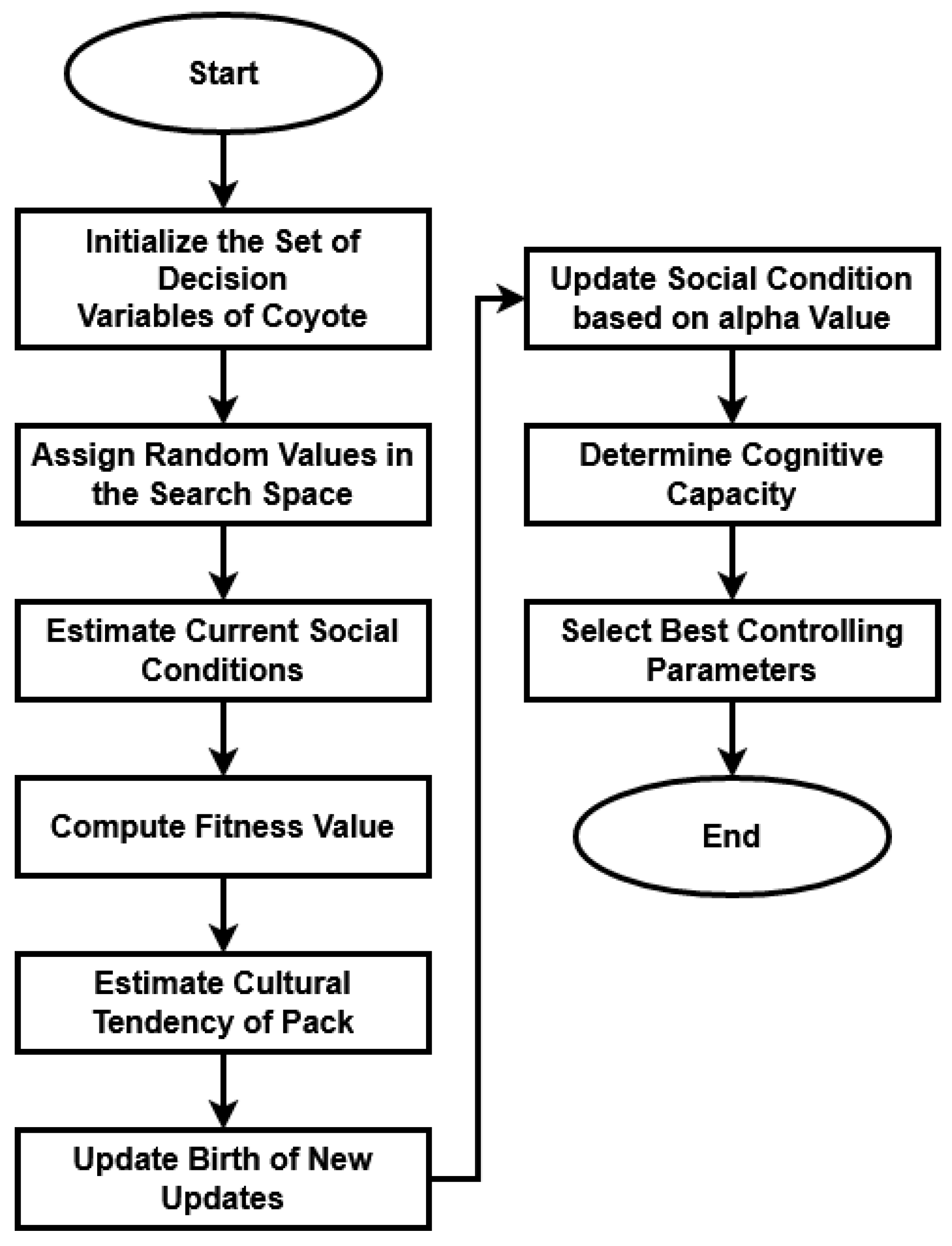
2.3. Coyote Optimized Converter Control (COCC)

The main purpose of implementing this controlling algorithm is to obtain an increased output voltage with reduced switching losses and frequency. The proposed COCC is developed based on the coyote optimization technique, which returns the best solution for the optimal selection of parameters  𝓀 p ,   𝓀 i , and  𝓀 d . This helps to generate the controlling pulses for operating the switching components of the DC-DC converter. In this controlling algorithm, the PV output voltage, error signal, and sampling time are taken as the inputs, and the optimal selection of parameters is produced as the output. Figure 6 shows the working flow of the CO algorithm.
The coyote optimization algorithm is a population-based algorithm that simulates the path that coyotes take in their adaption to their surroundings and social activities. In the course of its operation, it combines swarm intelligence with natural heuristics. Moreover, it provides a balance between exploration and creation for optimization procedures. Specifically, this optimization technique has the major benefits of high convergence rate, high processing speed, and low computational complexity. In this technique, finding the optimal solution in the searching space consumes low time with minimal iterations. Therefore, the computational burden of the COCC is effectively reduced, and it is more reliable in nature. Hence, the proposed COCC performs better than the conventional algorithms. Initially, the set of decision variables of coyote are initialized based on the following model:
S C t y c , p k = z ^ = z 1 , z 2 ,   ,   z T sp
where  S C  is the social condition of the  y c th  coyote, and  p k th  is the pack at time of instant t. Then, the random values are assigned inside the searching space for the coyote with dimension k, and is estimated as follows:
S C t y c , p k k = V n k + rand 0 , 1 × V n k V o k   k = 0 , 1 , 2 , , n
where  V n  indicates the maximum voltage,  V o  is the initial voltage, and  k th  indicates the decision variable. The coyotes’ adaptation in the respective current social conditions are evaluated by using the following models:
fit t y c , p k = fun S C t y c , p k
where  fit t y c , p k  indicates the fitness value of the  y c th  coyote of the  p k th  pack at instant of time t, and  fun .  is the objective function. Here, the minimization problem is considered, in which the alpha value of  y c th  coyote of the  p k th  pack at  t th  instant time is computed by using the following model:
α t y c , p k = { S C t y c , p k   |   argmin y c = 1 , 2 , ,   N y fun S C t y c , p k }
where  N y  indicates the number of coyote population. Then, the cultural tendency of the pack is computed using the following model:
t y c , p k k = R N y + 1 2 ,   k t y c , p k   ,   N y = odd R N y 2 ,   k t + R N y + 1 2 ,   k t y c , p k 2 ,   Otherwise
where  R t y c , p k  represents the ranked social conditions of all coyotes of the  p k th  pack at time  t  for every  k  in the range [1,  T sp ]. Consequently, the birth of new coyotes is updated based on the combination of the social conditions with two parents, as shown below:
ψ t y c , p k k = S C t y c , p k r 1 , k   e sig < S pr S C t y c , p k r 2 , k   e sig S pr rand k   else + A pr  
where  r 1  and  r 2  are the random coyotes from the  r 1  pack,  S pr  is the scatter probability,  A pr  is the association probability,  rand k  is a random number inside the decision variable bound of the  k th  dimension and  e sig  is a error signal. Moreover, the new social condition is updated by using the alpha value with the following condition:
NewS C t y c , p k = S C t y c , p k + r 1 × φ 1 + r 2 × φ 2
where  NewS C t y c , p k  indicates the coyote’s new social condition,  φ 1  is the alpha influence, and  φ 2  is the pack influence, which are estimated as follows:
φ 1 = α t y c , p k S C t y c , p k
φ 2 = t y c , p k S C t y c , p k
The coyote’s cognitive capacity is determined. If the new social condition is better than the older one, then it kept, as illustrated using the following equation:
S C t + 1 y c , p k = NewS C t y c , p k   Nfit t y c , p k < fit t y c , p k S C t y c , p k   otherwise
where  Nfit t y c , p k = fun NewS C t y c , p k  indicates the fitness value for a new population. Based on this process, the best controlling parameters are selected by using the following equations:
𝓀 p = Nfit t y c , p k L
𝓀 i = 𝓀 p × 2 × L
𝓀 d = 𝓀 p × Nfit t y c , p k
By using these controlling parameters, the controlling pulses are generated to operate the switching devices, which helps to highly improve the output voltage of PV. Algorithm 2 illustrates the steps involved in the COCC model.
Algorithm 2: Coyote Optimized Converter Control (COCC).
Input: Output Voltage PVV, error signal Es and sampling time Tsp;
Output: Optimal selection of parameters;
Step 1: The social condition SC (set of decision variables) of the  y c th  coyote of the  p k th  pack in the t th instant of time is computed by using Equation (18);
Sampling Time is estimated by Ts = 1/Fs//Fs − switching frequency
Step 2: The random value is assigned inside the searching space for the  y c th  coyote of the  p k th  pack in kth dimension by using Equation (19);
Step 3: After that, the coyotes’ adaptation in the respective current social conditions are evaluated by using Equation (20);
Step 4: The minimization problem is considered in this model, where the alpha of the  y c th  coyote of the  p k th  pack in the tth instant of time is estimated by using Equation (21);
Step 5: The cultural tendency of the pack is computed based on Equation (22);
Step 6: The birth of a new coyotes is updated based on the combination of the social conditions of two parents (randomly chosen) as shown in Equation (23);
Step 7: The coyote’s new social condition is updated with the alpha pack influence through Equations (24)–(26);
Step 8: The coyote’s cognitive capacity decide if the new social condition is better than the older one to keep it, which is represented in Equation (27);
Step 9: Finally, the best controlling parameters kp, ki, kd are selected based on the Equations (28)–(30);

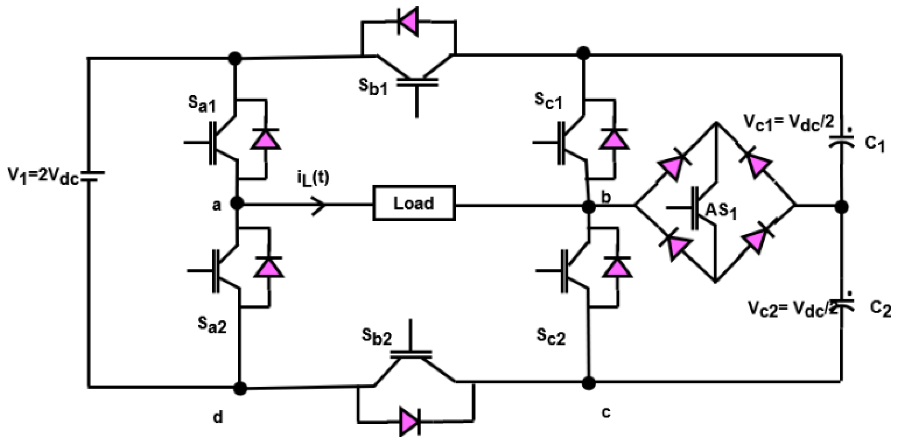
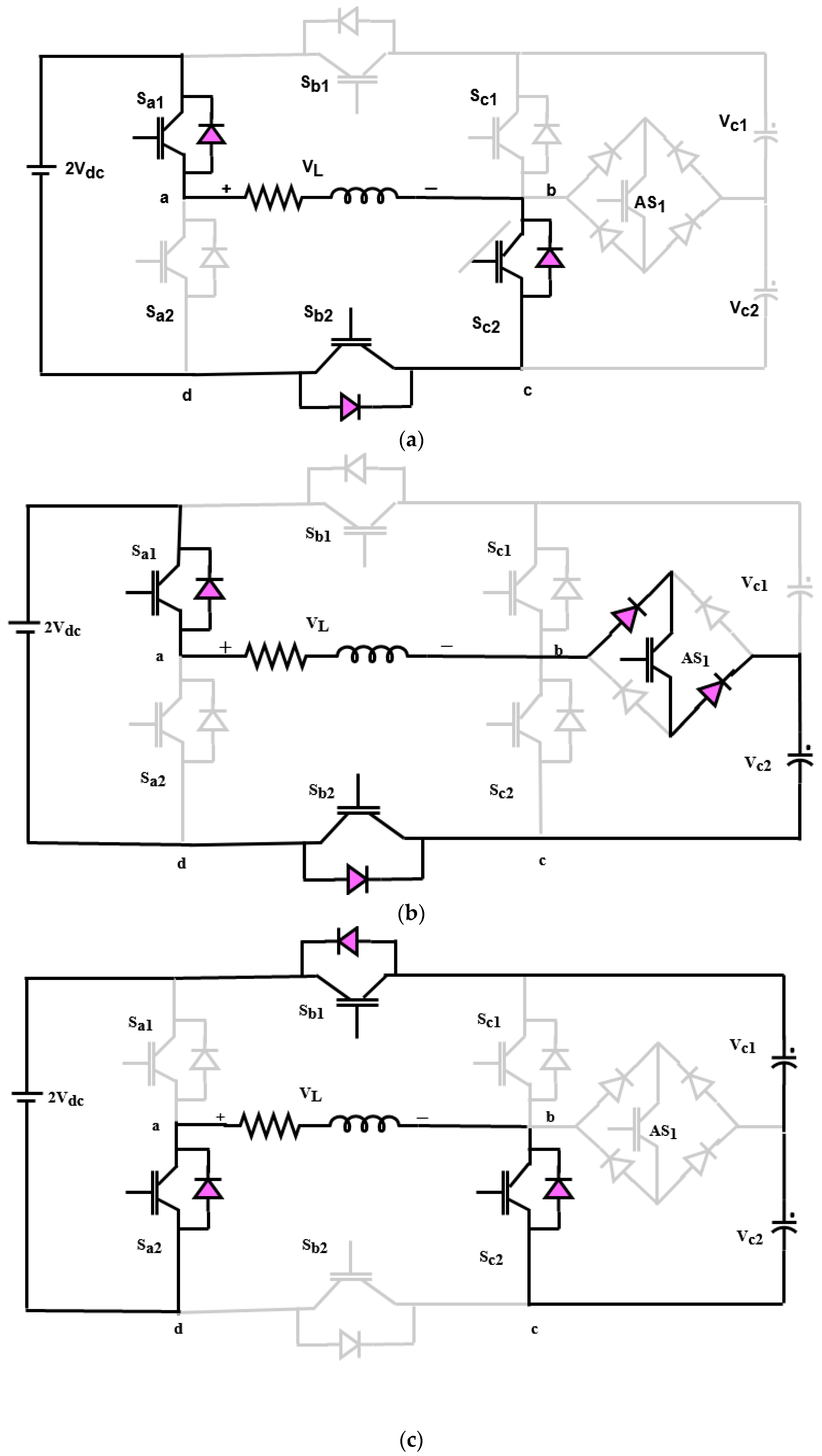
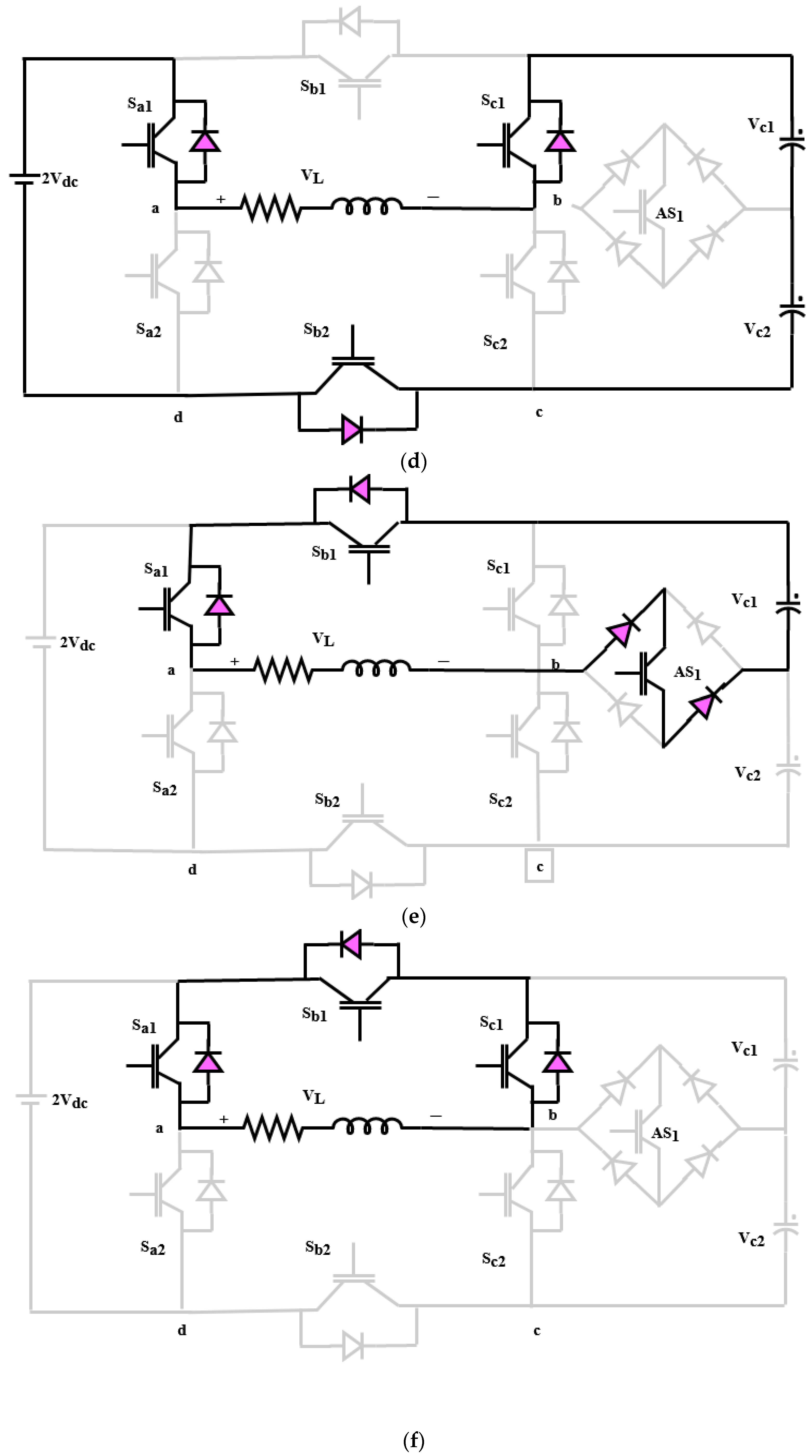
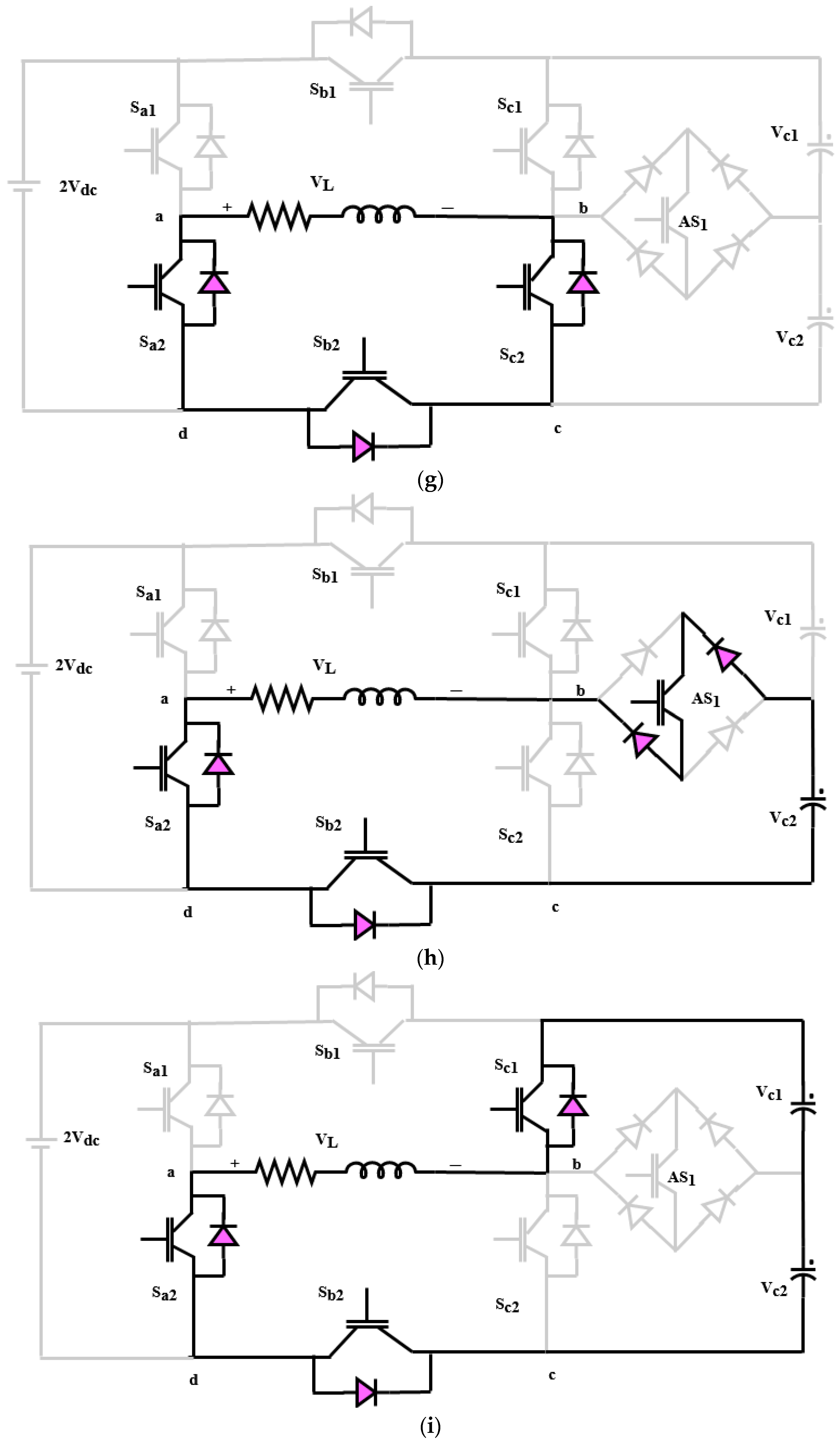
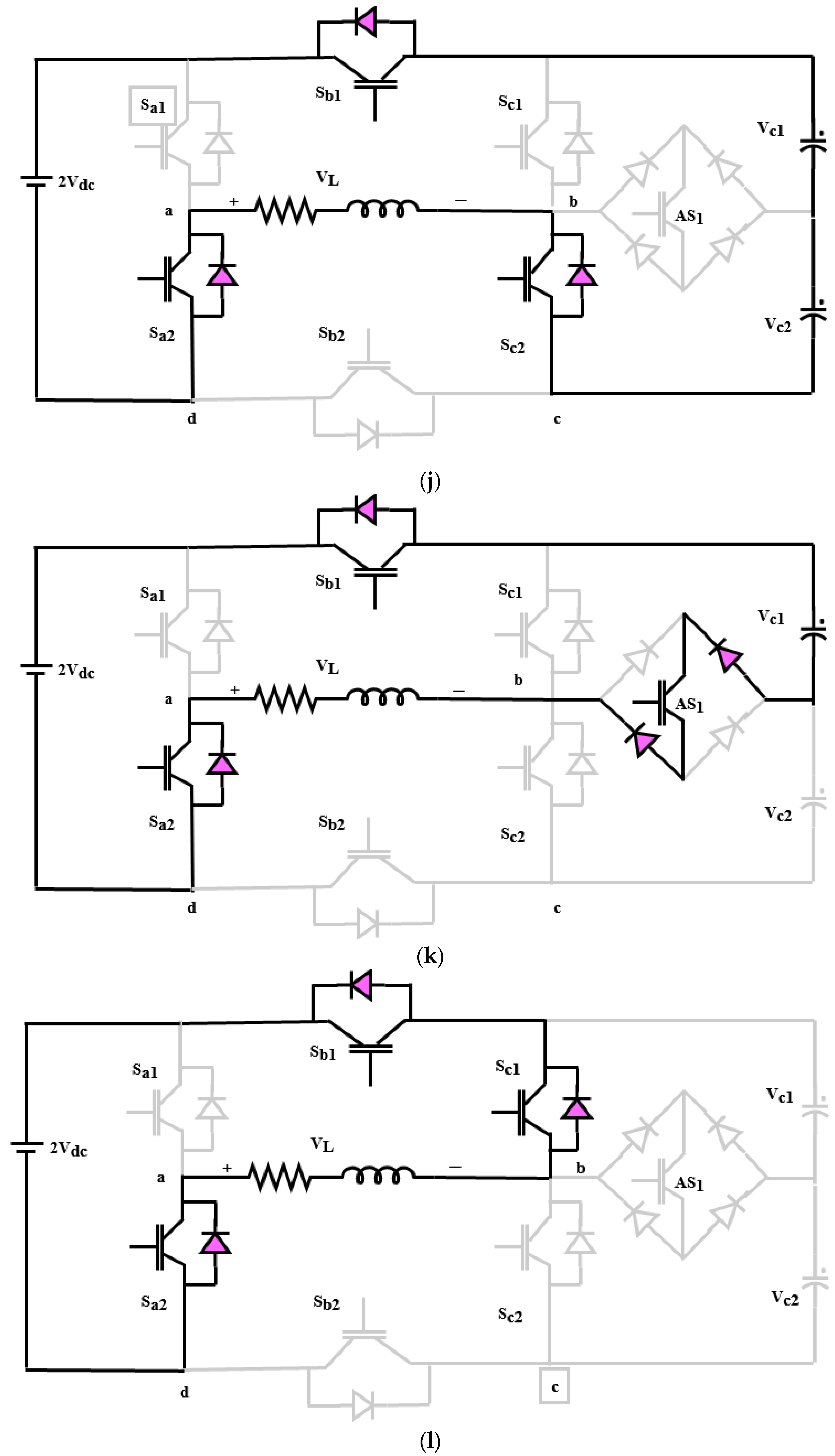
2.4. Nine-Level Inverter

In this work, the nine-level inverter topology has been utilized to improve the power quality of the grid-PV systems with the reactive power injection capability. Here, a new structure of multilevel inverter has been utilized that efficiently reduces the presence of harmonics for increasing the quality of output power. One of the primary advantages of using this inverter is that it requires only a single gate driver circuitry, where the collector and emitter are bi-directionally configured. The proposed MLI structure demonstrated in this work can generate nine levels using just one DC supply and seven power electronic components (six unidirectional and one bidirectional). One insulated gate bipolar transistor (IGBT), four diodes, and one chip make up the bidirectional device used in this layout. This device has one major advantage over conventional bidirectional devices: it only needs one gate driver circuitry, as opposed to the two drivers required by bidirectional devices based on the common collector and common emitter arrangement. Additionally, the physical dimensions of the bidirectional device with a single chip packed are practically identical to those of the unidirectional device with the same ratings. As a result, a single chip packed bidirectional device requires less room to implement and is smaller than an inverter.
The equivalent circuit model of the proposed nine-level inverter topology is shown in Figure 7, and its modes of operation are illustrated in Figure 8a–d. Moreover, the switching states with charging C, discharging DC, and no effect NE models are illustrated in Table 1. As shown in this model, the switches Sb1 and Sb2 are complementary to the switches Sa1 and Sa2 in all states of switching. In most of the states, the switches Sc1 and Sc2 are complementary to each other, excluding the states of S2, S5, S8, and S11. So, consider the switches Sai, Sbi, Sci (i.e., i = 1, 2), and their switching functions AS1 are computed by using the following equations:
S ai = 1 if   S ai   is   on 0 if   S ai   is   off ,   i ,   1 , 2
S bi = 1 if   S bi   is   on 0 if   S bi   is   off ,   i ,   1 , 2
S ci = 1 if   S ci   is   on 0 if   S ci   is   off ,   i ,   1 , 2
AS 1 = 1 if   AS 1   is   on 0 if   AS 1   is   off ,   i ,   1 , 2
Consequently, the output inverter voltage is computed by using the following model:
V ab = V ad + V dc + V ce + V eb
V dc = 1 S a 2 V 1
V ce = V C 2
V eb = 1 AS 1 S c 2 V C 2 S c 1 V C 1
V ab = S b 2 S a 2 V 1 S b 2 + S c 1 1 V C 1 S b 2 S c 2 V C 2

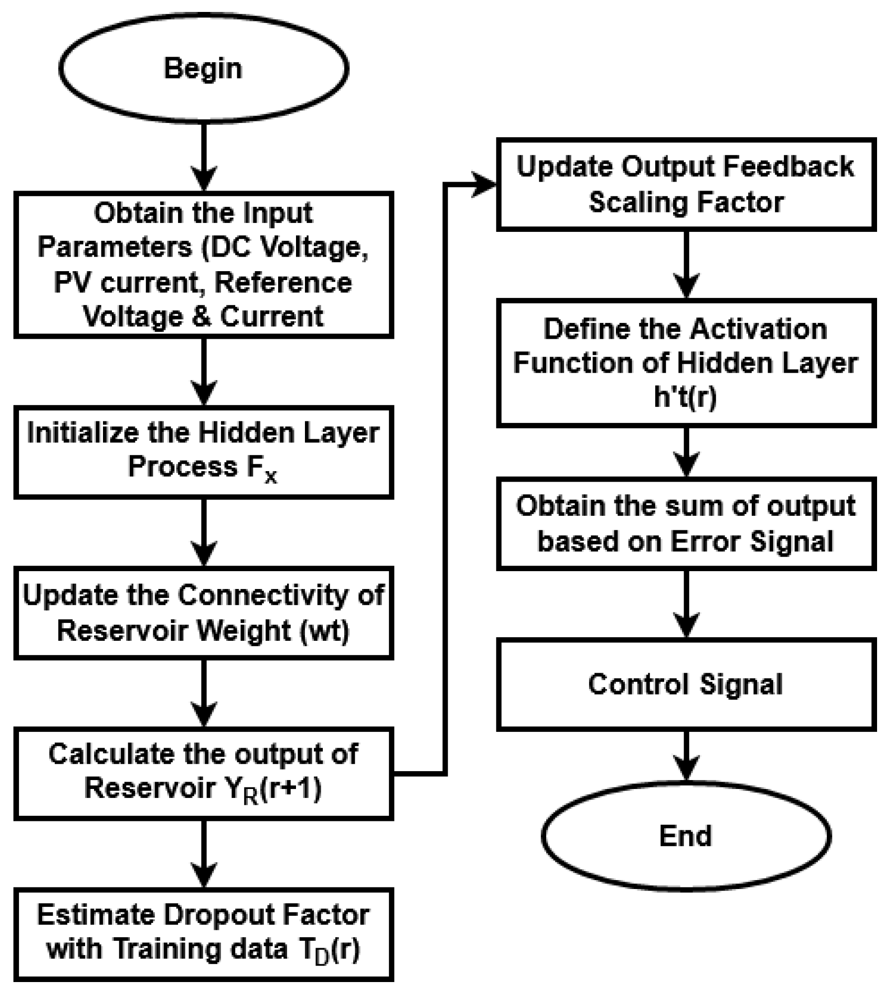
2.5. Hybrid Residual Attention Echo State Reactive Controller (RaERC)

The hybrid RaERC controlling technique is mainly developed for improving the performance of inverter by reducing the harmonics with better reactive power compensation capability. The main contribution of the proposed work is to develop a computationally efficient reactive power compensation system for grid-PV systems. For this purpose, a nine-level inverter topology has been utilized in this work, which improves the capability of reactive power injection with increased power quality. The controlling signals allowed to operate the switching components of the nine-level inverter has been generated by using the proposed RaERC. This technique helps to reduce the harmonic contents with increased power quality outputs, and further supports to improve the capability of reactive power support. This technique considers the input of output PV voltage, current, reference voltage and current, and produces the control signal as the output. Initially, the hidden layer process is initialized by using the following models:
F x = V D C , I P V , V R e f , I R e f
F x r + 1 = f t w t j s i r + w t e F x r
where  F x r + 1  &  F x r  are the feature matrix of voltage and current and  r t h  and  r + 1 t h  rounds,  w t j  represents the reservoir matrix with weight values from feature matrix,  w t r  indicates the reservoir matrix with internal states,  s i r + 1  is the state matrix harvested internally, and  f t .  denotes reservoir activation function. After that, the connectivity of reservoir weight is updated according to the weight matrix, as shown below:
w t t + 1 = 1 + G j r × F x j r
where  j  indicates the feature matrix indices,  G j r  denotes the feature gradient matrix at   r t h  round, and  w t j r + 1  represents the updated weight matrix at the  r t h  round. Then, the output of reservoir is calculated as follows:
Y R r + 1 = h t w t o F x j r + 1
where  w t o  represents the weight matrix from output neuron, and  h t .  indicates the evaluated reservoir decision making function. Moreover, the dropout factor is estimated by using the following model:
T D r = 1 2   n r = 1 n δ ×   w t j ×   Y R r
where  δ  indicates the dropout factor,  w r  represents the weight value of the  r t h  target vector,  T D t  is the train data with D dimension, and  n  is the number of neurons. After that, the output feedback scaling factor is updated with the forward pass by using the following equation:
c t = T D t a t + h t f c u r r e n t t
where  c t  indicates the feedback signal,  a t  represents the combination of feedback and feature map, and  h t  is the activation function for feedback mechanism. Moreover, the activation function of the hidden layer is defined based on the following model:
h t r = 1 1 + e x p B n r
where  n  is the number of neurons and  B n  indicates the bias value = weighting sum total at the  n t h  neuron, calculated as follows:
B n = r = 1 n w r Y R r
Then, the sum of output is estimated according to the error signal, as shown below:
Φ = 1 2 d = 1 N P d T d
P r = c t T e D
T e D = t e s t d a t a V D C , I P V , V R e f , I R e f
where  P r  is the output actual value and  N  is the total number of neurons. Based on the output value, the controlling parameter that helps to generate the switching pulses for operating switching devices of the inverter is generated. This efficiently reduces the harmonic distortions with increased output power fed to the grid system. Figure 9 shows the work flow model of RaERC algorithm used for reactive controlling. Algorithm 3 illustrates the steps involved in the RaERC model.
Algorithm 3: Residual Attention Echo State Reactive Controller (RaERC).
Input: DC voltage VDC, PV current IPV, reference voltage VRef and reference current IRef;
Output: Control signal;
Procedure:
Step 1: The dynamic echo state hidden network process is performed by using Equations (40) and (41);
Step 2: Then, the connectivity of reservoir weight is formulated with respect to weight matrix as shown in Equation (42);
Step 3: The output of reservoir is estimated by using Equation (43):
Step 4: Estimate the dropout factor by randomly selecting the neurons for training by using Equation (44);
Step 5: Output feedback scaling is updated with forward pass as shown in Equation (45);
Step 6: Define the activation function for the hidden layer by using Equation (46);
Step 7: The squares’ sum of output is called as the error signal, which is estimated by using Equation (47);
Step 8: Return the control signal parameter as the output Pd;

3. Results and Discussion

This section presents the simulation and comparative analysis of the proposed controlling techniques used for improving the power quality and reactive compensation capability of the grid-PV systems. To examine the results of MPPT controlling, converter, and inverter topologies, the MATLAB/SIMULNK tool was used in this work. The novel contribution of this work is to implement advanced controlling mechanisms for resolving the power quality problems in the grid-PV systems. Here, the ASO based MPPT controlling mechanism is used to obtain the maximum energy yield from the PV panels. Figure 10a,b validates the IV and PV characteristics of the proposed ASO-MPPT mechanism with respect to varying temperature and irradiation conditions. Typically, the IV and PV characteristics are mainly estimated to analyze the power tracking efficiency of the MPPT controller. According to the results, it is analyzed that the proposed ASO-MPPT controller obtains the maximum possible energy yield from the PV panels by accurately identifying the MPP. Then, Figure 11 estimates the output power of PV with and without MPPT controlling techniques, where the results are estimated with respect to varying time instances. The estimated results indicate that the output power with MPPT is highly improved, when compared to the output without MPPT. Due to the proper tracking of MPP using an ASO algorithm, increased output power is obtained from the PV panels.
Figure 12 shows the output DC voltage of converter with respect to varying time instant in terms of seconds. The, the output power fed to the grid system is shown in Figure 13. By using a non-isolated high voltage gain DC-DC converter, the output of PV is highly improved and boosted with reduced switching frequency. This also helps to feed increased output power to the grid systems.
The obtained switching signals of the nine-level inverter topology used in this work is shown in Figure 14. The results depict that the switches Sa1 and Sa2 are operated under the fundamental frequency of the reference wave. Consequently, the switches Sb1, Sb2, Sc1, Sc2, and AS1 are operated at the frequency of the carrier wave. Moreover, the switching losses are efficiently reduced by using this inverter design, because the high voltage switching components are operated at the fundamental frequency and the low voltage switching devices are operated at higher frequency.
Similarly, Figure 15 shows the grid voltage waveform of the inverter with its associated harmonics spectrum. Moreover, the grid current and its harmonics spectrum are shown in Figure 16, where the dynamics of the inverter is validated with respect to varying step variations in the input voltage and load.
Figure 17 depicts the output grid voltage and current with respect to varying time in terms of seconds. Using the combination of CCOC-RaERC controlling techniques, the output voltage and current of grid systems are highly improved with reduced loss factor. Similarly, the reference and actual grid current of the proposed framework are validated and depicted in Figure 18.
Figure 19 presents the waveform analysis of the nine-level inverter with respect to grid voltage and current with the fall and change of values. Based on the results, it is observed that the current injected into the grid is in phase with the voltage. Similarly, the dynamic performance of the nine-level inverter topology is validated, as shown in Figure 20. In this analysis, the dynamic voltage, load current, and capacitor voltage have been computed for analyzing the dynamic variations. According to the results, it is observed that the proposed COCC-RaERC controlling model highly improves the performance of entire grid-PV system with increased power quality and reactive power compensation capability.
Figure 21 and Figure 22 compare the standard and proposed MPPT controlling techniques based on the parameters of overshoot, settling time, rise time, tracking time, and efficiency. Typically, the rise time, settling time, and overshoot must be reduced for ensuring improved MPPT tracking efficiency. Due to the improved convergence rate and speed of processing, the performance of the proposed ASO-MPPT technique is highly improved when compared to the other models. Consequently, qualitative comparative analysis among the standard and proposed MPPT models is presented in Table 2. This analysis also indicates that the proposed ASO-MPPT model outperforms the other controlling techniques with improved efficiency and accuracy.
Figure 23 and Figure 24 compare the THD, steady state oscillations and rise time of the conventional [47,48] and proposed optimization based controlling techniques used in the grid-PV systems. The estimated results state that the value of THD is effectively reduced in the proposed system when compared to the other controlling techniques. Similarly, the steady state oscillations and rise time are also effectively reduced in the proposed system.

4. Conclusions

This paper presents new controlling techniques for improving the capability of reactive power compensation with reduced harmonics in grid-PV systems. Here, the ASO based MPPT controlling technique is mainly used to obtain the maximum solar energy from the PV panels under varying climatic conditions. The purpose of using the ASO technique is identify the MPP based on the best optimal solution. Then, a non-isolated high voltage gain DC-DC converter is used to regulate the output PV voltage. For improving the performance of converter, a novel COCC mechanism is developed in this work, which provides the optimal selection of best controlling parameters to generate the switching pulses. Moreover, the nine-level inverter is used in this work to improve the power quality. In addition, the RaERC algorithm is developed to generate the controlling signals for operating the switching components of the nine-level inverter. This technique helps to reduce the harmonic contents with increased power quality outputs, and further supports an improvement in the capability of reactive power support. During analysis, the simulation results of the proposed controlling mechanisms are tested and validated based on different parameters. Among the other optimization based MPPT controlling techniques, e.g., bee colony, Firefly, jelly fish, horse herd, fruit fly, etc., the ASO-MPPT has demonstrated increased tracking efficiency with increased energy yield. Moreover, the output voltage of converter is highly boosted in the proposed framework when compared to the standard converters, such as bi-directional, boost, and flyback. Finally, the obtained results indicate that the proposed COCC-RaERC mechanism provides improved performance in terms of high voltage profile, reduced harmonics, and improved power quality.

Author Contributions

Conceptualization, R.M.S., S.R.S. and S.M.; methodology, G.D., S.R.S. and R.M.S.; software, R.M.S., S.M., G.D. and S.R.S.; validation, G.D., R.M.S. and S.R.S.; formal analysis, S.R.S., G.D. and S.M.; investigation, S.M. and S.R.S.; resources, S.M., G.D. and S.R.S.; data curation, R.M.S. and S.M.; writing—original draft preparation, S.M., S.R.S. and G.D.; writing—review and editing, R.M.S., S.M., G.D. and S.R.S.; visualization, R.M.S. and S.M; supervision, G.D. and S.R.S.; project administration, R.M.S., G.D. and S.R.S.; funding acquisition, S.M., G.D., S.R.S. and R.M.S. All authors have read and agreed to the published version of the manuscript.

Funding

This research received no external funding.

Institutional Review Board Statement

Not applicable.

Informed Consent Statement

Not applicable.

Data Availability Statement

Not applicable.

Conflicts of Interest

The authors declare no conflict of interest.

Nomenclature

SymbolDescription
  I F j , m Total interaction force
  rand k Random number [0 to 1]
  S atom Subset of atom population
  N atom Total number of atoms in the atomic system
  t Current iteration
  I t Maximum number of iterations
  ϑ t Depth function
  d j , h t Dynamic parameter
  p j , h Position distance
  j Atom
  α t Length scale
  ρ Depth weight
  y best m t Position of best atom
  ƍ t Lagrangian multiplier
  ɀ Multiplier weight
  m s j , m t Mass of atom
  t Iteration
  A j m t Electron charge
  I 1 N atom Short circuit current
  G solar N atom Solar irradiance at standard test conditions
  I 2 Saturation current
  I 3 Diode current
  d f Ideal factor
  l c Boltzmann constant
  R 1 Parallel resistance
  I D Diode current

References

  1. Eluri, H.; Naik, M.G. Energy Management System and Enhancement of Power Quality with Grid Integrated Micro-Grid using Fuzzy Logic Controller. IJEER 2022, 10, 256–263. [Google Scholar] [CrossRef]
  2. Nair, D.R.; Nair, M.G.; Thakur, T. A Smart Microgrid System with Artificial Intelligence for Power-Sharing and Power Quality Improvement. Energies 2022, 15, 5409. [Google Scholar] [CrossRef]
  3. Nagadurga, T.; Narasimham, P.; Vakula, V.; Devarapalli, R. Gray wolf optimization-based optimal grid connected solar photovoltaic system with enhanced power quality features. Concurr. Comput. Pract. Exp. 2022, 34, e6696. [Google Scholar] [CrossRef]
  4. Tercan, S.M.; Demirci, A.; Gokalp, E.; Cali, U. Maximizing self-consumption rates and power quality towards two-stage evaluation for solar energy and shared energy storage empowered microgrids. J. Energy Storage 2022, 51, 104561. [Google Scholar] [CrossRef]
  5. Paramasivam, S.K.; Ramu, S.K.; Mani, S.; Muthusamy, S.; Sundararajan, S.C.M.; Panchal, H.; Sadasivuni, K.k. Solar photovoltaic based dynamic voltage restorer with DC-DC boost converter for mitigating power quality issues in single phase grid. Energy Sources Part A Recovery Util. Environ. Eff. 2022, 44, 91–115. [Google Scholar] [CrossRef]
  6. Andela, M.; Shaik, A.; Beemagoni, S.; Kurimilla, V.; Veramalla, R.; Kodakkal, A.; Salkuti, S.R. Solar photovoltaic system-based reduced switch multilevel inverter for improved power quality. Clean Technol. 2022, 4, 1–13. [Google Scholar] [CrossRef]
  7. Kumar, R. Fuzzy particle swarm optimization control algorithm implementation in photovoltaic integrated shunt active power filter for power quality improvement using hardware-in-the-loop. Sustain. Energy Technol. Assess. 2022, 50, 101820. [Google Scholar] [CrossRef]
  8. Salem, W.; Gabr Ibrahim, W.; Abdelsadek, A.M.; Nafeh, A. Grid connected photovoltaic system impression on power quality of low voltage distribution system. Cogent Eng. 2022, 9, 2044576. [Google Scholar] [CrossRef]
  9. Gupta, A. Power quality evaluation of photovoltaic grid interfaced cascaded H-bridge nine-level multilevel inverter systems using D-STATCOM and UPQC. Energy 2022, 238, 121707. [Google Scholar] [CrossRef]
  10. Das, B.; Panigrahi, P.K.; Das, S.R.; Mishra, D.P.; Salkuti, S.R. Power quality improvement in a photovoltaic based microgrid integrated network using multilevel inverter. Int. J. Emerg. Electr. Power Syst. 2022, 23, 197–209. [Google Scholar] [CrossRef]
  11. Alqarni, Z.A. Design of Active Fault-Tolerant Control System for Multilevel Inverters to Achieve Greater Reliability With Improved Power Quality. IEEE Access 2022, 10, 77791–77801. [Google Scholar] [CrossRef]
  12. Ahmad, S.; Iqbal, A.; Ashraf, I.; Meraj, M. Improved power quality operation of symmetrical and asymmetrical multilevel inverter using invasive weed optimization technique. Energy Rep. 2022, 8, 3323–3336. [Google Scholar] [CrossRef]
  13. Bughneda, A.; Salem, M.; Richelli, A.; Ishak, D.; Alatai, S. Review of multilevel inverters for PV energy system applications. Energies 2021, 14, 1585. [Google Scholar] [CrossRef]
  14. Kulkarni, J.; Yadav, S.K.; Singh, B.; Kumar, N. Power quality investigation of CHB nine-level converter based large-scale solar PV system with different modulation schemes. Energy Convers. Econ. 2021, 2, 145–156. [Google Scholar] [CrossRef]
  15. Upreti, S.; Yadav, S.K.; Singh, B.; Kumar, N. New Multicarrier Modulation Scheme for Harmonics Mitigation of T-Type Solar Multilevel Inverter. J. Inst. Eng. Ser. B 2022, 103, 903–911. [Google Scholar] [CrossRef]
  16. Maheswari, K.; Bharanikumar, R.; Arjun, V.; Amrish, R.; Bhuvanesh, M. A comprehensive review on cascaded H-bridge multilevel inverter for medium voltage high power applications. Mater. Today Proc. 2021, 45, 2666–2670. [Google Scholar] [CrossRef]
  17. Yadav, S.K.; Mishra, N.; Singh, B. Optimal third harmonic injection based nearest level control of large-scale solar photovoltaic multilevel converter. Energy Convers. Econ. 2022, 3, 61–71. [Google Scholar] [CrossRef]
  18. Vanaja, D.S.; Stonier, A.A.; Mani, G.; Murugesan, S. Investigation and validation of solar photovoltaic-fed modular multilevel inverter for marine water-pumping applications. Electr. Eng. 2022, 104, 1163–1178. [Google Scholar] [CrossRef]
  19. Srinivasan, S.; Muthubalaji, S.; Devadasu, G.; Anand, R. Bat algorithm based selective harmonic elimination PWM for an eleven level inverter. Int. J. Recent Technol. Eng. 2019, 8, 1164–1169. [Google Scholar]
  20. Patra, B.; Nema, P. Analysis of Solar Integrated Multilevel Inverter for Smart Grid Power Filters. In Proceedings of the 2021 International Conference on Advances in Electrical, Computing, Communication and Sustainable Technologies (ICAECT), Bhilai, India, 19–20 February 2021; pp. 1–5. [Google Scholar]
  21. Yadav, S.K.; Mishra, N.; Singh, B. Multilevel Converter with Nearest Level Control for Integrating Solar Photovoltaic System. IEEE Trans. Ind. Appl. 2022, 58, 5117–5126. [Google Scholar] [CrossRef]
  22. Upreti, S.; Singh, B.; Kumar, N. Harmonics Minimization in PUC Type Solar Multilevel Converter with Multicarrier Switching Schemes. IETE J. Res. 2022, 1–10. [Google Scholar] [CrossRef]
  23. Sidhartha, P.; Muthubalaji, S.; Devadas, G. Fuzzy Pi Controller Based Single Phase Hybrid Inverter for Domestic Applications. Int. J. Eng. Adv. Technol. (IJEAT) ISSN 2019, 9, 2249–8958. [Google Scholar] [CrossRef]
  24. Shunmugham Vanaja, D.; Stonier, A.A.; Moghassemi, A. A novel control topology for grid-integration with modular multilevel inverter. Int. Trans. Electr. Energy Syst. 2021, 31, e13135. [Google Scholar] [CrossRef]
  25. Tariq, M.; Zaheer, H.; Mahmood, T. Modeling and Analysis of STATCOM for Renewable Energy Farm to Improve Power Quality and Reactive Power Compensation. Eng. Proc. 2021, 12, 44. [Google Scholar]
  26. Jamil, H.; Qayyum, F.; Iqbal, N.; Kim, D.-H. Enhanced Harmonics Reactive Power Control Strategy Based on Multilevel Inverter Using ML-FFNN for Dynamic Power Load Management in Microgrid. Sensors 2022, 22, 6402. [Google Scholar] [CrossRef]
  27. Varma, P.R.; Mukundan, C.N.; Jayaprakash, P.; Al Durra, A.; El-Fouly, T. High Gain Multilevel Inverter Based Grid Integrated Solar Power Transfer System with Power Quality Enhancement. In Proceedings of the IECON 2021–47th Annual Conference of the IEEE Industrial Electronics Society, Toronto, ON, Canada, 13–16 October 2021; pp. 1–6. [Google Scholar]
  28. Wu, F.; Wu, H.; Song, L. A New Multilevel Converter Applied to Photovoltaic Grid-connected system. In Proceedings of the 2020 5th Asia Conference on Power and Electrical Engineering (ACPEE), Chengdu, China, 4–7 June 2020; pp. 1250–1254. [Google Scholar]
  29. Das, S.R.; Ray, P.K.; Mishra, A.K.; Mohanty, A. Performance of PV integrated multilevel inverter for PQ enhancement. Int. J. Electron. 2021, 108, 945–982. [Google Scholar] [CrossRef]
  30. Lenka, R.K.; Panda, A.K.; Patel, R.; Guerrero, J. PV Integrated Multifunctional Off-Board EV Charger with Improved Grid Power Quality. IEEE Trans. Ind. Appl. 2022, 58, 5520–5532. [Google Scholar] [CrossRef]
  31. Stonier, A.A.; Murugesan, S.; Samikannu, R.; Venkatachary, S.K.; Kumar, S.S.; Arumugam, P. Power quality improvement in solar fed cascaded multilevel inverter with output voltage regulation techniques. IEEE Access 2020, 8, 178360–178371. [Google Scholar] [CrossRef]
  32. Prasad, D.; Dhanamjayulu, C. Solar PV-fed multilevel inverter with series compensator for power quality improvement in grid-connected systems. IEEE Access 2022, 10, 81203–81219. [Google Scholar] [CrossRef]
  33. Samal, S.; Hota, P.K.; Barik, P.K. Power quality assessment of a solar PV and fuel cell-based distributed generation system using unified power quality conditioner. Int. J. Ambient Energy 2022, 43, 3294–3304. [Google Scholar] [CrossRef]
  34. Dhineshkumar, K.; Subramani, C.; Geetha, A.; Vimala, C. Performance analysis of PV powered multilevel inverter. Int. J. Electr. Comput. Eng. 2019, 9, 753. [Google Scholar] [CrossRef]
  35. Srinivasan, G.K.; Rivera, M.; Loganathan, V.; Ravikumar, D.; Mohan, B. Trends and challenges in multi-level inverter with reduced switches. Electronics 2021, 10, 368. [Google Scholar] [CrossRef]
  36. Hassan, A.; Yang, X.; Chen, W.; Houran, M.A. A state of the art of the multilevel inverters with reduced count components. Electronics 2020, 9, 1924. [Google Scholar] [CrossRef]
  37. Aganah, K.A.; Luciano, C.; Ndoye, M.; Murphy, G. New switched-dual-source multilevel inverter for symmetrical and asymmetrical operation. Energies 2018, 11, 984. [Google Scholar] [CrossRef] [Green Version]
  38. Choudhury, S.; Bajaj, M.; Dash, T.; Kamel, S.; Jurado, F. Multilevel inverter: A survey on classical and advanced topologies, control schemes, applications to power system and future prospects. Energies 2021, 14, 5773. [Google Scholar] [CrossRef]
  39. Li, G.; Wang, L.; Li, F. Single-Phase Voltage Source Multi-Level Inverter Hysteresis SVPWM Reconfigurable Fault-Tolerant Control Method. Energies 2022, 15, 2557. [Google Scholar] [CrossRef]
  40. Rafiq, M.A.; Ulasyar, A.; Uddin, W.; Zad, H.S.; Khattak, A.; Zeb, K. Design and Control of a Quasi-Z Source Multilevel Inverter Using a New Reaching Law-Based Sliding Mode Control. Energies 2022, 15, 8002. [Google Scholar] [CrossRef]
  41. Rawa, M.; Siddique, M.D.; Mekhilef, S.; Mohamed Shah, N.; Bassi, H.; Seyedmahmoudian, M.; Horan, B.; Stojcevski, A. Design and implementation of a hybrid single T-type double H-bridge multilevel inverter (STDH-MLI) topology. Energies 2019, 12, 1810. [Google Scholar] [CrossRef] [Green Version]
  42. Shayeghi, H.; Seifi, A.; Hosseinpour, M.; Bizon, N. Developing a Generalized Multi-Level Inverter with Reduced Number of Power Electronics Components. Sustainability 2022, 14, 5545. [Google Scholar] [CrossRef]
  43. Li, H.; Liu, Y.; Yang, J. A novel FCS-MPC method of multi-level APF is proposed to improve the power quality in renewable energy generation connected to the grid. Sustainability 2021, 13, 4094. [Google Scholar] [CrossRef]
  44. Chakravarthi, B.C.V.; Siva Krishna Rao, G. Optimal Real Power Penetration to Solar PV-Fed Double Boost Integrated Multilevel Converter with Improved Power Quality. J. Circuits Syst. Comput. 2020, 29, 2050256. [Google Scholar] [CrossRef]
  45. Jahan, S.; Biswas, S.P.; Hosain, M.K.; Islam, M.R.; Haq, S.; Kouzani, A.Z.; Mahmud, M.P. An advanced control technique for power quality improvement of grid-tied multilevel inverter. Sustainability 2021, 13, 505. [Google Scholar] [CrossRef]
  46. Mukundan, N.; Vineeth, K.; Kumar, S.S.; Jayaprakash, P. Improved H-bridge multilevel inverter for grid integration of photovoltaic power conversion system with power quality enhancement. In Proceedings of the 2020 IEEE International Conference on Power Electronics, Smart Grid and Renewable Energy (PESGRE2020), Cochin, India, 2–4 January 2020; pp. 1–6. [Google Scholar]
  47. Lova Lakshmi, T.; Gopichand Naik, M.; Rajendra Prasad, S. TLBO algorithm for multi-level inverter-based multi-terminal HVDC system in grid-tied photovoltaic power plant. J. Inst. Eng. Ser. B 2020, 101, 435–442. [Google Scholar] [CrossRef]
  48. Roslan, M.; Al-Shetwi, A.Q.; Hannan, M.; Ker, P.; Zuhdi, A. Particle swarm optimization algorithm-based PI inverter controller for a grid-connected PV system. PLoS ONE 2020, 15, e0243581. [Google Scholar] [CrossRef] [PubMed]
Figure 1. Working flow.
Machines 11 00384 g001
Figure 2. Schematic representation.
Machines 11 00384 g002
Figure 3. Flow of the ASO algorithm.
Machines 11 00384 g003
Figure 4. Equivalent circuit model of isolated high voltage gain DC−DC converter.
Machines 11 00384 g004
Figure 5. Mode of operations (a). Mode 1 (b). Mode 2 (c). Mode 3, and (d). Mode 4.
Machines 11 00384 g005aMachines 11 00384 g005bMachines 11 00384 g005c
Figure 6. Flow of the CO algorithm.
Machines 11 00384 g006
Figure 7. Equivalent circuit model of nine-level inverter.
Machines 11 00384 g007
Figure 8. Switching states of nine-level inverter. (a). State 1, (b). State 2, (c). State 3, (d). State 4, (e). State 5, (f). State 6, (g). State 7, (h). State 8, (i). State 9, (j). State 10, (k). State 11, and (l). State 12.
Machines 11 00384 g008aMachines 11 00384 g008bMachines 11 00384 g008cMachines 11 00384 g008d
Figure 9. Flow of RaERC.
Machines 11 00384 g009
Figure 10. (a). IV characteristics. (b). PV characteristics.
Machines 11 00384 g010
Figure 11. Output power with and without MPPT.
Machines 11 00384 g011
Figure 12. DC voltage of converter.
Machines 11 00384 g012
Figure 13. Output power to the grid.
Machines 11 00384 g013
Figure 14. Switching pulses given to the inverter switches.
Machines 11 00384 g014
Figure 15. Grid voltage and its harmonics spectrum.
Machines 11 00384 g015
Figure 16. Grid current analysis and its harmonics spectrum.
Machines 11 00384 g016
Figure 17. Grid voltage and current.
Machines 11 00384 g017
Figure 18. Reference grid current and actual grid current.
Machines 11 00384 g018
Figure 19. Waveform analysis of nine-level inverter (a). Grid voltage and (b). Grid current.
Machines 11 00384 g019
Figure 20. Dynamic performance of inverter.
Machines 11 00384 g020aMachines 11 00384 g020b
Figure 21. Comparative analysis based error and time.
Machines 11 00384 g021
Figure 22. Comparative analysis based on tracking time and efficiency.
Machines 11 00384 g022
Figure 23. Comparison based on THD.
Machines 11 00384 g023
Figure 24. Comparative analysis based on rise time and steady state oscillation.
Machines 11 00384 g024
Table 1. Switching states of inverter.
StateSa1Sa2Sb1Sb2Sc1Sc2AS1Charging
C1C2
S11001010NENE
S21001001NEC
S31010010DCDC
S41000100CC
S51010001DCNE
S61010100NENE
S70101010NENE
S80101001NEDC
S90101100DCDC
S100110010CC
S110110001CNE
S120110100NENE
Table 2. Qualitative comparative analysis.
MethodsTracking SpeedComplexityTracking
Efficiency
ReliabilityMPP OscillationsTracking
Accuracy
P&OSlowLessLessLowHighMedium
FLCModerate LessMediumModerateMediumMedium
ACO-FLCModerateModerateMediumLowModerateMedium
Fuzzy PSOModerateModerateMediumHighHighMedium
GWO-FLCFastLessHighHighLessHigh
ProposedFastVery LessVery HighVery HighVery LessVery High
Disclaimer/Publisher’s Note: The statements, opinions and data contained in all publications are solely those of the individual author(s) and contributor(s) and not of MDPI and/or the editor(s). MDPI and/or the editor(s) disclaim responsibility for any injury to people or property resulting from any ideas, methods, instructions or products referred to in the content.

