1. Introduction
With the development of intelligent transportation and smart cities, the research and development of intelligent vehicle-driving technology are increasing urgently [
1,
2,
3]. Commercial vehicles play an important role in the transportation industry. With the continuous increase in highway-cargo transportation, people’s requirements for the comprehensive performance of commercial vehicles are also increasing day by day. Compared with the application environment of passenger cars [
4], the autonomous driving scenario of commercial vehicles is relatively simple and fixed, which provides a good foundation for the promotion and application of intelligent driving technology. At the same time, the improvement in commercial vehicles’ intelligence levels will also have an obvious effect on promoting a reduction in greenhouse gas emissions, driving comfort and other aspects. However, due to their special working attributes, commercial vehicles cause much more harm than passenger vehicles once traffic accidents occur [
5]. Therefore, for reasons including comprehensive safety, saving energy, costs and others, the demand for the intelligent driving of commercial vehicles is more urgent [
6].
In recent years, with developments in sensor and electronic control technology, trajectory-tracking technology has become a research hotspot in academia and industry. Many advanced control theories have been applied to improve the tracking accuracy of autonomous vehicles. A lateral path-tracking control strategy, based on command filtering adaptive torque control, has been proposed [
7]. A hardware-in-loop experiment proves that path-tracking accuracy can quickly reach a high level even when encountering interference. A lateral path-tracking strategy which combines robustness theory and adaptive neural network control theory, has been proposed to ensure strong robustness in path tracking [
8]. An interactive control strategy based on random games has been proposed to improve the path-tracking accuracy of the system by considering the uncertain input of the driver [
9]. A path-tracking control strategy using model predictive control has been proposed to effectively improve tracking accuracy by considering the dynamic performance of the steering actuator [
10]. An adaptive sliding mode control strategy has also been proposed [
11]. Simulation results show that the algorithm has good tracking performance in excellent road conditions and a more than 4s path-tracking performance in bad road conditions. A robust path-tracking control strategy based on Lyapunov has been proposed to effectively improve the tracking accuracy of the strategy for low-adhesion road surfaces through the combination of a sliding mode controller and a backstepping controller [
12]. A path-tracking control strategy combining adaptive and robust theory has been proposed to improve vehicle-tracking accuracy in extreme working conditions by considering uncertain parameters and unknown external disturbances [
13]. A fuzzy neural network robust path-tracking controller has been proposed, which would not only improve the input buffeting of the controller but also effectively improve the vehicle’s path-tracking performance [
14]. All of the above control strategies can guarantee that the vehicle has better path-tracking performance. However, better tracking accuracy may cause the vehicle to lose stability in extreme obstacle-avoidance conditions. Especially for commercial vehicles, a higher center-of-mass position and a larger load may lead to greater roll risk while steering. Therefore, stability especially roll stability, must be considered in the design of a lateral trajectory-tracking control strategy for commercial vehicles.
Commercial vehicles are prone to rollover in driving conditions such as sharp steering, resulting in serious traffic accidents. Therefore, by deepening their research, scholars began to pay attention to the stability of vehicles in path tracking. By considering the sideslip in the feedforward loop, a feedback–feedforward robust steering controller has been designed to improve the control problem between path tracking accuracy and stability [
15]. A path-tracking and stability hierarchical control method, which combines model predictive control and fuzzy PID, has been proposed to ensure control stability during path tracking [
16]. A lateral path-tracking control method that combines the PID and adaptive model predictive control has been proposed to effectively improve path-tracking accuracy and vehicle stability by integrating automatic driving and in-wheel motor control [
17]. The intelligent driving system and the stability control system were modeled as two agents in the dynamic game process. Based on the Stackelberg game theory, a coordination controller for path tracking and vehicle stability was designed [
18,
19]. Based on linear matrix inequalities, a robust path-tracking controller considering stability was designed [
20]. The co-simulation results show that the robust path-tracking controller provides sufficient driving stability while ensuring tracking accuracy under unknown external disturbance conditions. By considering the driver’s decision-time delay, an interactive controller for the vehicle’s roll stability and path tracking with the driver in the loop was designed to reduce the driver’s operating burden, as well as to improve the vehicle’s roll stability and path-tracking accuracy [
21]. To improve the stability of vehicle trajectory tracking, a multi-loop controller using the reverse-step method was designed. All of the above controller’s considered dynamic stability during path tracking. This ensured high tracking accuracy and excellent body stability [
22].
However, the cost function of the above controller needs to be designed in advance [
23]. The weight allocation of the cost function involves tedious manual parameter adjustments. The highly complex and dynamic driving scenarios lead to the poor adaptability of the cost function with fixed weight coefficients. Based on the above analysis, the aim of this paper is divided into two points: (1) At the same time, the tracking accuracy and roll stability of the vehicle should be taken into account to improve the driving safety of the vehicle in the tracking process; (2) realizing the online adjustment of the controller, according to the driving scenario, to improve the adaptability of the controller to the complex and changeable driving scenario. Based on the above control objectives, a fuzzy linear quadratic (LQ) controller was designed. Firstly, a path-tracking controller considering vehicle roll stability was designed based on the LQ theory. Then, a fuzzy LQ controller with a self-adjusting weight coefficient was designed to analyze the influence of tracking errors and the roll angle on the vehicle’s performance. The results of the simulation and hardware-in-loop experiments show that the fuzzy LQ controller could greatly improve the path-tracking accuracy on the premise of ensuring roll stability. The main contributions of this study are summarized as follows:
- (1)
To solve the problem of driving safety under extreme working conditions, a path-tracking controller considering roll stability was designed based on the LQ theory.
- (2)
The weight of the classical LQ controller’s cost function is fixed, and the function’s adaptability to the driving scenario is poor. Therefore, a fuzzy LQ controller with a self-adjusting weight coefficient was designed. The dynamic performance of the system can be improved effectively by optimizing the weight coefficient of the cost function online.
This paper is arranged as follows: The methodology adopted in this paper is described in
Section 2. The steering and braking cooperative control model of intelligent commercial vehicles are designed in
Section 3. The path-tracking cooperative controller that considers the vehicle’s stability is proposed in
Section 4. The Fuzzy control of a self-adjusting weight coefficient is deduced in
Section 5. The co-simulation and hardware-in-loop experiment are carried out in
Section 6.
2. Methodology
In this paper, a path-tracking controller that considers roll stability was designed based on the LQ theory. On this basis, the fuzzy control theory was used to realize the online optimization of the cost function weight to improve the adaptability of the strategy to the driving scene. Firstly, the LQ theory and fuzzy control theory are summarized.
2.1. Linear Quadratic Theory
The LQ theory is generally used to study the optimal control problem, which consists of the motion equation, state constraint, objective set, admissible control set and the cost function of the controlled system. By finding the optimal control strategy in the admissible control set, the state of the controlled system changes along with the desired state, and the value of the cost function is minimized. This theory has been widely applied in the field of robot control. This is because an LQ controller has the characteristics of reflecting the control requirements of practical engineering problems and takes into account the system performance and input consumption.
Firstly, the state-space equation for a linear system is given:
where
is the state variable,
is the control input of the system,
is the output variable, and
,
and
are the coefficient matrices of the corresponding dimension.
Secondly, the quadratic cost function needs to be set, as follows:
where
is the semi-positive definite symmetric constant weight matrix,
is the semi-positive definite symmetric time-varying weight matrix,
is the positive definite symmetric time-varying weight matrix,
is the terminal time,
is the terminal cost,
is the process cost, and
is the control input cost.
According to the formula, the cost function also considers the tracking degree of the terminal state, the response speed of the system, and the cost. However, it is often difficult to combine these goals. For example, eliminating a terminal error and improving the system-response speed increases energy consumption. Therefore, in order to ensure good system performance, it is necessary to design a reasonable weight matrix. For example, if the specific gravity of an element in the medium is increased, the amplitude and energy consumption of the corresponding control quantity will be inhibited. If a certain state quantity needs to reach the desired point quickly, the proportion of an element in the matrix needs to be increased. It should be noted that although inequality constraints are not designed on the control input , the control input can still be limited within a reasonable range due to the existence of weights and .
2.2. Fuzzy Control Theory
Fuzzy control is based on the fuzzy set theory, takes fuzzy language and fuzzy logic reasoning as tools, and designs intelligent controls according to the experience data from technicians in various fields. In 1973, the concept of fuzzy language rules was first put forward, and the emergence of the fuzzy control theory put forward effective solutions to practical problems faced in various fields. The characteristic of fuzzy control is that it can describe the relationship between the control variables, which cannot be described by the model formula with the method based on the experience to achieve effective control.
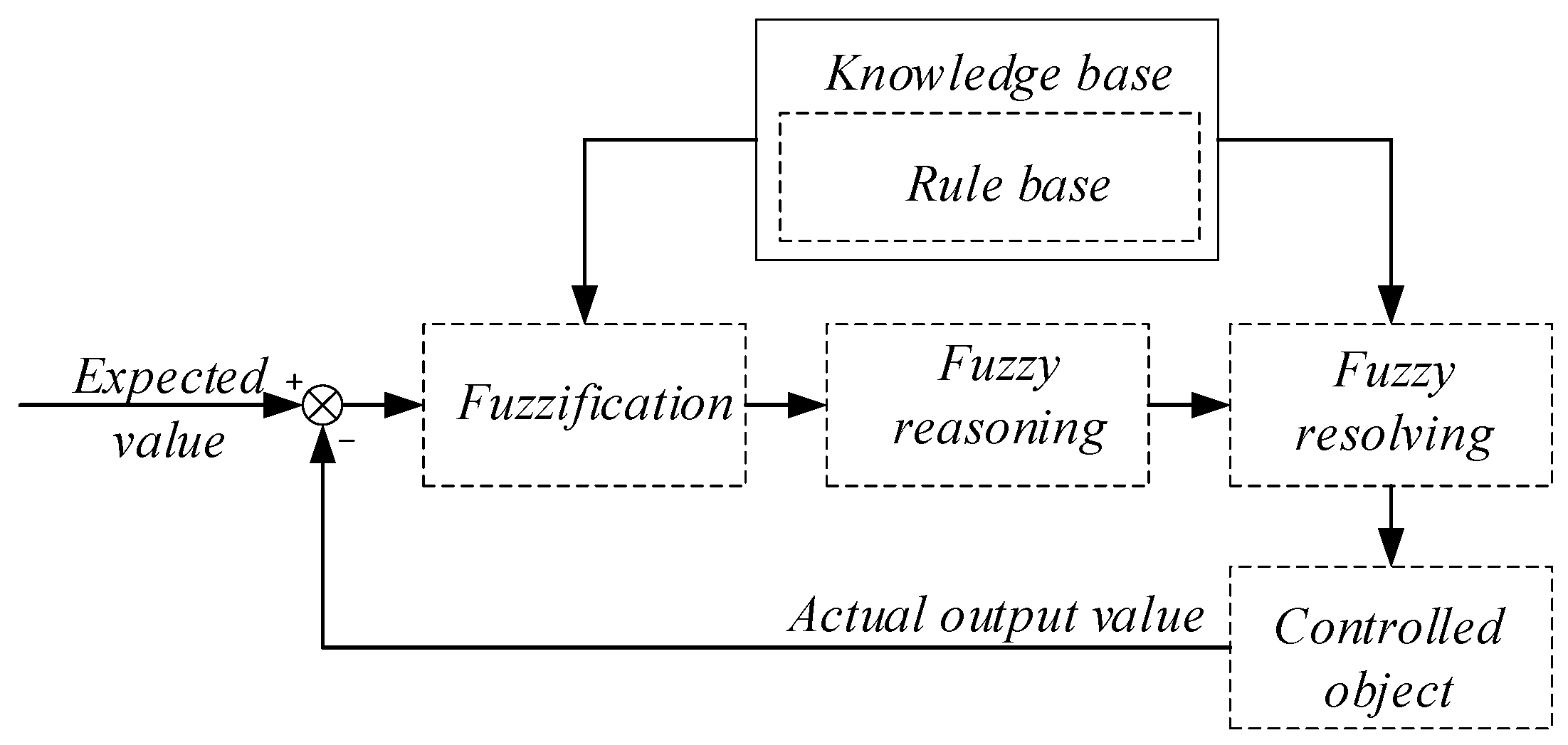
The design of a fuzzy controller mainly consists of four basic links: fuzzification, knowledge base, fuzzy reasoning and fuzzy resolving process, as shown in
Figure 1.
In the figure, the main function of fuzzification is to fuzzify the input’s precise quantity, convert it into a fuzzy quantity, and use the corresponding fuzzy set to describe it. The knowledge base is an important part of a fuzzy controller, which is composed of a database and a rule base. The rule base contains a set of control rules, which are derived from a large pool of expert knowledge and experience. The fuzzy-reasoning link is realized based on the control rules, the relationships are determined by knowledge and experience, and it has the ability to simulate human fuzzy reasoning. The fuzzy quantity generated by the logic judgment is converted into the precise quantity in the actual control application by the fuzzy solution.
3. Steering and Braking Cooperative Control Model
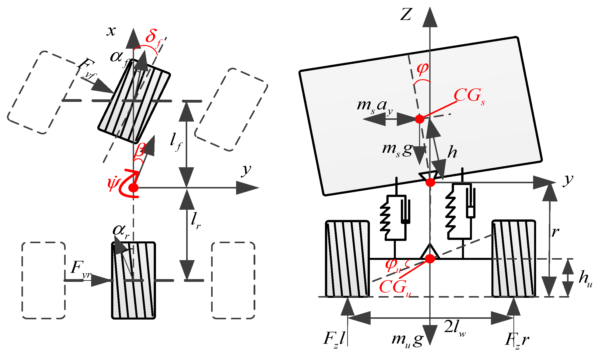
To avoid the delay effect of the complex system in the calculation, this study assumed a linear relationship between the tire lateral force and the tire slip angle. The four-degree-of-freedom(4-DOF) vehicle model was finally selected as the research object. As shown in
Figure 2, this model is an ideal linear model that can effectively describe the vehicle’s dynamic characteristics of the lateral, yaw and roll directions. The 4-DOF commercial-vehicle dynamics model assumes that the longitudinal speed is constant, and the tire sideslip characteristics are not considered.
Referring to [
15], the lateral displacement and yaw angle can be written as shown in Equation (4).
By combining Equations (3) and (4), the steering control model with a front-wheel angle as the input was obtained.
where
is the front-wheel angle and
is the system state variable. The coefficient matrix is as follows:
For Equation (5), the steering and braking cooperative control model can be obtained by applying active yaw moment
,
where
.
The discrete cooperative control model of steering and braking was obtained through the “C2D” command of MATLAB:
Referring to the multi-point preview theory [
24], this study obtained the road update model. The dynamic process of road preview is expressed by Equation (8):
where
is the matrix of road information at step
,
is the shift register matrix,
is the road update matrix, and
is the coefficient of the road update matrix, as follows:
By combining Equations (7) and (8), the augmented model containing the road information was obtained, as shown in Equation (9).
where
To simplify the derivation, the road update item was removed to obtain the steering and braking cooperative control model, including the road information.
A detailed description of each symbol in the equation is shown in
Table 1.
4. Cooperative Controller
The path tracking part is designed by weighing the tracking error and yaw angle deviation of the preview point, and the vehicle stability part is designed by weighting the roll angle deviation. Therefore, the path-tracking cooperative control cost function
considering vehicle stability is shown in Equation (11):
where
is the weight matrix of the control input,
is the weight coefficient of the angle input,
is the weight coefficient of the active yaw moment input,
is the weight matrix of the cost function, and
are the weigh coefficients of lateral displacement, yaw angle and roll angle, respectively.
Referring to [
19],
is set to
for convenient derivation and calculation. Based on the LQ theory, the optimal control input was obtained by iterating the Riccati difference equation with the initial condition
.
Therefore, the optimal control sequence is:
Through deduction, the optimal input
was obtained:
5. Fuzzy Control of Self-Adjusting Weight Coefficient
According to [
12], the weight coefficients
and
in the cost function seriously affect vehicle path-tracking performance.
is set as a constant for design convenience. The vehicle path-tracking effect and stability were optimized by adjusting the size of
and
online. In this study, the fuzzy logic toolbox in MATLAB was used to optimize the weight coefficient of the control input. According to practical experience, lateral displacement deviation and roll angle are important parameters that affect tracking accuracy and stability. Therefore, they were used as the control inputs for the fuzzy controller.
is defined as the regulatory factor of
, and
is defined as the regulatory factor of
. The two regulatory factors are the outputs of the fuzzy controller.
The fuzzy rule in this study was to reduce the path-tracking deviation as much as possible while ensuring better vehicle roll stability. When the vehicle is in a dangerous condition, to ensure driving safety, should be appropriately reduced. When vehicle roll stability is good, attention should be paid to tracking accuracy and should be appropriately reduced.
Firstly, the lateral displacement deviation and the roll angle are normalized:
where
is the lateral displacement deviation and
and
represent the peak value of
.
The adjustment equation of the regulatory factor can be defined as shown in Equations (17) and (18):
where
and
are the initial values of the weight coefficients.
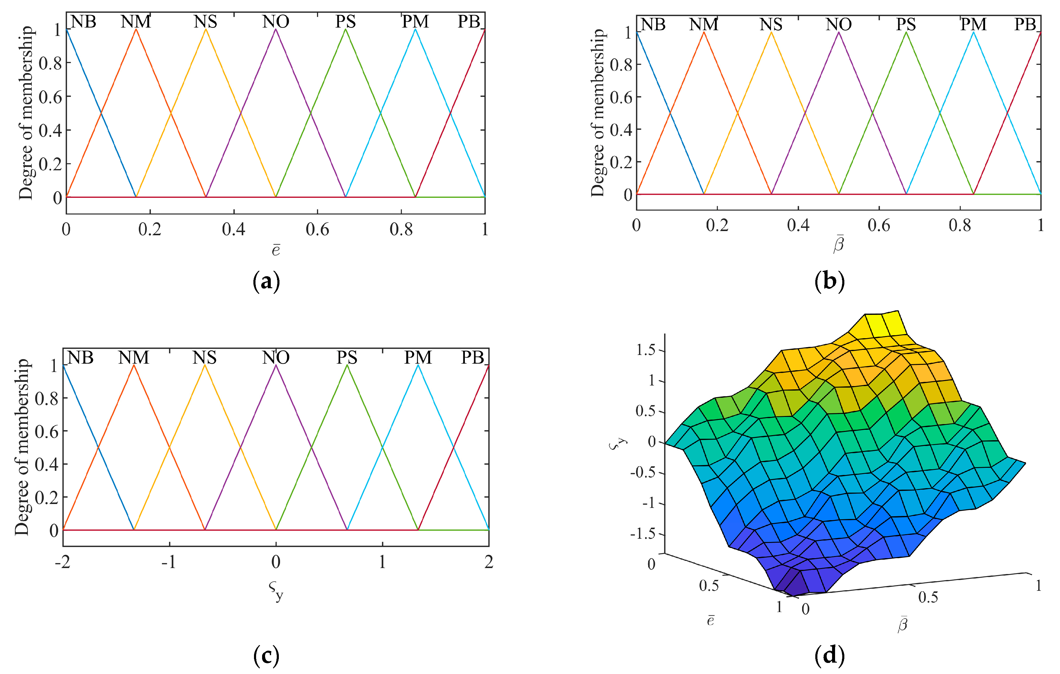
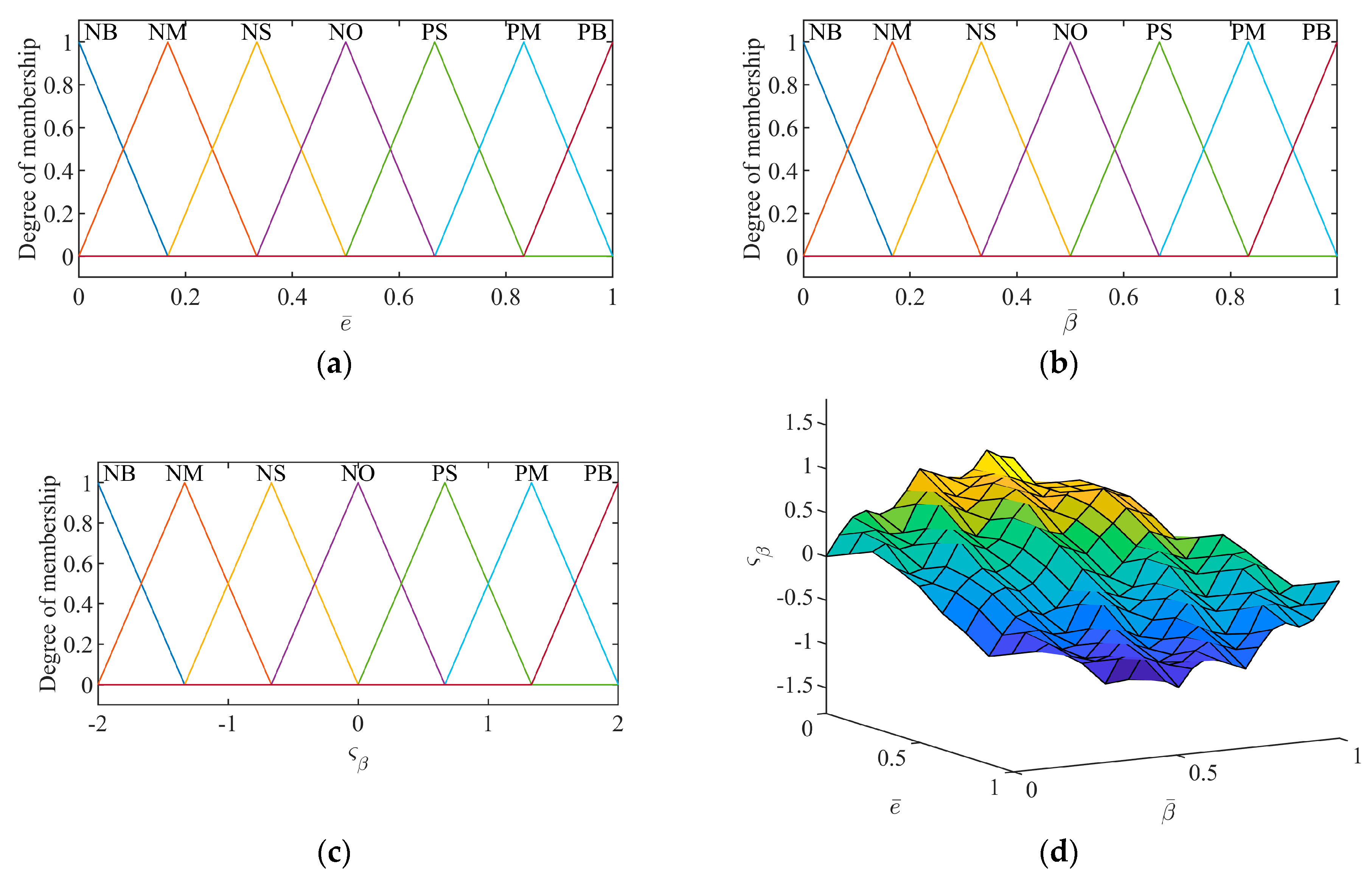
Through the normalization process above, the control input’s domain can be set to [0, 1]. The domain of the two output variables can be set to [−2, 2]. The fuzzy set of input and output variables t is represented as {NB NM NS NO PS PM PB}. The triangle function is selected for the membership function of input and output variables. The fuzzy control rules of
and
are shown in
Table 2 and
Table 3. The membership functions are shown in
Figure 3 and
Figure 4.
6. Co-Simulation and Hardware-in-Loop Experiments
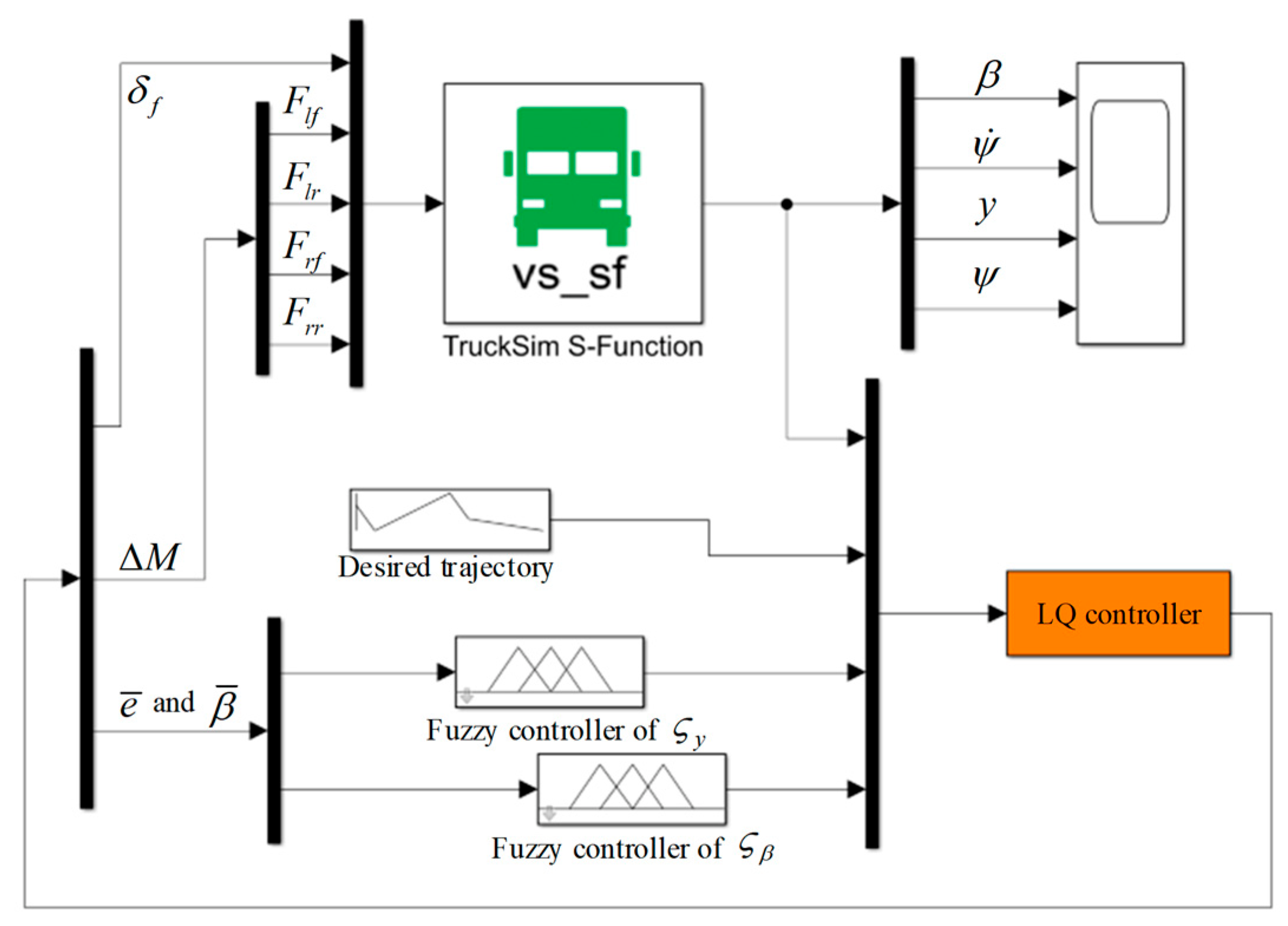
To demonstrate the superiority of the fuzzy LQ controller, a simulation system was designed, as shown in
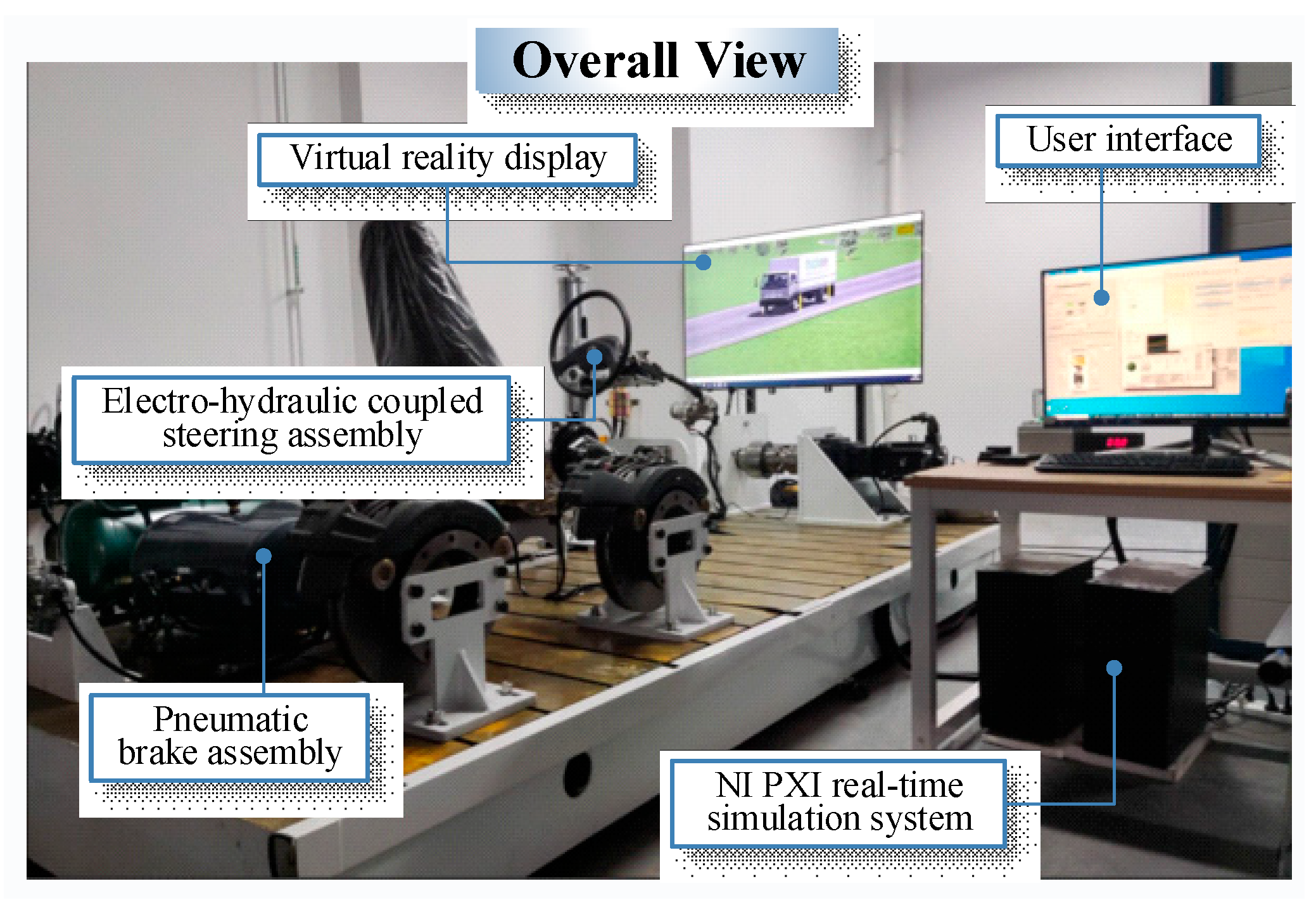
Figure 5. Then, the commercial vehicle hardware-in-loop experiment bench was built, as shown in
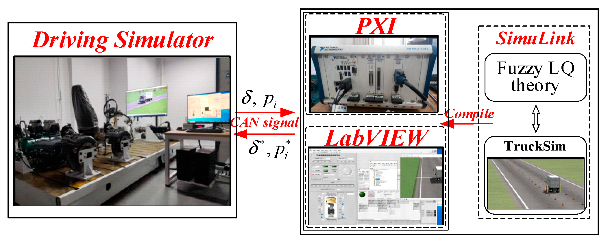
Figure 6. The hardware-in-loop experiment bench uses a real commercial vehicle steering and brake-executive assembly. Firstly, the fuzzy LQ controller is compiled into the NI PXI real-time system for calculation, and the expected angle and braking pressure are obtained. Then, the expected decision is sent to the platform for tracking by the CAN signal, and the tracking value is fed back. Finally, the fuzzy LQ controller calculates the tracking value again with the highly simulated vehicle model in TruckSim to complete the closed loop. For details about the experiment bench, please refer to [
19].
The system control flow of the hardware-in-loop experiment is shown in
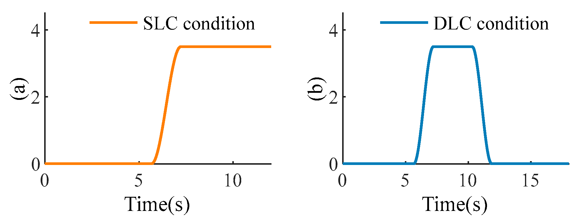
Figure 7. The road information used in the experiment is shown in
Figure 8. The single-line-change path is the test condition for Scenario 1, and the double-line change path is the test condition for Scenario 2.
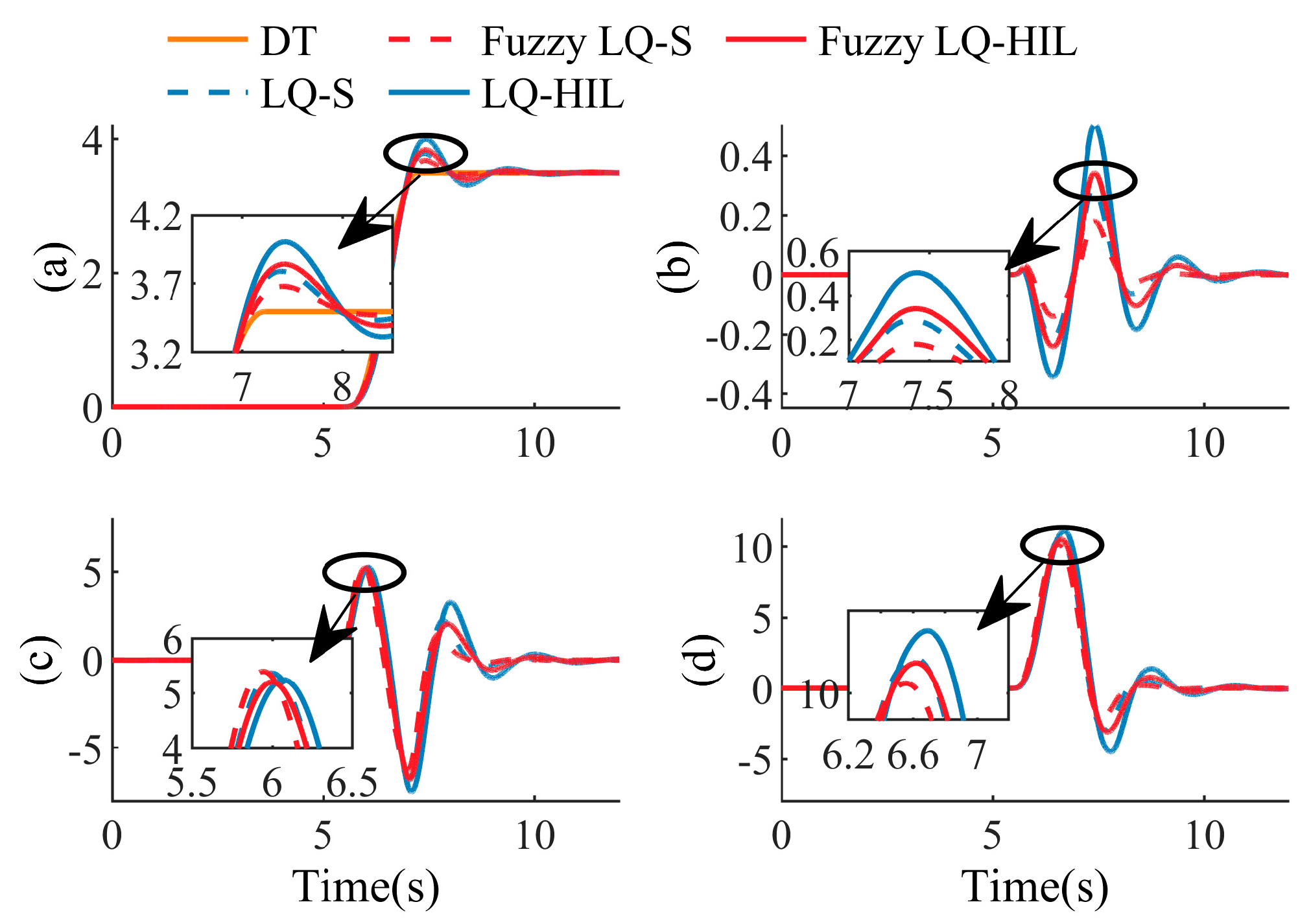
Scenario 1: The Single line-change condition at 80 km/h. Where DT represents the desired trajectory, LQ-S represents the simulation result of the linear quadratic controller, the fuzzy LQ-S represents the simulation result of the fuzzy linear quadratic controller, LQ-HIL represents the experimental result of the linear quadratic controller, and fuzzy LQ-HIL represents the experimental result of the fuzzy linear quadratic controller. The initial weight of the cost function is set as:
As shown in
Figure 9a,b, both tracking controllers can ensure a better tracking effect. Specifically, when the vehicle runs between 5.5 and 6.5 s, the fuzzy LQ controller adjusts
down and
up to meet the requirements of path-tracking accuracy. By increasing the control weight of the front wheel angle, a more aggressive steering decision can be made, and a better path-tracking effect can be achieved.
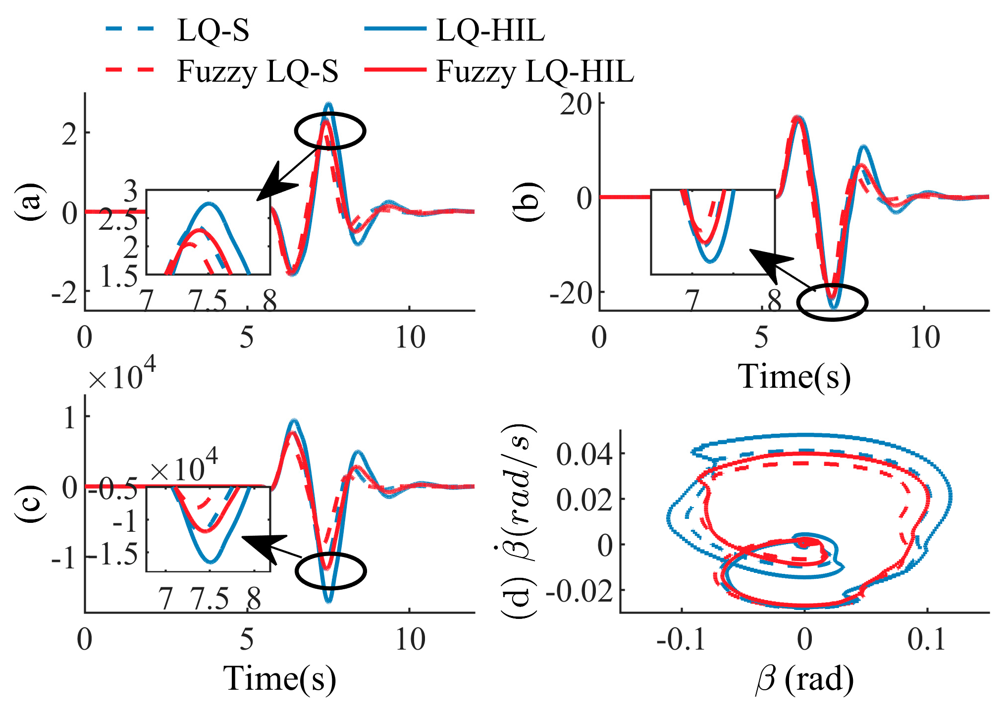
As shown in
Figure 10a, both controllers ensure that the roll angle is no greater than 3 deg. Between 7 and 8 s, the vehicle stability is slightly worse. The fuzzy LQ controller adjusts
to become small. Driving safety can be improved by increasing the proportion of the stability control input. It can also be seen from
Figure 10c that the fuzzy LQ control strategy has better stability than the LQ control strategy.
In summary, the fuzzy LQ controller can adjust the control of the vehicle using path tracking and anti-roll adaptively, according to the driving scenario, to obtain a better control effect. When the vehicle-tracking accuracy is poor, the steering control weight is increased. When poor vehicle stability is detected, the steering weight is weakened, and the braking weight is increased to ensure driving safety.
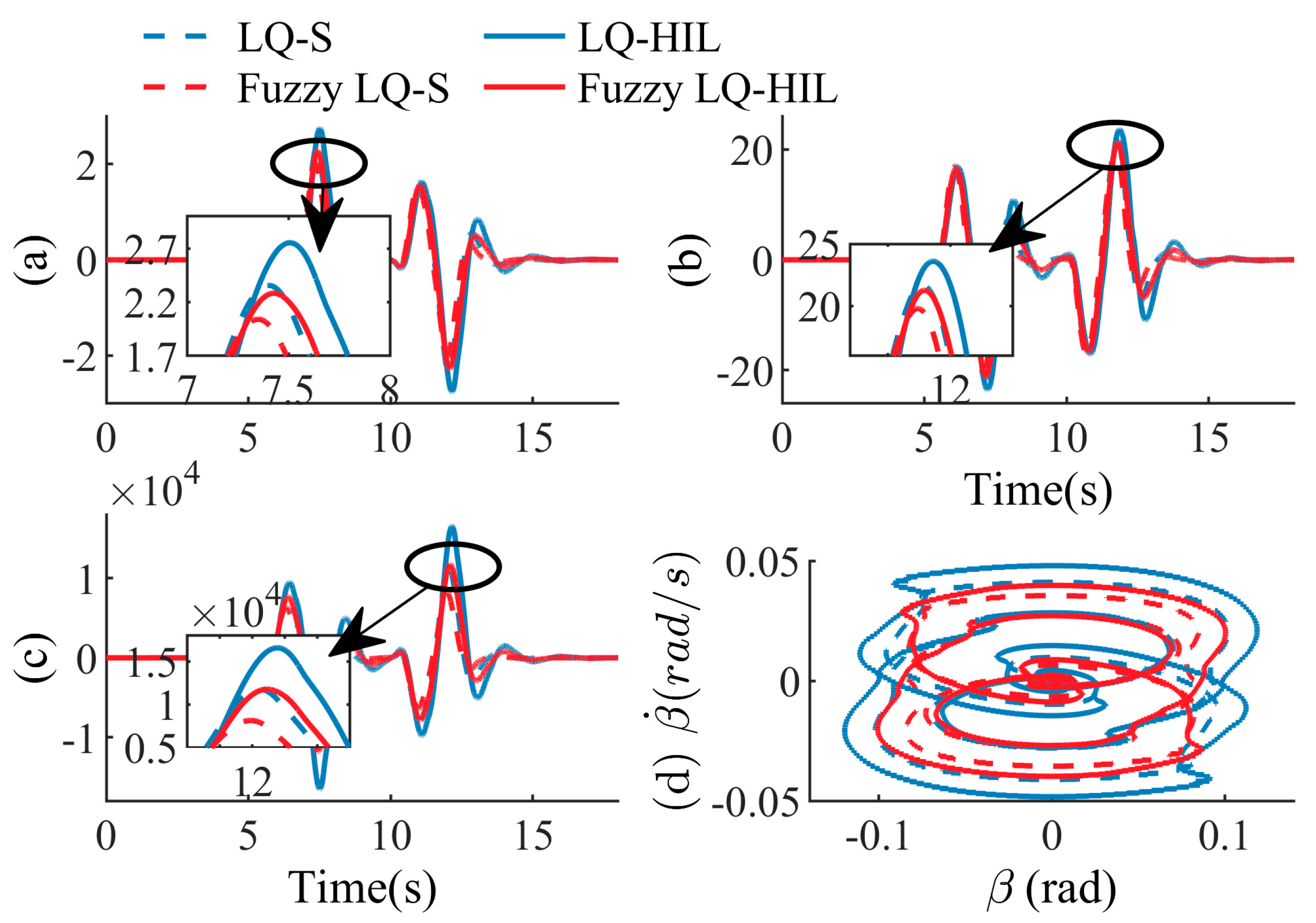
Scenario 2: Double line-change condition at 80 km/h. The initial weights of the cost function are the same as in Scenario 1.
As can be seen from
Figure 11a,b, the effect of the LQ controller decreased as the curvature of the tracking path increased while the control weight remained unchanged. The fuzzy LQ controller still guaranteed a good track-tracking effect. It proves that the fuzzy LQ controller has good environmental adaptability. As can be seen from
Figure 11d, the yaw angle of the fuzzy LQ controller is still globally smaller than that of the LQ controller.
By comparing
Figure 9a and
Figure 12a, it can be seen that when the driving scenario deteriorated, the fuzzy LQ control adjusted the control value according to the driving scenario, which still ensures good roll stability. As can be seen from
Figure 12c, the fuzzy LQ controller tends to calculate small brake intervention strength when the vehicle has good stability.
In conclusion, both controllers can ensure better path-tracking effects and vehicle roll stability. The fuzzy LQ controller can effectively improve the adaptability of the control strategy to the scene by optimizing the weight of the cost function online. The fuzzy LQ controller can ensure a better path-tracking effect and improve vehicle stability in the ultimate working condition. Its performance is better than the traditional LQ controller.
7. Conclusions
A fuzzy LQ controller was proposed in this paper, which could take into account the roll stability of the vehicle in the course of path-tracking and improve the adaptability of the controller to the driving scenario. Firstly, the LQ controller was designed in this study to solve the control object conflict problem between the path-tracking accuracy and the vehicle’s roll stability. However, the classical LQ controller needed to design the cost function in advance. As a result, the vehicle in the actual simulation had poor adaptability to complex and changeable driving conditions. Therefore, a fuzzy LQ controller was designed based on the experience of real drivers. The weight of the cost function was optimized online using the road-tracking deviation and roll angle. Finally, the performance of the fuzzy LQ controller was verified using co-simulation and hardware-in-loop experiments.
The results show that, compared with the classical LQ controller, the fuzzy LQ controller can optimize the weight of the cost function online and improve the roll stability of the vehicle while ensuring better path-tracking accuracy. The following conclusions can be summarized from this study:
- (1)
To solve the problem of driving safely under extreme working conditions, a path-tracking controller that considers roll stability was designed based on the LQ theory.
- (2)
The weight of the classical LQ controller’s cost function was fixed, and the function’s adaptability to the driving scenario was poor. Therefore, a fuzzy LQ controller with a self-adjusting weight coefficient was designed. The dynamic performance of the system can be improved effectively by optimizing the weight coefficient of the cost function online.
In the future, we will try to include uncertain input elements of the driver and try to solve problems such as changes in the system-model parameters. To better verify the practicability of the control scheme, the fuzzy LQ controller designed in this paper will carry out real vehicle tests on various driving conditions.


