Article

Developing and Testing of the Principle Prototype for Efficient Micro-Damage Fine Stripping of Asphalt on the Surface of Reclaimed Asphalt Pavement

1
Center for Advanced Jet Engineering Technologies (CaJET), School of Mechanical Engineering, Shandong University, Jinan 250061, China
2
Key Laboratory of High-Efficiency and Clean Mechanical Manufacture, Ministry of Education, Shandong University, Jinan 250061, China
3
National Demonstration Center for Experimental Mechanical Engineering Education, Shandong University, Jinan 250061, China
4
Shandong HI-SPEED Group, Shandong Expressway Building, 8# Longao North Road, Lixia District, Jinan 250014, China
5
School of Qilu Transportation, Shandong University, Jinan 250061, China
6
School of Mining, Liaoning Technical University, Fuxin 123000, China
7
School of Automobile, Chang’an University, Xi’an 710064, China
*
Author to whom correspondence should be addressed.
Machines 2023, 11(3), 367; https://doi.org/10.3390/machines11030367
Submission received: 1 February 2023 / Revised: 2 March 2023 / Accepted: 7 March 2023 / Published: 8 March 2023
(This article belongs to the Collection Computational Product Design with Artificial Intelligence)

Abstract

:
In the current recycling process of reclaimed asphalt pavement (RAP), due to the serious damage of aggregate gradation and the large amount of aged asphalt still wrapped around the surface of the treated aggregate, the low recycling rate and poor performance of the recycled asphalt mixture are the major problems of RAP. In view of the shortcomings of RAP recycling technology, it is urgent to research new treatment methods and design specialized asphalt-stripping equipment to solve the existing problems. In this paper, based on theoretical analysis and EDEM discrete element simulation, a principle prototype for efficient micro-damage fine stripping of asphalt on the RAP surface is developed and tested. The results demonstrate that the principle prototype has a satisfactory asphalt-stripping effect and achieves fine stripping of aged asphalt on the surface of aggregate without large-scale crushing. This principle prototype has significant engineering application values, which provides design solutions and data support for further equipment development.

1. Introduction

Due to heavy traffic, asphalt–concrete pavements can be damaged to various degrees, which requires maintenance, renovation or reconstruction. Plenty of reclaimed asphalt pavement (RAP) will be generated in the maintenance process [1], which not only occupies land resources and raises secondary environmental problems, but also causes a great waste of natural resources [2]. Therefore, how to realize the efficient regeneration of RAP has become an urgent issue to be solved.
Research shows that asphalt pavements suffer from natural factors, traffic loads, and physical and chemical interactions between asphalt and mineral aggregate over the long time of its service, eventually leading asphalt aging to occur [3]. After asphalt is aged, its chemical composition changes, resulting in the decline of each performance index [4]. However, aged asphalt can be blended with a low-viscosity rejuvenator and combined with aggregate in RAP to produce a recycled mixture. Therefore, the essence of the recycling technology of RAP at this stage is to select the aggregate through crushing and screening, add the rejuvenator to restore the aged asphalt, and then heat and mix it with a certain proportion of asphalt, new aggregate and other materials to produce a recycled asphalt mixture for pavement structures [5]. However, traditional machines such as jaw crushers or hammer crushers are generally applied for the crushing treatment in the recycling process [6], which causes the excessive refinement of some aggregates and damage to the original gradation of the asphalt mixture. In addition, the simple crushing process cannot effectively separate asphalt and aggregate. After treatment, considerable aged asphalt mortar still adheres to the aggregate surface, leading to the fact that the utilization rate of RAP in the actual recycling is restricted to a low level. If the amount of RAP in the recycled mixture is increased, it would have a negative impact on the low-temperature crack resistance and water stability of the product [7]. In general, when increasing RAP content in an asphalt mixture under the premise of ensuring a certain road performance, the following issues should be considered: additional processing and quality control, changing of virgin binder grade, preparation of materials for the mixture design, and blending of the virgin and RAP binders [8]. According to the statistics of Reclaimed Asphalt Pavement in Asphalt Mixtures: State of the Practice, a similar pavement performance to virgin asphalt pavement can still be obtained if the RAP content in the recycled asphalt pavement is maintained at 30–50%, and higher grade binders or a reasonable mixture design are adopted [9]. However, the aforementioned processes are at the cost of chemical usage and the environment. In contrast, the proposed method is undoubtedly a more economical and environmentally friendly method to increase RAP content through mechanical processing and quality control.
In order to ameliorate the aforementioned problems, pre-treatment should be conducted before hot mixing to remove the asphalt on the aggregate surface and enhance the aggregate performance in the recycled mixture. At present, the removal methods of surface impurities mainly include heat treatment, chemical treatment, and mechanical treatment [10]. For example, taking advantage of the rapid change in temperature, Pandurangan [11] kept the recycled aggregate in a furnace at 500 °C for 2 h, and then took it out and soaked it in water to peel off the attached mortar. Ma [12,13] partially washed RAP aggregates with a mobilized RAP binder and immobilized RAP binder, respectively, which proved that the interaction between asphalt and aggregate can be improved by adding a binder in the form of surface free energy, and the content of effective asphalt in the recycled mixture can be increased. Dimitriou [14] applied the rolling effect produced by a rotating mixer and the impact of water to remove smaller particles, dust and mortar with weak cohesiveness from the concrete aggregate. Dilbas [15] and Babu [16] placed concrete aggregate in a rotating Los Angeles grinding cylinder containing steel balls, using the grinding and impact effects to reduce the mortar attached to its surface. Zhao [17] blasted hard particles on asphalt pavement through shot blasting, which applies the high-speed impact of granular materials to achieve the effect of cleaning debris and attachments on the surface and effectively improved the skid resistance of asphalt pavement. Compared with heat and chemical treatments, the mechanical treatment method has the advantages of process simplicity and cost-effectiveness, and does not introduce chemical impurities, so it is theoretically more suitable for the practical engineering application of RAP regeneration. However, high energy-consumption, low efficiency and serious wear are the major problems of mechanical treatment machines. On the other hand, the optimization of these machines needs to be verified by a large number of experiments or engineering applications, so research and development has been limited. How to improve the efficiency and treatment effect of these machines has once again become a difficult problem for scholars. With the rapid development of computer-aided engineering (CAE), the discrete element method (DEM) provides an approach to solve such engineering problems. DEM is a numerical method specially applied to solve the problems involving discontinuous media, such as geotechnical, mining and metallurgical engineering, which can accurately calculate the force and velocity of granular materials during motion. For example, Kalala [18] applied the DEM method to study the influence of the lining plate on the working state of the dry mill, and found that the total impact energy consumed in the mill decreased with the wear of the lining plate, while the friction energy consumed increased in contrast. Ren [19] studied the influence of different process parameters of a tower mill on its working performance based on the DEM method, and summarized that the grinding force and power consumption increased with the increase in the speed, diameter and medium filling rate of the agitator. Through DEM simulations of different shot-blasting blade structures, Choi [20] found that the efficiency can be improved by 20% after optimizing the number of blade fillets and bulges, and the shot-blasting test results were in excellent agreement with the results of the DEM.
To develop an RAP asphalt-stripping principle prototype, this paper starts from the structural composition of an asphalt mixture, considers the existing products and the recovery treatment technology with their surface impurity removal effects, applies commercial EDEM software to conduct a simulation, and fabricates the mechanical structure. Finally, multiple controlled mechanical tests through an electronic universal testing machine [21,22] are conducted to evaluate the asphalt-stripping effect, and the influence of different process parameters on the treatment effect is verified. This equipment integrates different socialized manufacturing resources, which conforms to the trend of socialization, customization, and service in the manufacturing industry [23]. In the future, when a mature RAP asphalt-stripping machine is introduced in various regions, a network–physical–social connection could be established through decentralized social media to form a complex dynamic autonomous system [24]. Through the integration and customization of products and services, the utilization of RAP in the whole society can be comprehensively promoted.

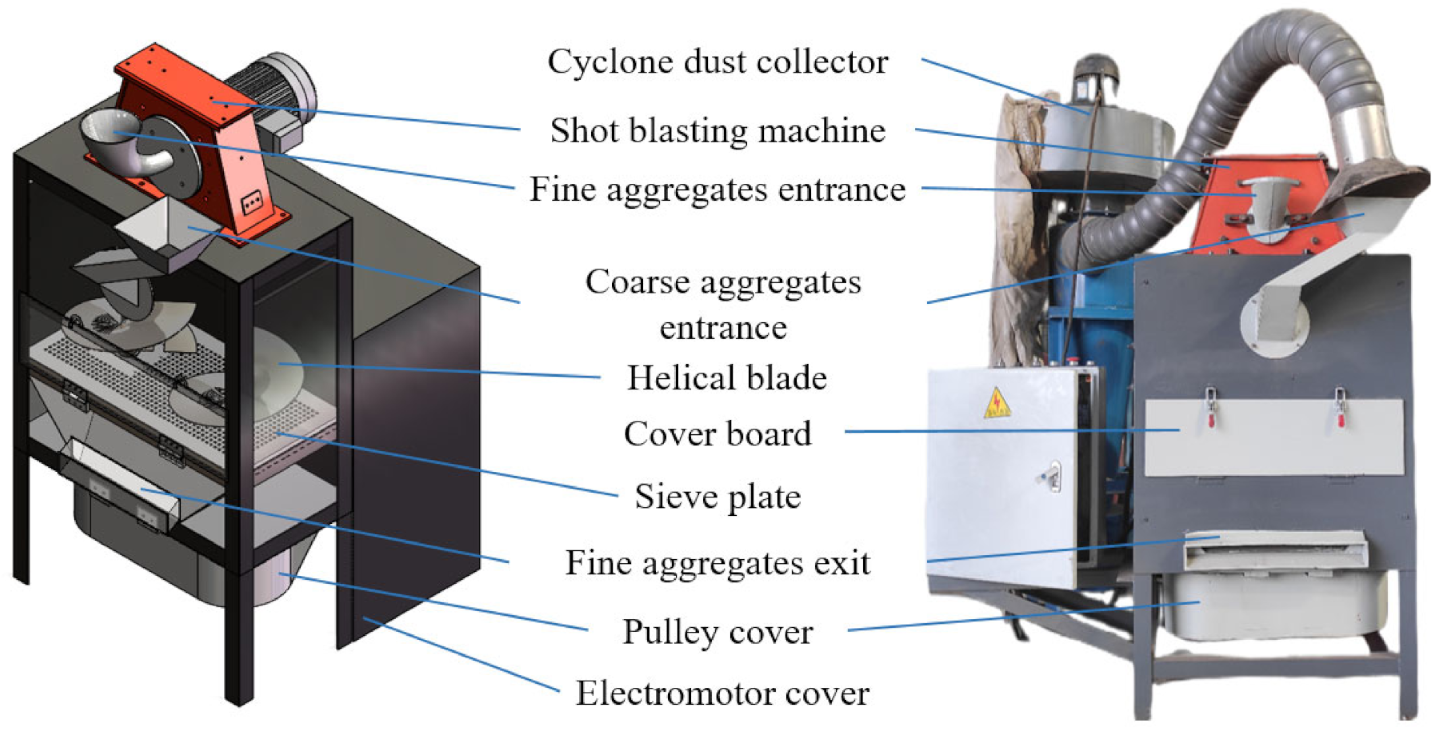
2. Structure Design of RAP Surface-Asphalt-Stripping Principle Prototype

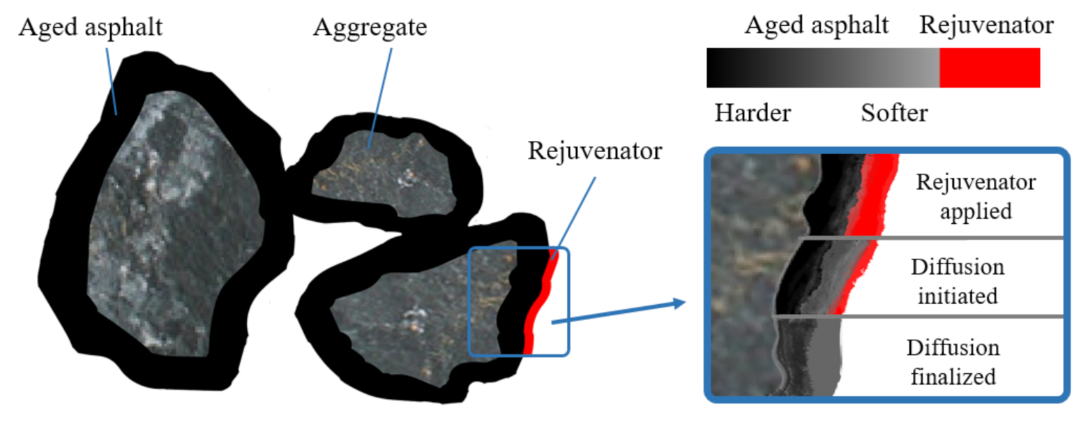
2.1. Structural Composition of Asphalt Mixture

In addition to aggregates with various sizes, the RAP obtained from pavement milling also contains a large number of aggregates bonded by aggregate and aged asphalt. The physical and chemical properties of aggregates are stable, and their mechanical properties are not easily changed. Therefore, they can be directly used for recycled mixtures. However, the hardness of asphalt on the aggregates increases after aging, and then its physical and mechanical properties become unstable. During the mixing and construction of a recycled mixture, aggregates loosen easily, fracture and deform [25]. Due to the existence of aggregates in RAP, in the production of a recycled mixture, it is necessary to add a rejuvenator to restore the performance of aged asphalt. Nevertheless, in the actual recycling process, because the aged asphalt wrapped around the aggregate surface is usually very thick, the rejuvenator cannot fully penetrate it [26], which leads to the failure to effectively restore the aged asphalt in the deep layer (as shown in Figure 1). As the aged asphalt is difficult to make fully miscible with the new asphalt in the process of hot mixing, it will eventually result in the low recycling rate of RAP and the poor performance of the recycled mixture.

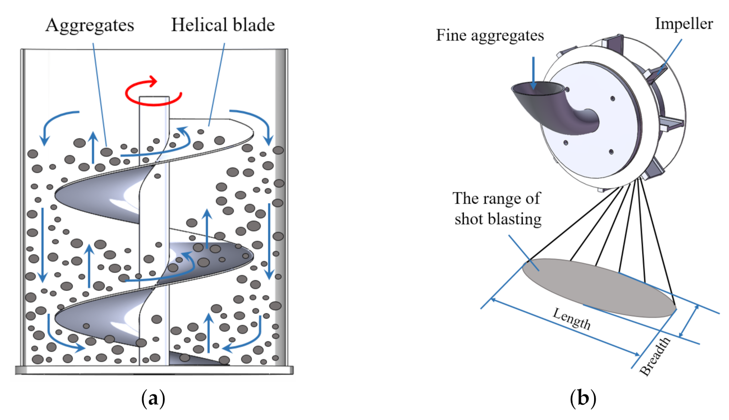
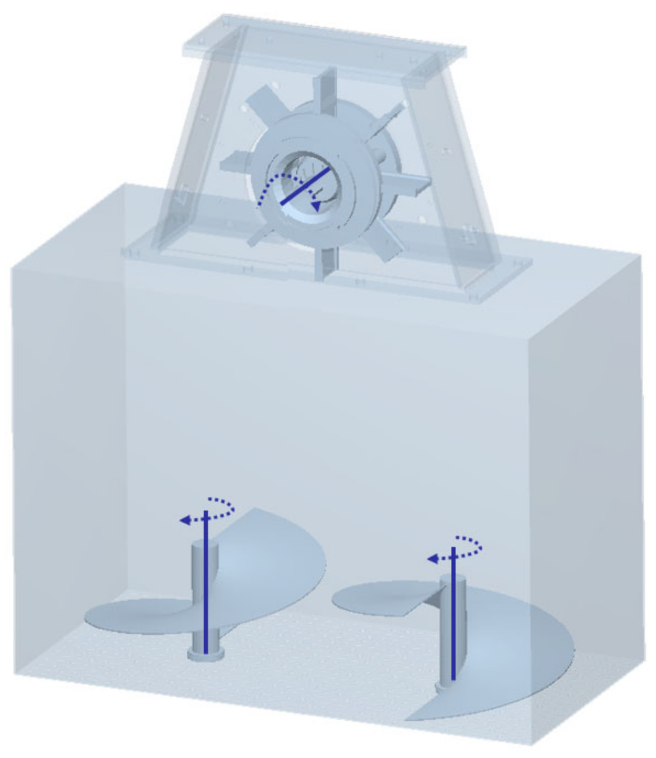
2.2. Functional Analysis and Structural Scheme of the Stripping Structure

In order to improve the recycling rate of RAP and improve the mechanical properties of the recycled mixture, it is necessary to separate the aged asphalt and aggregate in the RAP for subsequent treatment. At present, the main method for the separation of an asphalt mixture is to apply mechanical forces to carry out the indiscriminate large-scale crushing treatment of RAP, so that the RAP with an uneven quality becomes a mixture of aggregate and asphalt mortar with near uniform sizes. However, this method will cause the excessive refinement of aggregate. In addition, because the crushed aggregate size is close to asphalt mortar, the particle size after screening cannot reflect the actual grading, resulting in the deviation of asphalt content with the same grading, which will have a significant impact on the mechanical performance of recycled mixtures. Therefore, the crushing treatment is not completely applicable to the separation and regeneration of anasphalt mixture. It is necessary to develop a stripping mechanism dedicated to the fine treatment of the aggregate’s surface asphalt. Then, the stripped asphalt mortar can be fully mixed with the rejuvenator to complete the deep regeneration, and the aggregate can be directly used for the recycled mixture after reasonable setting and grading.
The stripping mechanism was developed based on the refined asphalt treatment concept which bans forced crushing. With reference to technology for the removal of the relatively mature surface impurities, a vertical mill with a spiral mixing structure can meet the requirements of asphalt stripping on the aggregate surface, and its energy utilization rate can reach 26.3%, which is much higher than that of the traditional ball mill [27]. As shown in Figure 2a, due to the rotation of the internal spiral stirring blade, the grinding medium and aggregates can circulate up and down in the axial direction of the spiral shaft and create a circular movement in the cylinder. Affected by gravity and the extrusion generated by the spiral rotation, the aggregates can be effectively ground by friction and shear force [28]. By applying this principle, the stripping mechanism adopted the box structure and spiral blades. The box structure was used to limit the degree of freedom in the horizontal direction of the aggregates and offer supports at the bottom. The turning of the blades makes the aggregates squeeze and grind each other, which forms the stripping effect. Moreover, there is enough space in the upper part of the box structure to avoid the forced crushing of the aggregates during processing. The bottom layer aggregates in the box structure are subject to the gravity of the upper aggregates. It should be noted that the surface pressure on the aggregates from bottom to top is gradually reduced, so the stripping effect is also gradually reduced correspondingly. Therefore, for the aggregates at the top of the box structure, an additional treatment needs to be adopted. As a reliable method, shot-blasting surface-cleaning technology is widely used in many fields [29]. In this asphalt-stripping scenario, the shot-blasting machine was set above the spiral structure. The projectiles of the shot-blasting machine were firstly accelerated by the shot-separating wheel. Subsequently, they were thrown out of the window of the directional sleeve to the blade. After being further accelerated by the rapidly rotating blade, the projectiles spread under the effect of centrifugal force, hit the upper layer of aggregates in the box structure at high speeds, and form a jet grinding area. As a result, the shot-blasting machine can clean the aggregates with aged asphalt on the surface, for which the working principle is demonstrated in Figure 2b. In order to reduce process energy consumption and avoid excessive refining of aggregates, media free grinding was adopted. Namely, coarse aggregates (aggregates with particle size greater than 4.75 mm) were used to extrude and grind the asphalt with their own edges and corners. At the same time, fine aggregates (aggregates with particle size less than 4.75 mm) were used as projectiles in the shot-blasting machine to avoid the introduction of other impurities. Because the physical characteristics of coarse and fine aggregates are the same, the particle size of coarse aggregates would not be damaged during the grinding process.
The stripping structure is composed of spiral blades, a box structure and a shot-blasting machine, realizing the process of self-grinding of coarse aggregates and the shot blasting of fine aggregates. With the treatment of spiral blades, the combined effects of centrifugal force, gravity and friction make the aggregates move in an orderly way and have a basic force balance. However, due to the morphological differences between aggregates, the force is uneven and will change at any time. Affected by rolling and sliding, the aggregates in the box structure generate a strong local shear force, extrusion force, abrasion stripping effect, and scrubbing effect. Aided by the abrasive effect of the shot-blasting machine, the high-efficiency and refined stripping of surface aged asphalt can be achieved without the large-scale crushing of aggregates, and the phenomenon of over crushing and the agglomeration of particles can be greatly reduced.

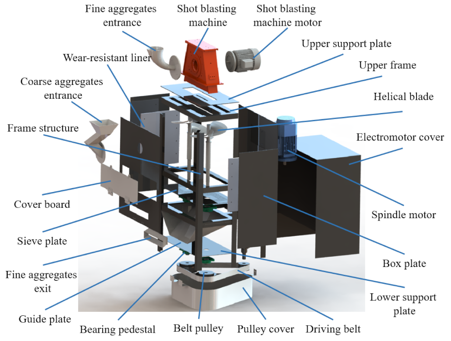
2.3. Modeling of the Principle Prototype

As shown in Figure 3, the shot-blasting machine is located on the top of the box structure enclosed by plates and fixed on the upper support plate. In order to adapt to the range of shot blasting, the box shape was set as a cuboid. Outside of the box structure, there is a coarse aggregates entrance, and inside of the box plates, there are wear-resistant liners. The inner space of the box structure is an aggregates handling cavity. The bottom of the box structure is a piece of 4.75 mm thick sieve plate, on which a pair of helical blades are configured. The helical blade shafts are mounted on the sieve plate and the lower support plate through the bearing seat. A guide plate is arranged between the sieve plate and the lower support plate and is connected to the exit point of the fine aggregates. In order to avoid damage to transmission system caused by excessive vibration and dust, a belt drive was selected to rotate the helical blade shafts. The belt drive is set under the lower support plate and is driven by a speed reducer at the rear of the box structure. The motor and the pulley are covered by a motor cover and a pulley cover on the outside, respectively. The prototype uses a frame welded with angle iron to support the weight of each part, and each part is fixed with a bolt connection to the frame. SolidWorks was applied to build the three-dimensional model of the whole machine and verify the strength of non-standard structures such as the spindle, helical blade, box structure and support. Finally, after the assembly of all functional modules, a global interference detection was conducted.

3. Simulation of the Prototype Based on EDEM

3.1. Basic Theory of DEM

3.1.1. Introduction to DEM

As a discontinuous numerical simulation method, the core idea of DEM is to treat the research object as a composition of some independent and discrete particle units, and the interaction between the units can be calculated according to the relationship between force and displacement [30]. When the principle prototype works, the aggregates in the treatment chamber move, collisions occur between the aggregates, and between the aggregates and the parts. These collisions determine the force characteristics and movement rules of the aggregates in the treatment chamber. The motion of the aggregates in the treatment chamber is regarded as a discontinuous particle flow. Based on contact theory and Newton’s second law, the motion state of the discrete body in each step can be obtained, and then the motion of the aggregates can be simulated, finally reflecting the mechanical behavior of the aggregates under the action of blasting and grinding.
The general solution process of the DEM is to divide the solution space into a discrete element matrix and connect adjacent units by connecting elements (i.e., contact model) according to practical problems. The relative displacement between units is a basic variable. Normal and tangential forces between units can be obtained from the relationship between force and relative displacement. The acceleration of the unit is calculated using Newton’s second law based on the resultant force and resultant moment caused by the forces acting on the unit in all directions and other physical fields acting on the unit. Time integration is performed to obtain the velocity and displacement of the unit, and physical quantities such as speed, acceleration, angular velocity, line displacement and the rotation angle of all units at any time can be obtained.

3.1.2. Equation of Motion—Newton’s Second Law

According to the dynamic theory, the motion of solid particles in the space coordinated system is mainly composed of translation and rotation, and the total motion mode of particles can be the superposition of the two, and the equation of motion is [31]
m i d v ¯ i d τ = f ¯ i I i d ω ¯ i d τ = T ¯ i
where m i is the mass of particle i; v ¯ i is the velocity of particle i; I i is the moment of inertia of particle i; ω ¯ i is the angular velocity of particle i; f ¯ i is the total force exerted on particle i; and T ¯ i is the sum of the torques exerted on particle i by the collisions between particles.
When particle j collides with particle i, the torque acting on particle i can be calculated from the following equation:
T ¯ i j = R ¯ i × f ¯ i j , c
where R ¯ i is the vector at which the centroid of particle i points to the point of contact; and f ¯ i j , c is the contact force of particles i, j.
If k i particles are in contact with particle i at the same time, the total torque to which particle i is subject is
j = 1 k i T ¯ i j
The velocity and position of the particle i after time Δ τ can be obtained by integrating the equations of motion, respectively.

3.1.3. Time Step

In EDEM software, simulation calculations are carried out by means of iteration cycles with time steps. The time step is to regard the motion time of the whole particle system as a superposition of several time periods, which are small and equal, under the assumption that the velocity and acceleration of each particle in a single time step are fixed. From the resultant force and moment obtained previously, according to Newton’s second law of motion, the acceleration and angular acceleration of the mass center can be obtained, so that the velocity, angular velocity, displacement and moment of inertia in the time step can be obtained.

3.2. Configuration of the DEM Simulation Model

3.2.1. Contact Model Selection

The contact model is the core of DEM, which is essential to simulate the contact force of particle–solid collisions and calculate the particle motion information. Different contact types must be established for different simulation objects. Commonly used contact models for EDEM are the Hertz–Mindlin no-slip model, Hertz–Mindlin with JKR model, hysteretic spring, and Edinburgh elasto-plastic adhesion model [32]. As the aging of asphalt will cause an increase in elastic components, the rheological properties of asphalt can be changed from partial viscous to partial elastic [33]. On the other hand, the Hertz–Mindlin non-slip model is used in EDEM by default to model aggregates as a non-viscous and incompressible material.
The resulting contact forces between particles and between particles and geometry are broken down into two forces: one normal force along the contact normal direction and the other tangential force along the contact plane [28]. The normal force F n can be obtained from the formula:
F n = 4 3 Y R δ n 3 2
where R is the particle radius; δ n is the normal overlapping amount; and Y is the equivalent Young’s modulus.
The normal damping force F n d can be expressed as
F n d = 21 6 5 β S n m v n r e l ¯
where m is mass; v n r e l ¯ is a constant of relative speed; and S n is the normal hardness.
If e is taken as the coefficient of resilience, then β and   S n can be calculated according to the following equations:
β = l n e l n 2 e + π 2
S n = 2 Y R δ n
The tangential force F t related to the tangential overlapping amount δ t and tangential hardness S t , can be expressed by
F t = S t δ t
S t = 8 G R δ n
where G is the shear modulus.
The tangential damping force is
F t d = 2 5 6 β S t m v t r e l ¯
where v t r e l ¯ is the tangential relative velocity.
The coefficient of friction is important in the simulation, where μ s is the coefficient of static friction, which affects the magnitude of the tangential force, and the rolling coefficient of friction μ r determines the torque on the contact surface, namely
τ i = μ r F n R i ω i
where R i is the distance from the center of gravity to the point of contact; and ω i is the angular velocity of the particle i at the point of contact.

3.2.2. Material and Geometry Parameter Settings

In order to make the simulation close to the actual operating conditions, the aggregates, particles and prototype parts should be configured in accordance with the actual material. Since particles cannot be set as composites in EDEM, the aggregates in the treatment chamber were defined as aggregates, and the material of the prototype parts was defined as steel. By consulting the relevant literature and conducting calibration experiments, the physical parameters of steel and aggregate were collected, as shown in Table 1, and the contact relationships between different materials are tabulated in Table 2 [34].

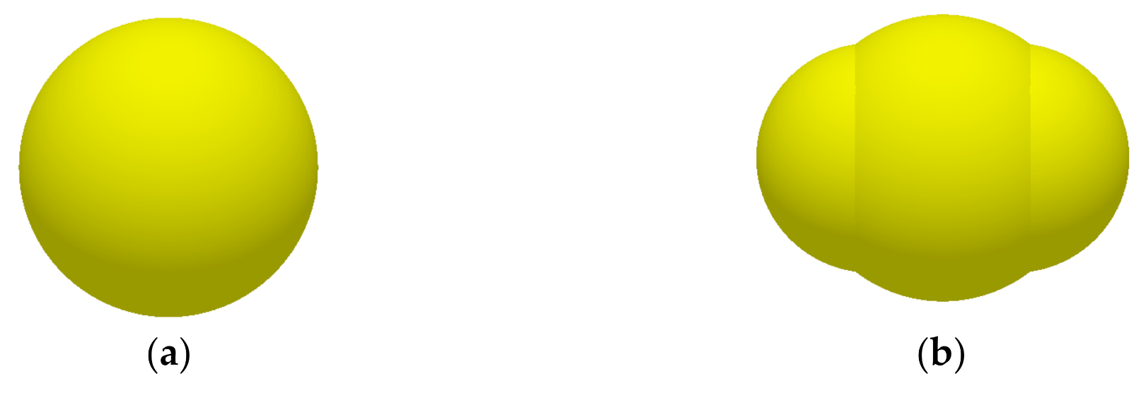
3.2.3. Aggregate Model Setting

The shapes of aggregate in RAP are extremely heterogeneous and impossible to model completely. Actually, it is not necessary to conduct a simulation by applying the actual shape of all aggregates. By constructing special-shaped aggregate models with different length–width ratios, the force results obtained via simulation are similar to that of the actual treatment conditions [35]. The simulation is solved by DEM according to the number of spherical surfaces. If the structure used for particle modeling is too fine, the contact model will result in complex solutions and a low calculation efficiency. Therefore, without compromising the simulation results, the aggregate model should be simplified as much as possible to reduce the number of spherical surfaces. The particle size range in actual treatment was 0–26.5 mm, in which fine aggregates with a particle size of less than 4.75 mm were applied as projectiles. In order to reduce the number of spherical surfaces, the feeding projectile size was unified as 3 mm and the particle generation rate was 4000/s. Aggregates with particle sizes ranging from 4.75 to 26.5 mm were generated according to AC-20 gradation, as shown in Table 3. The generated coarse and fine aggregate models are presented in Figure 4.
The particle generation in particle factories is categorized as dynamic generation and static generation. Specifically, the simulation continues when the particles are generated dynamically, while the simulation is suspended when the particles are generated statically. Considering the processing procedure of filling coarse aggregates first and then blasting, grinding and stirring, the static generation of coarse aggregates and dynamic continuous generation of projectiles are adopted. Four particle factories are applied to model the four particle sizes of coarse aggregates particles correspondingly. Note that the particle size generated by each particle factory has a certain fluctuation, so the normal distribution law is used for the generation of EDEM particles.

3.2.4. Establishment of the Simulation Model

In order to accelerate the simulation, structures such as the drive, support as well as complex connecting components were neglected, and only the stripping structure which has a major influence on the processing effect was retained. The simplified prototype model including pelletizing wheel, directional sleeve, blade, spiral impeller blade and box structure with sieve holes on the bottom was constructed using SolidWorks and imported into the EDEM software. The established geometric model is shown in Figure 5, in which the impeller speed of the shot-blasting machine is 2600 r/min, the rotating speed of the helical blade is 90 r/min and the rotating direction is clockwise.

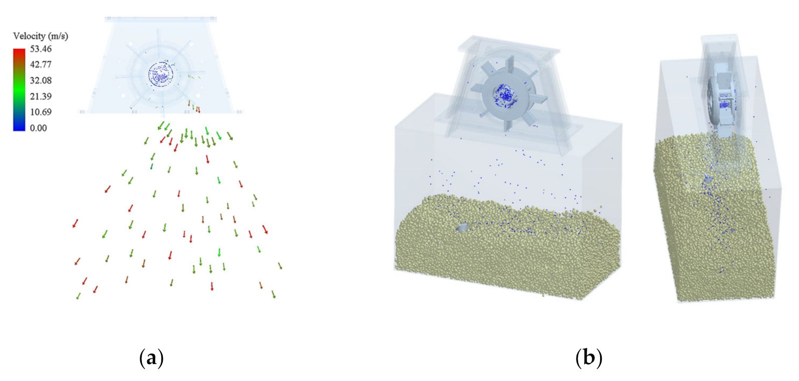
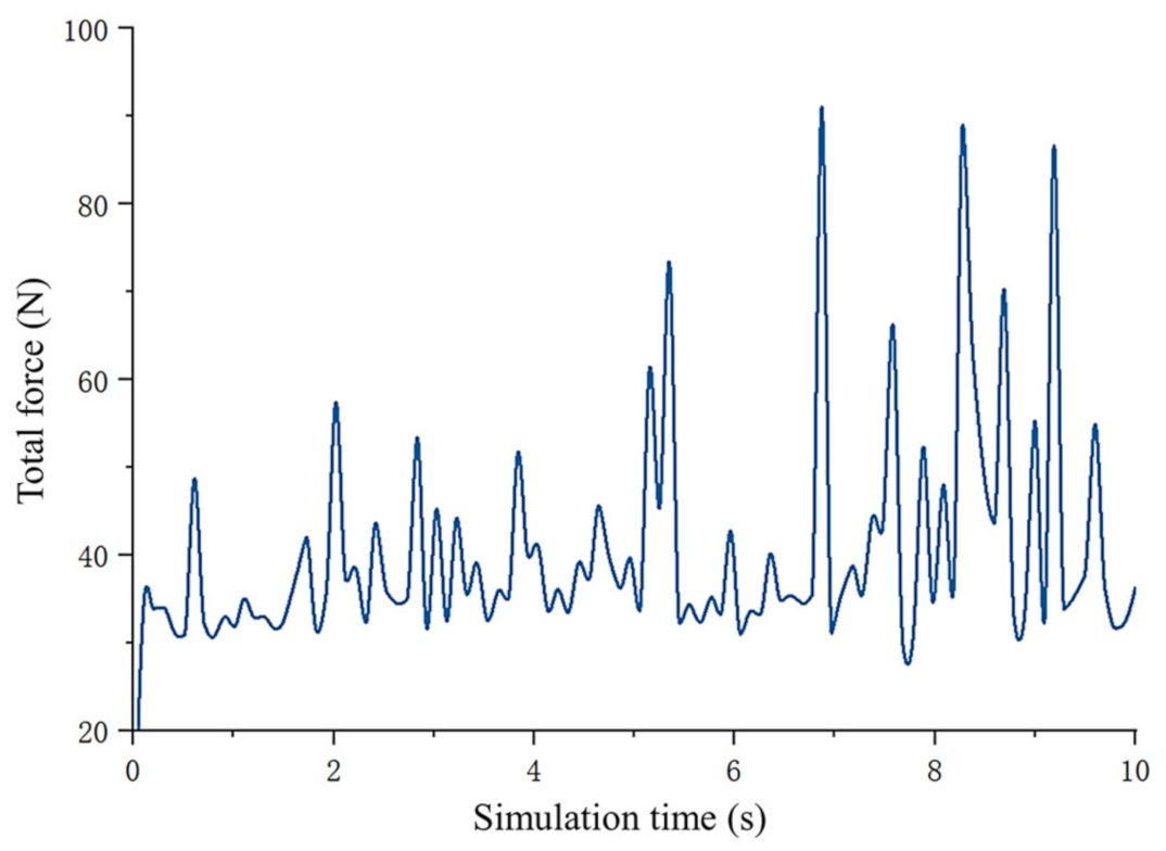
3.3. Numerical Simulation and Analysis

Due to the large number of particle contacts in the simulation model, a fixed time step of 20% was set to ensure the stability of the simulation. Without sacrificing the simulation results, the actual simulation time was minimized, the target storage time interval was set at 0.1 s. The grid size was three times the minimum particle radius, and the resulting total simulation time was 10 s. Figure 6a shows the velocity of some projectiles when they were ejected, which also shows that the projectiles can form a shot-blasting area in the lower square at a speed of 54.5 m/s after they are accelerated in the shot-blasting machine. Figure 6b is the shot-blasting effect diagram during the working process of the prototype. It can be noticed that the shot-blasting range can just cover the cross section of the treatment chamber. As a result, the top aggregates can be sufficiently shot blasted, and the shot will not directly impact the side wall of the chamber.
Figure 7 demonstrates the velocity of the coarse aggregates in the treatment chamber at a certain time. With the turning of the spiral blade, the aggregates can be evenly distributed along the circumference of the blade in the horizontal direction, and can be lifted from the bottom to the top in the vertical direction. After reaching the top, the aggregates will fall along the edge of the chamber. The combination of motion in two directions cycles the aggregates in the chamber, causing the aggregates in different locations to be processed by blasting, forming an enhanced grinding area between the two blades. Thus, all aggregates can be fully and evenly blasted and ground to realize the maximum stripping effect of the asphalt from the aggregate surface.
Under the action of shot blasting and the self-grinding of aggregates, aggregates will be subject to a comprehensive force, namely an asphalt-stripping force. Affected by this force, aged asphalt can fall off the aggregate surface. Figure 8 presents the total stripping force of coarse aggregates with respect to time in the simulation process.

4. Test of the Principle Prototype

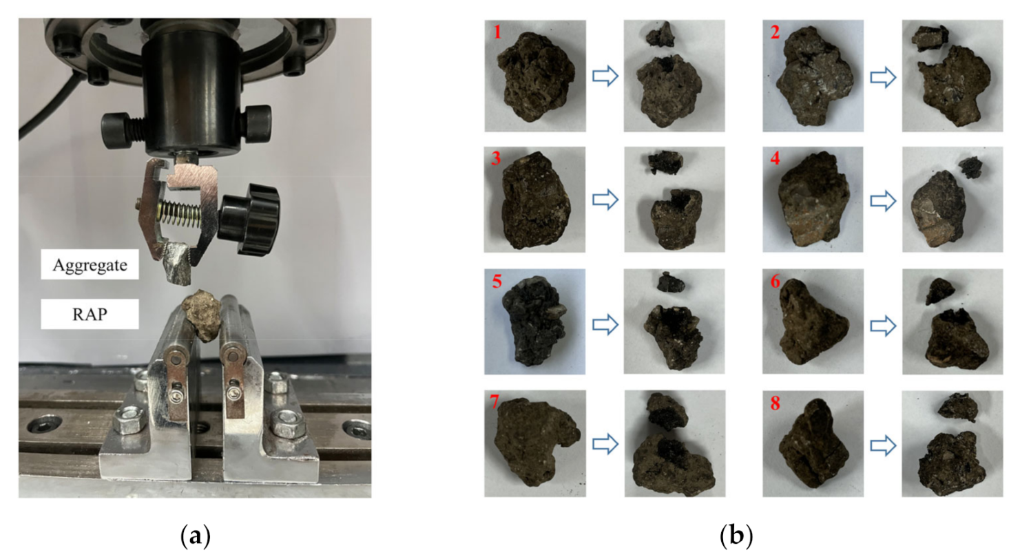
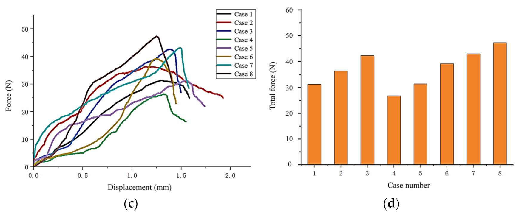
4.1. Mechanical Test of Single Particle Asphalt Stripping

In order to verify whether the aggregate stripping force obtained via simulation can meet the requirements of the force required for actual asphalt stripping, the WDM-100 electronic universal testing machine was applied to conduct a single particle asphalt-stripping test, as shown in Figure 9a. The aggregate and RAP were, respectively, fixed to the fixtures, and the load on the lower aggregate was controlled by the upper aggregate at a speed of 2 mm/min. The asphalt on the surface of the aggregate was stripped by the angular aggregate until the aged asphalt fell off the aggregate surface, and the corresponding deformation and failure load were recorded. The maximum value of the applied load during the measurement was the force required to strip the aged asphalt from the surface. A total of 8 groups of tests were conducted, all of which completed the stripping of aged asphalt from the aggregate surface, and the aggregate in the upper fixture did not break. Figure 9b depicts the aggregates before and after stripping for comparison.
According to the corresponding deformation and failure load recorded during the test, the force and displacement curves are drawn as shown in Figure 9c. Because the aggregates were composed of aggregates with different particle sizes and asphalt with different degrees of aging, they still had a certain viscosity and were not brittle materials. Therefore, the force and displacement curves were not smooth. Although the force and displacement curves for case 1 and 2 did not show a significant drop trend after the peak point, the maximum load measured could still be used to quantitatively evaluate the force required to strip asphalt. To compare the maximum load data obtained from tests with the simulation data, Figure 9d is depicted. It can be observed that the resultant force on the aggregates during the processing of the principle prototype is higher than the stripping force measured in the single particle mechanical test, but it is still far less than the crushing strength limit of aggregate. With the repeated treatment of various acting forces, the aggregate surface asphalt will eventually strip off, and it can be guaranteed that the principle prototype will be dedicated to the aggregate surface-asphalt-stripping treatment, rather than producing a large-scale crushing effect. Therefore, it was verified that the structure of the prototype was reasonable.

4.2. Treatment Process of the Principle Prototype

In addition to the initial design, a frequency conversion cabinet was added at one side of the principle prototype to realize the adjustment of the rotating speed of the spiral blade and the power of the shot-blasting machine, and a cyclone dust collector was installed at the rear of the prototype to reduce the dust during treatment. Figure 10 presents the 3D drawing and manufactured product of the principle prototype. The working process was as follows: the coarse aggregates were fed into the treatment chamber through the coarse aggregate entrance until they covered the spiral blades. Subsequently, the entrance of the cyclone dust collector was connected to the coarse aggregate entrance to reduce the dust. Then, the spindle motor and shot-blasting motor were started, and fine aggregates were added to the entrance of the shot-blasting machine at a uniform speed. Meanwhile, the fine aggregates were accelerated by the impeller of the shot-blasting machine and ejected towards the coarse aggregates at the top layer of the treatment chamber at high speeds. The aggregates were stirred by the spiral blades at the bottom, and the self-weight of the aggregates made them produce a comprehensive effect of extrusion, shearing and friction. As a result, the stripping of asphalt on the aggregate surface was realized. Because there is enough space above the aggregates, the aggregates will not be subject to pressure exceeding its strength limit, so the micro-damage fine treatment of the aggregate surface can be completed without large-scale crushing. During the operation of the prototype, the stripped asphalt and mineral powder (below 4.75 mm) fell into the guide plate through the sieve plate, and were discharged from the fine aggregate exit. After most of the asphalt on the surface of the coarse aggregates inside the treatment chamber was stripped, all motors were shut down, and the feeding of fine aggregates was stopped. The cover board was opened and the processed aggregates in the treatment chamber were taken out. So far, the fine asphalt stripping on the surface of aggregates was accomplished.

4.3. Test Scheme and Preparation

The controlled test was conducted based on the principle prototype, in which the mass of the coarse aggregates to be treated was 40 kg, and the projectile size and treatment duration were changed, respectively. The treatment effect of the prototype was evaluated by the changes in different indicators of the coarse aggregates before and after treatment. The specific test scheme is presented in Table 4.
According to the macroscopical structure and composition of coarse aggregates before and after treatment, the treatment effect indexes were mainly reflected in the change in surface morphology and asphalt content. The change in surface morphology can be observed directly by comparing the change in surface color, shape and composition of aggregates before and after treatment. To facilitate a targeted observation, some raw aggregates were dyed and marked before treatment. In addition, it was necessary to weigh the screened aggregates, calculate the mass loss ratio of coarse aggregates before and after treatment as the asphalt-stripping rate, and explore the asphalt-stripping situation under different test schemes. For the calculation formula, see Equation (12), where P is the asphalt-stripping rate, and m0 and m1 are the masses of coarse aggregates before and after treatment.
P = m 0 m 1 m 0

5. Results and Discussion

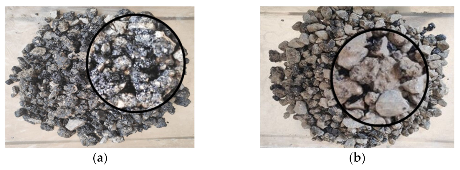
5.1. Change in Surface Morphology of Coarse Aggregates

A random sampling method was used to observe the treated coarse aggregates, and the comparison of surface morphology before and after treatment is demonstrated in Figure 11. Obviously, most of the coarse aggregates lost the black aged asphalt and exposed the gray rock surface, indicating that the stripping effect of asphalt attached to the aggregate surface was satisfactory. Moreover, through the comparison of the dyed and marked aggregates (as shown in Figure 12), it was found that the asphalt layer on the surface of the treated coarse aggregates had obvious grinding traces. The RAP composed of aggregates and aged asphalt were worn and broken, indicating the separation of aggregates and asphalt, which verifies the feasibility of the proposed stripping process.

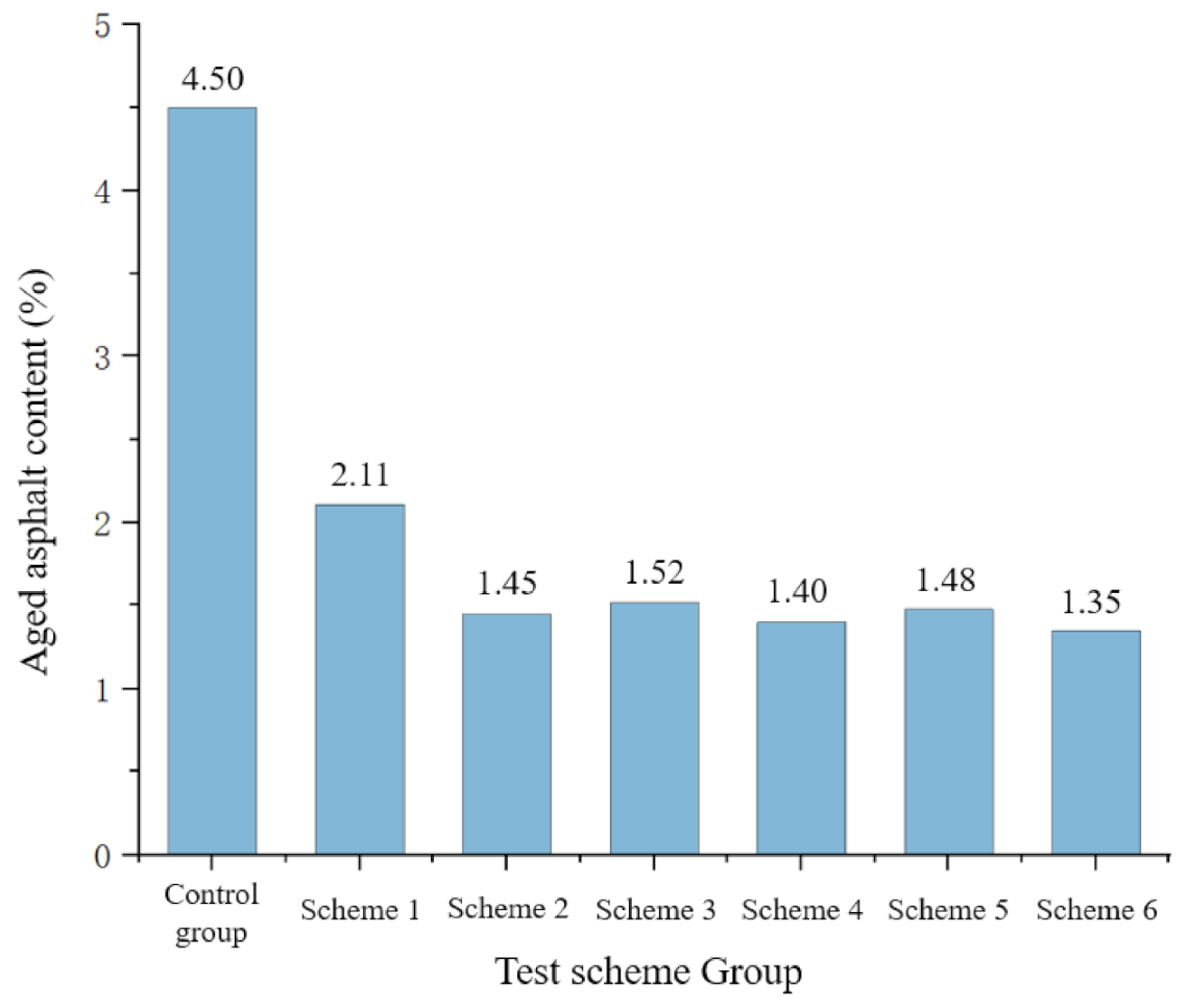
5.2. Changes in Asphalt Content of Coarse Aggregates

In order to further verify the asphalt-stripping effect of the principle prototype in the process of fine treatment, the treated coarse aggregates were weighed, and the stripping effect was quantitatively analyzed by the asphalt-stripping rate index. The asphalt-stripping rate of the principle prototype under different test schemes is tabulated in Table 5.
It can be concluded from Table 5 that the six groups of tests form four groups of controlled tests:
The comparison between Schemes 1 and 2, and Scheme 3 and 4, reveals that the asphalt-stripping rate increases with the increase in treatment time, regardless of whether the shot-blasting process is added. With the increase in treatment time, the time for aggregates to collide and strike each other increases, which can realize the more sufficient shedding of aged asphalt on the aggregate surface.
The comparison between Schemes 1 and 3, and Schemes 2 and 4, confirms that when the treatment time is the same, the surface treatment of coarse aggregates can be promoted by adding shot-blasting treatment, which can significantly increase the as-phalt-stripping rate. This is due to the fact that, on the basis of self-grinding of coarse aggregates, high-speed projectiles can have a strong impact on the surface of coarse aggregates. Under the dual effect, the aged asphalt on the surface of aggregate is stripped faster.
The comparison between Schemes 3 and 5, and Schemes 4 and 6, verifies that the asphalt-stripping effect is better when the projectiles size is 2.36–4.75 mm. Actually, the average mass of 2.36–4.75 mm aggregates is higher at the same flow rate, the kinetic energy is larger, and the impact on coarse aggregates is correspondingly greater. That is the reason why it has better asphalt-stripping effect.
Schemes 1 and 2 show that when the treatment time is increased without the shot blasting process, the asphalt-stripping rate can be increased by 22.47%; Scheme 3 shows that when shot blasting is adopted, the stripping rate after 30 min is close to Scheme 2, whose treatment time is 60 min. For Scheme 4, the treatment time is doubled compared to Scheme 3, but the asphalt-stripping efficiency is only increased by 9.5%, which indicates that the stripping rate will reach the stable stage faster with the action of shot blasting.
The combustion furnace method is applied to measure the residual aged asphalt content of the treated coarse aggregates, and the result is collected in Figure 13. With the untreated aggregates as the control group, the aged asphalt content is 4.5%. It can be found that the asphalt content of each group of coarse aggregates is significantly reduced after the treatment by the principle prototype. With the same treatment process, the longer the treatment time, the lower the asphalt content; with the same treatment time, the treatment effect is better when the projectiles size is 2.36–4.75 mm, while the treatment effect is relatively worse without shot blasting. This result is consistent with the trend of the asphalt-stripping ratio reflected in Table 5.

5.3. Particle Size Ratio of Each Grade

The processed coarse aggregates were collected and the screening test was conducted to obtain the particle size ratio of each grade. The result is shown in Figure 14. Compared with the control group, the proportion of raw aggregates with a particle size within 9.5–19 mm decreases, while the proportion of aggregates with a particle size within 4.75–9.5 mm increases, but the proportion of the overall particle size does not change much. This result proves that the principle prototype can guarantee the original gradation of coarse aggregates and avoid excessive refinement.

6. Conclusions

Based on surface cleaning technology and combined with theoretical analysis and simulation verification, this paper designs and tests an efficient micro-damage fine asphalt-stripping principle prototype, and studies the asphalt-stripping effect of this prototype with different processing schemes. The results are as follows:
(1)
The principle prototype with fine aggregate blasting and coarse aggregate self-grinding has a satisfactory treatment effect, which can realize the stripping of asphalt on the surface of coarse aggregates without damaging the grading of coarse aggregates. The reliability of the prototype is also preliminarily verified.
(2)
The shot-blasting effect and the self-grinding effect lead to satisfactory asphalt stripping. When the blasting process is not applied, the asphalt-stripping efficiency is low because only the self-grinding contributes. With both processes active, the asphalt content on the aggregate surface can reach the lowest achievable amount in the shortest time.
(3)
With the application of the blasting process, increasing the treatment time and projectile size can increase the asphalt-stripping rate and reduce the residual aged asphalt content on the aggregate surface. The effect of 2.36–5 mm projectiles and 60 min treatment is the best; the highest stripping rate can reach 41.5%, and the lowest asphalt content can be reduced to 1.35% after treatment. Considering that the energy consumption of 60 min treatment is doubled compared with a 30 min treatment, while the improvement of the treatment effect is limited, different process parameters should be selected according to the actual working conditions.
In addition, compared with purchasing new aggregate, the cost of processing the same quantity of RAP aggregate using the prototype can be saved by 42%, which is verified by actual energy consumption records. The stripped aged asphalt in RAP can significantly reduce chemical pollution from the production of recycled mixture. Therefore, the proposed method can realize the recycling of mineral resources under low-energy consumption, which has considerable economic and environmental benefits.
Due to the existence of aged asphalt, the addition of RAP will have a negative impact on the low-temperature cracking resistance, water stability, and fatigue performance of the mixture. Through tests, the asphalt on the surface of RAP can be dramatically reduced after the treatment with the proposed machine. The processed aggregate can achieve similar performance as the virgin aggregate after mixing with a little rejuvenator. Therefore, the existing problem can be effectively avoided and the performance of the asphalt mixture can be guaranteed in theory. The specific performance of the recycled asphalt mixture will be verified when the subsequent machine for production is designed.

Author Contributions

Conceptualization, L.Z.; methodology, L.L.; simulation support, M.W. and D.M.; validation, X.L.; formal analysis, S.W.; investigation, W.Z.; resources, X.H., data curation, J.Z.; writing—original draft preparation, L.Z.; writing—review and editing, L.L.; visualization, B.Z.; supervision, L.L.; project administration, Z.Y.; funding acquisition, L.L. All authors have read and agreed to the published version of the manuscript.

Funding

This research was funded by Transportation Technology Program of Shandong Province, grant number 2020B66; National Natural Science Foundation of China, grant number 52205484; China Postdoctoral Science Foundation, grant number 2020M682173; Natural Science Foundation of Shandong Province, grant number ZR2020QE166; Shandong Provincial Key Research and Development Program (Major Scientific and Technological Innovation Project) (2021CXGC010206).

Data Availability Statement

Not applicable.

Conflicts of Interest

The authors declare no conflict of interest.

References

  1. Al-Sabaeei, A.M.; Napiah, M.B.; Sutanto, M.H.; Alaloul, W.S.; Usman, A. A Systematic Review of Bio-Asphalt for Flexible Pavement Applications: Coherent Taxonomy, Motivations, Challenges and Future Directions. J. Clean. Prod. 2020, 249, 119357. [Google Scholar] [CrossRef]
  2. Rahman, M.T.; Hainin, M.R.; Bakar, W.A.W.A. Use of Waste Cooking Oil, Tire Rubber Powder and Palm Oil Fuel Ash in Partial Replacement of Bitumen. Constr. Build. Mater. 2017, 150, 95–104. [Google Scholar] [CrossRef]
  3. Hu, Y.; Si, W.; Kang, X.; Xue, Y.; Wang, H.; Parry, T.; Airey, G.D. State of the Art: Multiscale Evaluation of Bitumen Ageing Behaviour. Fuel 2022, 326, 125045. [Google Scholar] [CrossRef]
  4. Zhang, H.; Chen, Z.; Xu, G.; Shi, C. Evaluation of Aging Behaviors of Asphalt Binders through Different Rheological Indices. Fuel 2018, 221, 78–88. [Google Scholar] [CrossRef]
  5. Jiang, L.; Liu, Y. Recycle of Waste Asphalt Mixture. J. Northeast For. Univ. 2007, 35, 88–89. [Google Scholar] [CrossRef]
  6. Yaseen, G.; Alaloul, W.S.; Hafeez, I.; Qureshi, A.H. Shape Characterizing of Aggregates Produced through Different Crushing Techniques. Coatings 2021, 11, 1199. [Google Scholar] [CrossRef]
  7. Zaumanis, M.; Mallick, R.B. Review of Very High-Content Reclaimed Asphalt Use in Plant-Produced Pavements: State of the Art. Int. J. Pavement Eng. 2015, 16, 39–55. [Google Scholar] [CrossRef]
  8. Willis, J.R.; Marasteanu, M. National Cooperative Highway Research Program; Transportation Research Board; National Academies of Sciences, Engineering, and Medicine. In Improved Mix Design, Evaluation, and Materials Management Practices for Hot Mix Asphalt with High Reclaimed Asphalt Pavement Content; Transportation Research Board: Washington, DC, USA, 2013; p. 22554. ISBN 978-0-309-25913-2. [Google Scholar]
  9. Copeland, A. Reclaimed Asphalt Pavement in Asphalt Mixtures: State of the Practice; Report No. FHWA-HRT-11-021; Federal Highway Administration: Mclean, VA, USA, 2011. [Google Scholar]
  10. Raman, J.V.M.; Ramasamy, V. Various Treatment Techniques Involved to Enhance the Recycled Coarse Aggregate in Concrete: A Review. Mater. Today Proc. 2021, 45, 6356–6363. [Google Scholar] [CrossRef]
  11. Pandurangan, K.; Dayanithy, A.; Om Prakash, S. Influence of Treatment Methods on the Bond Strength of Recycled Aggregate Concrete. Constr. Build. Mater. 2016, 120, 212–221. [Google Scholar] [CrossRef]
  12. Ma, Y.; Ding, Y.; Zheng, K.; Polaczyk, P.; Zhang, M.; Xiao, R.; Huang, B. Effects of Immobilized RAP Binder on Asphalt-Aggregate Interaction and Performance of 100% Recycled Asphalt Mixtures. J. Mater. Civ. Eng. 2023, 35, 4023029. [Google Scholar] [CrossRef]
  13. Ma, Y.; Polaczyk, P.; Xiao, R.; Jiang, X.; Zhang, M.; Liu, Y.; Huang, B. Influence of Mobilized RAP Content on the Effective Binder Quality and Performance of 100% Hot In-Place Recycled Asphalt Mixtures. Constr. Build. Mater. 2022, 342, 127941. [Google Scholar] [CrossRef]
  14. Dimitriou, G.; Savva, P.; Petrou, M.F. Enhancing Mechanical and Durability Properties of Recycled Aggregate Concrete. Constr. Build. Mater. 2018, 158, 228–235. [Google Scholar] [CrossRef]
  15. Dilbas, H.; Çakır, Ö.; Atiş, C.D. Experimental Investigation on Properties of Recycled Aggregate Concrete with Optimized Ball Milling Method. Constr. Build. Mater. 2019, 212, 716–726. [Google Scholar] [CrossRef]
  16. Babu, V.S.; Mullick, A.K.; Jain, K.K.; Singh, P.K. Strength and Durability Characteristics of High-Strength Concrete with Recycled Aggregate-Influence of Processing. J. Sustain. Cem. -Based Mater. 2015, 4, 54–71. [Google Scholar] [CrossRef]
  17. Zhao, S.; Liu, H. Influence Evaluation of Shot Blasting Technology on Skid Resistance of Asphalt Pavement. Maint. Constr. Mach. 2015, 32, 76–79. [Google Scholar] [CrossRef]
  18. Kalala, J.T.; Breetzke, M.; Moys, M.H. Study of the Influence of Liner Wear on the Load Behaviour of an Industrial Dry Tumbling Mill Using the Discrete Element Method (DEM). Int. J. Miner. Process. 2008, 86, 33–39. [Google Scholar] [CrossRef]
  19. Ren, T.; Li, Z.; Liu, C.; Li, Y.; He, X. Simulation of Tower Mill Analysis Based on Discrete Element Method. China Powder Sci. Technol. 2016, 22, 88–91. [Google Scholar] [CrossRef]
  20. Choi, D.; Kim, T.; Yang, C.; Nam, J.; Park, J. Discrete Element Method and Experiments Applied to a New Impeller Blade Design for Enhanced Coverage and Uniformity of Shot Blasting. Surf. Coat. Technol. 2019, 367, 262–270. [Google Scholar] [CrossRef]
  21. Zhang, C.; Xu, S.; Liu, J.; Ma, Y. Comprehensive Clustering-Based Topology Optimization for Connectable Multi-Scale Additive Manufacturing Structures. Addit. Manuf. 2022, 54, 102786. [Google Scholar] [CrossRef]
  22. Zhang, C.; Wu, T.; Xu, S.; Liu, J. Multiscale Topology Optimization for Solid–Lattice–Void Hybrid Structures through an Ordered Multi-Phase Interpolation. Comput. -Aided Des. 2023, 154, 103424. [Google Scholar] [CrossRef]
  23. Jiang, P.; Ding, K. Analysis of Personalized Production Organizing and Operating Mechanism in a Social Manufacturing Environment. Proc. Inst. Mech. Eng. Part B J. Eng. Manuf. 2018, 232, 2670–2676. [Google Scholar] [CrossRef]
  24. Jiang, P.; Leng, J.; Ding, K.; Gu, P.; Koren, Y. Social Manufacturing as a Sustainable Paradigm for Mass Individualization. Proc. Inst. Mech. Eng. Part B J. Eng. Manuf. 2016, 230, 1961–1968. [Google Scholar] [CrossRef]
  25. Ji, X.; Li, J.; Zou, H.; Hou, Y.; Chen, B.; Jiang, Y. Multi Scale Investigation on the Failure Mechanism of Adhesion between Asphalt and Aggregate Caused by Aging. Constr. Build. Mater. 2020, 265, 120361. [Google Scholar] [CrossRef]
  26. Fang, Y.; Zhang, Z.; Shi, J.; Yang, X.; Li, X. Insights into Permeability of Rejuvenator in Old Asphalt Based on Permeation Theory: Permeation Behaviors and Micro Characteristics. Constr. Build. Mater. 2022, 325, 126765. [Google Scholar] [CrossRef]
  27. Sinnott, M.D.; Cleary, P.W.; Morrison, R.D. Is Media Shape Important for Grinding Performance in Stirred Mills? Miner. Eng. 2011, 24, 138–151. [Google Scholar] [CrossRef]
  28. Daraio, D.; Villoria, J.; Ingram, A.; Alexiadis, A.; Stitt, E.H.; Marigo, M. Investigating Grinding Media Dynamics inside a Vertical Stirred Mill Using the Discrete Element Method: Effect of Impeller Arm Length. Powder Technol. 2020, 364, 1049–1061. [Google Scholar] [CrossRef]
  29. Hensel, J.; Eslami, H.; Nitschke-Pagel, T.; Dilger, K. Fatigue Strength Enhancement of Butt Welds by Means of Shot Peening and Clean Blasting. Metals 2019, 9, 744. [Google Scholar] [CrossRef]
  30. Zhang, D.; Whiten, W.J. An Efficient Calculation Method for Particle Motion in Discrete Element Simulations. Powder Technol. 1998, 98, 223–230. [Google Scholar] [CrossRef]
  31. Zhang, D.; Whiten, W.J. A New Calculation Method for Particle Motion in Tangential Direction in Discrete Element Simulations. Powder Technol. 1999, 102, 235–243. [Google Scholar] [CrossRef]
  32. Ucgul, M.; Fielke, J.M.; Saunders, C. Three-Dimensional Discrete Element Modelling of Tillage: Determination of a Suitable Contact Model and Parameters for a Cohesionless Soil. Biosyst. Eng. 2014, 121, 105–117. [Google Scholar] [CrossRef]
  33. Carreau, P.J.; Bousmina, M.; Bonniot, F. The Viscoelastic Properties of Polymer-Modified Asphalts. Can. J. Chem. Eng. 2000, 78, 495–503. [Google Scholar] [CrossRef]
  34. Chen, J.S.; Zeng, L.; Yin, J. Discrete Element Method (DEM) Analyses of Hot-Mix Asphalt (HMA) Mixtures Compaction and Internal Structure. AMR 2013, 639–640, 1287–1294. [Google Scholar] [CrossRef]
  35. Bharadwaj, R.; Ketterhagen, W.R.; Hancock, B.C. Discrete Element Simulation Study of a Freeman Powder Rheometer. Chem. Eng. Sci. 2010, 65, 5747–5756. [Google Scholar] [CrossRef]
Figure 1. Structure of RAP and diffusion effect of rejuvenator on aged asphalt surface.
Machines 11 00367 g001
Figure 2. Structure and working principle. (a) Vertical shaft spiral mixing structure; (b) shot-blasting machine.
Machines 11 00367 g002
Figure 3. Explosion view of the principle prototype.
Machines 11 00367 g003
Figure 4. Model of particles. (a) Projectile model; (b) coarse aggregate model.
Machines 11 00367 g004
Figure 5. Simulation model of the principle prototype.
Machines 11 00367 g005
Figure 6. Image of simulation. (a) Velocity of the projectiles; (b) shot-blasting effect.
Machines 11 00367 g006
Figure 7. Velocity of the coarse aggregates in the treatment chamber. (a) Overall velocity of aggregates; (b) X-axis view of aggregate velocity; (c) Y-axis view of aggregate velocity; (d) Z-axis view of aggregate velocity.
Machines 11 00367 g007
Figure 8. The total force curve of coarse aggregates.
Machines 11 00367 g008
Figure 9. The stripping test of a single particle asphalt. (a) Test configuration; (b) aggregate comparison before and after asphalt stripping; (c) force and displacement curve of 8 tests; (d) total stripping force in 8 tests.
Machines 11 00367 g009aMachines 11 00367 g009b
Figure 10. A 3D drawing and manufactured product of the principle prototype.
Machines 11 00367 g010
Figure 11. Surface morphology of coarse aggregates before and after treatment. (a) Surface color of coarse aggregates before treatment; (b) surface color of coarse aggregates after treatment.
Machines 11 00367 g011
Figure 12. Comparison of dyed aggregates before and after treatment.
Machines 11 00367 g012
Figure 13. Asphalt content of coarse aggregates with different treatments.
Machines 11 00367 g013
Figure 14. Proportion changes in different particle sizes with different treatments.
Machines 11 00367 g014
Table 1. Physical property parameters of aggregate and steel.
Material TypePoisson’s RatioShear Modulus (Pa)Density (kg/m3)
Aggregate0.252.3 × 10102700
Steel0.37 × 10107850
Table 2. Contact relation parameters between different materials.
Relation of ContactCoefficient of RecoveryCoefficient of Static FrictionCoefficient of Sliding Friction
Aggregate–Aggregate0.100.600.24
Aggregate–Steel0.100.800.24
Table 3. Aggregate grading parameters.
Specification of Aggregate (mm)Aggregate Grade Ratio (%)
4.75–9.530.57
9.5–13.223.65
13.2–1629.66
16–26.516.12
Table 4. Test scheme.
SchemeCoarse Aggregates Mass/kgProjectiles Size/mmProcessing Time/min
140030
240060
3400–4.7530
4400–4.7560
5402.36–4.7530
6402.36–4.7560
Table 5. The stripping rate of the principle prototype with different treatment methods.
Schemem0/kgProjectiles Size/mmProcessing Time/minm1/kgP/%
14003028.4528.88
24006025.1037.25
3400–4.753025.4036.50
4400–4.756023.9040.25
5402.36–4.753025.0037.50
6402.36–4.756023.4041.50
Disclaimer/Publisher’s Note: The statements, opinions and data contained in all publications are solely those of the individual author(s) and contributor(s) and not of MDPI and/or the editor(s). MDPI and/or the editor(s) disclaim responsibility for any injury to people or property resulting from any ideas, methods, instructions or products referred to in the content.

