

An Autonomous Maze-Solving Robotic System Based on an Enhanced Wall-Follower Approach

Abstract
:1. Introduction
- Reviewing the recently developed wall-follower maze-solving robotic systems.
- Designing and implementing a maze-solving robotic system by employing a modified wall-follower method.
- Validating the implemented wall follower system through different maze environments by conducting real experiments using different maze structures.
- Comparing the obtained results from the modified wall-follower method with three different maze-solving algorithms.
2. Related Works
3. Modified Wall-Follower Solver Robot System
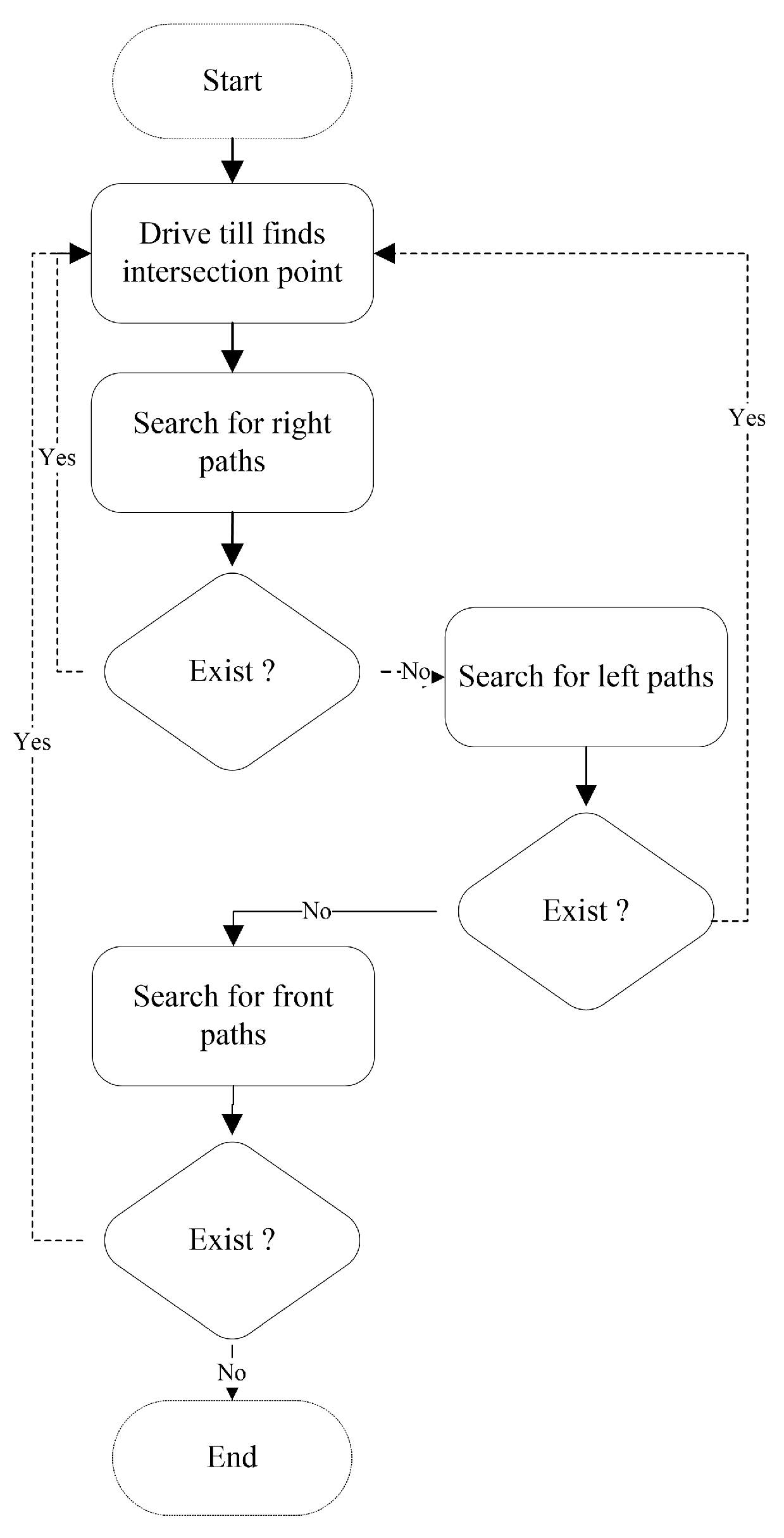
| Algorithm 1: The modified wall-follower method |
| 1: let be the solver mobile 2: let be the default direction value at the source point 3: let ( be the 2D coordinates for a point 4: let ( be the 2D coordinates for the destination point 5: let be the node in the maze area 5: let be the list of nodes in the maze area 5: let be the list of coordinates that traveled through 6: let ( be the 2D coordinates for the solver robot 7: while ( ( != ( 8: { moves in the maze area until it finds an intersection point ( 9: if ( then 10: rotate_180() 11: else add ( to } 12: end |
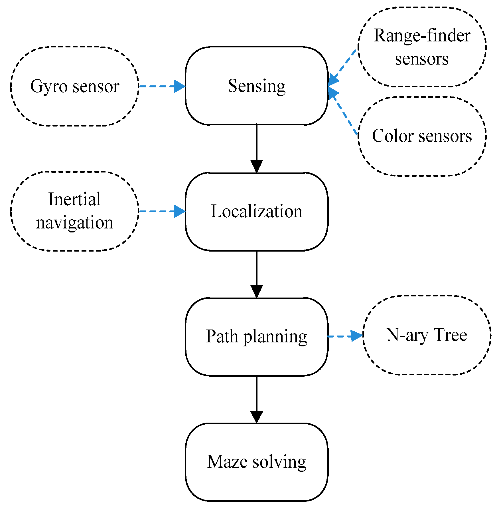
3.1. Sensing
| Algorithm 2: Auto Balance Function |
| 1: let be the rotation value obtained from the rotation sensor, where (180 > Sd > −180)
2: let SR be the solver robot 3: let be the default rotation value at the start point 4: while ( != 0) 5: { if ( < 0) then 6: else } 7: end |
3.2. Localization
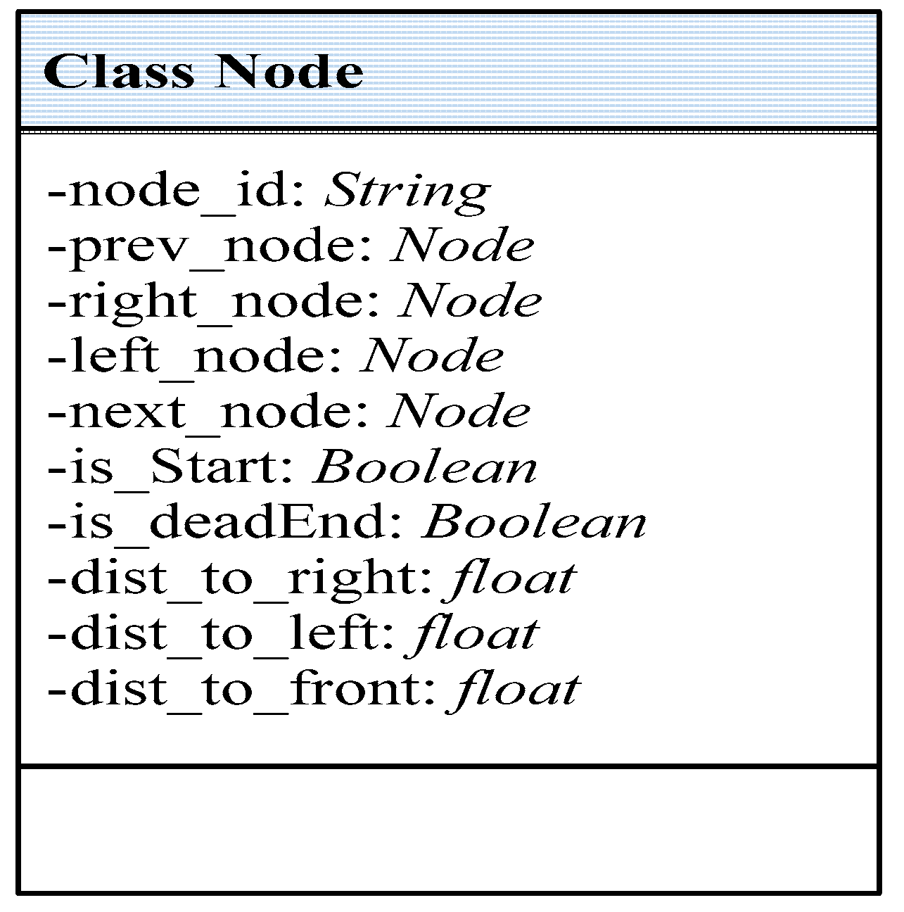
3.3. Path Planning
3.4. Maze Solving
4. Experimental Results
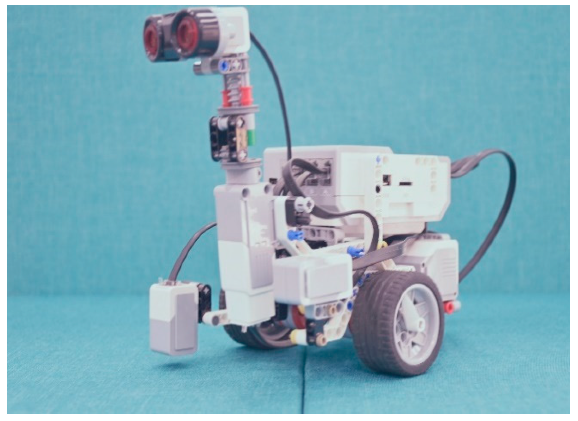
4.1. Expeirment Testbed
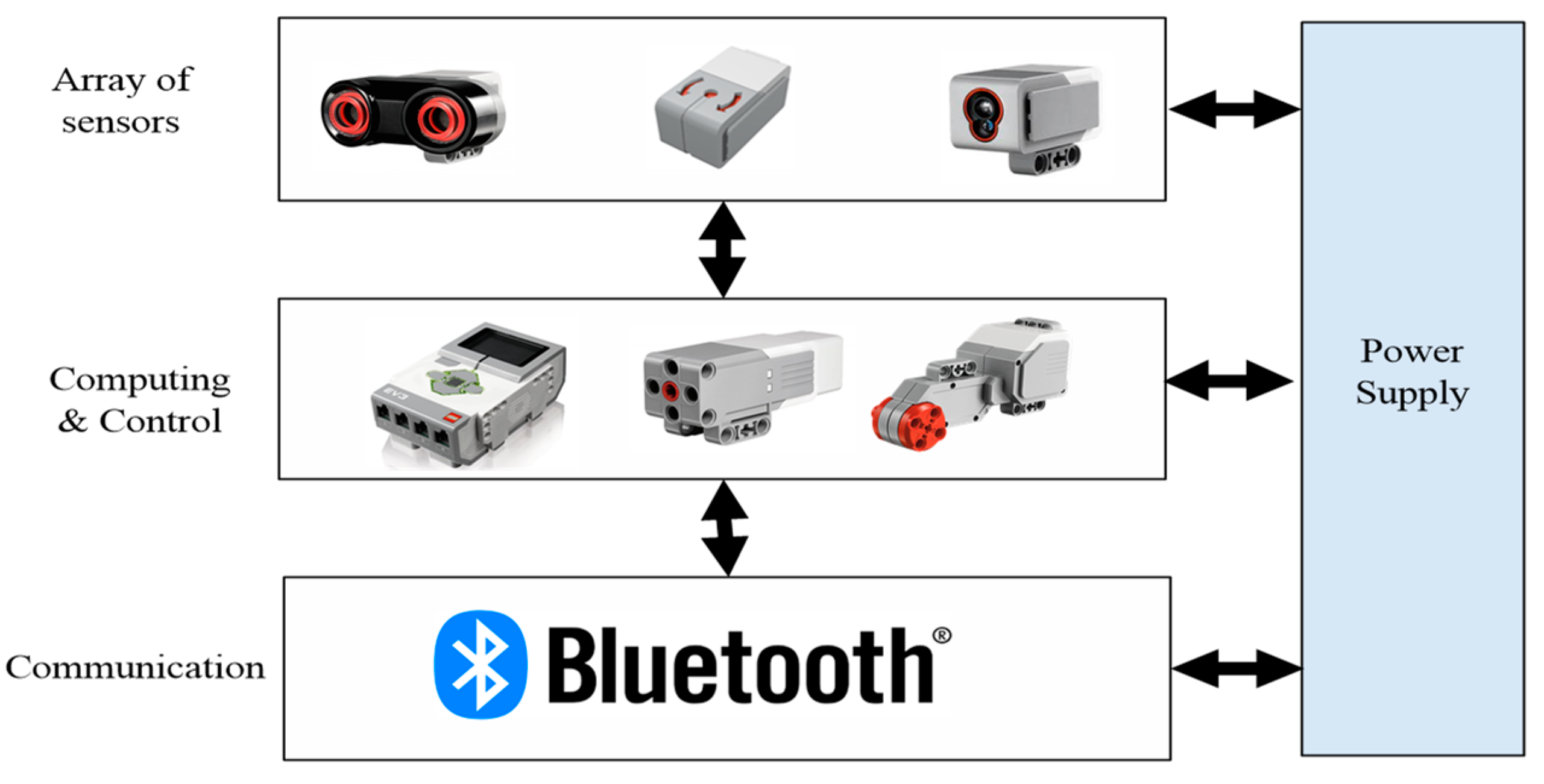
- Sensing unit: includes four different sensors that are required to sense the solver robot’s surrounding environment, including: ultrasonic, gyro, color, and inertial navigation sensors. Table 1 presents the general specifications for the ultrasonic sensor. The specifications for the gyro sensor are shown in Table 2, whereas Table 3 presents the specifications for the color sensor, and finally, the specifications for the inertial sensor are presented in Table 4.
- Computing and control unit: this collects sensed data from onboard sensors, processes the data, and makes suitable decisions accordingly.
- Communication unit: this includes exchanging the processed data between the solver robot and the GUI located in the computer unit.
- Power supply unit: this involves feeding the units mentioned above with the required energy.

| Parameter | Value |
|---|---|
| Distance measurement | 0–255 cm |
| Accuracy | +/−1 cm |
| Frequency | 40 KHz |
| Beam angle | 90 degree |
| Parameter | Value |
|---|---|
| Maximum rotation speed | 440 degree/second |
| Accuracy | +/−3 degrees |
| Control unit | 8-bit microcontroller |
| Frequency | 1 KHz |
| Parameter | Value |
|---|---|
| Sensitivity | 900 nm |
| Frequency | 1 KHz |
| Reading distance | 0.5–1.5 cm |
| Sensor output | 0–100 |
| Parameter | Value |
|---|---|
| Resolution | 1 count/degree |
| Rotation speed | 175 RPM |
| Power consumption | 60 mA |
| Parameter | Value |
|---|---|
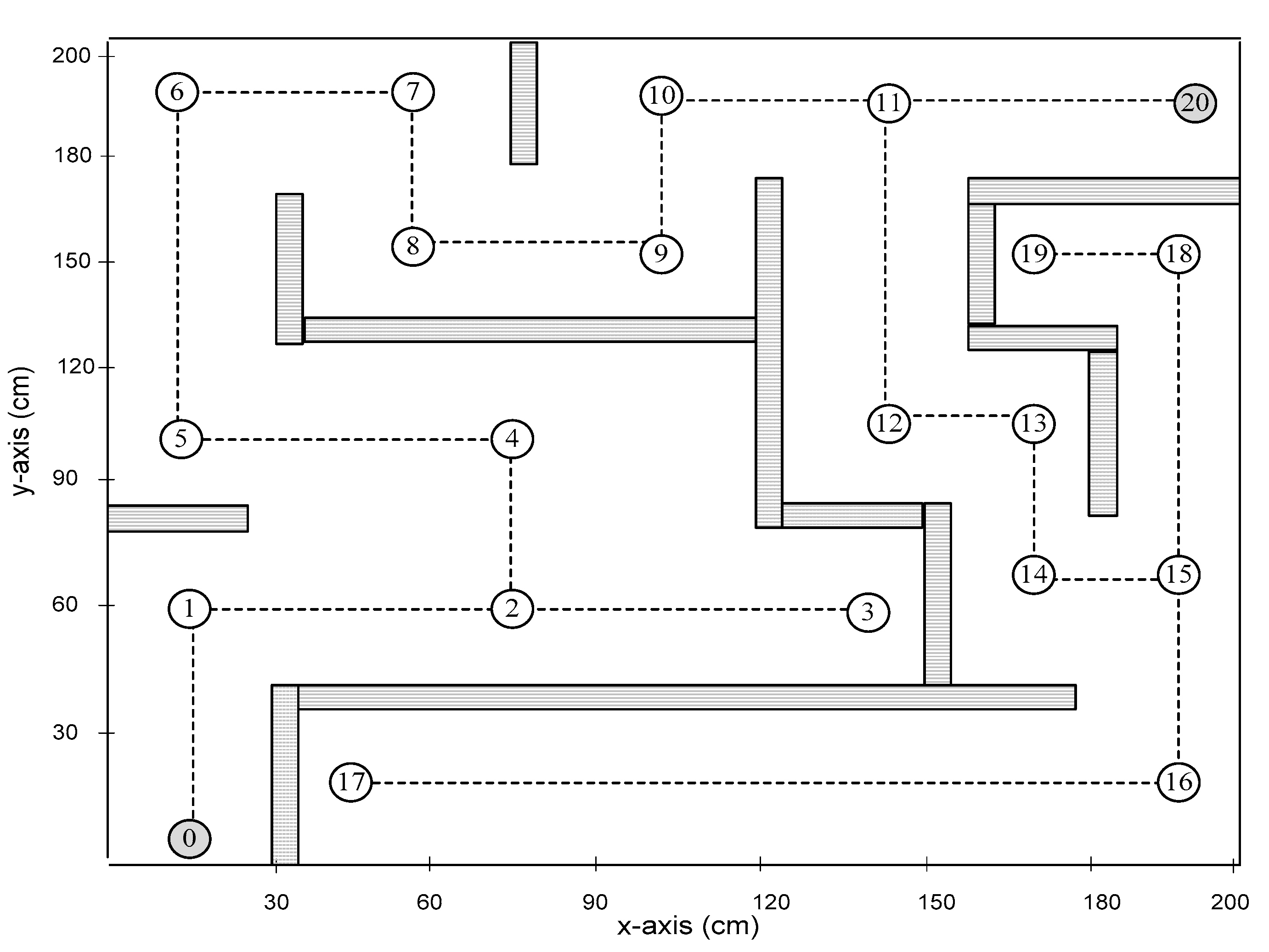
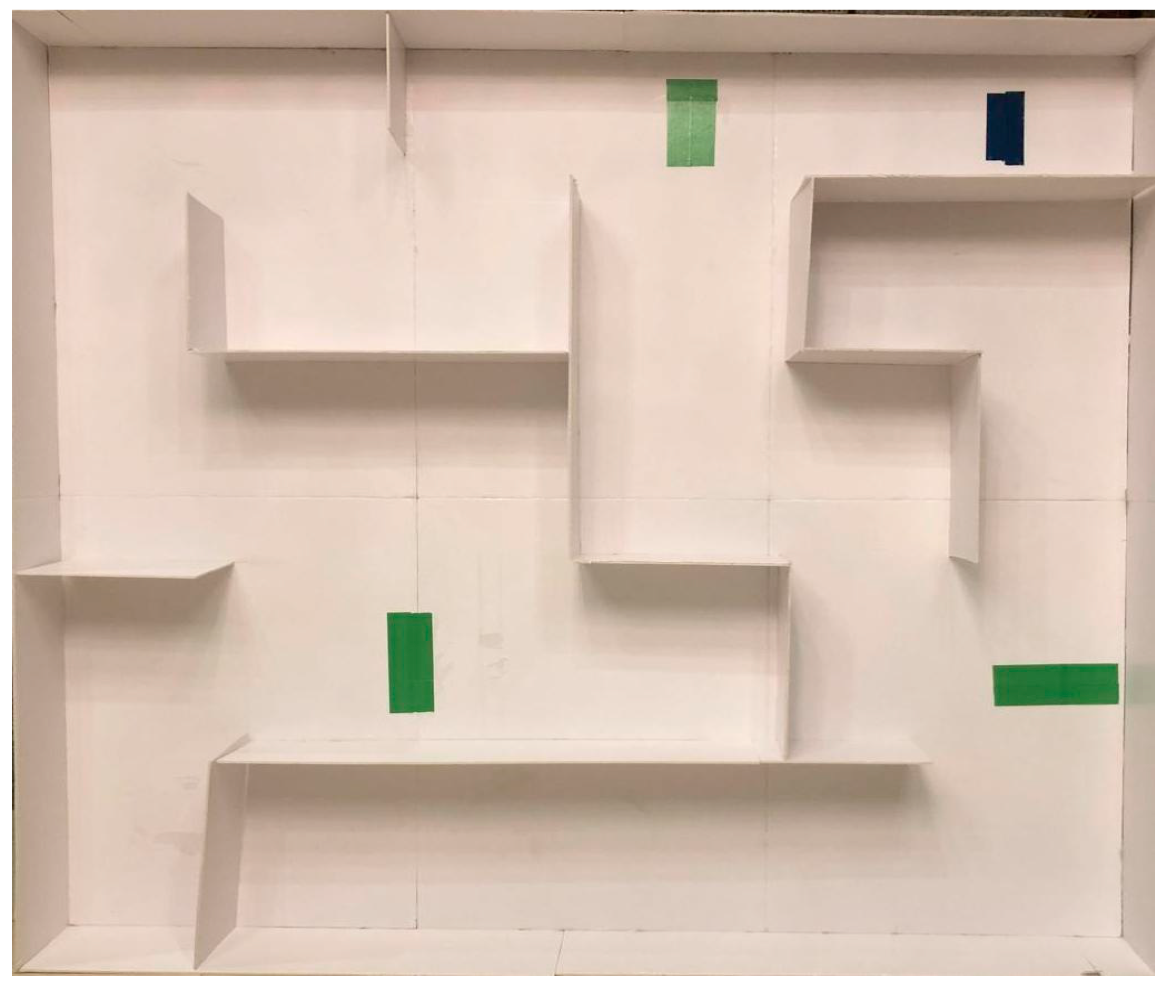
| Maze area | 2D (200 × 200) cm |
| Robot platform | Lego EV3 |
| Robot speed | 0.05 m/s |
| # of intersections | 3 |
| # of maze layouts | 3 |
| Ultrasonic range | 100 cm |
| Green label | An intersection point |
| Black label | Destination point |
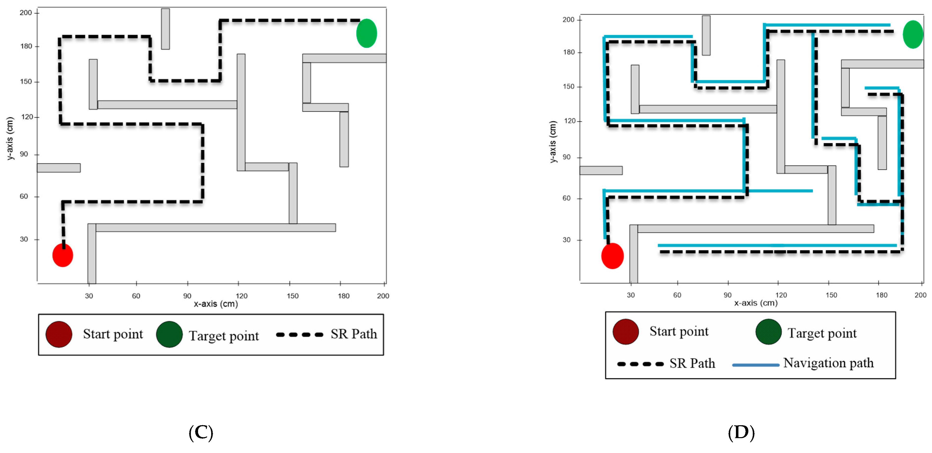
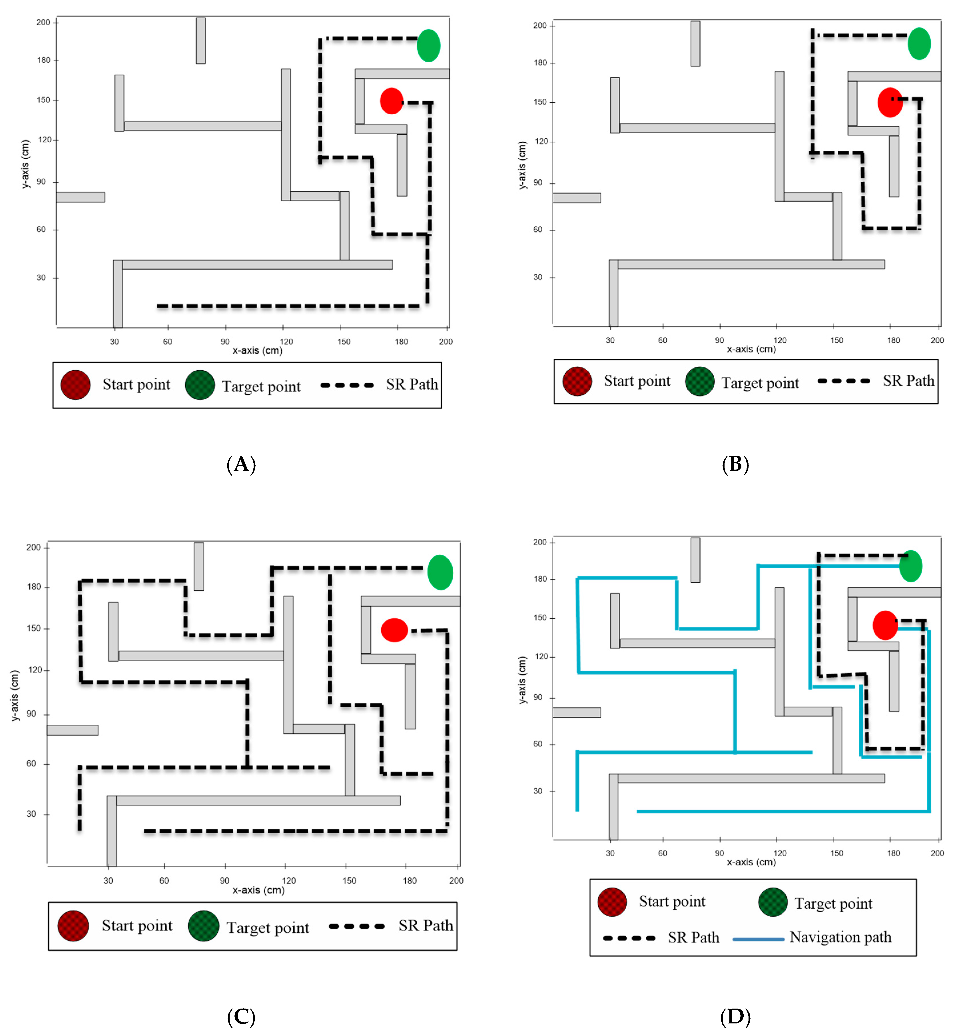
4.2. Results
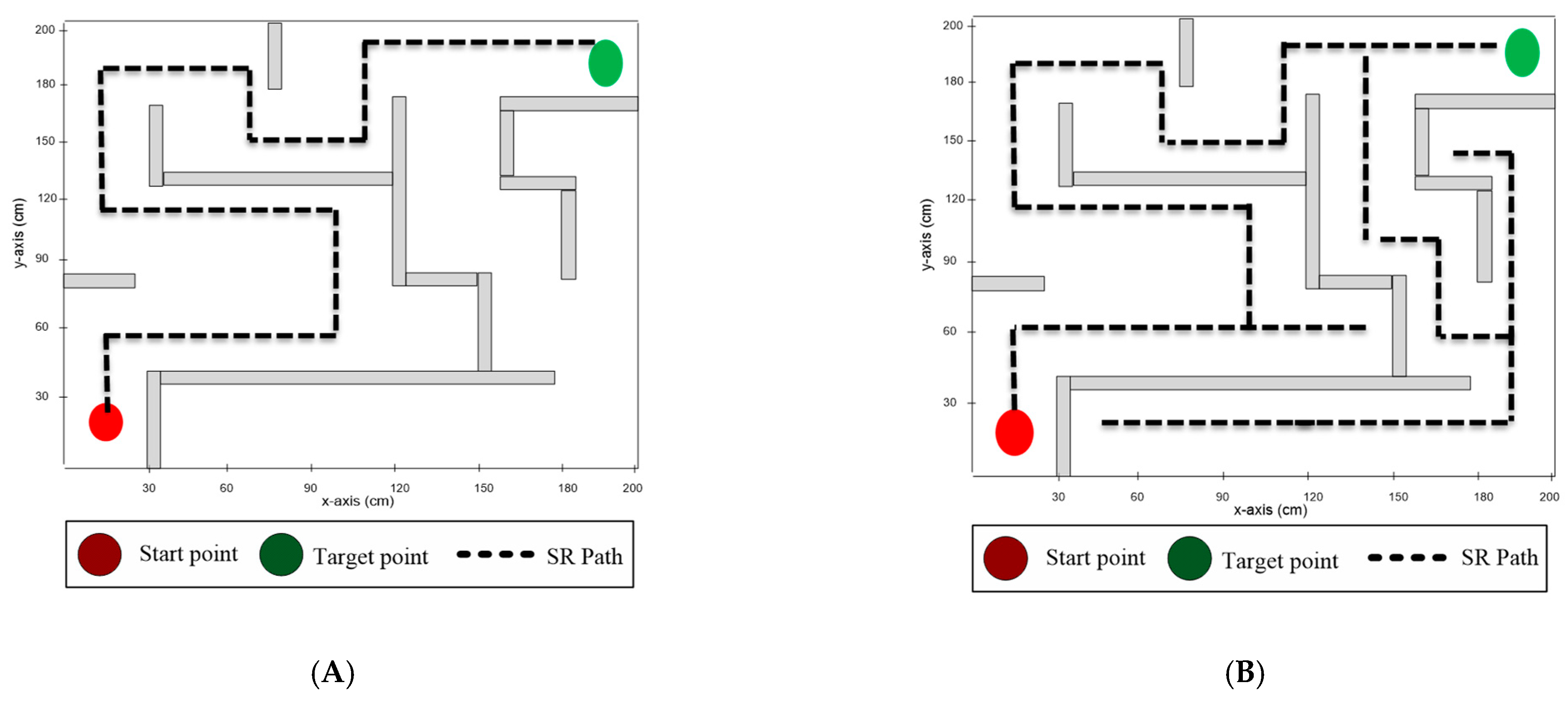
- Average time to solve the maze: this refers to the total time (in minutes) required to solve the maze, i.e., the time required for the solver robot to travel from the start point to the destination point. Average time depended on the maze solving algorithm and the taken path to reach the destination point.
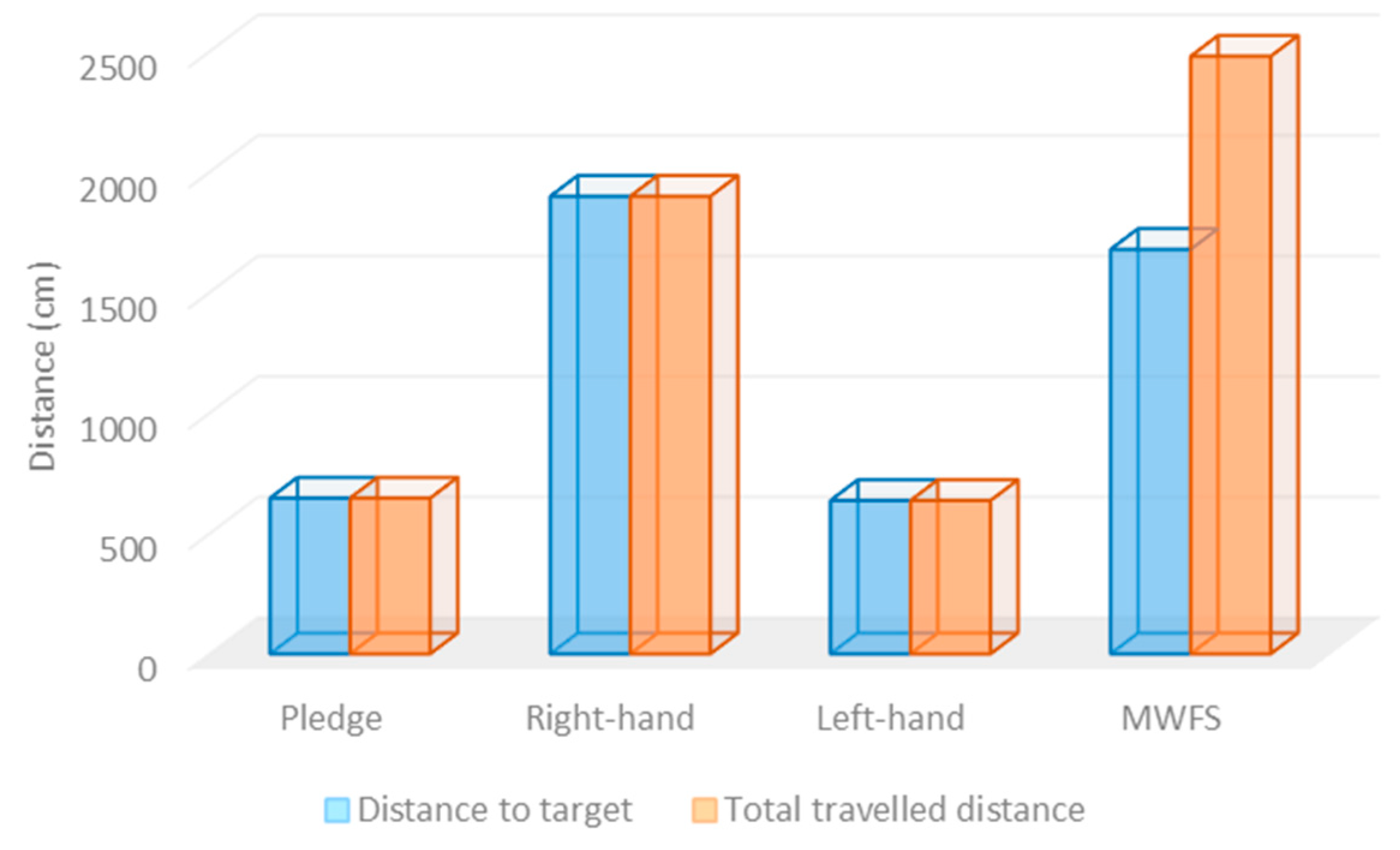
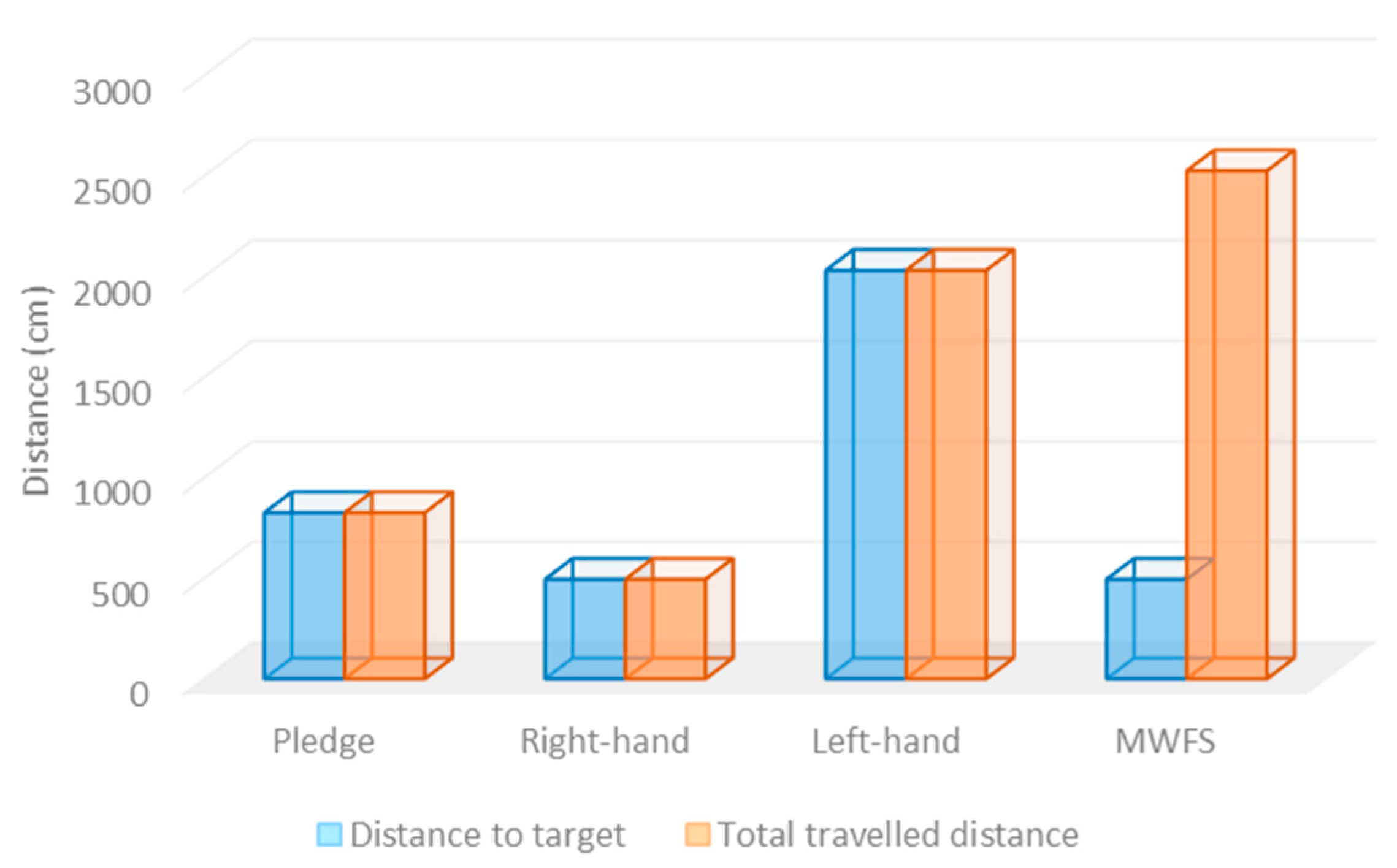
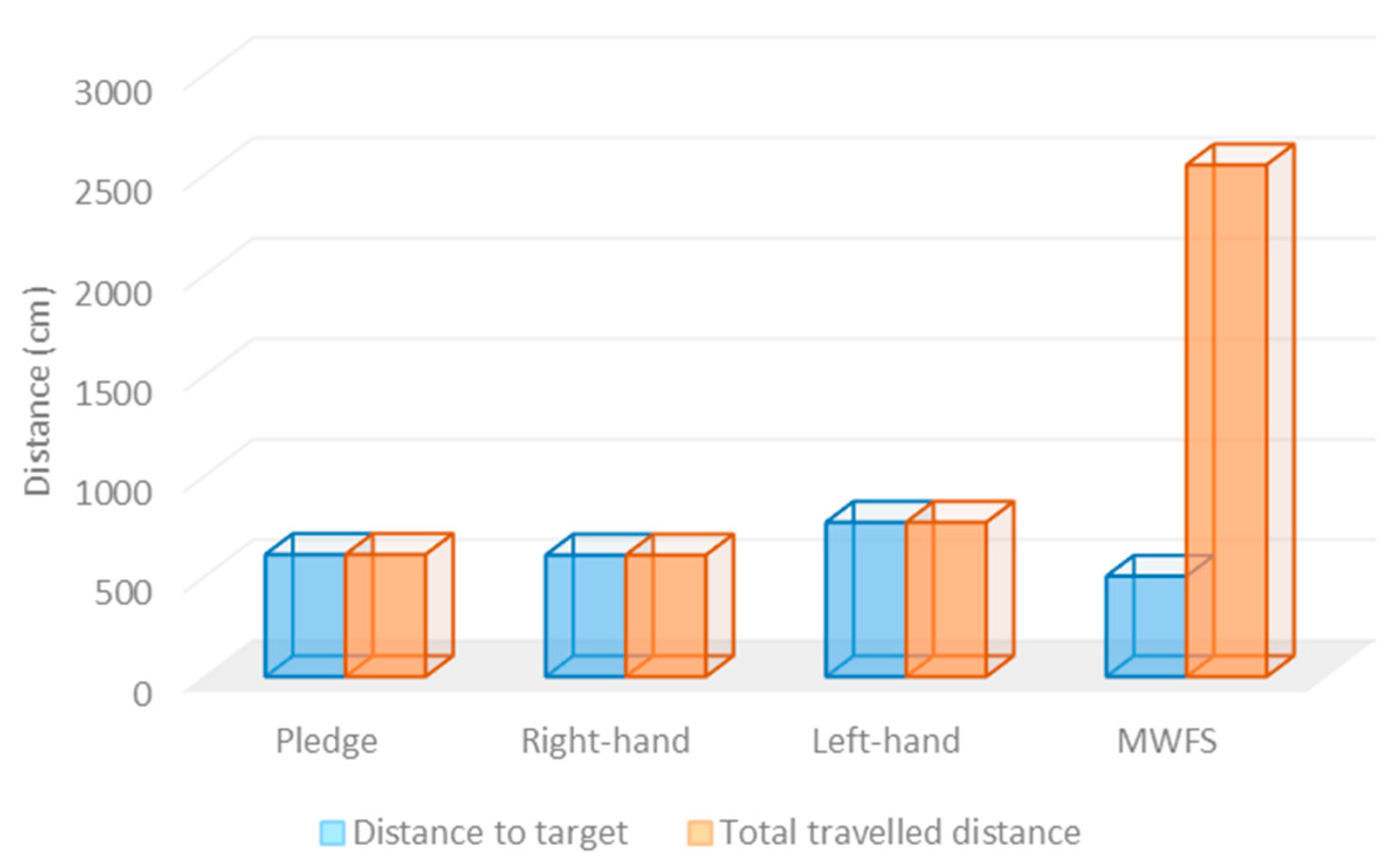
- Distance to target point: this refers to the total distance (in centimeters) traveled by the solver robot from the start point to the destination point.
- Total distance traveled in the maze: this indicates the total distance (in centimeters) traveled by the solver robot through the maze area.
- Number of visited paths: this refers to the total number of paths that the solver robot visited during the navigation process, i.e., the path from the source (initial) point to the destination point.
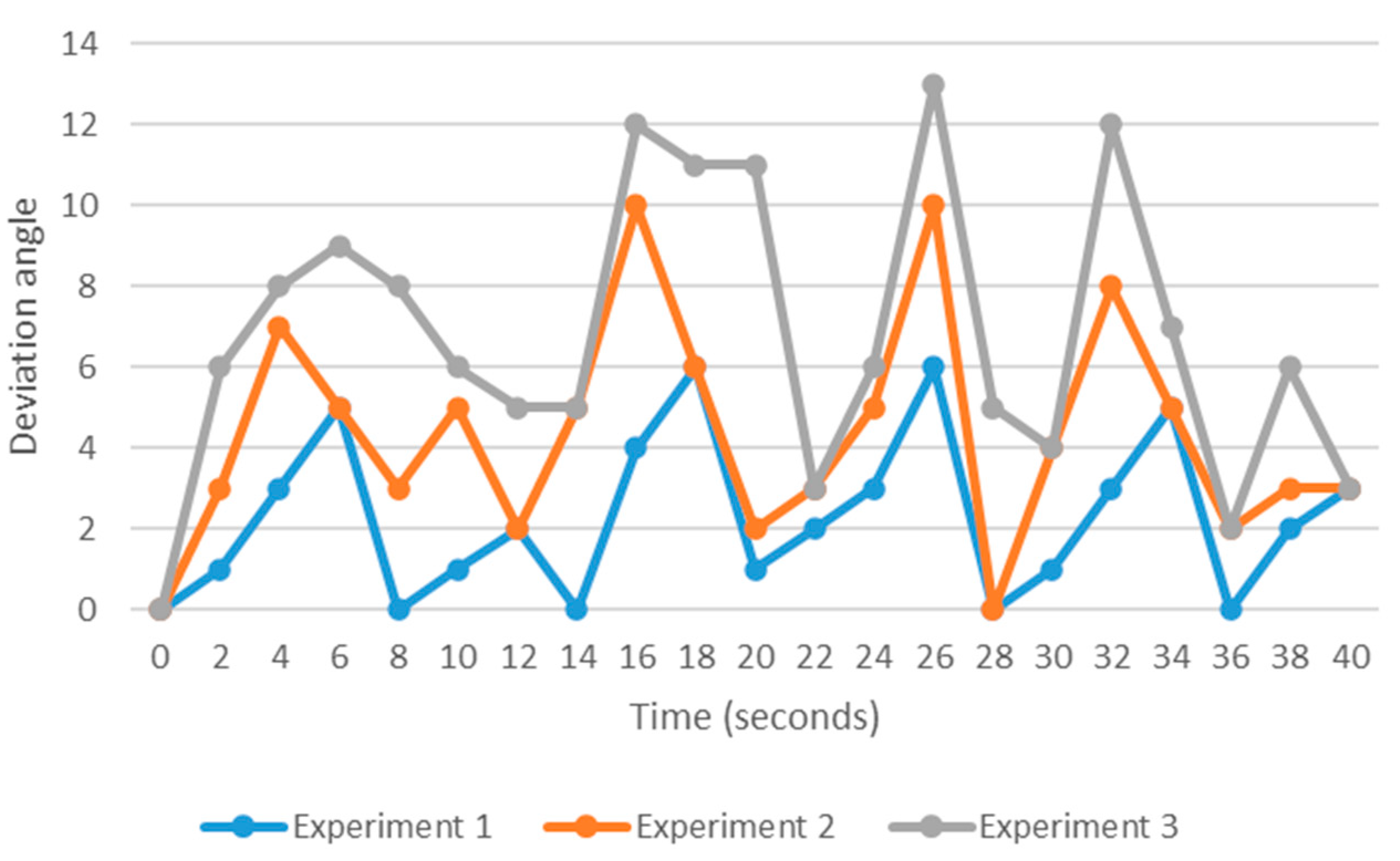
- Robot deviation: this estimates the deviation angle for the maze-solver robot while traveling between any two points in the maze area.
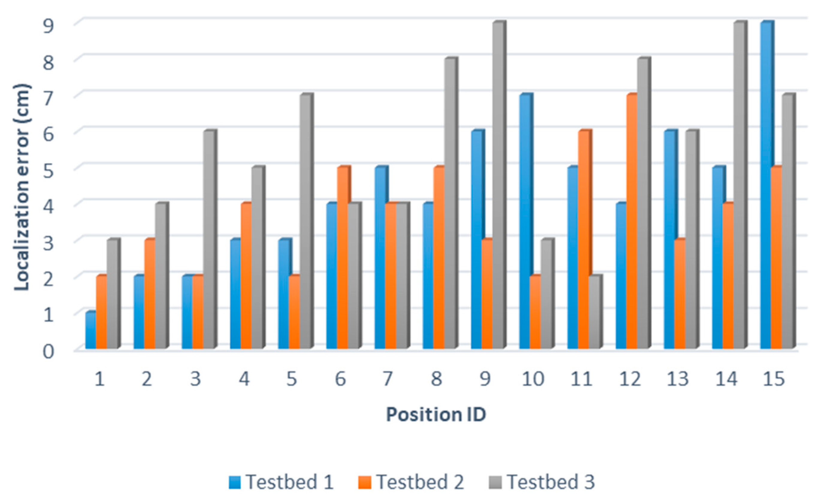
- Robot positioning accuracy: this refers to the measurement of the difference between the estimated location of the solver robot and the real robot’s location.
5. Discussion
- Maze solving algorithm: this refers to the algorithm that was employed to solve the maze area.
- Sensors: this refers to the arrays of sensors that were employed to achieve the navigation task.
- Experiment testbed: this refers to the type of validation testbed that was used to validate the maze-solving robotic system.
- Ability to find out the shortest path: this refers to the robot’s ability to explore all the existing paths between the start and the destination points and hence determine the robot’s ability to find out the shortest path possible.
- The developed maze-solver robot system solves the infinite loop issues that exist in the recently developed wall-follower systems.
- The developed MWFS can explore all possible paths in the maze area, and hence, MWFS is able to find out all the possible paths between the initial and the destination points.
6. Conclusions
Author Contributions
Funding
Data Availability Statement
Conflicts of Interest
References
- Gul, F.; Rahiman, W.; Nazli Alhady, S.S. A comprehensive study for robot navigation techniques. Cogent Eng. 2019, 6, 1632046. [Google Scholar] [CrossRef]
- Pandey, A.; Pandey, S.; Parhi, D.R. Mobile robot navigation and obstacle avoidance techniques: A review. Int. Rob. Auto. J. 2017, 2, 00022. [Google Scholar] [CrossRef]
- Wyard-Scott, L.; Meng, Q.H. A potential maze solving algorithm for a micro mouse robot. In Proceedings of the IEEE Pacific Rim Conference on Communications, Computers, and Signal Processing, Victoria, BC, Canada, 17–19 May 1995; IEEE: Piscataway, NJ, USA, 1995; pp. 614–618. [Google Scholar]
- Coufal, P.; Hubálovský, Š.; Hubálovská, M. Application of Basic Graph Theory in Autonomous Motion of Robots. Mathematics 2021, 9, 919. [Google Scholar] [CrossRef]
- Zhang, H.Y.; Lin, W.M.; Chen, A.X. Path planning for the mobile robot: A review. Symmetry 2018, 10, 450. [Google Scholar] [CrossRef]
- Tullu, A.; Endale, B.; Wondosen, A.; Hwang, H.Y. Machine learning approach to real-time 3D path planning for autonomous navigation of unmanned aerial vehicle. Appl. Sci. 2021, 11, 4706. [Google Scholar] [CrossRef]
- Tirian, G.O. Maze-solving mobile robot. Ann. Fac. Eng. Hunedoara 2015, 13, 199. [Google Scholar]
- Husain, Z.; Al Zaabi, A.; Hildmann, H.; Saffre, F.; Ruta, D.; Isakovic, A.F. Search and rescue in a maze-like environment with ant and dijkstra algorithms. Drones 2022, 6, 273. [Google Scholar] [CrossRef]
- Kumar, R.; Jitoko, P.; Kumar, S.; Pillay, K.; Prakash, P.; Sagar, A.; Singh, R.; Mehta, U. Maze solving robot with automated obstacle avoidance. Procedia Comput. Sci. 2017, 105, 57–61. [Google Scholar] [CrossRef]
- Kaur, N.K.S. A review of various maze-solving algorithms based on graph theory. IJSRD 2019, 6, 431–434. [Google Scholar]
- Alamri, S.; Alshehri, S.; Alshehri, W.; Alamri, H.; Alaklabi, A.; Alhmiedat, T. Autonomous Maze Solving Robotics: Algorithms and Systems. Int. J. Mech. Eng. Robot. Res. 2021, 10, 668–675. [Google Scholar] [CrossRef]
- Niemczyk, R.; Zawiślak, S. Review of Maze Solving Algorithms for 2D Maze and Their Visualisation. In Engineer of the XXI Century; Springer: Cham, Switzerland, 2020; pp. 239–252. [Google Scholar]
- Saman, A.B.S.; Abdramane, I. Solving a reconfigurable maze using a hybrid wall follower algorithm. Int. J. Comput. Appl. 2013, 82, 0975–8887. [Google Scholar]
- Zarkasi, A.; Ubaya, H.; Amanda, C.D.; Firsandaya, R. Implementation of RAM Based Neural Networks on Maze Mapping Algorithms for Wall Follower Robot. J. Phys. Conf. Ser. 2019, 1196, 012043. [Google Scholar] [CrossRef]
- Del Rosario, J.R.B.; Sanidad, J.G.; Lim, A.M.; Uy, P.S.L.; Bacar, A.J.C.; Cai, M.A.D.; Dubouzet, A.Z.A. Modeling and characterization of a maze-solving mobile robot using wall follower algorithm. Appl. Mech. Mater. 2014, 446, 1245–1249. [Google Scholar]
- Pire, T.; Fischer, T.; Civera, J.; De Cristóforis, P.; Berlles, J.J. Stereo parallel tracking and mapping for robot localization. In Proceedings of the 2015 IEEE/RSJ International Conference on Intelligent Robots and Systems (IROS), Hamburg, Germany, 28 September–3 October 2015; IEEE: Piscataway, NJ, USA, 2015; pp. 1373–1378. [Google Scholar]
- Alhmiedat, T.; Salem, A.A. A Hybrid Range-free Localization Algorithm for ZigBee Wireless Sensor Networks. Int. Arab. J. Inf. Technol. (IAJIT) 2017, 14, 647–653. [Google Scholar]
- Junior, C.M.D.; da Silva, S.P.; da Nobrega, R.V.; Barros, A.C.; Sangaiah, A.K.; Reboucas Filho, P.P.; de Albuquerque, V.H.C. A new approach for mobile robot localization based on an online IoT system. Future Gener. Comput. Syst. 2019, 100, 859–881. [Google Scholar]
- Alhmiedat, T. An adaptive indoor positioning algorithm for ZigBee WSN. In Proceedings of the Fifth International Conference on the Innovative Computing Technology (INTECH 2015), Galicia, Spain, 20–22 May 2015; IEEE: Piscataway, NJ, USA, 2015; pp. 51–55. [Google Scholar]
- Alhmiedat, T.; Aborokbah, M. Social distance monitoring approach using wearable smart tags. Electronics 2021, 10, 2435. [Google Scholar] [CrossRef]
- Alhmiedat, T.A.; Abutaleb, A.; Samara, G. A prototype navigation system for guiding blind people indoors using NXT Mindstorms. Int. J. Online Biomed. Eng. (IJOE) 2013, 9, 52–58. [Google Scholar] [CrossRef]
- Chen, Q.; Chen, Y.N.; Tang, P.; Chen, R.; Jiang, Z.N.; Deng, A.B. Indoor Simultaneous Localization and Mapping for Lego Ev3. DEStech Trans. Comput. Sci. Eng. (CCNT) 2018, 500–504. [Google Scholar] [CrossRef]
- Alhawas, S.; Sabha, M.; Alhmiedat, T.A. The design and development of a smart fire-fighter robotic system. Int. Rob. Auto. J. 2017, 3, 00073. [Google Scholar]
- Bienias, Ł.; Szczepański, K.; Duch, P. Maze Exploration Algorithm for Small Mobile Platforms. Image Process. Commun. 2016, 21, 15–26. [Google Scholar] [CrossRef]
- Alenzi, Z.; Alenzi, E.; Alqasir, M.; Alruwaili, M.; Alhmiedat, T.; Alia, O.M.D. A Semantic Classification Approach for Indoor Robot Navigation. Electronics 2022, 11, 2063. [Google Scholar] [CrossRef]


| No. | Maze System | Average Time | Distance to Destination | Total Distance | # of Visited Paths |
|---|---|---|---|---|---|
| 1. | Pledge | 4:28 | 646 cm | 646 cm | 1 |
| 2. | Right-hand | 13:40 | 1898 cm | 1898 cm | 1 |
| 3. | Left-hand | 4:18 | 636 cm | 636 cm | 1 |
| 4. | MWFS | 11:30 | 1678 cm | 2479 cm | 1 |
| No. | Maze System | Average Time | Distance to Destination | Total Distance Traveled | # of Visited Paths |
|---|---|---|---|---|---|
| 1. | Pledge | 5:02 min | 826 cm | 826 cm | 1 |
| 2. | Right-Hand | 3:02 min | 495 cm | 495 cm | 1 |
| 3. | Left-Hand | 15:30 min | 2031 cm | 2031 cm | 1 |
| 4. | MWFS | 2:52 min | 495 cm | 2526 cm | 1 |
| No. | Maze System | Average Time | Distance to Destination | Total Distance Traveled | # of Visited Paths |
|---|---|---|---|---|---|
| 1. | Pledge | 4:55 min | 608 cm | 608 cm | 1 |
| 2. | Right-Hand | 4:52 min | 605 cm | 605 cm | 1 |
| 3. | Left-Hand | 5:47 min | 768 cm | 768 cm | 1 |
| 4. | MWFS | 2:59 min | 500 cm | 2547 cm | 2 |
| Research Work | Algorithm | Sensors | Experiment Testbed | Shortest-Path |
|---|---|---|---|---|
| [7] | Right-hand rule | An array of infrared sensors | Arduino-based robot platform and IR-sensors | NA |
| [8] | Left-hand and right-hand rules | NA | NA | Yes |
| [9] | Left-hand rule and RAM-based neural network | An array of infrared sensors | Simulation experiments | NA |
| [10] | Right-hand rule | An array of proximity sensors | PIC16F877A-based robot platform | NA |
| MWFS | Right, Left, and Front rule | Ultrasonic, Inertial, rotation, and color | Lego EV3 development environment | Yes |
Disclaimer/Publisher’s Note: The statements, opinions and data contained in all publications are solely those of the individual author(s) and contributor(s) and not of MDPI and/or the editor(s). MDPI and/or the editor(s) disclaim responsibility for any injury to people or property resulting from any ideas, methods, instructions or products referred to in the content. |
© 2023 by the authors. Licensee MDPI, Basel, Switzerland. This article is an open access article distributed under the terms and conditions of the Creative Commons Attribution (CC BY) license (https://creativecommons.org/licenses/by/4.0/).
Share and Cite
Alamri, S.; Alamri, H.; Alshehri, W.; Alshehri, S.; Alaklabi, A.; Alhmiedat, T. An Autonomous Maze-Solving Robotic System Based on an Enhanced Wall-Follower Approach. Machines 2023, 11, 249. https://doi.org/10.3390/machines11020249
Alamri S, Alamri H, Alshehri W, Alshehri S, Alaklabi A, Alhmiedat T. An Autonomous Maze-Solving Robotic System Based on an Enhanced Wall-Follower Approach. Machines. 2023; 11(2):249. https://doi.org/10.3390/machines11020249
Chicago/Turabian StyleAlamri, Shatha, Hadeel Alamri, Wejdan Alshehri, Shuruq Alshehri, Ahad Alaklabi, and Tareq Alhmiedat. 2023. "An Autonomous Maze-Solving Robotic System Based on an Enhanced Wall-Follower Approach" Machines 11, no. 2: 249. https://doi.org/10.3390/machines11020249