1. Introduction
The oil and gas industry has experienced great progress over the past few decades. However, as primary reservoirs gradually lose productivity, attempts have been made to further excavate the remaining resources from these reservoirs. Through innovative machines and techniques, a large amount of residual oil can be extracted from old wellbores at a comparatively low cost, leading to appreciable economic benefits [
1].
Ultrashort-Radius Horizontal Well (URHW, in this paper referring to those which incorporate flexible drill rods) drilling engineering is an efficient and effective method of extracting residual oil from old wellbores which have been shut down. Despite the depletion of the main production reservoir near the borehole, a considerable number of oil layers are still distributed and can be exploited, which can significantly improve the oil recovery factor of oilfields [
2,
3,
4]. URHW engineering sidetracks horizontally from old wellbores at a very small curvature radius (3–30 m) so that the residual oil from close to the wellbores can be extracted, which conventional sidetracking is incapable of due to its high curvature radius [
5,
6,
7,
8]. The application of URHW drilling is of low cost because it does not include the need to drill a main hole, and plentiful information can be gained from existing data to decide the target destinations and drilling strategies [
9]. Inexpensive drilling tool assemblies and short drilling periods also make URHW drilling cost effective [
10]. This technique is also applicable to exploiting certain difficult formations in addition to drilling new wellbores [
11,
12]; thus, it is a promising technique for use in the foreseeable future.
The primary drilling tool for URHW drilling is a flexible drill string consisting of several short flexible drill rods [
13,
14]. Each flexible drill rod has a ball head on one end and a ball cavity on the other [
15]. The rods connect to each other through universal ball joints consisting of the above structures, which can transmit not only the axial force but also the torque at a relative angle between them. The weight on the bit and torque are generated by the ground power equipment and transmitted by such strings to drill bits.
URHW drilling engineering has been successfully applied in many old oilfields, leading to a considerable amount of residual oil production from old wellbores [
16,
17]. However, this technique is not without setbacks, the most notable of which is the limited distance that can be obtained by drilling horizontal boreholes [
18], which greatly undermines the potential of this technique in the full-scale recovery of residual oil from old wellbores, and shrinks economic benefits. This problem is caused mainly by the reduced torque received by drill bits during the later stage of horizontal drilling, as flexible drill strings of greater lengths receive greater frictional force from the wellbore surface, which significantly offsets the torque transmitted from above the ground [
19]. Considering the crucial role played by URHWs in residual oil exploitation and that the increase in horizontal length reached by a single trip can greatly improve the overall profit obtained using this technique, a project has been carried out to design and investigate an innovative machine, the Dynamic Flexible Drill Rod (DFDR), to provide extra torque for drill bits directly within the downhole.
The as-designed DFDR can be inserted into any part of the current flexible drill string while maintaining the string’s normal functions. More importantly, a DFDR can convert fluid energy into its shaft’s mechanical energy through turbine structures and transmit torque to the drill bit through universal ball joint structures on both sides. Moreover, the rotating part of the DFDR is connected to and supported by the turbine shell through motive seals containing groups of thrust and transverse bearings; thus, the rotating part is constantly off the wellbore surface, significantly avoiding circumferential friction from the wellbore. As a result, the friction–torque problem encountered during URHW drilling at the current level can be overcome, and extended horizontal lengths of URHW can be achieved; thus, more profit can be obtained from a single borehole, as well as a significant increase in profit across the entire URHW drilling engineering sector.
As a new design, the DFDR must satisfy the critical strength requirement under real URHW drilling conditions. In URHW drilling, the most common failure of flexible drill strings is a tensile failure. Compared with normal flexible drill rods, the DFDR is heavier, and the expected horizontal length achieved with the DFDR string is greater than that of strings in current use. Therefore, the DFDR string is much heavier than that in the current flexible string, and the shafts of the DFDR bear a greater axial load when the string is suspended during the drilling operation. This poses a severe threat to the safety of drilling in that the string may experience tensile failure when suspended, especially when it is lifted out of the hole when an extra load is applied to the string by wellbore surface friction. The downhole problems caused by these fracturing failures will increase costs or even lead to the failure of the entire drilling project [
20]. Therefore, it is necessary to conduct a mechanical simulation via the finite element method (FEM) for the main load-bearing part before model machines are produced; to ensure safe application and avoid potentially high trial-and-error costs. Another concern is the torque generation, torque transmission, and pressure loss characteristics at the level of either the turbine stage or the whole-set DFDR. These are to verify the feasibility of the design, direct follow-up optimization of the model, and help with the formulation of fieldwork technological parameters. This part of the study is conducted using the computational fluid dynamics (CFD) method. Field trials with the optimized model machines are also important in demonstrating the feasibility of the design idea.
2. Design Idea and Working Principle
Drilling fluids contain mechanical energy, including gravitational potential energy, hydrodynamic pressure energy, and hydrostatic pressure energy. This part of the energy has yet to be applied in URHW drilling engineering to provide energy for drill bits. Drilling fluid circulates throughout the borehole and can function as an energy source throughout the circulation. Therefore, using certain means to convert this part of the energy into drill bit energy for cutting rock can be beneficial. The current problem faced in URHW drilling is that as the horizontal length increases, friction from the wellbore increases correspondingly and causes ever-increasing inefficiency of torque transmission from ground power equipment to drill bits. Therefore, if an energy conversion mechanism exists near the bit that can convert the drilling fluid’s energy to the drill string’s mechanical energy and pass the energy to the bit, the ultimate wellbore friction will be overcome, the torque on the bit will be compensated, and thus the length of the URHWs horizontal section will increase. A turbine is one of the main types of engineering structure that converts fluid energy into other mechanical energy. Turbines consist mainly of stators and rotors. A stator and a rotor form a stage; the stators are fixed to the turbine shell, and the rotors are fixed to the shaft. When the drilling fluid passes through the stators, the flowing direction is adjusted. The drilling fluid then crushes against the rotor blades, pushing them to rotate and exerting torque on the shaft, which transmits the generated torque. A turbine typically consists of multiple stages to generate sufficient torque. Combining the turbine structure with flexible drill rods, the concept of the DFDR has been proposed, which makes use of the circulation energy of the drilling fluid to generate and transmit torque for drill bits.
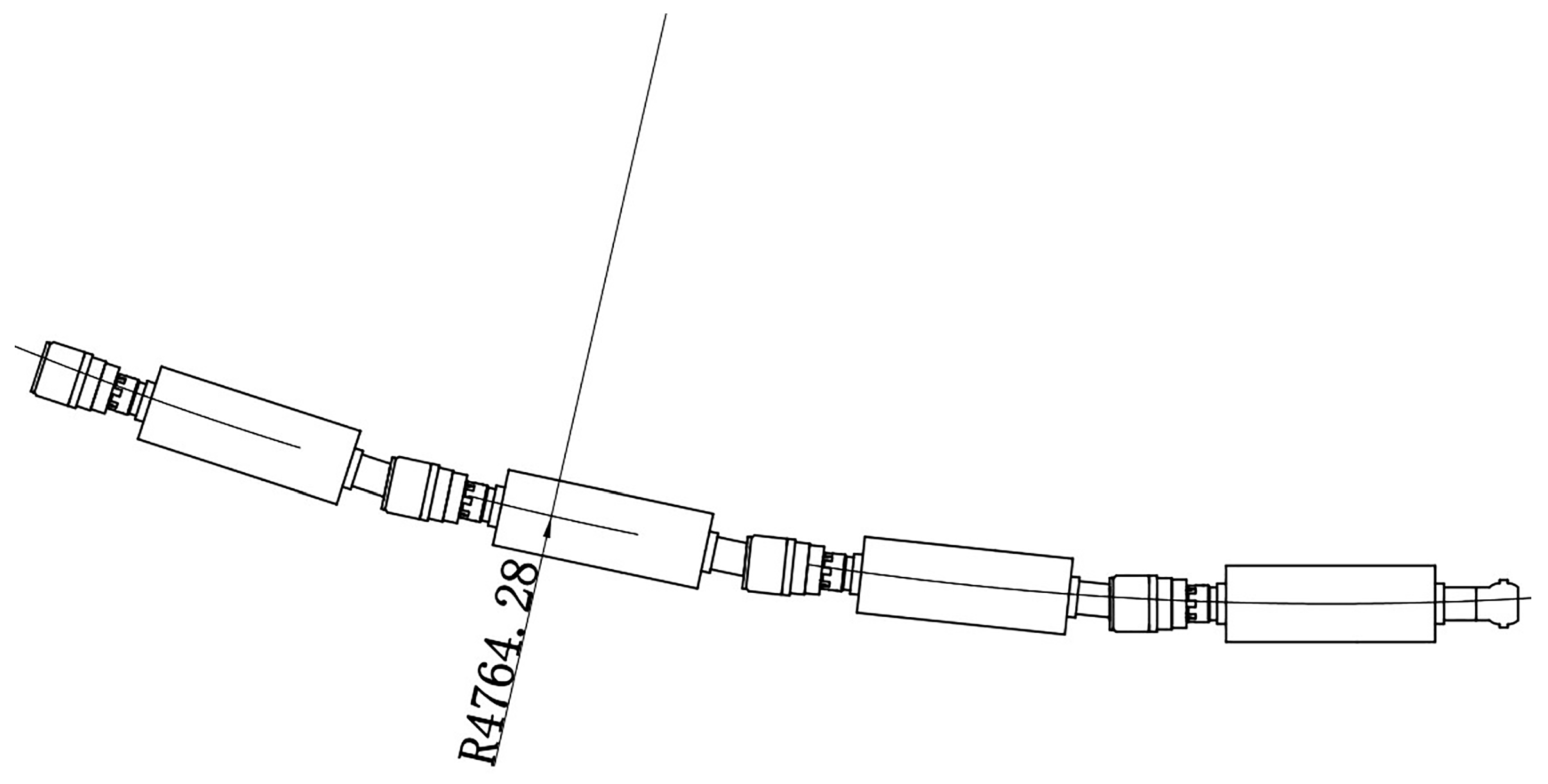
The first concern in designing the DFDR is to ensure its ability to be sent downhole through curved sections of the URHW. In other words, the maximum radius of the DFDR-inserted flexible string should fall within the radius range of the curved section of the URHW. Because a DFDR is longer than a normal flexible drill rod, assuming that a whole flexible string is composed of DFDRs, the maximum radius of the DFDR-added string is obtained. As shown in
Figure 1, this maximum radius is 4.76 m, which satisfies the requirement of the URHW curvature radius.
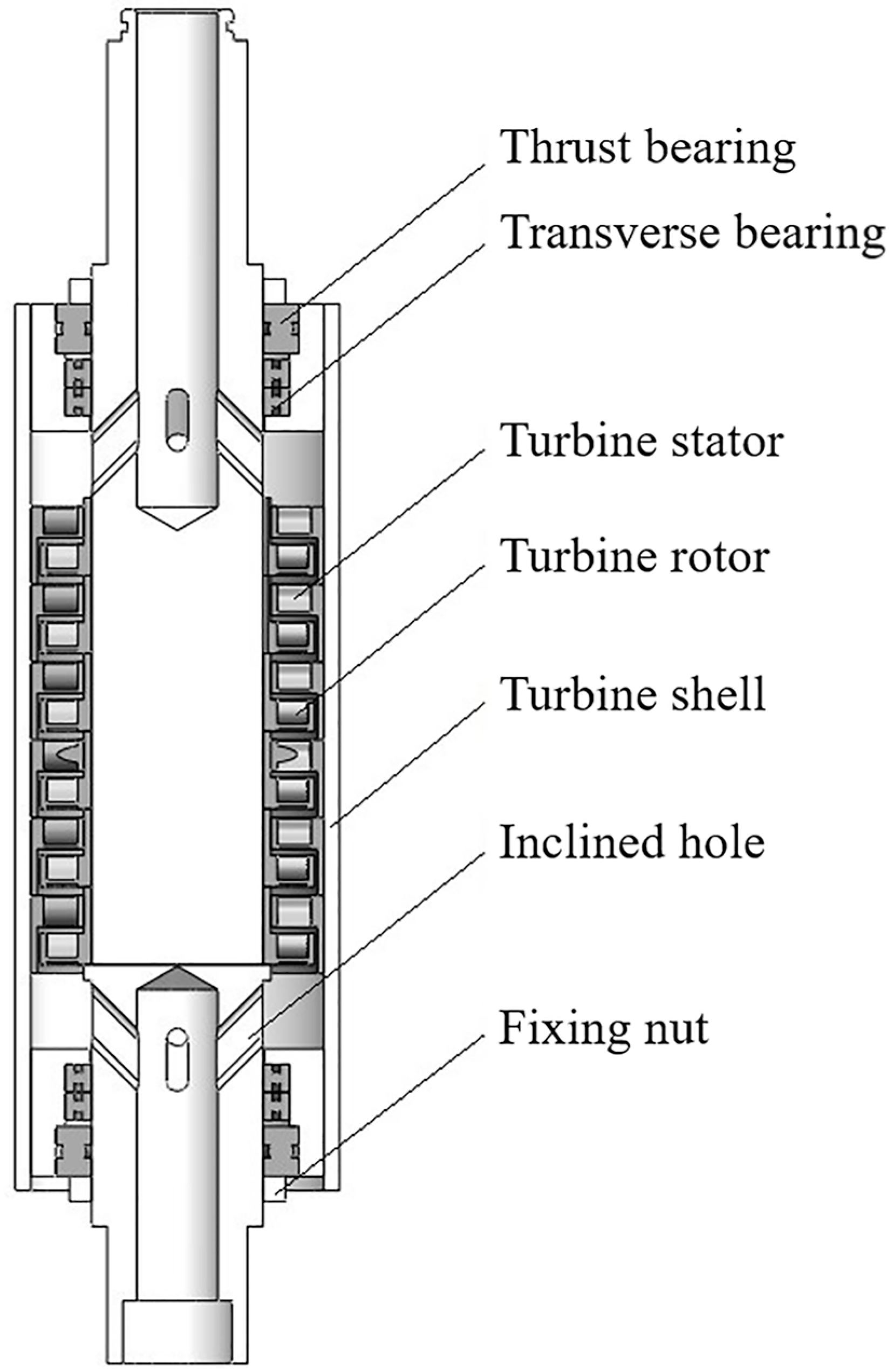
The working principle of the DFDR is illustrated by a cross-sectional view of its main functioning parts, as shown in
Figure 2. It is worth noting that the universal ball joint structures on both ends of the shaft are the same as those of normal flexible drill rods, and the anti-slip ridges that match the flexible anti-slip shell (shown in the later part of the paper) when drilling are not shown. The main part of the force transmission is the shaft, the middle part of which is solid, whereas the two ends are pipe structures. Each pipe has several inclined holes evenly distributed around its periphery. These inclined holes allow the drilling fluid to enter and exit the annular space between the shaft and turbine shell so that the fluid can run through the turbine stages. The cross-sectional area and number of upper (inlet) holes are the same as those of the lower (outlet) holes, but the two groups of holes have opposite axial inclining directions. As mentioned earlier, within the annular space, stators and rotors are fixed to the turbine shell and shaft, respectively; thus, when drilling fluid flows through one stage, torque is generated on the shaft. This process is repeated in multiple stages, by which a larger torque can be generated. The drilling fluid then flows through the lower inclined holes into the lower pipe and then into the next DFDR, where the above process is repeated. Both ends of the annular space have rotary seals that allow for low-friction rotation during sealing. Each rotary seal is composed of a thrust bearing, two transverse bearings, and rubber seal rings. Outside the rotary seals are the fixing nuts.
3. Simulation Model Establishment
FEM and CFD were used to conduct the mechanical and fluid dynamics simulations, respectively. The material of the DFDR shaft (and other component parts) and its mechanical properties are listed in
Table 1. The FEM analysis takes the von Mises yield criterion for the present 42CrMo material, which states that the material yields when its von Mises stress is equal to or greater than its yield limit under simple tension. This criterion can be expressed by
where
σv is the von Mises stress;
σ1,
σ2, and
σ3 are the three principal stresses; and
σy is the yield limit of the material.
Because the fluid domain of the current model involves multiple turbine stages, the flow is of a highly turbulent type. Therefore, in the CFD analysis, the standard k-ε turbulence model was adopted.
The mechanics and fluid dynamics of the drilling procedure satisfy the following equations:
where
M0 is the torque provided by ground power equipment;
Z is the number of DFDRs incorporated;
Mi is the outputting torque of a single DFDR;
and
are the average circumferential friction on the drill string and bit, respectively;
rs and
rw are the radii of the drill string and wellbore, respectively;
P0 is the total pressure provided by ground equipment; Δ
Pi is the pressure loss of a single DFDR; and Δ
Pw is the pressure loss along the wellbore.
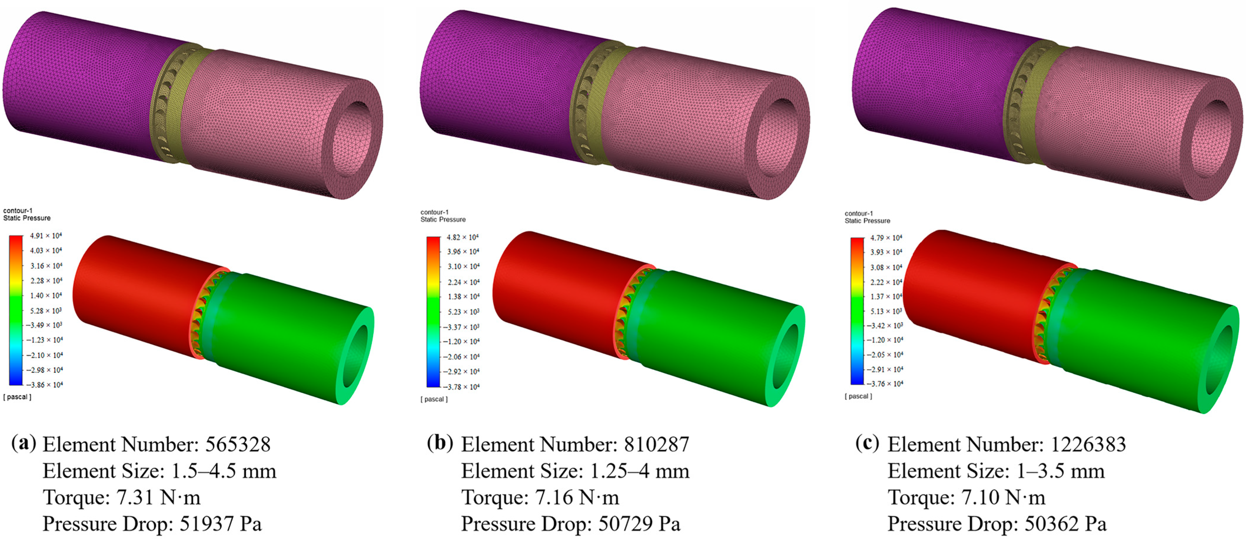
Grid independence tests were performed before the final number and size of the mesh were decided. An initial primitive (coarse-meshed) model typical of the formal simulation was first analyzed, with the results recorded. This was followed by a series of the same analyzing procedures on the re-meshed models with systematically refined elements until the recorded results from two consecutive analyses differed by within 1%. The number and size of the mesh of the last analysis were adopted in the formal simulation. A typical grid independence test for the more complicated CFD analysis is hereby presented in
Figure 3 to illustrate the grid independence test procedure undertaken by both the mechanical and fluid dynamics simulations. It can be seen from
Figure 3 that further refining of the grids will no longer produce significantly different results. Therefore, the grid number and size can be adopted for the formal simulation.
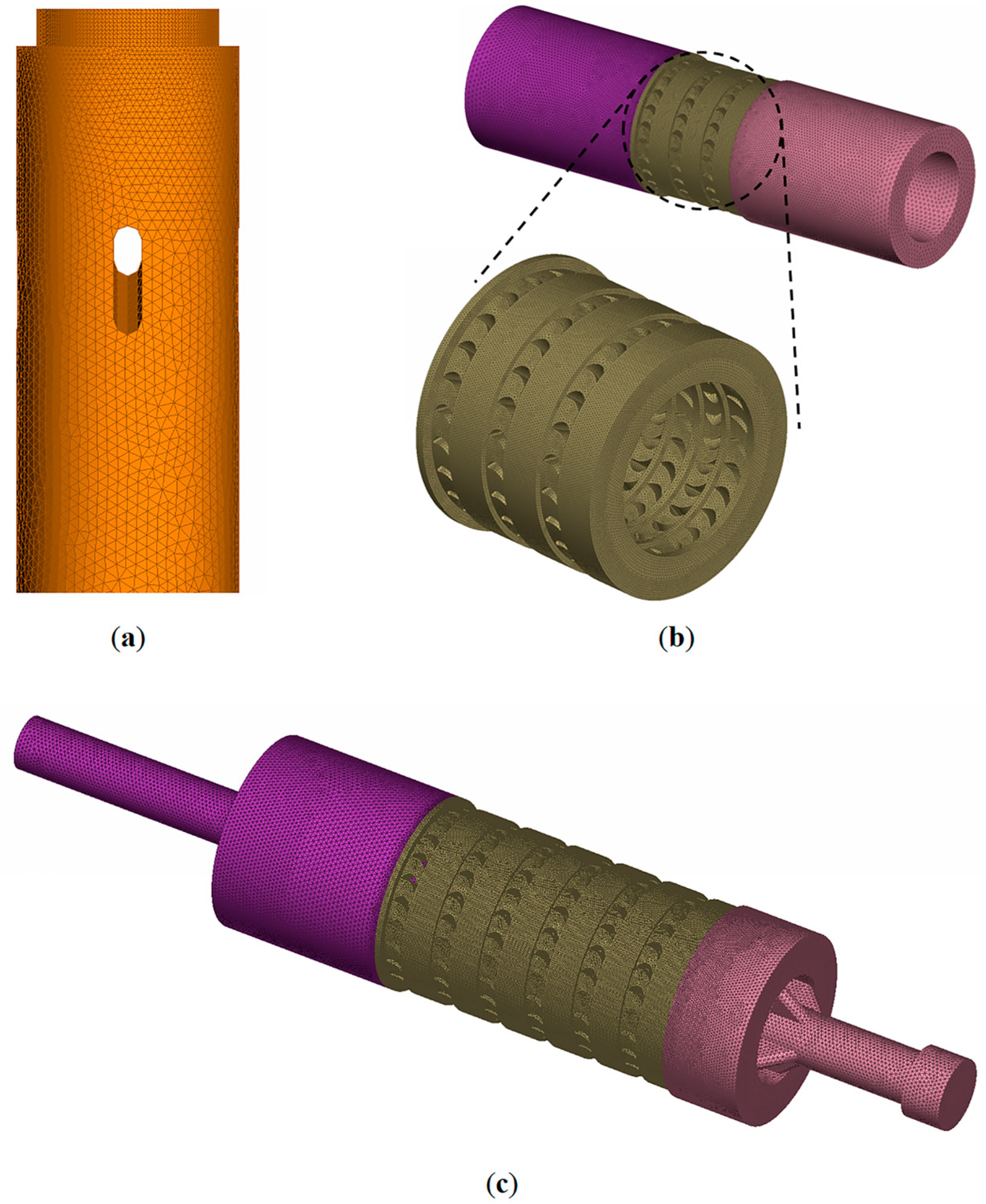
In the FEM analysis, the tetrahedral meshing method was used for the model meshing, with a mesh size of 1–3 mm. Local densification and transition of the mesh were adopted to increase precision and avoid problems such as a stress singularity. The meshing of the model is illustrated in
Figure 4a.
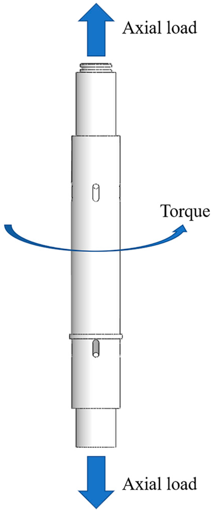
As the main load-bearing part of the DFDR, the shaft mainly bears axial loads and torques, as shown in
Figure 5. As mentioned earlier, potential tensile failure can occur on the shaft of the DFDR, causing serious downhole problems. Considering the current state of URHW drilling in the Chunliang District of the Shengli Oilfield, it is expected that 30 DFDRs should be incorporated within a flexible string to generate usable torque. However, in the simulation, to emulate more severe conditions, a safety factor of 1.5 was adopted, so 45 DFDRs should be considered. When a DFDR string is sent downhole or lifted out of the hole, the string is suspended, and the shaft of the uppermost DFDR bears an axial load equal to the weight of the entire flexible string. Therefore, in the tensile simulation, one end of the shaft model was set to “fixed”, and a 6.70 kN axial outward load (corresponding to the weight of 45 DFDRs) was applied to the other end as the boundary condition.
In the CFD analysis, the drilling fluid properties were in accordance with the real URHW drilling conditions, the details of which are given in
Table 2. The boundary conditions were flow rate inlet (9 L/s) and pressure outlet (0 MPa; hence, the pressure values obtained in this simulation are relative values; real values equal to real outlet pressure plus relative values). The near-wall treatment of the fluid domain followed the standard wall function and no-slip condition. CFD analysis was first performed at the level of the turbine stages. The fluid domains of 1–6 turbine stages were extracted, meshed (with a mesh size of 1–3.5 mm), and resolved. Then followed the analysis on the whole-set DFDR level, where fluid domains of 1–3 connected DFDRs went through the same procedure as was performed for the turbine stages. The meshing of the fluid domains is illustrated in
Figure 4b,c. The meshing also adopted the tetrahedral meshing method with local densification and transition to ensure the precision of the simulation. Furthermore, as shown in
Figure 4b, the inlet and outlet of the fluid domains were extended to reduce the potential error introduced by the sudden change in the cross section of the fluid domain.
4. Results and Discussion
4.1. Mechanical Simulation
The mechanical simulation results are shown in
Figure 6. It can be seen from the equivalent stress (von Mises stress) contour that higher stresses were distributed mainly on the pipe structures of the shaft, especially at the ends of the pipes. In contrast, the solid middle part of the shaft had low stress. Such a distribution of stress is in accordance with fieldwork failure cases where most fractures occur at the joints of neighboring flexible drill rods, leading to the breaking-off of the flexible drill strings. According to the simulation results, under a weight load of 45 DFDRs, no area within the shaft showed a stress that was significantly close to the yield strength. The maximum stress reached was 91.74 MPa which is far less than the material’s yield strength of 930 MPa. This indicates that the drilling operation under the 30-DFDR scenario has a very small chance of encountering a tensile failure.
4.2. CFD on Turbine Stages
The torque generated by one turbine stage is determined by several factors concerning the fluid state, turbine stage configuration, and rotational speed of the rotors [
21], and can be calculated as [
22]
where
ρ is the fluid density,
Qi is the flow rate,
b is the axial height of the stage,
φ is the cross-section diminishing rate,
α1k is the inflow angle of the stator blade,
β2k is the outflow angle of the rotor blade,
D is the nominal diameter of the cross section of the flow path, and
n is the rotary speed of the rotor. In the above parameters,
b and
D are calculated respectively as [
22]
where
D1 and
D2 are the outer and inner diameters of the cross section of the flow path, respectively.
Based on the design of the model stage,
D1 = 86 mm,
D2 = 64 mm,
φ = 0.7, and
α1k =
β2k = 30°. As listed in
Table 2, the drilling fluid density set in CFD is
ρ = 1.19 × 10
3 kg/m
3, and the flow rate is
Qi = 9 L/s. The DFDR provides torque when the flexible drill string is stopped by wellbore friction; therefore, it functions at zero rotary speed. Thus, the calculated result of torque generated by a single DFDR turbine stage was 6.90 N·m.
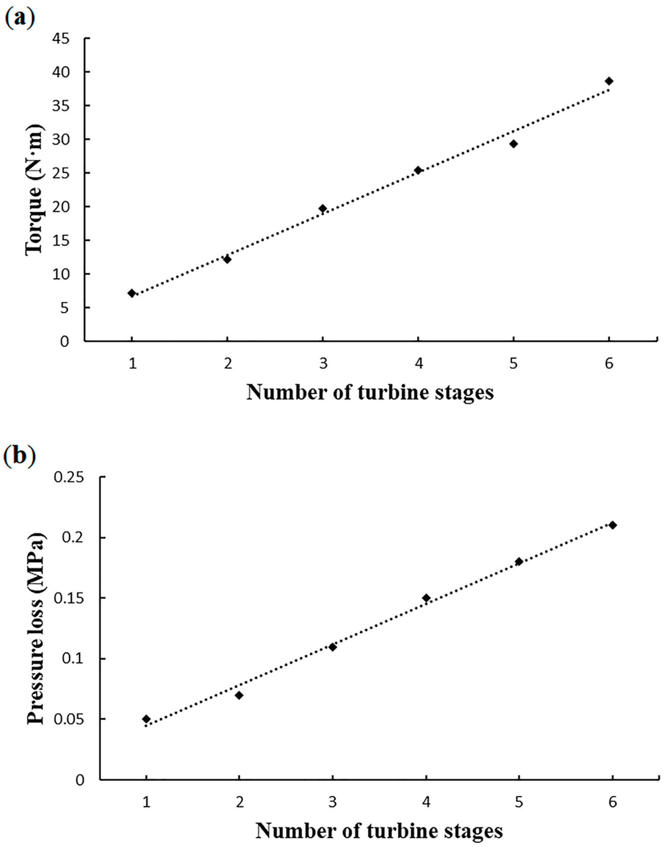
Figure 7a shows the torque results of the turbine stages obtained using the CFD analysis. It can be seen from these results that a single turbine stage generates 7.10 N·m of torque under the URHW working condition, which is essentially in agreement with the calculation result. It is also known that the turbine group of the current six-stage DFDR can theoretically produce a total torque of 38.62 N·m. It can be clearly observed that the total torque increases linearly with the number of turbine stages. This pattern can provide a reference for the prediction of the torque value of a group of turbine stages within the DFDR in the follow-up design optimization.
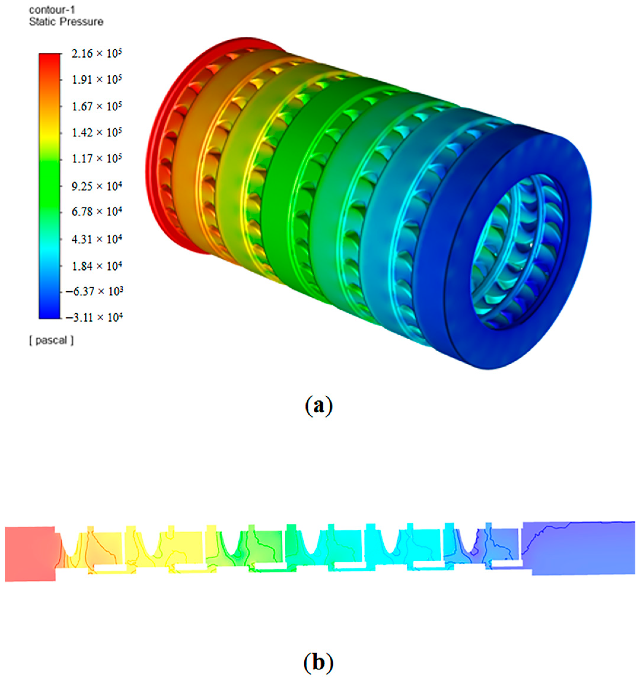
Figure 8 shows the pressure distribution within the six turbine stages. It can be seen from
Figure 8a that the pressure loss within a stage mainly occurs on the two sides of the turbine blades; and, as shown in
Figure 8b, the pressure of the drilling fluid gradually decreases as the axial distance increases along the turbine group. This is because the shape of the blades is specially designed and placed for directing flow and producing impacts between the fluid and blades, through which process the pressure energy is converted into other forms of mechanical energy. The pressure loss values of 1–6 turbine stages are shown in
Figure 7b, which clearly demonstrates that the total pressure loss also follows a linearly increasing trend with respect to the number of turbine stages.
4.3. CFD on DFDR Whole Sets
CFD analysis of the connected DFDR whole sets indicated a linear increasing pattern of output torque and pressure loss similar to that of the turbine stages. The torque and the pressure loss of a single DFDR are 36.35 N·m and 0.71 MPa, respectively. This information is helpful in predicting the total torque (Mt) and pressure loss (ΔPt) of a DFDR string as functions of the number of DFDRs incorporated, providing a reference for fieldwork parameter formulation.
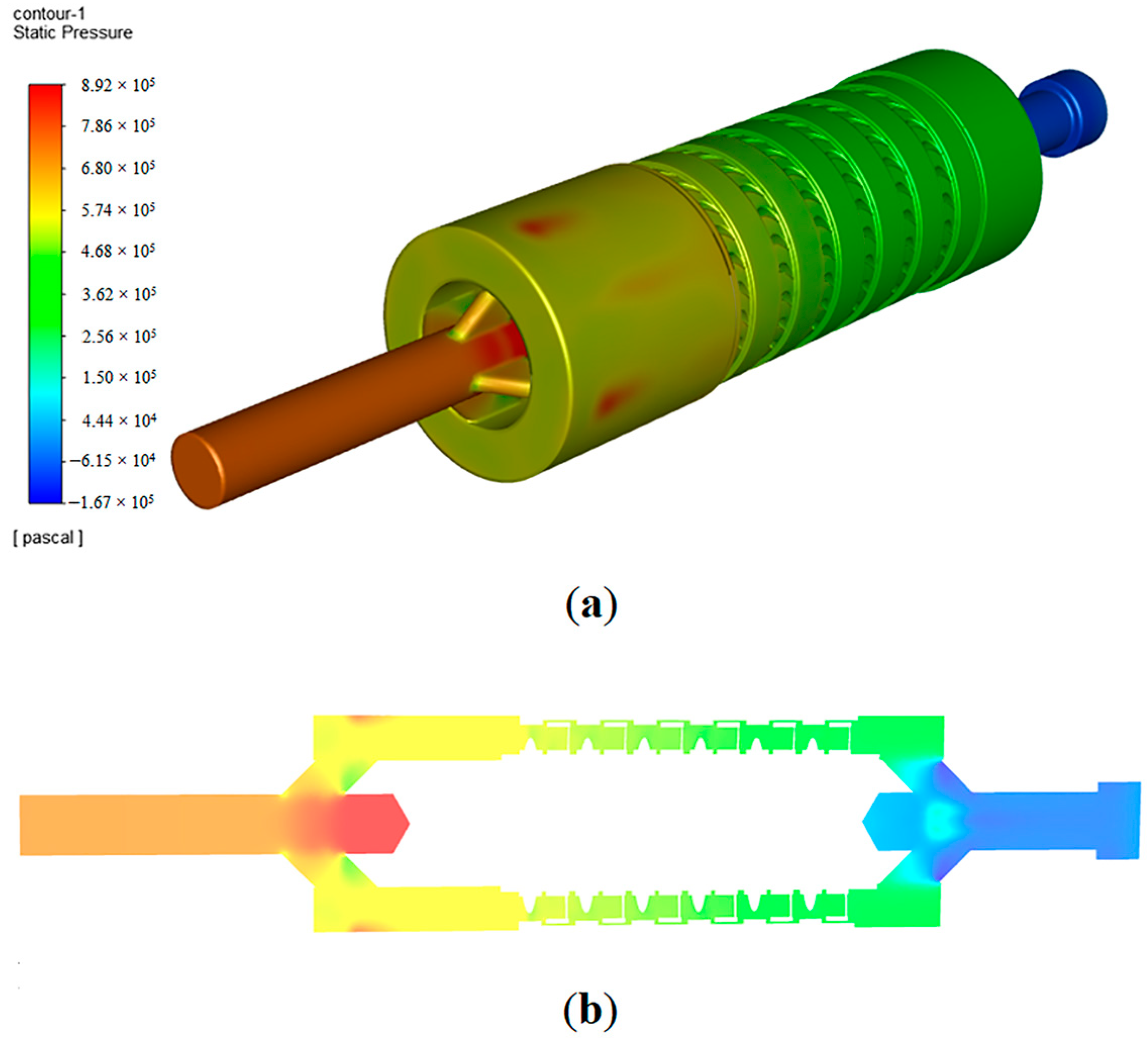
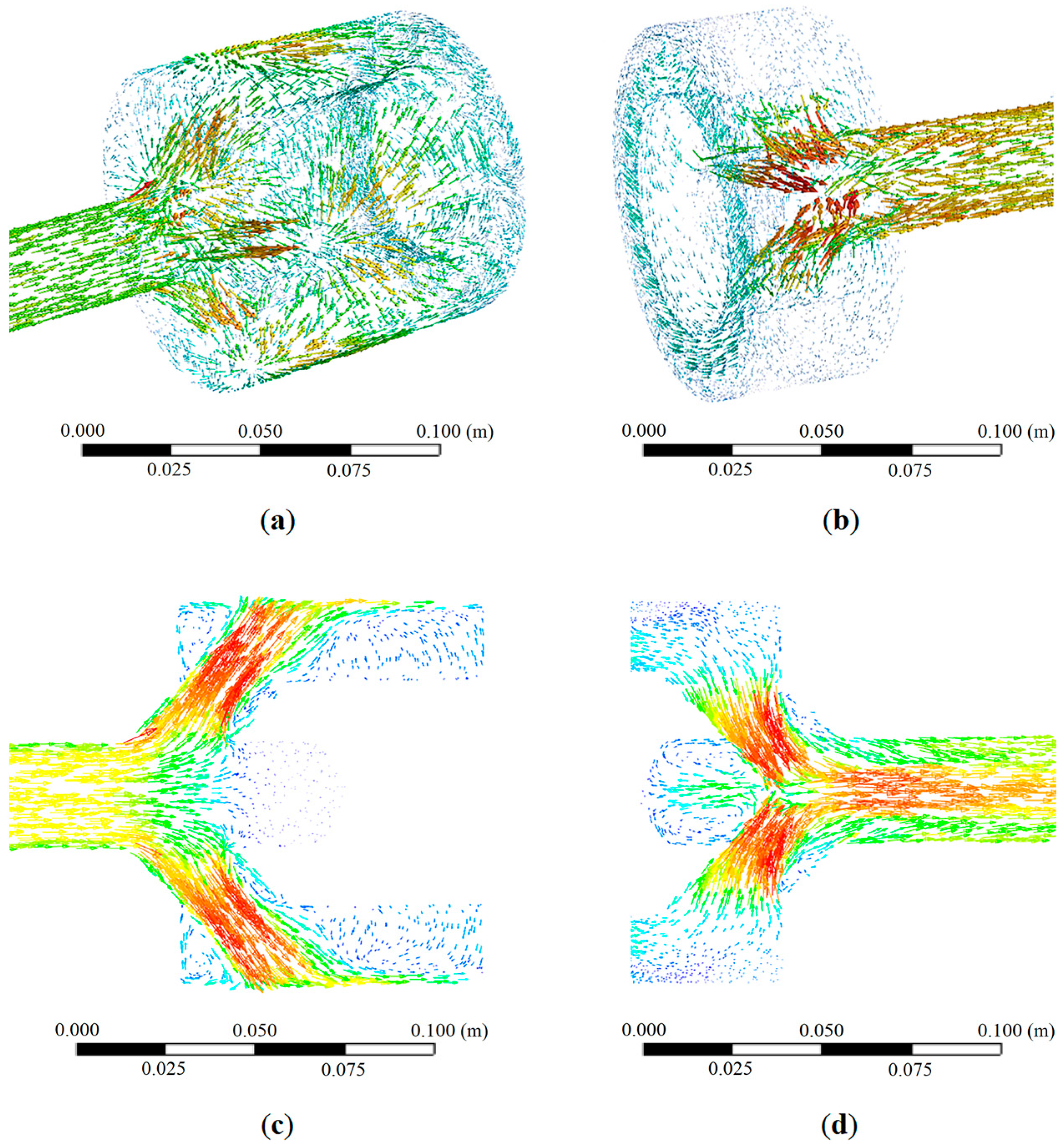
Figure 9 shows the pressure distribution within the fluid domain of a single DFDR set. It can be seen that, except for the pressure loss in the turbine stages, major pressure loss occurs at the inclined hole areas. As shown in
Figure 10a,b, this is mainly because the total cross-sectional area of either the upper or lower group of inclined holes is slightly less than that of the pipe’s cross-sectional area for fluid flow, which is responsible for a rapid velocity increase in the fluid flow. Moreover, as shown in
Figure 10c,d, the flowing direction experiences a sharp diversion owing to the relatively high angle of inclination of the holes, leading to an abrupt change in fluid momentum. A rapid change in flowing direction also causes a significant pressure drop in the fluid flow. Furthermore, the concave structures on both sides of the shaft are responsible for a portion of the pressure loss, as they introduce turbulence and eddies along the flowing path of the drilling fluid. Therefore, to reduce this aspect of pressure loss, follow-up optimization towards the DFDR model should include an increase in the cross-sectional area of the inclined holes or the number of holes on the premise of not undermining the shaft’s mechanical strength, a reduction in the angle of inclination of the holes, and the cancellation of the concave structures on both sides of the shaft.
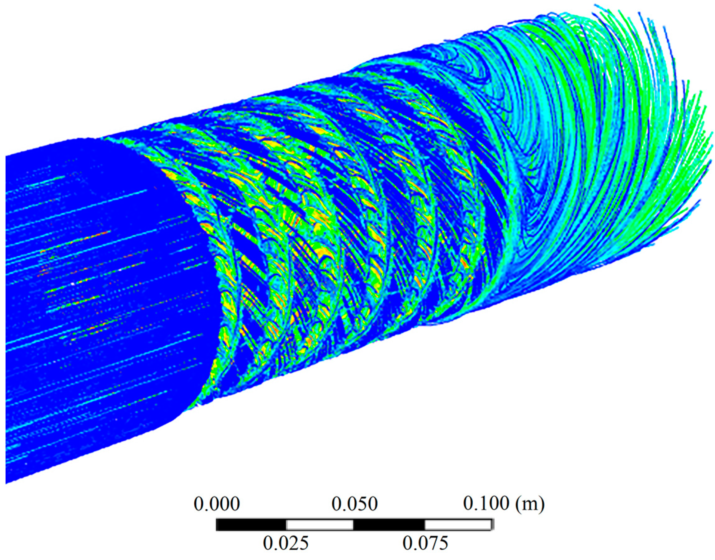
From CFD analysis results, it is known that three major pressure loss areas exist within each DFDR: the inlet area (0.18 MPa), the turbine stages area (0.22 MPa), and the outlet area (0.31 MPa). It is interesting to find that although the upper and lower groups of inclined holes are of the same cross-sectional area, number of holes, and angle of inclination, the pressure losses of the two areas are obviously different, with the pressure loss of the inlet area being significantly less than that of the outlet area. From the streamline trajectory of the six turbine stages shown in
Figure 11, we can see that the streamlines behind the turbine stages are highly chaotic, which is indicative of turbulence and eddies that exert resistance to the fluid flow. This phenomenon causes a greater pressure drop in the outlet area.
5. Field Trials
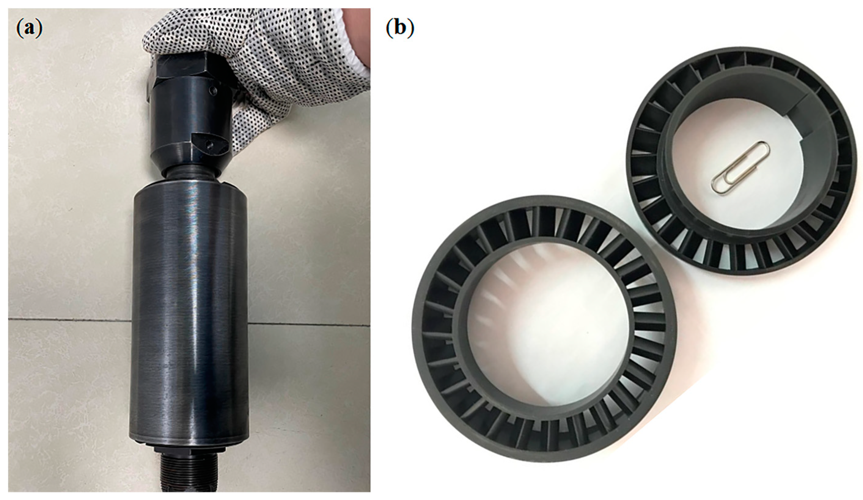
Based on the simulation results, modifications were made to the design of the inclined holes. The axial length of the cross section of each hole was elongated to increase the cross-sectional area; the angle of inclination of each hole was reduced, and one more hole was added within each group. The concave structures on both sides of the shaft were removed. As discussed previously, these modifications aim to reduce the pressure loss at the inclined hole areas and preserve the pressure energy for the turbines. The simulation results show that these modifications reduce the pressure loss of a single DFDR by 18.31% (0.58 MPa). As described in the previous sections, the increase in the length of the shaft and the corresponding increase in the number of turbine stages can proportionally increase the torque output of a single DFDR. Meanwhile, the current six-stage DFDRs axial length can still be significantly increased to incorporate more turbine stages while still satisfying the general requirement for the curvature radius of the URHW. However, as the target formations in the field trial area are very close to those of old wellbores, and thus the current flexible drilling assembly corresponds to a 3–5 m curvature radius, it was decided that the current shaft length should not be modified to conform to the situation at the field trial spots. The model machines were then produced (as shown in
Figure 12).
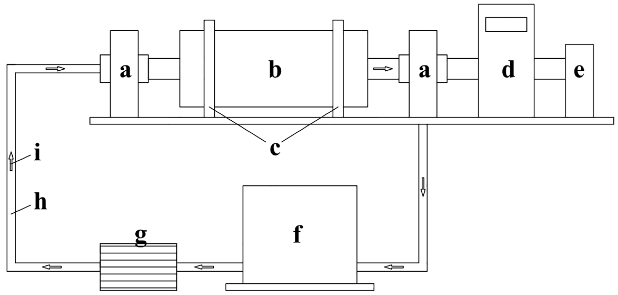
Before formal field trials, pilot tests on individual DFDRs were conducted on site via a ground circulation system (as shown in
Figure 13). The results showed that a single DFDR can produce 33.79 N·m of torque and 0.61 MPa of pressure loss on average, which was essentially in accordance with and verified the CFD results.
Field trials of DFDR-based URHW drilling have been conducted in Chunliang District, Shengli Oilfield. The target formations in this area are extremely difficult to drill. Existing data show that the URHWs (by 3–5 m curvature radius standard) in this area have an average horizontal length of 19.17 m. In the later stage of drilling, owing to the influence of extremely high wellbore friction, the rotary speed gradually decreases to zero, and all the torque provided by the ground power equipment was offset by wellbore friction, making the drill bits unable to receive the torque needed to break the rocks. The trials were carried out in three old wells, each performing two DFDR-based URHW drillings at different depths. As planned, 30 DFDRs were incorporated into the flexible drill string. A schematic of the downhole pipe structure is shown in
Figure 14.
DFDR-based URHW drilling is an innovative drilling technique and includes the following procedures: (1) clear the main hole to ensure that the old wellbore is unblocked; (2) conduct pressure tests to avoid wellbore decompression; (3) send down the whipstock to the appointed depth, calibrate depth and direction, and anchor the whipstock by ball throwing and adding pressure; (4) send down the windowing assembly, open and polish a window, and then pull out the windowing assembly; (5) send down the flexible drilling assembly for curved section drilling, and drill out a curved section with a 5 m (in other cases 3–30 m) radius; (6) send down a normal flexible drilling assembly for horizontal section drilling, and drill to the limit, forming an initial horizontal hole; (7) send down the flexible anti-slip shell, then send down the DFDR-based flexible drilling assembly to the end of the initial horizontal hole, drill to the limit, and pull out the assembly.
Field trial results are given in
Table 3 and shown in
Figure 15. The results show that adopting a DFDR-based drill string assembly and the corresponding drilling technique produced beneficial effects. From
Figure 15, it can be clearly seen that the application of the DFDR has extended the horizontal length of each URHW; the Extension Rate is not necessarily dependent on the Depth or the Initial Horizontal Length. It can be seen from
Table 3 that the new machine has extended the URHWs horizontal section length in this difficult area by 8.02–17.46%, with an average extension rate of 13.38%. During the field trials, it was discovered that the functioning mechanism of the DFDR assembly is not just providing extra torque for the bit. On overcoming the maximum static friction of the wellbore, the assembly tends to keep rotating under a relatively small dynamic friction. In other words, a sudden drop occurs in the friction between the assembly and the wellbore. At this moment, an intense increase in the torque transmitted from the ground power equipment is observed, and this increased torque maintains the rotation of the assembly for some time. It has also been observed in the drilling trials that the DFDR-based technique can help in the transmission of weight to the bit. This may be because although the DFDR string overcomes the wellbore’s circumferential friction, the process also has a positive effect on overcoming axial wellbore friction.
6. Conclusions
The primary obstacle to extending the horizontal section in the URHW drilling engineering is the inefficiency in torque transmission caused by wellbore friction. To tackle this problem, we proposed the new downhole machine design of DFDR which aims to utilize the energy of the drilling fluid to provide extra torque near the drill bit. The interior structure and working principle have been illustrated in detail, followed by the FEM analysis of the mechanical strength and the CFD analysis of the fluid domains. The feasibility of the design and the safety of use concerning the mechanical strength of the critical load-bearing part were verified. The behavior of the two important parameters on two levels has been revealed: at the turbine level, torque and pressure loss both increase in direct proportion to the number of turbine stages; at the level of the DFDR whole sets, torque and pressure loss also increase linearly with the number of DFDRs connected. These results provide directive opinions regarding machine design modifications and fieldwork parameter decisions. Based on the CFD analysis results, the following modifications were made to optimize the machine design: the axial length of the cross-sectional area of the inclined holes was increased, the angle of inclination was reduced, one more hole was added within each group, and the concave structures on both sides of the shaft were removed. These modifications lowered the pressure loss in the DFDR. An increase in the shaft length and the corresponding number of turbine stages is still an advisable optimization option to boost torque output under situations that allow a greater curvature radius, as the length of the current shaft conforms with a very strict curvature radius standard. Field trials verified the CFD results and showed that by adopting the new DFDR-based drilling engineering, the length of the horizontal section of the URHW increased by 13.38% on average, making this new machine promising for increasing the oil recovery factor and obtaining greater economic benefits.
Author Contributions
Conceptualization, C.L. and R.D.; methodology, Z.W.; software, C.L. and Z.C.; validation, C.L. and Q.T.; formal analysis, C.L. and K.W.; investigation, C.L.; writing—original draft preparation, C.L.; writing—review and editing, C.L. and K.W.; visualization, C.L.; supervision, Z.W. All authors have read and agreed to the published version of the manuscript.
Funding
This research received no external funding.
Data Availability Statement
The data presented in this study are available on request from the corresponding author.
Conflicts of Interest
The authors declare no conflict of interest.
References
- Bruni, M.; Biassotti, H.; Salomone, G. Radial drilling in Argentina. In Proceedings of the 2007 SPE Latin American and Caribbean Petroleum Engineering Conference, Buenos Aires, Argentina, 15–18 April 2007. [Google Scholar]
- Dickinson, W.; Sykstra, H.; Nees, J.M.; Dickinson, E. The Ultrashort Radius Radial System applied to thermal recovery of heavy oil. In Proceedings of the Western Regional Meeting, Bakersfield, CA, USA, 30 March–1 April 1992. [Google Scholar]
- Stiles, E.K.; DeRoeun, M.W.; Terry, I.J.; Cornell, S.P.; DuPuy, S.J. Coiled tubing ultrashort-radius horizontal drilling in a gas storage reservoir: A case study. In Proceedings of the 1999 SPE Eastern Regional Meeting, Charleston, WV, USA, 21–22 October 1999. [Google Scholar]
- Abdel-Ghany, M.A.; Siso, S.; Hassan, A.M.; Pierpaolo, P.; Roberto, C. New technology application, radial drilling petrobel, first well in Egypt. In Proceedings of the 10th Offshore Mediterranean Conference and Exhibition, Ravenna, Italy, 23–25 March 2011. [Google Scholar]
- Liu, C.; Song, X.; Xu, X.; Zong, H.; Guo, Y. Adaptability analysis of ultra-short radius sidetracking horizontal well technology. In Proceedings of the International Field Exploration and Development Conference, Singapore, 9 October 2022. [Google Scholar]
- Sun, Q.; Zhang, S.; Li, T.; Ming, E.; Huang, S.; Han, W.; Chen, Q. Research and application on the technology of ultra-short radius sidetracking using flexible drilling pipe. In Proceedings of the International Field Exploration and Development Conference 2017; Springer: Singapore, 2019; pp. 1292–1303. [Google Scholar]
- Ma, D.; Li, G.; Huang, Z.; Niu, J.; Hou, C.; Liu, M.; Li, J. A model of calculating the circulating pressure loss in coiled tubing ultra-short radius radial drilling. Pet. Explor. Dev. 2012, 39, 528–533. [Google Scholar] [CrossRef]
- Marbun, B.T.H.; Sinaga, S.Z.; Arliyando, L.; Putra, S.K. Review of Ultrashort-Radius Radial System (URRS). In Proceedings of the International Petroleum Technology Conference, Bangkok, Thailand, 2–9 February 2012. [Google Scholar]
- Cinelli, S.D.; Kamel, A.H. Novel technique to drill horizontal laterals revitalizes aging field. In Proceedings of the SPE/IADC Drilling Conference and Exhibition, Amsterdam, The Netherlands, 5–7 March 2013. [Google Scholar]
- Perves, T.; Al-Hiddabi, S.A.; Al-Yahmadi, A.; Seibi, A.C. Dynamic analysis and vibration of beam inside annulus for ultra short-radius water jet drilling. J. Eng. Res. 2011, 9, 55–63. [Google Scholar] [CrossRef] [Green Version]
- Liu, H.; Huang, S.; Sun, Q.; Ming, E.; Li, T.; Han, W.; Chen, Q.; Li, Y.; Pei, X.; Zhang, S. Application of ultrashort radius lateral drilling technique in top thick reservoir exploitation after long term water flooding. In Proceedings of the Abu Dhabi International Petroleum Exhibition & Conference, Abu Dhabi, United Arab Emirates, 13–16 November 2016. [Google Scholar]
- Wang, Y. Application of ultra-short radius horizontal well drilling technology in plugging removal in injectors. Pet. Drill. Tech. 2013, 41, 89–92. [Google Scholar]
- Ming, E.; Li, Y.; Li, T.; Huang, S. Improvement and prospect of ultrashort radius lateral drilling technique. In Proceedings of the SPE/IATMI Asia Pacific Oil & Gas Conference and Exhibition, Jakarta, Indonesia, 17–19 October 2017. [Google Scholar]
- Luo, M.; Xu, T.; Jia, L.; Lv, F. Nonlinear mechanics analysis of flexible drill rod in ultra short radius horizontal well. Mach. Des. Manuf. Eng. 2016, 45, 21–24. [Google Scholar]
- Liu, H.; Zhang, S.; Sun, Q.; Li, T.; Ming, E.; Huang, S.; Han, W.; Chen, Q.; Li, Y.; Pei, X. Research and application of ultra-short radius flexible sealed coring technology in redevelopment of matured fields. In Proceedings of the Abu Dhabi International Petroleum Exhibition & Conference, Abu Dhabi, United Arab Emirates, 13–16 November 2017. [Google Scholar]
- Li, Y.; Wang, C.; Shi, L.; Guo, W. Application and development of drilling and completion of the ultrashort-radius radial well by high pressure jet flow technique. In Proceedings of the SPE International Oil and Gas Conference and Exhibition in China, Beijing, China, 7–10 November 2000. [Google Scholar]
- Al-Hady, A.S.; LaPrad, D.; Sadi, A.A. Ultra short radius drilling trials in PDO. In Proceedings of the SPE 13th Middle East Oil Show & Conference, Bahrain, 5–8 April 2003. [Google Scholar]
- Yang, J.; Zheng, R. Drilling and completion technology for a two-branch multi-lateral ultra-short radius horizontal well: Maojia 65-82, Daqing Oilfield. Pet. Drill. Tech. 2016, 44, 63–66. [Google Scholar]
- Gong, H.; Zheng, R.; Fan, C.; Xu, Y.; Geng, X.; Zhang, Z. Ultra-short radius horizontal well drilling technology in Daqing Oilfield. Pet. Drill. Tech. 2011, 39, 19–22. [Google Scholar]
- Liu, Q.; Tong, K.; Zhu, G.; Tan, Y.; Zhang, J.; Xu, X.; Li, X.; Song, S. Investigation of fracture causes of the titanium alloy drill pipe in ultra-short radius horizontal well drilling. Eng. Fail. Anal. 2022, 140, 106516. [Google Scholar] [CrossRef]
- Zhang, D.; Wang, Y.; Sha, J.; He, Y. Performance prediction of a turbodrill based on the properties of the drilling fluid. Machines 2021, 9, 76. [Google Scholar] [CrossRef]
- Tan, C. The ROP Technical Research on Turbo-Drill Composite Drilling in Deep & Ultra-Deep Well. Ph.D. Thesis, China University of Geosciences (Beijing), Beijing, China, 2012. [Google Scholar]
Figure 1.
Schematic showing the maximum radius of DFDR-inserted flexible drill string (when the whole string is composed of DFDR).
Figure 1.
Schematic showing the maximum radius of DFDR-inserted flexible drill string (when the whole string is composed of DFDR).
Figure 2.
Cross-sectional view of DFDRs main functioning parts.
Figure 2.
Cross-sectional view of DFDRs main functioning parts.
Figure 3.
A typical grid independence test procedure: (a) the third-to-last result; (b) the second-to-last result; (c) the last result.
Figure 3.
A typical grid independence test procedure: (a) the third-to-last result; (b) the second-to-last result; (c) the last result.
Figure 4.
Meshing of the models: (a) meshing of the shaft model; (b) meshing of the fluid domain of the three-stage turbine; (c) meshing of the fluid domain of the whole-set DFDR model.
Figure 4.
Meshing of the models: (a) meshing of the shaft model; (b) meshing of the fluid domain of the three-stage turbine; (c) meshing of the fluid domain of the whole-set DFDR model.
Figure 5.
Main load and torque on the DFDR shaft.
Figure 5.
Main load and torque on the DFDR shaft.
Figure 6.
FEM simulation result on the tensile strength of the DFDRs shaft.
Figure 6.
FEM simulation result on the tensile strength of the DFDRs shaft.
Figure 7.
Torque and pressure loss results of 1–6 turbine stages. (a) torque results; (b) pressure loss results.
Figure 7.
Torque and pressure loss results of 1–6 turbine stages. (a) torque results; (b) pressure loss results.
Figure 8.
Pressure contour of six turbine stages. (a) overview of the pressure distribution within six turbine stages; (b) cross-sectional view of the pressure distribution within six turbine stages.
Figure 8.
Pressure contour of six turbine stages. (a) overview of the pressure distribution within six turbine stages; (b) cross-sectional view of the pressure distribution within six turbine stages.
Figure 9.
Pressure contour of a DFDR whole set: (a) overview of the pressure distribution within a DFDR whole set; (b) cross-sectional view of the pressure distribution within a DFDR whole set.
Figure 9.
Pressure contour of a DFDR whole set: (a) overview of the pressure distribution within a DFDR whole set; (b) cross-sectional view of the pressure distribution within a DFDR whole set.
Figure 10.
Velocity vector results at the inclined hole areas: (a) overview of the velocity vector result at the upper (inlet) inclined hole area; (b) overview of the velocity vector result at the lower (outlet) inclined hole area; (c) cross-sectional view of the velocity vector result at the upper (inlet) inclined hole area; (d) cross-sectional view of the velocity vector result at the lower (outlet) inclined hole area.
Figure 11.
Streamline trajectory of six turbine stages.
Figure 11.
Streamline trajectory of six turbine stages.
Figure 12.
DFDR model machine parts manufacture and assembly. (a) A DFDR model machine in the assembling process; (b) the manufactured turbine stage.
Figure 12.
DFDR model machine parts manufacture and assembly. (a) A DFDR model machine in the assembling process; (b) the manufactured turbine stage.
Figure 13.
Schematic of the circulation system for pilot testing (a) shaft end casings; (b) DFDR model machine; (c) fixing clamps; (d) torque sensor; (e) loading device; (f) water tank; (g) pump; (h) water pipes; (i) flowing direction.
Figure 13.
Schematic of the circulation system for pilot testing (a) shaft end casings; (b) DFDR model machine; (c) fixing clamps; (d) torque sensor; (e) loading device; (f) water tank; (g) pump; (h) water pipes; (i) flowing direction.
Figure 14.
Schematic of downhole pipe structure of DFDR-based URHW drilling.
Figure 14.
Schematic of downhole pipe structure of DFDR-based URHW drilling.
Figure 15.
Results for DFDR-based field trials. (a) Extension Rate vs. Initial Horizontal Length; (b) Extension Rate vs. Depth; (c) extended length of each URHW.
Figure 15.
Results for DFDR-based field trials. (a) Extension Rate vs. Initial Horizontal Length; (b) Extension Rate vs. Depth; (c) extended length of each URHW.
Table 1.
Material mechanical properties of DFDR.
Table 1.
Material mechanical properties of DFDR.
| Material | Young’s Modulus (GPa) | Poisson’s Ratio | Yield Strength, σs (MPa) | Tensile Strength, σb (MPa) |
|---|
| 42CrMo | 212 | 0.28 | 930 | 1080 |
Table 2.
Properties of the drilling fluid set in CFD analysis.
Table 2.
Properties of the drilling fluid set in CFD analysis.
| Description | Density (kg/m3) | Viscosity (mPa·s) | Flow rate (L/s) |
|---|
| URHW drilling fluid | 1.19 × 10³ | 1.50 | 9.00 |
Table 3.
Results of DFDR-based URHW drilling field trials.
Table 3.
Results of DFDR-based URHW drilling field trials.
| Well Number | Depth (m) | Initial Horizontal Length (m) | Total Horizontal Length (m) | Extension Rate (%) |
|---|
| 1 | 870 | 19.37 | 21.75 | 12.29 |
| 2 | 960 | 16.84 | 18.64 | 10.69 |
| 3 | 830 | 12.10 | 13.92 | 15.04 |
| 4 | 930 | 15.35 | 18.03 | 17.46 |
| 5 | 810 | 14.84 | 16.03 | 8.02 |
| 6 | 1010 | 12.69 | 14.82 | 16.87 |
| Disclaimer/Publisher’s Note: The statements, opinions and data contained in all publications are solely those of the individual author(s) and contributor(s) and not of MDPI and/or the editor(s). MDPI and/or the editor(s) disclaim responsibility for any injury to people or property resulting from any ideas, methods, instructions or products referred to in the content. |
© 2023 by the authors. Licensee MDPI, Basel, Switzerland. This article is an open access article distributed under the terms and conditions of the Creative Commons Attribution (CC BY) license (https://creativecommons.org/licenses/by/4.0/).


