Dynamic Modeling and Analysis of Epoxy Gear Considering Material Viscoelasticity


Abstract
:1. Introduction
2. Modeling Approach
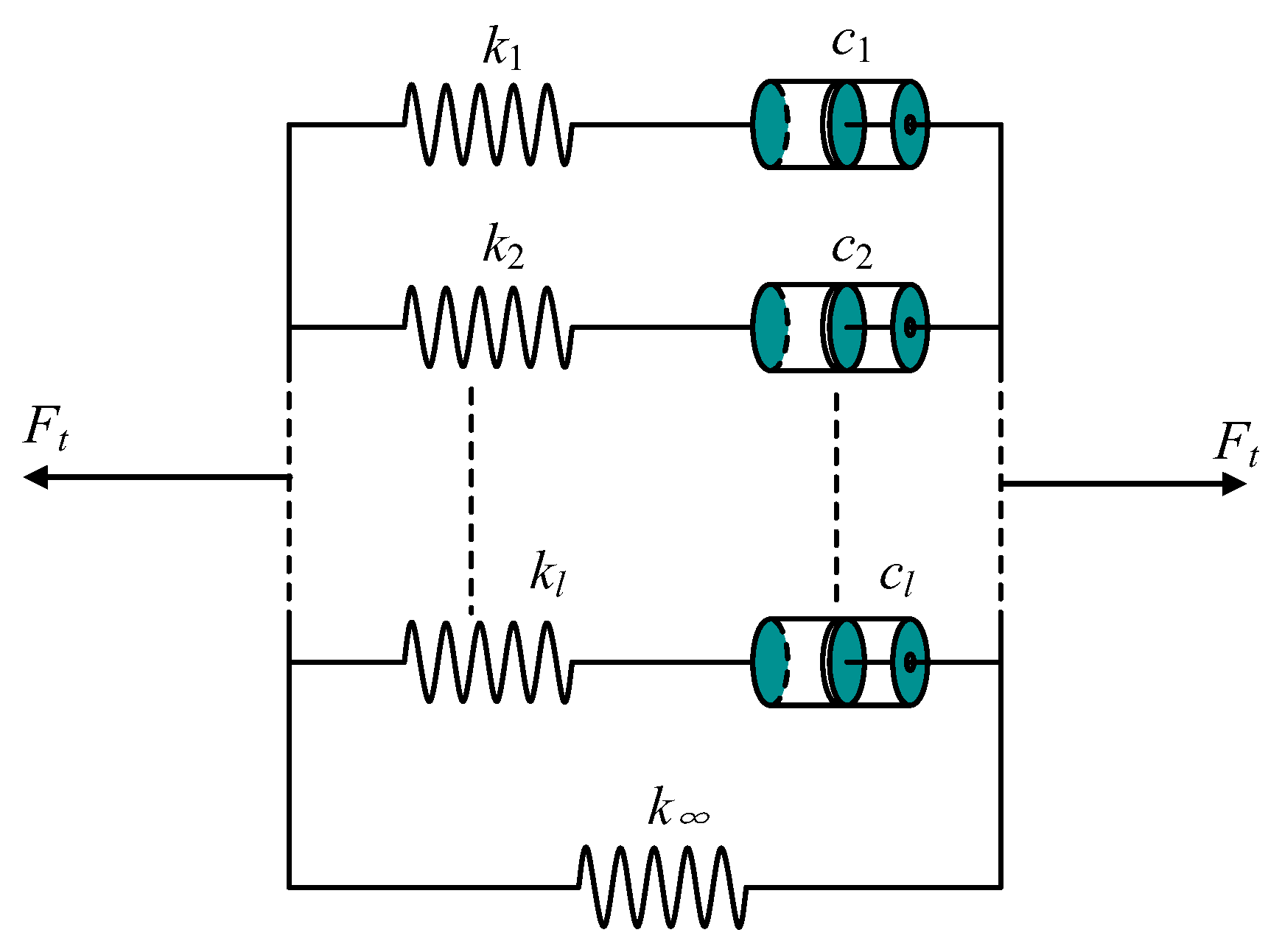
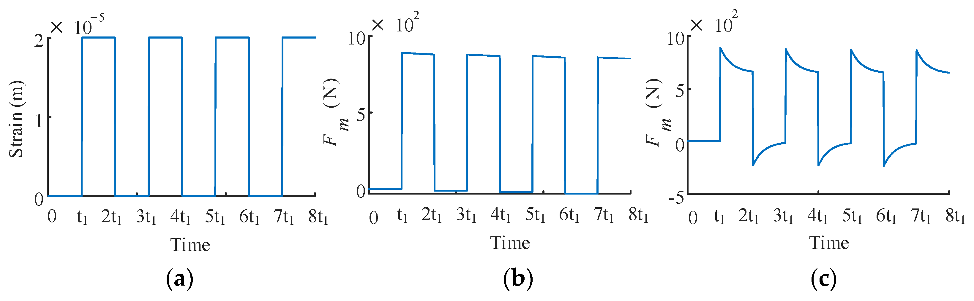
2.1. Viscoelasticity Description
2.2. Formulation of Plastic Tooth Force
2.2.1. Mechanical Model of the Plastic Gear Tooth
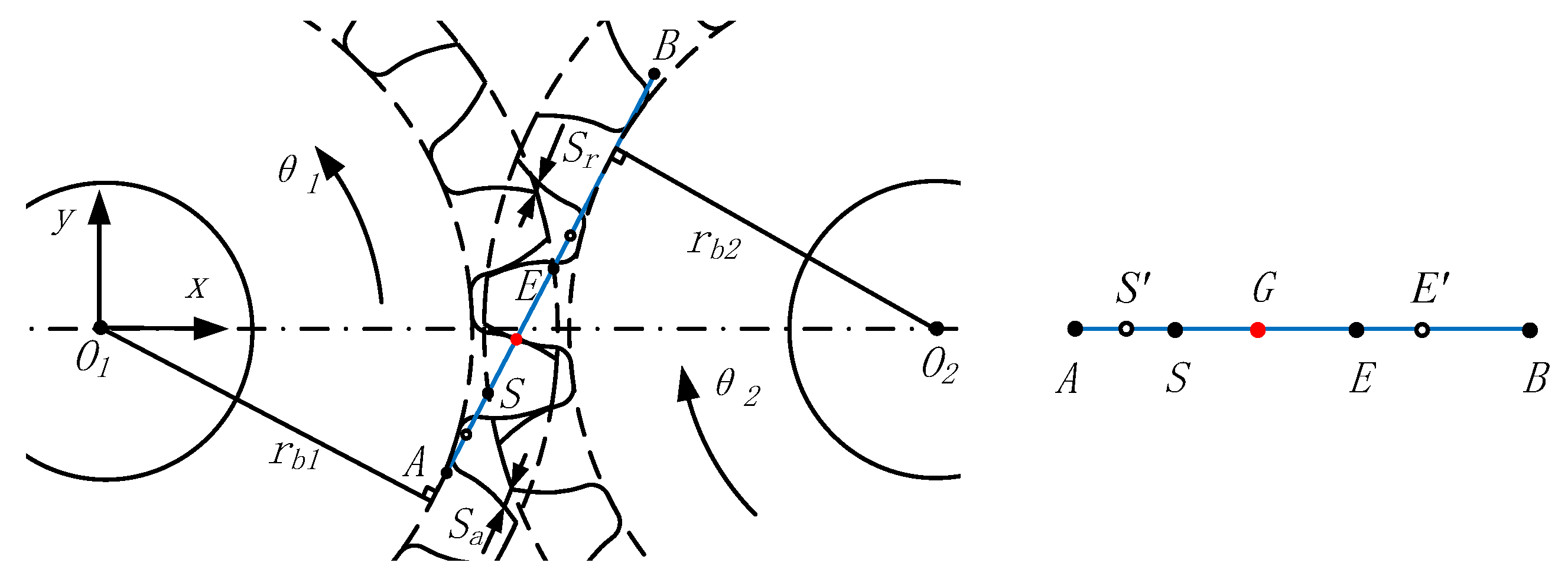
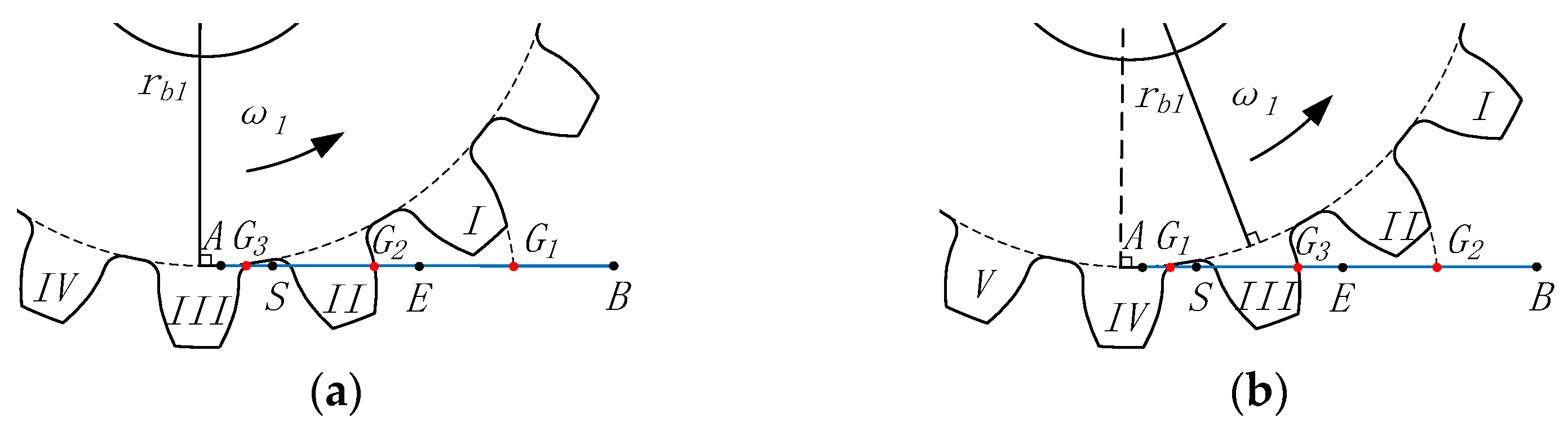
2.2.2. Tooth Deflection Considering the Extended Tooth Contact Effect
- (1)
- When G lies on the SE:
- (2)
- When G lies outside the SE, the total deformation of the gear teeth along the line of action is determined by subtracting the primary clearance from the theoretical deformation due to the presence of the primary clearance.
2.3. Plastic Gear Pair Dynamic Model Considering Material Viscoelasticity and Extended Tooth Contact
3. Simulation Results and Discussion
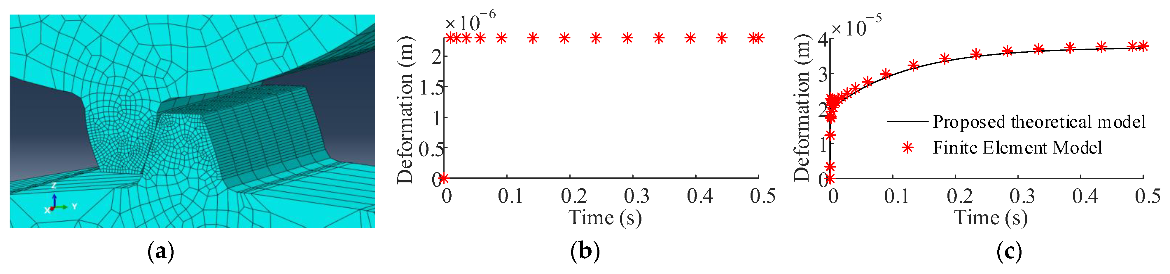
3.1. Model Settings and Validation
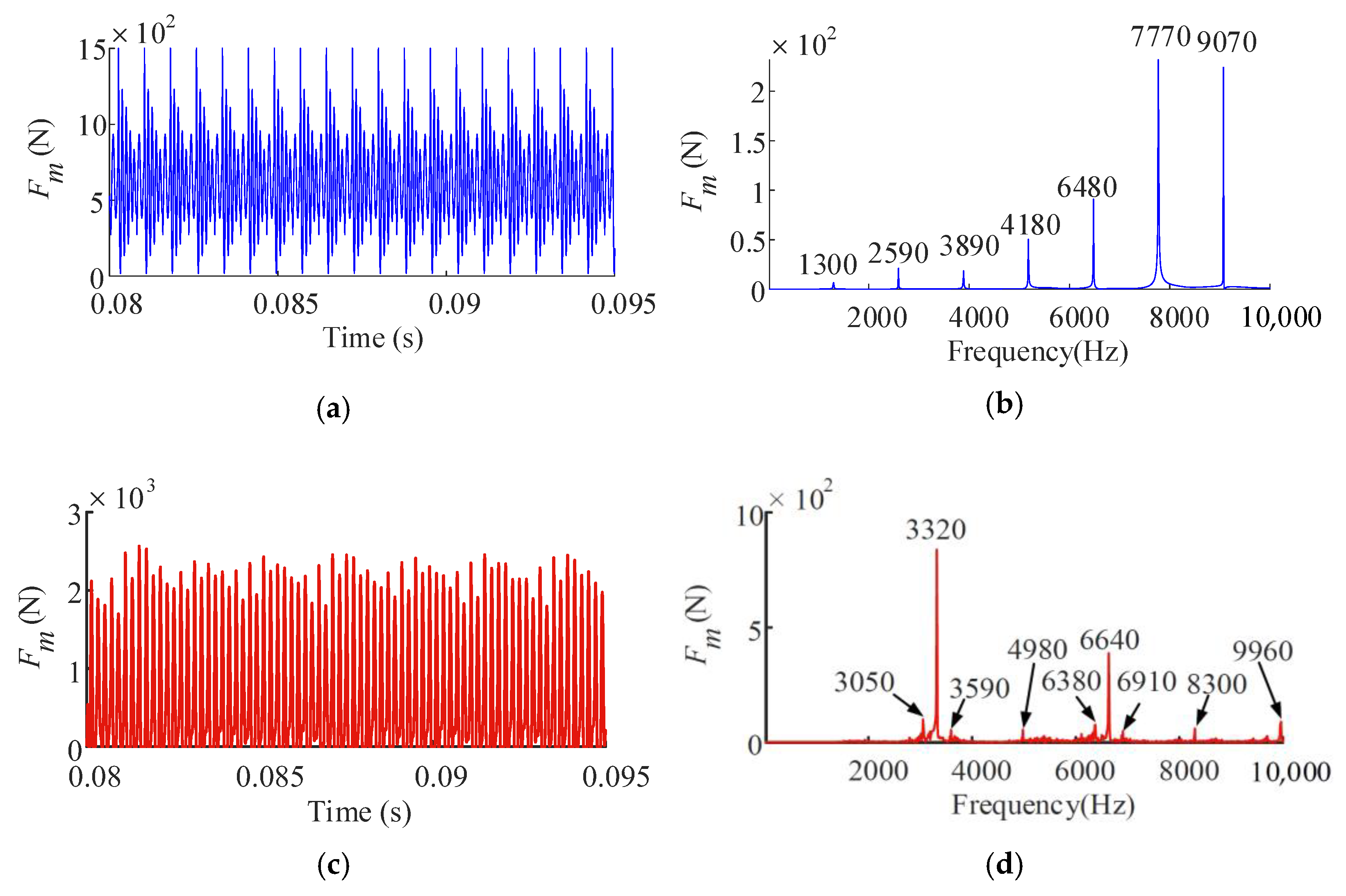
3.2. Frequency-Dependent Tooth Force
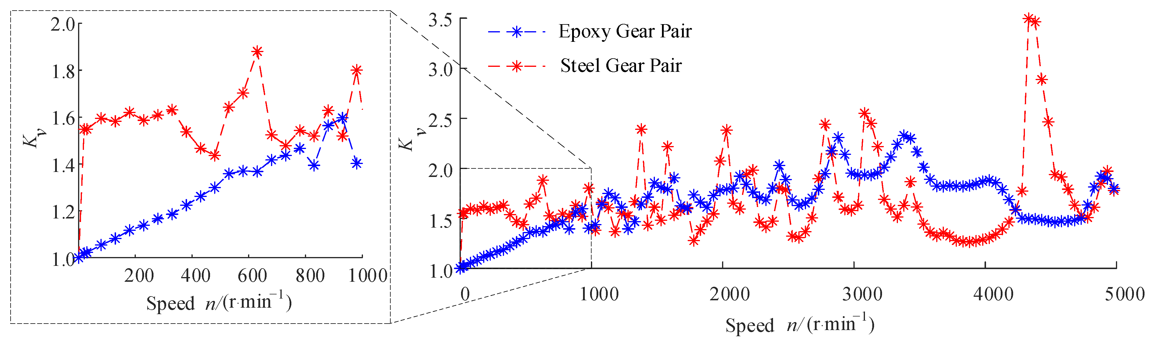
3.3. Dynamic Load Factor
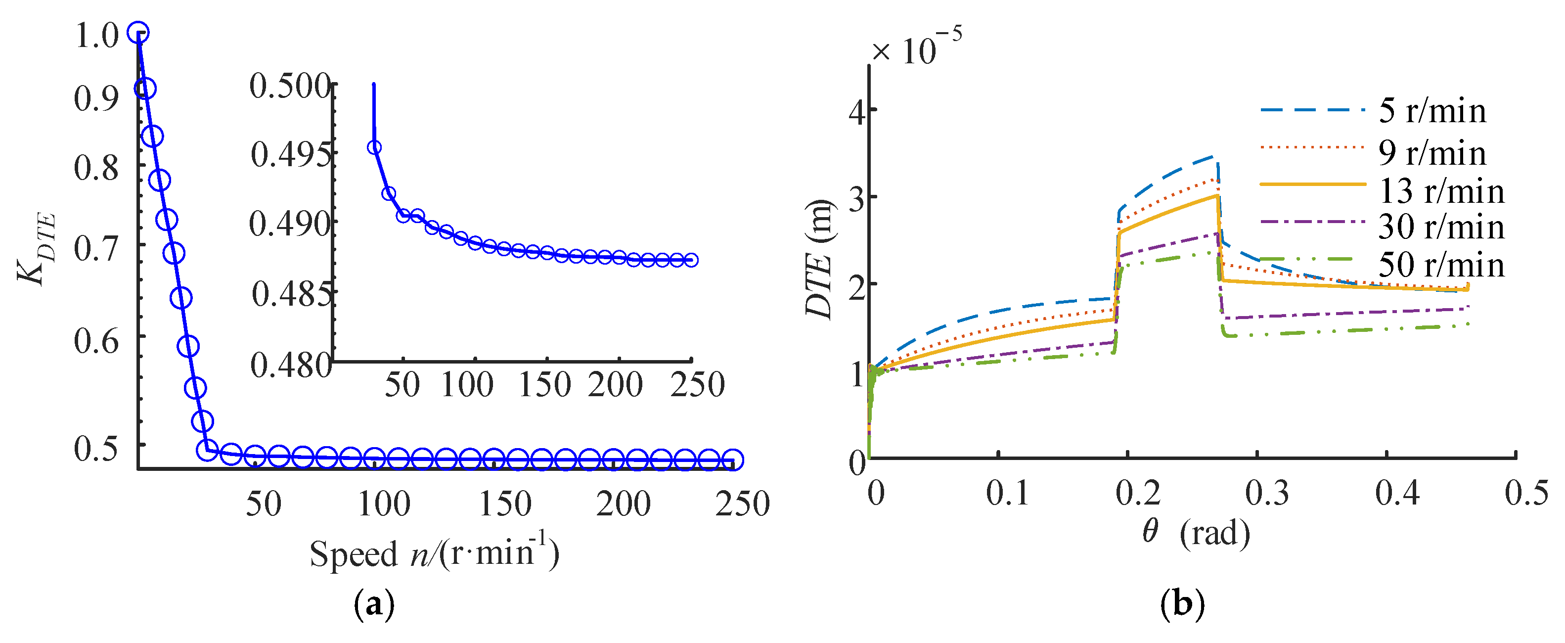
3.4. Dynamic Transmission Error Factor
3.5. Relations between Kv and KDTE
4. Conclusions
- 1.
- The dynamic load factor () of the epoxy gear pair is smaller than that of the steel gear pair at low rotational speeds. With increased rotational speeds, both gear pairs’ curves show some peaks and valleys. However, the rotational speeds corresponding to the peak values of the different gear pairs’ curves are different, and the maximum of the epoxy gear pair is smaller than that of the steel gear pair. This means that the plastic gear can restrain the meshing impact, and it has a generally lower dynamic meshing force than the steel gear pair.
- 2.
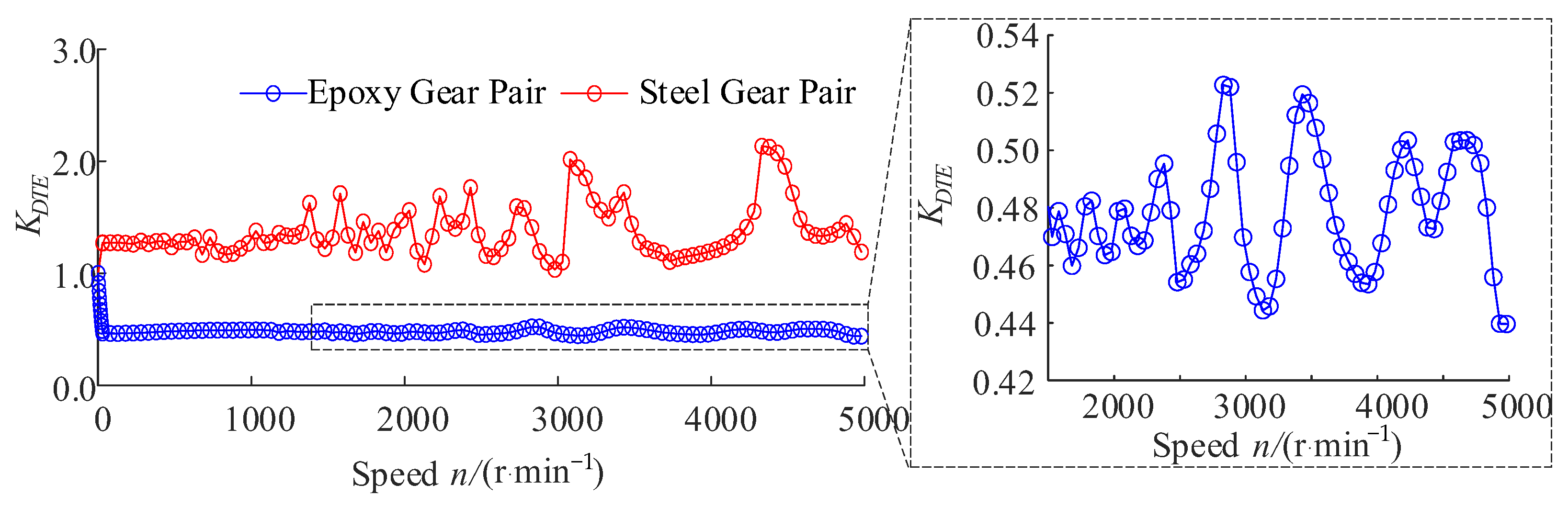
- The dynamic transmission error factor () of the epoxy gear pair is less than one, while the of the steel gear pair is greater than one. Specifically, the of the epoxy gear pair decreases rapidly with the increase of the rotational speed at low speeds. In contrast, it decreases slowly with weak peak–valley characteristics at high speeds. However, the of the steel gear pair shows obvious peak–valley characteristics in the whole speed range. This means that the position accuracy is the weak point of plastic gears, and this feature is significantly affected by the speed, especially when the operating speed is low.
- 3.
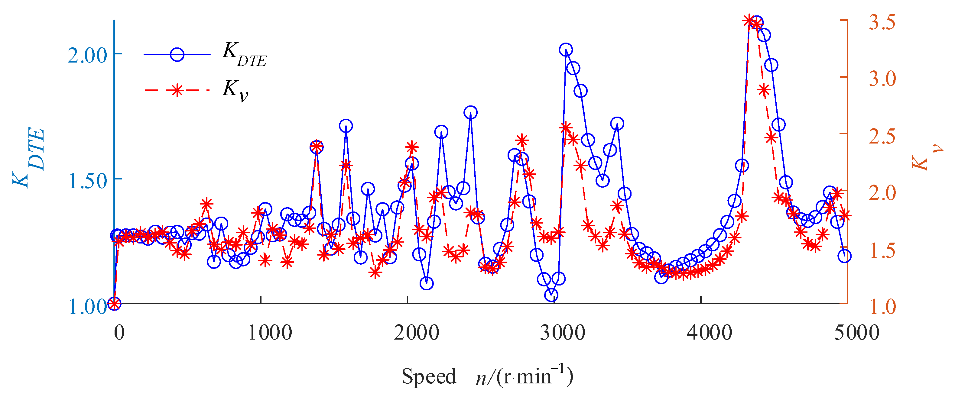
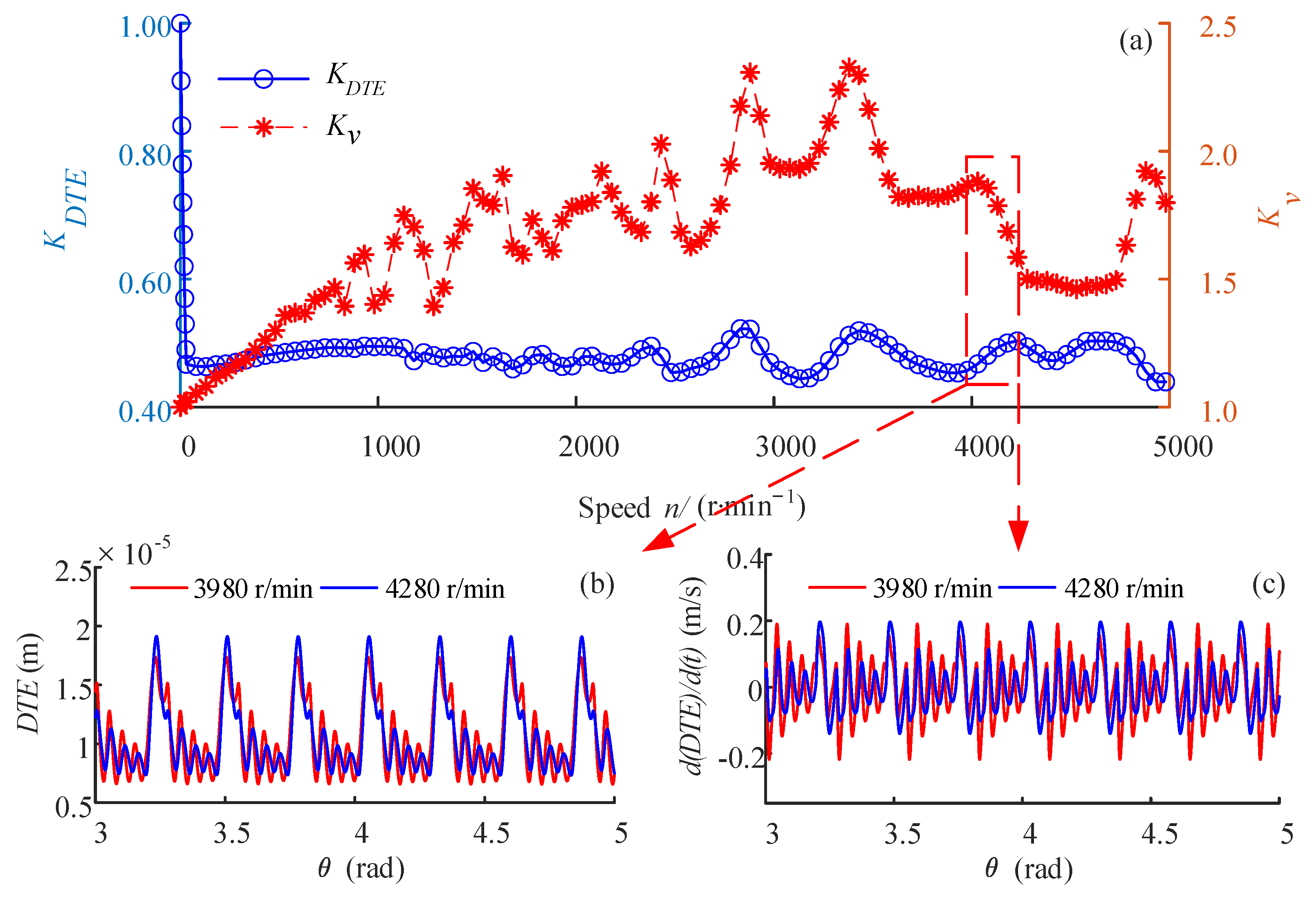
- The of the epoxy gear pair has poor correlation with its , whereas the of the steel gear pair has good correlation with its . This means that the way to indirectly evaluate the dynamic meshing force by measuring the dynamic transmission error, which is often used for metal gears, is less effective for plastic gears.
Author Contributions
Funding
Acknowledgments
Conflicts of Interest
Nomenclature
| α | pressure angle |
| δk | sum of normal deformation of tooth pair k |
| ε | material strain |
| εα | theoretical profile contact ratio (without tooth modification) |
| δ | material stress |
| τi | retardation time for viscoelastic material |
| ∆1, ∆2 | deformation component of standard linear solid model |
| b | tooth width |
| ci | damping component of viscoelastic gear tooth model |
| cjx, cjy | bearing damping of the gear j in the x and y directions |
| gi | statistical weight of viscoelastic material’s Prony series |
| ki | stiffness component of viscoelastic gear tooth model |
| k∞ | stiffness component of viscoelastic gear tooth model |
| kjx, kjy | bearing stiffnesses of the gear j in the x and y directions |
| m | gear module |
| mj | mass of gear j |
| pb | base circle pitch |
| rb | base circle radius |
| t | time |
| Cg | geometric influence coefficient connecting gear tooth stiffness K and material elastic modulus E |
| E | material elastic modulus |
| Fm | total meshing force of gear pair (one or more tooth pairs) |
| Ft | meshing force for single tooth pair |
| Jj | moment of inertia of gear j |
| K | linear displacement stiffness of gear teeth along the line of action |
| K0 | instantaneous tooth stiffness |
| Ka | tooth axial compressive stiffness |
| Kb | tooth bending stiffness |
| Kf | fillet-foundation stiffness of tooth |
| Kh | Hertzian contact stiffness of tooth |
| Ks | tooth shear stiffness |
| Kv | dynamic load factor |
| KDTE | dynamic transmission error factor |
| Sa | primary clearances of the tooth pair in the region of the early approach |
| Sr | primary clearances of the tooth pair in the region of the retarded recess |
| Zj | tooth number of gear j |
References
- Afifi, E.M.; Elshalakny, A.B.; Osman, T.A.; Kamel, B.M.; Zian, H. Investigation of gear performance of MLNGPs as an additive on polyamide 6 spur gear. Fuller. Nano-Tubes Carbon Nanostruct. 2018, 26, 351–359. [Google Scholar] [CrossRef]
- Yu, G.; Liu, H.; Mao, K.; Zhu, C.; Lu, Z. Examination on the wear process of polyformaldehyde gears under dry and lubricated conditions. Friction 2021, 9, 538–550. [Google Scholar] [CrossRef]
- Hasl, C.; Illenberger, C.; Oster, P.; Tobie, T.; Stahl, K. Potential of oil-lubricated cylindrical plastic gears. J. Adv. Mech. Des. Syst. Manuf. 2018, 12, 17–26. [Google Scholar] [CrossRef] [Green Version]
- Hoskins, T.; Dearn, K.; Kukureka, S.N.; Walton, D. Acoustic noise from polymer gears—A tribological investigation. Mater. Des. 2011, 32, 3509–3515. [Google Scholar] [CrossRef]
- Velex, P.; Ajmi, M. On the modelling of excitations in geared systems by transmission errors. J. Sound Vib. 2006, 290, 882–909. [Google Scholar] [CrossRef]
- Tsai, M.H.; Tsai, Y.C. A method for calculating static transmission errors of plastic spur gears using FEM evaluation. Finite Elem. Anal. Des. 1997, 27, 345–357. [Google Scholar] [CrossRef]
- Karimpour, M.; Dearn, K.D.; Walton, D. A kinematic analysis of meshing polymer gear teeth. Proc. Inst. Mech. Eng. Part L J. Mater. Des. Appl. 2010, 224, 101–115. [Google Scholar] [CrossRef]
- Meuleman, P.K.; Walton, D.; Dearn, K.D.; Weale, D.J.; Driessen, I. Minimization of transmission errors in highly loaded plastic gear trains. Arch. Proc. Inst. Mech. Eng. Part C J. Mech. Eng. Sci. 2007, 221, 1117–1129. [Google Scholar] [CrossRef]
- Atanasiu, V.; Doroftei, I.; Iacob, M.R.; Leohchi, D. Nonlinear Dynamics of Steel/Plastic Gears of Servomechanism Structures. Mater. Plast. 2011, 48, 98–103. [Google Scholar]
- Lin, A.D.; Kuang, J.H. The Bending and Surface Contact Stress Variations in a Mating Plastic Gear Pair. In Proceedings of the ASME International Design Engineering Technical Conferences and Computers and Information in Engineering Conference, Las Vegas, NV, USA, 4–7 September 2007; pp. 263–271. [Google Scholar]
- Lin, A.D.; Kuang, J.H. Dynamic interaction between contact loads and tooth wear of engaged plastic gear pairs. Int. J. Mech. Sci. 2008, 50, 205–213. [Google Scholar] [CrossRef]
- Duan, F.; Hu, Q.; Xie, C. Vibration characteristics of steel/plastic gear combined planetary transmission. J. Mech. Eng. 2010, 46, 62–67. [Google Scholar] [CrossRef]
- Brinson, H.F.; Brinson, L.C. Polymer Engineering Science and Viscoelasticity: An Introduction, 2nd ed.; Springer: New York, NY, USA, 2015. [Google Scholar]
- Letzelter, E.; de Vaujany, J.P.; Chazeau, L.; Guingand, M. Quasi-static load sharing model in the case of Nylon 6/6 cylindrical gears. Mater. Des. 2009, 30, 4360–4368. [Google Scholar] [CrossRef]
- Cathelin, J.; Letzelter, E.; Guingand, M. Experimental and Numerical Study of a Loaded Cylindrical PA66 Gear. J. Mech. Des. 2013, 135, 041007. [Google Scholar] [CrossRef]
- Cathelin, J.; Guingand, M.; Vaujany, J.-P. Experimental and numerical study of a loaded cylindrical glass fibre reinforced PA6 gear. In Proceedings of the 2014 International Gear Conference, Lyon, France, 26–28 August 2014; pp. 138–147. [Google Scholar]
- Chen, Z.; Shao, Y. Dynamic simulation of spur gear with tooth root crack propagating along tooth width and crack depth. Eng. Fail. Anal. 2011, 18, 2149–2164. [Google Scholar] [CrossRef]
- Lin, H.; Wang, J.; Oswald, F.B.; Coy, J. Effect of extended tooth contact on the modeling of spur gear transmissions. Gear Technol. 1994, 11, 18–25. [Google Scholar]
- Vuoristo, T.; Kuokkala, V.-T. Creep, recovery and high strain rate response of soft roll cover materials. Mater. Des. 2002, 34, 493–504. [Google Scholar] [CrossRef]
- Qin, D.; Jia, H. Hybrid dynamic modeling of shearer’s drum driving system and the influence of housing topological optimization on the dynamic characteristics of gears. J. Adv. Mech. Des. Syst. Manuf. 2018, 12, 17–00457. [Google Scholar] [CrossRef] [Green Version]
- Liu, Z.; Oswald, J.; Belytschko, T. XFEM modeling of ultrasonic wave propagation in polymer matrix particulate/fibrous composites. Wave Motion 2013, 50, 389–401. [Google Scholar] [CrossRef]
- Bruyère, J.; Gu, X.; Velex, P. On the analytical definition of profile modifications minimising transmission error variations in narrow-faced spur and helical gears. Mech. Mach. Theory 2015, 92, 257–272. [Google Scholar] [CrossRef]
- Hotait, M.A.; Kahraman, A. Experiments on the relationship between the dynamic transmission error and the dynamic stress factor of spur gear pairs. Manuf. Technol. Mach. Tool 2013, 70, 116–128. [Google Scholar] [CrossRef]


| Z1/Z2 | m (mm) | b (mm) | α (°) | εα | kxj, kyj (N/m) | cxj, cyj (Ns/m) |
|---|---|---|---|---|---|---|
| 23/64 | 3 | 20 | 20 | 1.69 | 7.8 × 10¹⁰ | 1.57 × 10⁵ |
| Parameter | Value | Parameter | Value | Parameter | Value |
|---|---|---|---|---|---|
| ν (Gpa) | 5.205 | g1 | 0.3786 | τ1 | 7.321 × 10⁻⁷ |
| G0 (Gpa) | 1.4818 | g2 | 0.3134 | τ2 | 1.163 × 10⁻⁴ |
| E0 (Gpa) | 4.06011 | g3 | 0.1470 | τ3 | 0.06407 |
| ρ (g/cm3) | 1.18 | g4 | 0.0738 | τ4 | 463.4 |
| Parameter | Value | Parameter | Value | Parameter | Value |
|---|---|---|---|---|---|
| k∞ | 8.89 × 10⁶ (N/m) | k2 | 3.19 × 10⁷ (N/m) | c3 | 9.60 × 10⁵ (N·s/m) |
| k1 | 3.86 × 10⁷ (N/m) | c2 | 3.71 × 10³ (N·s/m) | k4 | 7.52 × 10⁶ (N/m) |
| c1 | 28.26 (N·s/m) | k3 | 1.49 × 10⁷ (N/m) | c4 | 3.48 × 10⁹ (N·s/m) |
Disclaimer/Publisher’s Note: The statements, opinions and data contained in all publications are solely those of the individual author(s) and contributor(s) and not of MDPI and/or the editor(s). MDPI and/or the editor(s) disclaim responsibility for any injury to people or property resulting from any ideas, methods, instructions or products referred to in the content. |
© 2023 by the authors. Licensee MDPI, Basel, Switzerland. This article is an open access article distributed under the terms and conditions of the Creative Commons Attribution (CC BY) license (https://creativecommons.org/licenses/by/4.0/).
Share and Cite
Jia, H.; Zhang, J.; Xu, X. Dynamic Modeling and Analysis of Epoxy Gear Considering Material Viscoelasticity. Machines 2023, 11, 76. https://doi.org/10.3390/machines11010076
Jia H, Zhang J, Xu X. Dynamic Modeling and Analysis of Epoxy Gear Considering Material Viscoelasticity. Machines. 2023; 11(1):76. https://doi.org/10.3390/machines11010076
Chicago/Turabian StyleJia, Hanjie, Jiyong Zhang, and Xiangyang Xu. 2023. "Dynamic Modeling and Analysis of Epoxy Gear Considering Material Viscoelasticity" Machines 11, no. 1: 76. https://doi.org/10.3390/machines11010076