1. Introduction
Aeroelastic phenomena in turbomachinery is an important topic of research which brings together the interest of both industry and academia. Industry new design trends are required to follow the need for reducing fuel consumption and improving efficiency, moving the blade configurations closer to their structural limits. This makes the onset of vibratory phenomena a much more critical issue due to the increased risk of experiencing high-cycle fatigue problems, with the associated increment in maintenance costs. On the academia side, the associated problems are extremely challenging because of their multiphysics nature (involving aerodynamics, solid mechanics, nonlinear friction, etc.), the complexity of the bladed-disk geometry, and the difficulties associated with its accurate numerical simulation.
Mechanical vibrations in turbomachinery are produced mainly by two sources (see, e.g., the reviews [
1,
2]): (i) forced response (FR), when the system vibrates in a synchronous way, with a frequency locked to that of an existing external excitation force (typically coming from the wakes of the upstream vanes), or (ii) flutter, which corresponds to an aerodynamic instability, and the system vibrates asynchronously with its own elastic modal frequency.
There are currently well-established standard methodologies that allow to accurately compute the effect of FR and flutter in a turbomachinery rotor, using FEM modal analyses combined with linearized CFD flow calculations [
3,
4]. These methodologies still consider the different sources of vibration independently and, when both effects are present on the solution, the linear superposition of both vibration amplitudes is assumed. However, some recent theoretical studies using mass–spring models and asymptotically reduced-order models (ROM) have shown that this superposition could lead to a too conservative prediction of the blade displacements [
5,
6].
Another factor crucial for the correct estimation of the final vibration amplitude of a turbomachinery rotor is the mistuning, which measures the small differences among the sectors of a bladed disk. These systems are normally designed assuming that all sectors are perfectly identical, but small differences that break the cyclic symmetry, caused by the material imperfections or wear due to operation conditions, are always present and unavoidable. Mistuning is typically very small, but can result in a considerable change in the vibration characteristics with respect to those of the ideal (tuned) rotor. Typically, mistuning has a negative effect on the forced response vibration problem, producing the localization and the amplification of the vibration in a reduced number of blades [
7,
8], while, on the other hand, it has a stabilizing effect on the flutter response of an unstable bladed disk, coupling the different TW modes and decreasing the instability level [
9,
10].
Because of the random nature of these unavoidable differences (often called “intrinsic” or “natural” mistuning), the introduction of an intentional mistuning pattern, added to the intrinsic mistuning, has been studied with two main objectives: the reduction in the sensitivity of the system to the intrinsic mistuning, which makes the detailed system response practically unpredictable [
11,
12,
13], and the increase in the aerodynamic stability of the system [
14].
The study of the interaction between FR and flutter is one of the objectives of the European project Advanced Research Into Aeromechanical Solutions (ARIAS) [
15]. In the framework of this project, a realistic low-pressure turbine (LPT) rotor was tested on a high-speed cold-flow wind tunnel at the Centro de Tecnologías Aeronáuticas (CTA), located in Zamudio (Spain). The rotor, apart from being aerodynamically unstable, was excited using magnets to introduce forcing with a prescribed wavenumber, allowing the study of the combined effect of FR and flutter. Additionally, several intentional mistuning patterns were also implemented on the LPT rotor in order to evaluate their effect in the presence of FR and flutter (see [
16] for a more detailed description of the experiment).
The vibrational response of the rotor with intentional mistuning measured at the CTA experiments showed an anomalous behavior. There were two resonance peaks in the frequency sweeps (associated to the two types of blades present in the rotor), but, contrary to what was expected, the two peaks had very different amplitudes, and, surprisingly, some blades showed a similar vibration level at both frequencies. This gave rise to many problems in the experimental identification of tuned/mistuned blades. In the experiment, a blade was considered tuned or mistuned according to the frequency of its highest peak, and, thus, the blades showing two similar peaks in the frequency sweep were frequently wrongly identified, leading to the somewhat shocking result that the experimentally detected mistuning pattern was very different from the one implemented.
This unexpected blade response is analyzed in this work using a very simple ROM that contains only the minimal set of traveling-wave (TW) modes that are coupled by the intentional mistuning. The asymptotic mistuning model (AMM) methodology has been previously applied to successfully reproduce the response of a similar realistic LPT rotor [
17], and it is used here to derive the ROM that explains the results obtained in the experimental campaign at CTA.
This paper is organized as follows. First, the experimental results obtained for the tuned (no intentional mistuning) LPT configuration with the simultaneous effect of FR and flutter are reported and analyzed. Then, for the two different intentional mistuning patterns tested at the CTA: (i) the frequency sweep measurements are presented and discussed in detail, and (ii) the asymptotic ROM is derived, the model and the experimental results are compared, and an explanation for the unexpected blade vibration behavior is proposed.
2. Tuned Case
As part of the ARIAS project, an unstable LPT rotor was tested in a high-speed cold-flow wind tunnel at CTA [
15]. The rotor had 144 blades equipped with a magnet on the top, and there were also a number of magnets fixed to the casing in order to produce an external excitation with TW form and with a prescribed wavenumber. The rotation speed was adjusted to excite the first modal family of the rotor in order to study the combined effect of flutter and forced response [
16].
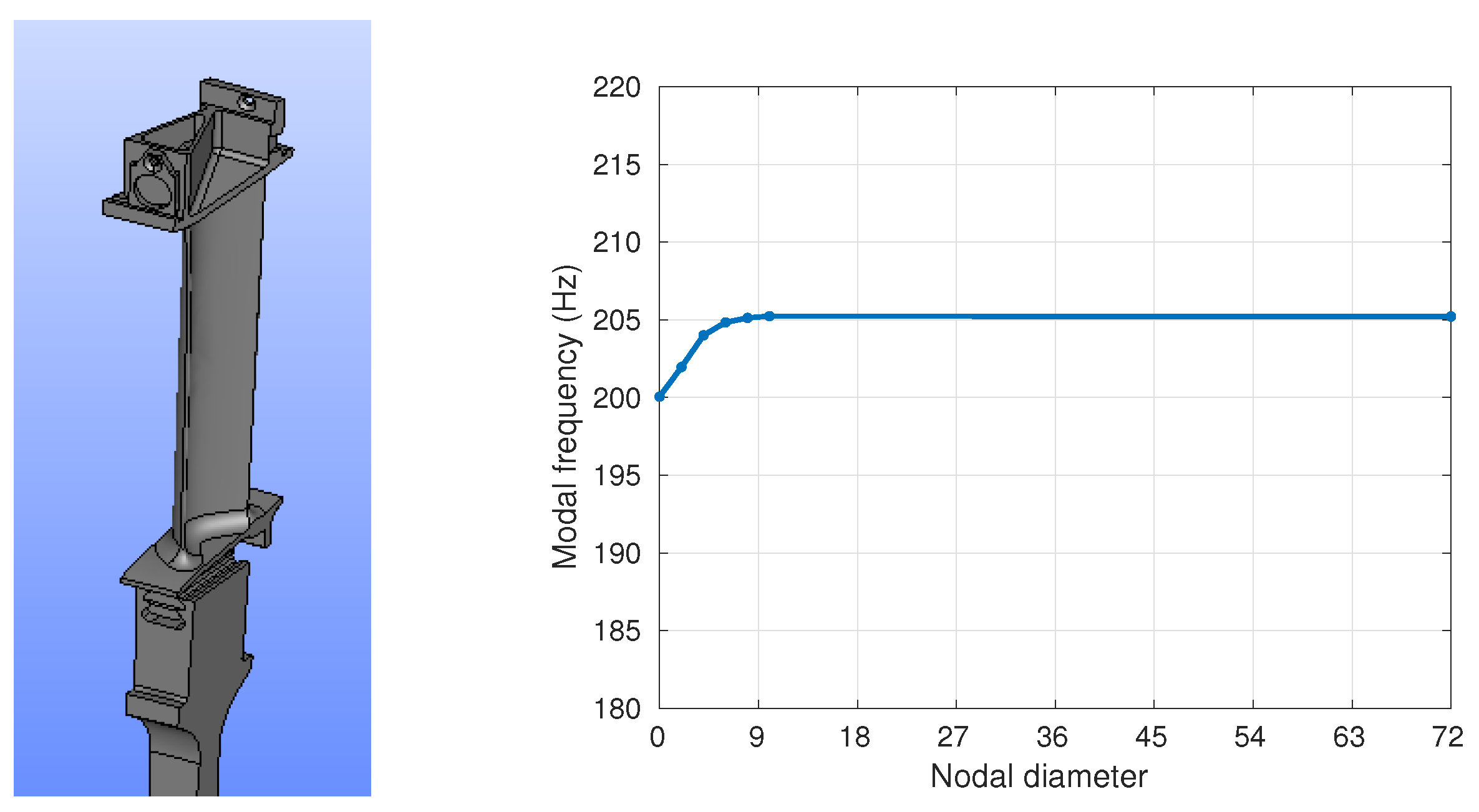
The frequency analysis of the first modal family (flap) computed using a FEM model with around 250,000 DOFs per sector is presented in
Figure 1 for the nominal rotation speed. It shows a very flat curve, indicatingthat the bladed-disk vibration modes are practically blade-alone modes.
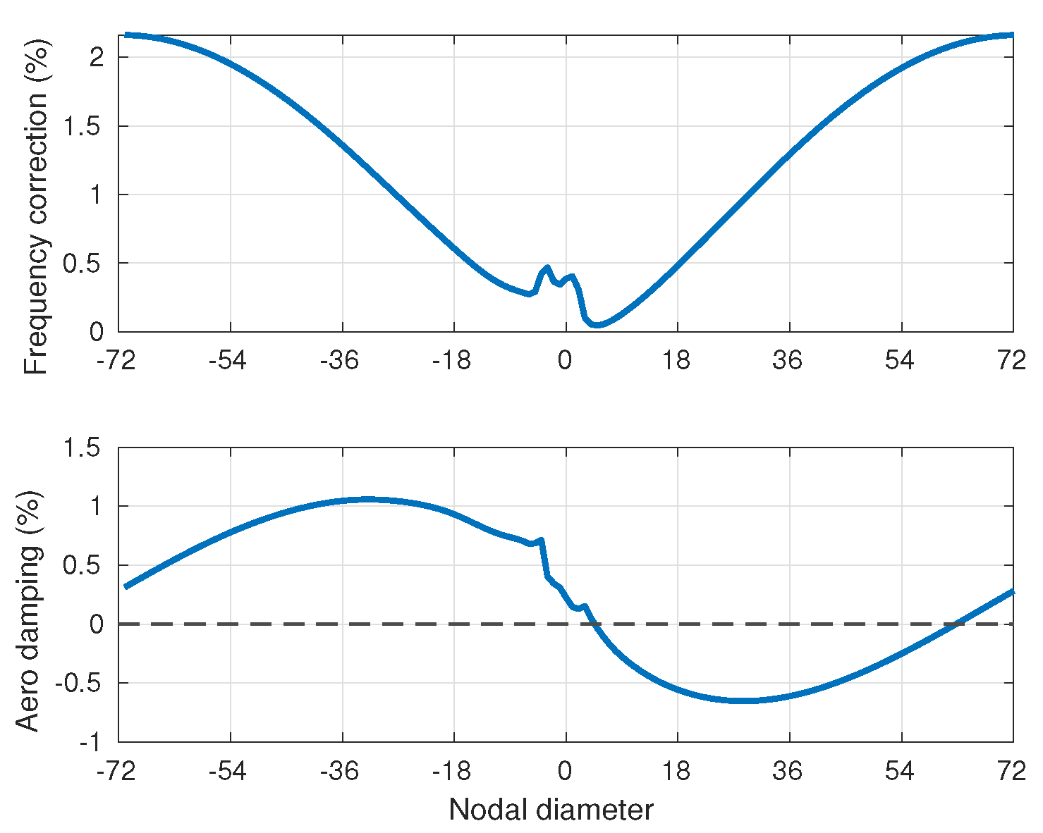
CFD simulations of the linearized aerodynamic problem were also performed to obtain the corresponding aerodynamic stability coefficients using the in-house ITP Aero code Must-L [
18]. The aerodynamic damping and frequency correction coefficients for the nominal rotation speed are shown in
Figure 2. The LPT rotor is clearly unstable: there is a wide range of nodal diameters with negative aerodynamic damping, which can experience flutter and the most unstable TW, that is, the minimum of the aerodynamic damping curve in
Figure 2, corresponds to ND = 25.
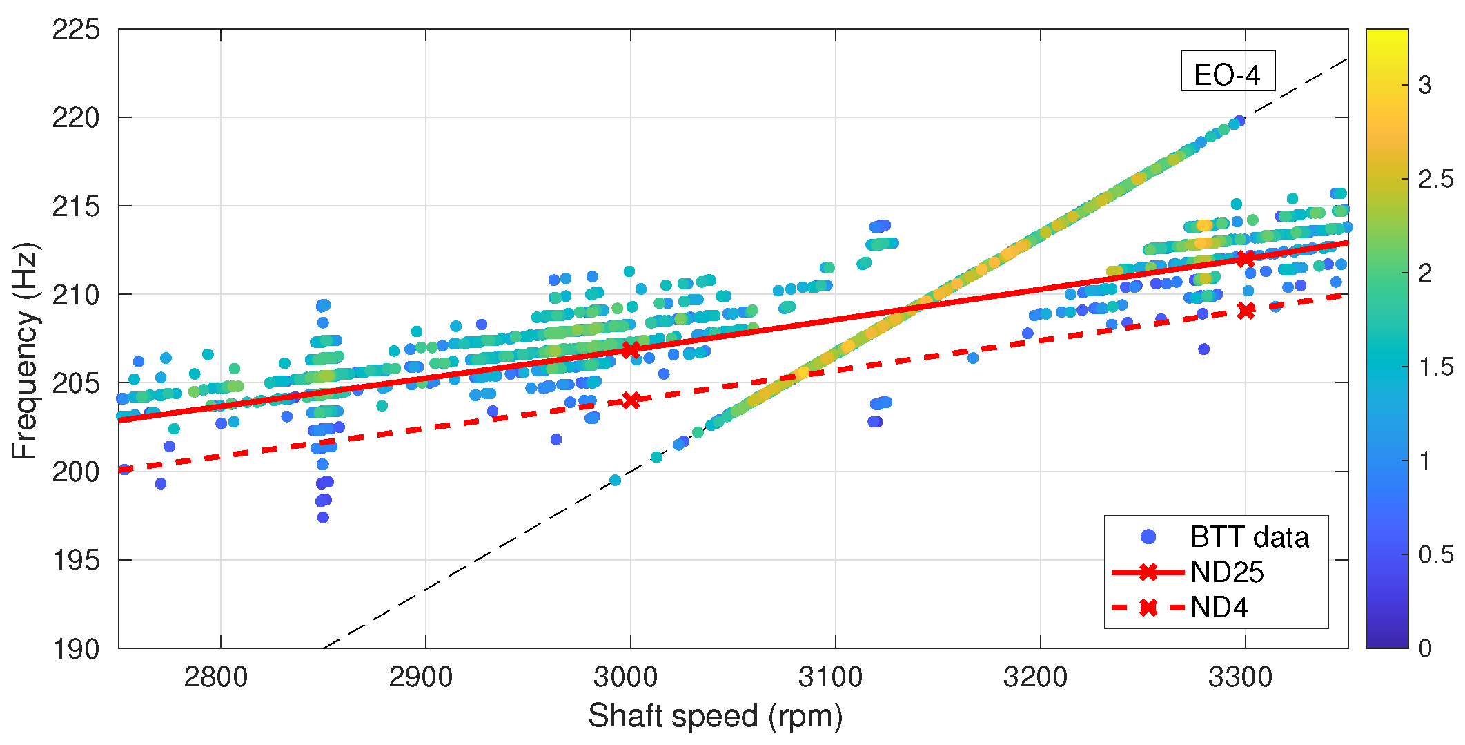
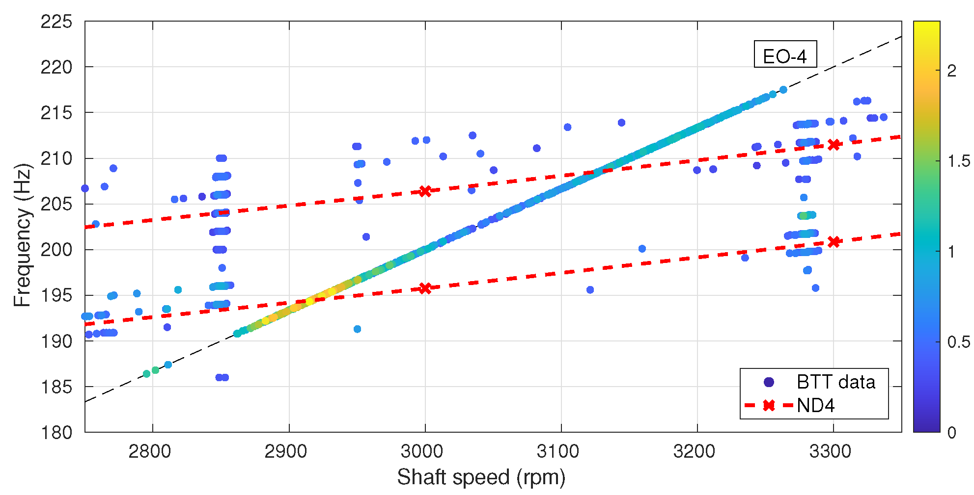
The experimental data shown in
Figure 3 are Blade Tip Timing (BTT) measurements generated by Rolls-Royce company as part of their activity in the ARIAS project [
19]. Several rotation speed ramps are plotted for the case of four magnets mounted on the casing that produce a TW excitation with engine order 4 (EO4). There is a clear resonance crossing with the first modal family that is in good agreement with the modal FEM results. The dashed line corresponds to the computed ND = 4 modal frequency, and its intersection with the EO4 FR line is very close to the maximum amplitude (light yellow color in
Figure 3). Away from the resonance, the flutter instability is seen with a vibration amplitude that is comparable to that of the FR (yellow color dots), and with a frequency very similar to that of the most unstable TW, with ND = 25 (solid line), which is about 5Hz above that of the directly forced TW with ND = 4 (see
Figure 1).
The rotor has of course some small intrinsic mistuning, and there are also some unsteady ramp effects that somehow contaminate the data in
Figure 3, but it clearly shows that FR dominates near resonance (with the blade vibration frequency locked to the forcing frequency), that flutter is recovered away from the resonance, and that the resulting total vibration is much lower than the linear superposition of both effects. This nonlinear switching between FR and flutter was first described in [
5] using a mass–spring model with a simple microslip friction force. This particular dynamical behavior is due to the nonlinear character of the friction forces acting at the fir-tree, which provide the required dissipation to counterbalance the energy pumped in by the instability and the external forcing and determine the final vibration level of the blades.
It is also interesting to report that, in the flutter-dominated region, despite the fact that there are many unstable TWs that could appear, it was also seen in the experiments that the TW that is finally selected in the response is always near the most unstable one (TW with ND = 25), and this is also in agreement with existing previous ROM predictions [
20,
21,
22].
3. Intentional Mistuning Pattern [01]
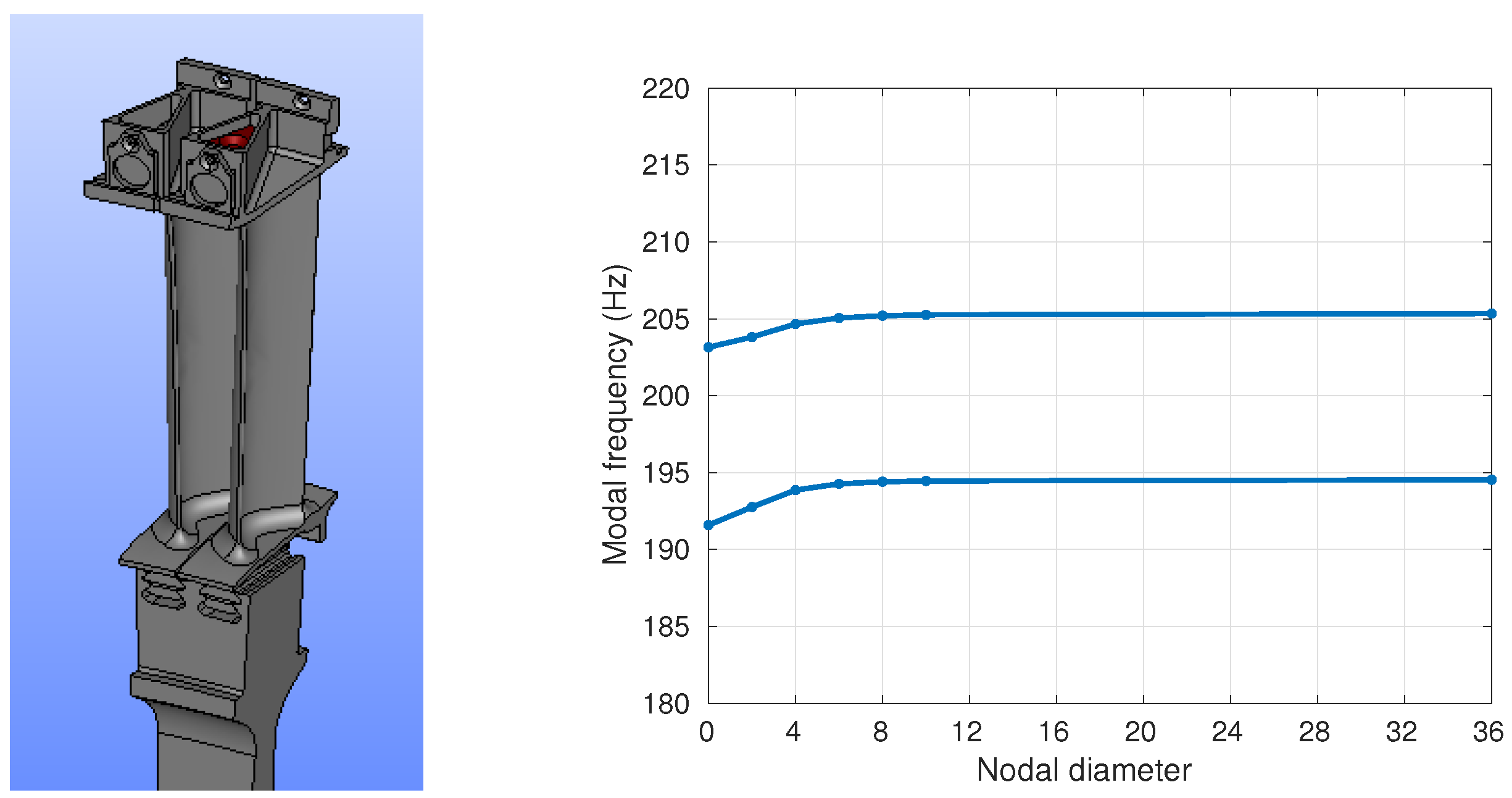
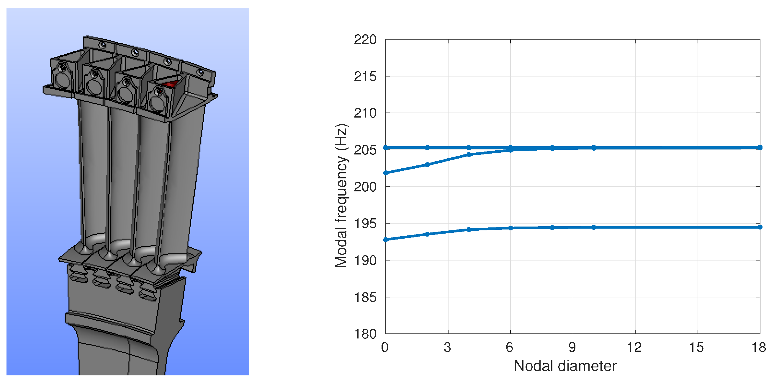
The first intentional mistuning pattern considered, referred to also as the alternate mistuning pattern [01], was implemented by adding a small mass to one of every two blades ([0] = blade with mistuning mass, and [1] = blade with mistuning mass). The mistuning mass was added at the top of the blade, as indicated in
Figure 4.
The mistuned rotor can now be regarded as a tuned rotor but with 144/2 = 72 sectors made of two blades. The FEM modal analysis of the [01] rotor for the nominal rotation speed is presented in
Figure 4, where the effect of the mistuning pattern on the frequencies is just to split them into 2 nearly flat families about 10 Hz apart; the lower-frequency family corresponding to the vibration of the mistuned blades [1] and the higher-frequency family corresponding to the vibration of the tuned blades [0].
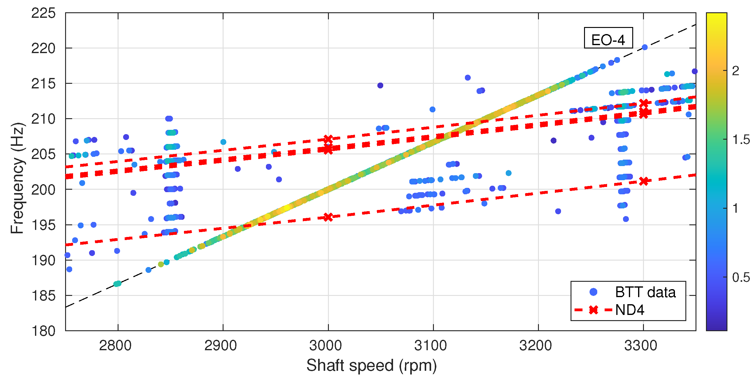
The results of the BTT measurements for the rotor with alternate mistuning are presented in
Figure 5, again for an external forcing with EO4. The flutter amplitude is now very reduced because of the effect of the intentional mistuning pattern. The main effect of the mistuning pattern (with wavenumber 74) is to produce a coupling between the TWs with nodal diameters ND and ND + 74 [
14], and therefore, the most unstable TWs are coupled with the most stable ones (see
Figure 2), resulting in a strong stabilization of the rotor.
With the flutter instability drastically reduced, FR dominates the response of the system. It can be seen that there are now two peaks along the EO4 forcing line that correspond to the excitation of the two TWs with ND = 4 (see
Figure 4). The ND = 4 frequencies from the FEM calculations are marked with dashed lines in
Figure 5 and show a very good agreement with the location of the two maxima of the vibration amplitude.
One would expect that these two peaks, which correspond to the resonance of the two types of blades present in the rotor: [1] = mistuned = lower vibration frequency, and [0] = tuned = higher vibration frequency, would have similar amplitudes. However, taking a closer look at the data in
Figure 5, it can be clearly seen that the two peaks are quite different, with the amplitude of the first peak being much larger than that of the second.
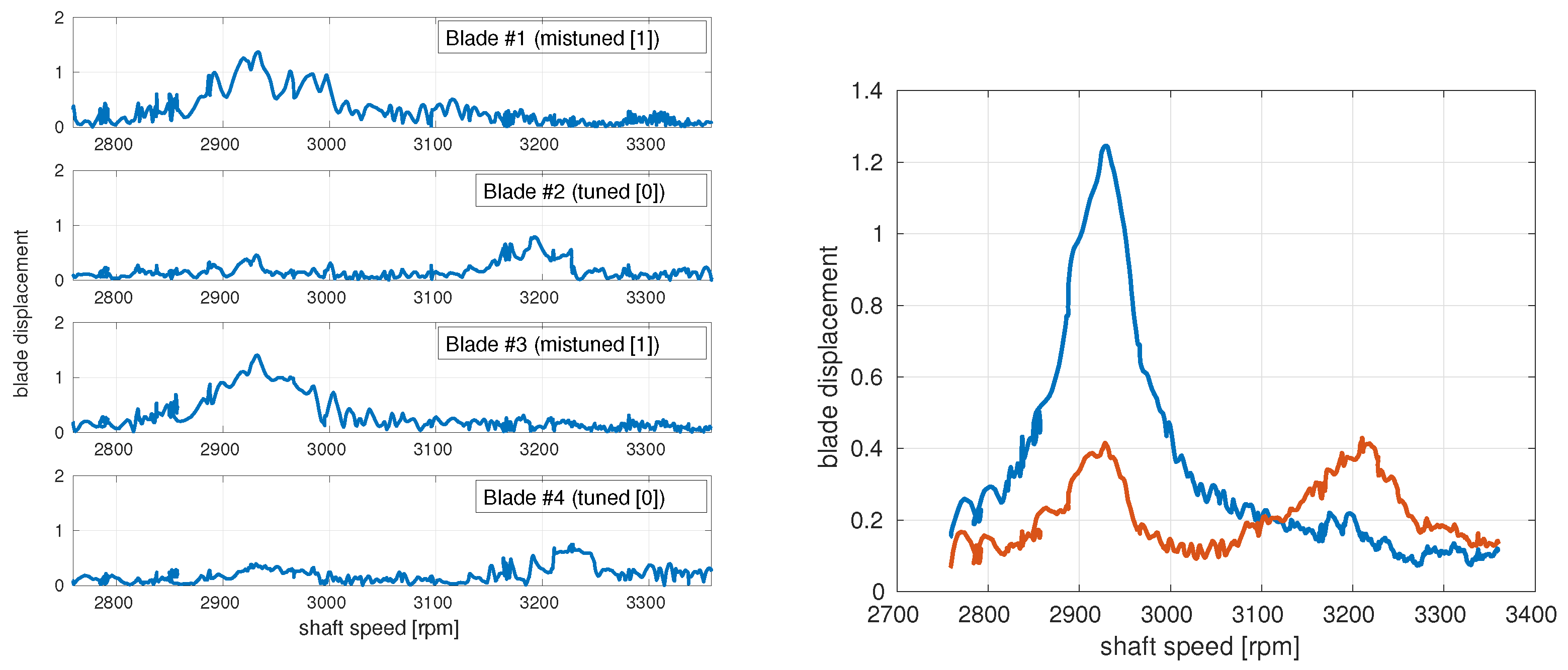
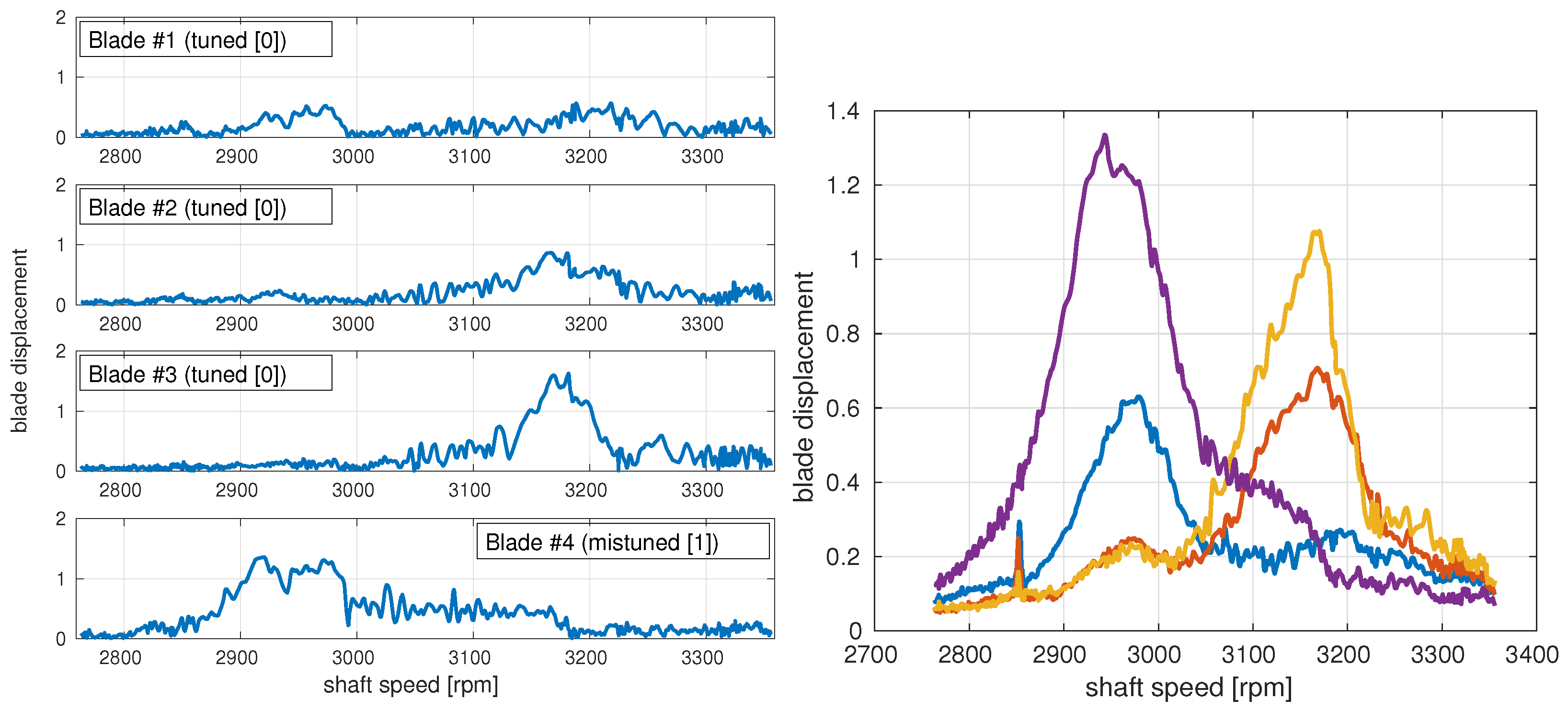
This anomalous behavior of the blade response is more clearly seen in
Figure 6, where the measured displacement of the first 4 individual blades is plotted for a frequency sweep. The mistuned blades [1] present a response made of a strong single peak at the lower frequency, while the tuned blades [0] show two much smaller peaks at both resonances with similar amplitudes. These nonstandard characteristics are even more evident if we consider the averaged displacement of all tuned [0] and mistuned [1] blades (see
Figure 6), where, as expected, the averaging process substantially reduces the noise present in the individual blade measurements.
In order to understand the blade response found in the experiments, a ROM based on the Asymptotic Mistuning Method (AMM) [
23] is used. The basic idea of the method is that the effect of the alternate mistuning (with wavenumber N/2 = 72) is to couple the tuned TW that is directly forced (with ND = EO = 4) with the tuned TW with ND = EO + N/2, and only these two TWs are present in the response of the system. In other words, for an alternate mistuning pattern [01], the response is computed assuming that it is a tuned rotor but with 72 sectors of 2 blades each.
The resulting asymptotic ROM is extremely simple, with only two equations corresponding to the amplitudes of the TWs with ND = EO and EO + N/2, coupled through the mistuning:
Here, and are the frequency and the amplitude of the forcing, and the rest of the parameters that are present in the ROM are the frequencies of the TW modes, and (which include both the structural and the aerodynamic contributions), the frequency split produced by the mistuning masses (), and the small material damping ().
The ROM can be further simplified just by shifting the forcing frequency to the mean value of the mode frequencies (
), scaling all coefficients with the difference of the mode frequencies (
), and fixing the forcing amplitude to have a tuned maximum response equal to 1 (it is a linear system):
The response of the system is governed by the parameter , which is the ratio between the frequency split induced by mistuning and the difference in frequency of the coupled tuned modes. This parameter can be regarded as a measure of the relative importance between mistuning and blade coupling (the elastic and aerodynamic blade coupling effect is contained in the difference of the tuned TW frequencies). With this rescaling, the frequencies of the two tuned TWs involved in the system response are now and .
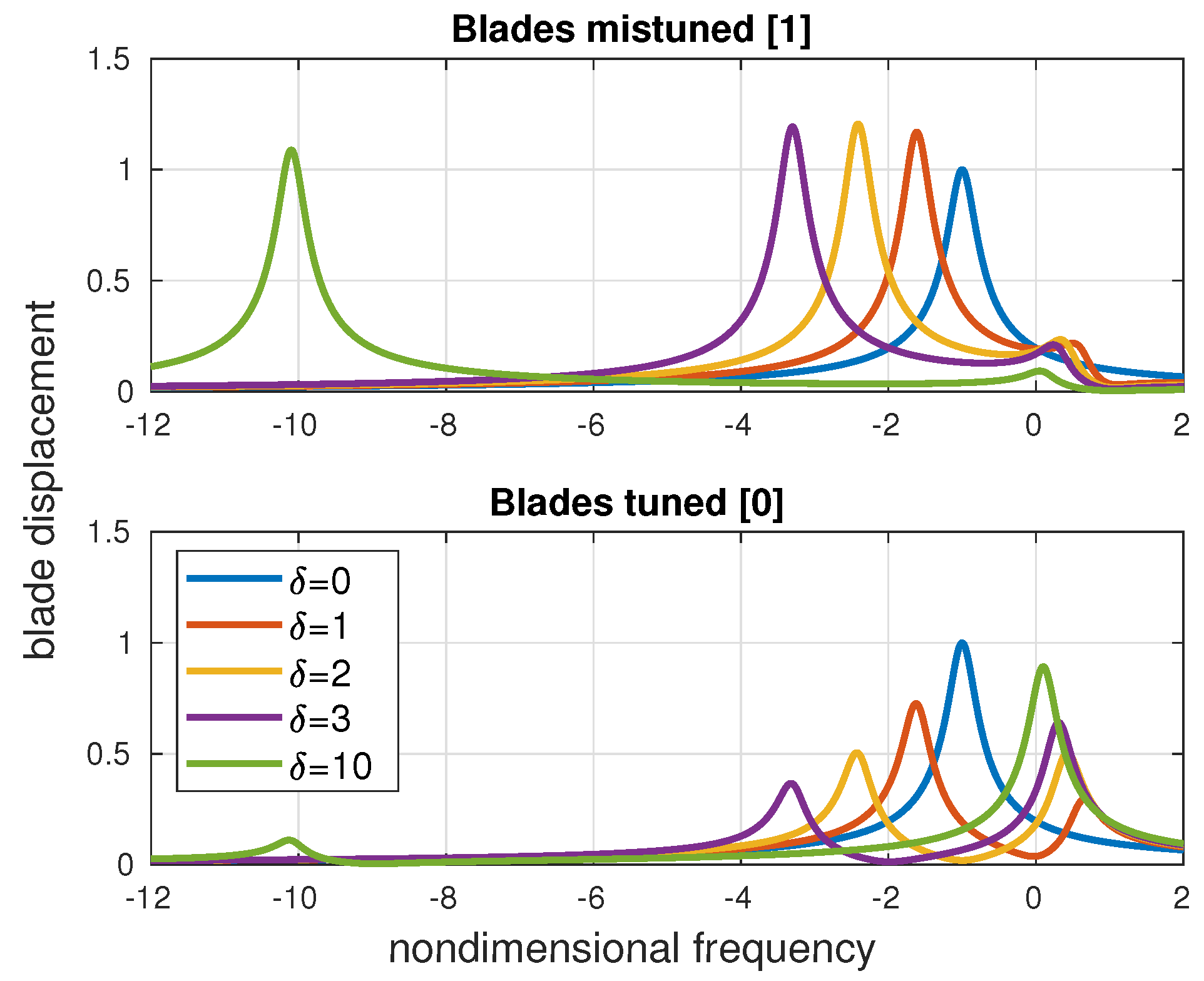
Figure 7 shows the solution of the ROM for different values of the scaled mistuning size
. The vibration of the mistuned blades is represented on the top and the vibration of the tuned blades on the bottom. For large values of
(large mistuning as compared with the tuned TW frequency difference), the response is the expected one: the blades behave as independent, and we have two separated peaks for the tuned and mistuned blades with similar amplitudes. The natural frequencies can be easily computed from the ROM:
and, for
, the mistuned blades frequency decreases as
(because of the added mass), while for the tuned blades, it tends to the mean frequency of the TW modes
.
For moderate values of , when the blade coupling is comparable to the effect of mistuning, the response is more complicated, and the two types of blades show a quite different behavior. As mistuning is increased from the tuned configuration (), a new peak appears at , which corresponds to the onset of the TW with ND = EO + N/2 (excited through mistuning), and moves towards . The response at this peak is basically made of a single TW with small amplitude, and gives, therefore, a small but similar vibration level for both blades. On the other hand, the tuned peak at frequency moves down as is increased. The response at this low-frequency peak consists of the superposition of the directly forced TW (with ND = EO and amplitude close to 1) and a small amount of the TW with ND = EO + N/2 (excited again through mistuning). The combination of these two TWs increases the amplitude of the mistuned blades [1] and reduces that of the tuned ones [0], producing a completely different vibration pattern, as it is observed in the CTA experiment.
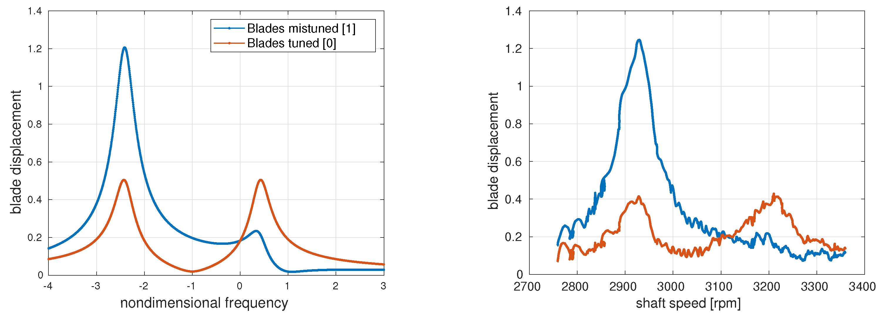
For the particular case of the CTA experiment with the [01] mistuning pattern and an excitation with EO4, the difference between the elastic frequencies of the TW modes with ND = EO = 4 and ND = EO + N/2 = 4 + 72 = −68 can be computed from
Figure 1 to give
Hz. Additionally, the different aerodynamic frequency corrections of the modes produce a difference in frequency of
Hz (obtained from the top plot in
Figure 2). In total, the difference between the two modal frequencies is
Hz. The frequency gap induced by the mistuning can be directly obtained from the FEM modal results in
Figure 4 to be
Hz. This leads to a relative size of mistuning
, and the damping coefficient is set to
, which is the mean value of the aerodamping of the two TWs involved in the response (bottom plot in
Figure 2).
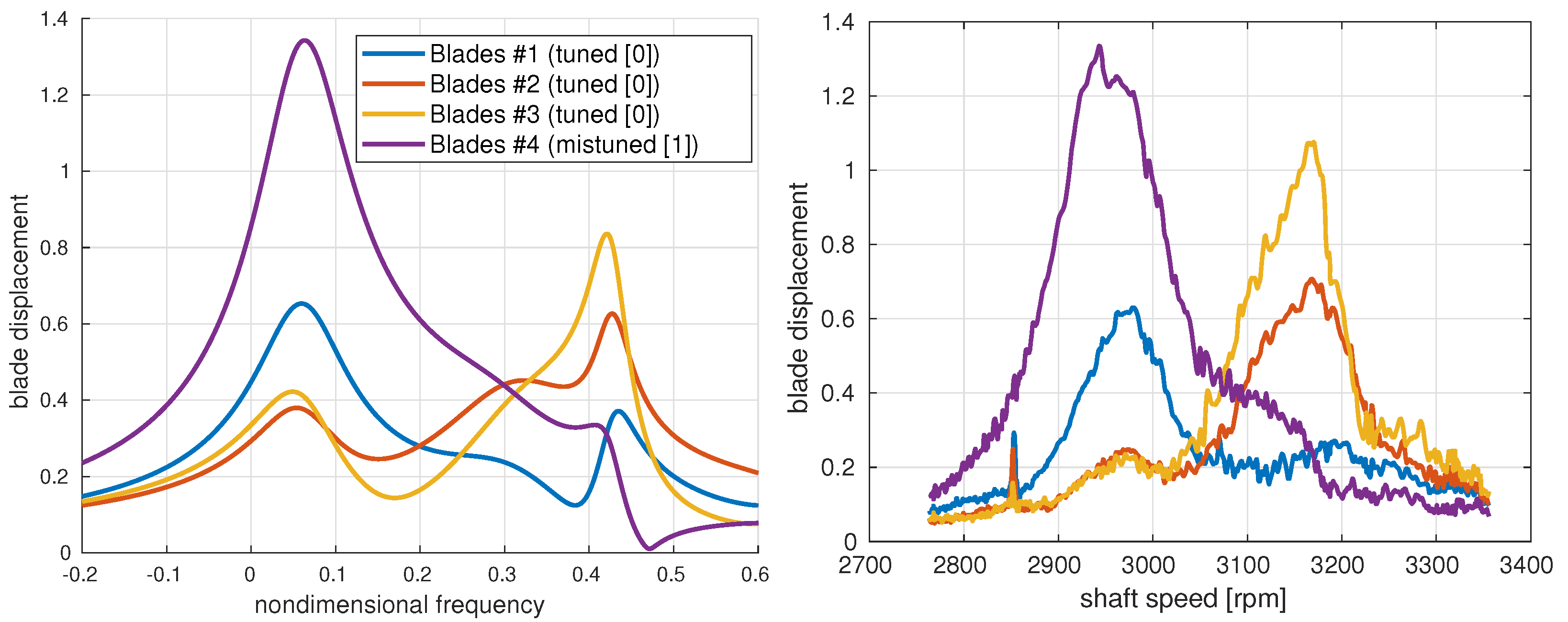
The ROM results corresponding to the above parameters are presented in
Figure 8, together with the experimental averaged blade displacements (already plotted
Figure 6 but included here again to facilitate the comparison). It can be seen that there is a very good agreement between both results. The ROM is clearly able to capture the anomalous blade response seen in the experiment: the mistuned blades present a large single peak, while the tuned blades vibrate in two different peaks with smaller amplitude.
4. Intentional Mistuning Pattern [0001]
A second intentional mistuning pattern was tested at the CTA experiment which included one mistuning mass every four blades [0001]. The natural frequencies for this case are presented in
Figure 9, where a sector made of 4 blades was used for the FEM modal analysis. The effect of the mistuning on the frequencies is again to separate them into 2 groups. The lower-frequency family corresponds to the vibration of the mistuned blades [1], and the 3 families at higher frequency correspond to the vibration of the tuned blades [000].
The BTT measurements corresponding to the mistuning pattern [0001] with a forcing with EO4 are presented in
Figure 10. The same switching between the FR and flutter solutions is observed and, again, the synchronous solution clearly dominates the response near the resonance, with two resonance peaks that are in good agreement with the FEM-computed frequencies (dashed lines in
Figure 10).
The vibration amplitude of the lower-frequency resonance peak (mistuned blades) appears again to be higher than that of the higher-frequency peak (tuned blades). This is more clearly seen in
Figure 11, where the measured displacement of the first 4 blades is plotted together with the averaged displacement of all 4 types of blades present in the rotor. The mistuned blade (blade #4) presents a response made of a single peak at the lower frequency and with a quite large amplitude. The 2 adjacent blades in one direction (blade #3 and #2) have mainly a single peak, in this case at the higher frequency, with a slightly lower amplitude. Additionally, finally, the blade adjacent in the other direction (blade #1) has a main peak at the lower frequency but smaller in amplitude than the peak of the mistuned blade (blade #4).
Proceeding as in the previous case, a simple ROM can again be used to confirm that this is a situation in which the intentional mistuning is not strong enough as compared with the blade coupling (measured as the difference in frequency of the TWs involved in the response). The ROM now includes the 4 TWs that correspond to a tuned response with a basic sector made out of four blades [0001], with NDs equal to EO, EO + N/4, EO + N/2, and EO + 3N/4, and can be written as:
where
. Here,
represents the deviation of the elastic frequency of the TW mode to the blade alone frequency,
accounts for its aerodynamic frequency correction, and
and
are, respectively, the aerodynamic damping and a uniform damping added to make all TWs stable. Additionally, again, the parameter that governs the model is the ratio between the size of the mistuning and the differences in frequency of the TWs,
.
All parameters for the case of the CTA experiment with intentional mistuning [0001] and forcing with EO4 can be obtained again from the elastic and aerodynamic computations in
Figure 1 and
Figure 2 for the 4 TWs involved in the system response, with ND = EO = 4, 4 + 36 = 40, 4 + 72 = –68, and 4 + 108 = –32.
The comparison between the ROM results and the experimental values is presented in
Figure 12. There is again a very good agreement between both results, and the ROM is able to reproduce the peaks of the different blades. In particular, that of blade #1, which is a tuned blade but peaks at the lower frequency as the mistuned blade #4. This (tuned) blade was frequently incorrectly identified as mistuned in the experimental measurements, producing a detected mistuning pattern [1001] instead of the [0001] implemented. The reason for the anomalous location of the peaks is, as in the previous section, the moderate value of
, that is, the relatively small value of the mistuning as compared with the coupling among the TWs, and the strong qualitative difference between the decay of the directly forced TW and the onset of the 3 TWs coupled by the mistuning. If the parameter
is increased, then two clear peaks are obtained, corresponding to the mistuned blade and the three tuned ones.
Another interesting effect is that the two tuned blades, #1 and #3, on both sides of the mistuned blade #4 show a very different response. This lack of symmetry is due to the aerodynamic coupling that has a different effect on the adjacent blades on the pressure and on the suction side (recall that the elastic coupling is symmetric and has the same effect on both adjacent blades).
5. Conclusions
The experimental results corresponding to the forcing of an unstable LPT conducted in the context of the European project ARIAS [
15] are presented and explained in detail.
The measurements of the tuned configuration are seen to follow the theoretical predictions obtained using simplified models [
5,
6]. There is a clear switching between flutter (away from resonance) and synchronous response (locked to the forcing) near resonance, and the measured frequencies are in good agreement with the FEM and linear CFD calculations. This change between flutter and FR is due to the nonlinear character of the friction forces that ultimately saturate the growth of the blade vibration. The resulting final blade displacement amplitude is much smaller than that obtained by the linear superposition of the flutter and FR alone responses.
Two intentional mistuning patterns were also tested: an alternate mistuning pattern [01] and a second pattern [0001] ([1]/[0] stands for a blade with/without a small mass added). In both cases, flutter is, as expected, strongly attenuated by mistuning, but the response of the system in the synchronous region presents a quite anomalous behavior. There are two resonance peaks in the frequency sweep, but with very different amplitudes, and there are tuned blades that vibrate at both resonances. This structure of the response made the identification of the mistuned and tuned blades in the experiment very difficult, where a blade was considered either tuned or mistuned just by looking at its frequency at maximum displacement, and, instead of the expected [0001] pattern, a wrong [1001] pattern was frequently detected.
A very simple ROM based on the AMM [
23] is derived to explain the nonstandard response found in the mistuned configurations. The ROM contains only the TWs coupled by the intentional mistuning (two TWs for the [01] mistuning pattern and four TWs for the [0001]) and linear elastic and aerodynamic effects (obtained from the modal FEM and the linear CFD calculations). The resulting ROM is governed by a single parameter,
, which measures the relative size of the mistuning frequency splitting with respect to the differences in frequency of the coupled TW modes.
The ROM results show a very good agreement with the experimental results for both intentional mistuning patterns. The reason for the anomalous behavior is the presence of a significant blade coupling due to elastic and aerodynamic effects, as compared with the blade decoupling produced by the mistuning. The solution, if one wants to see two clear peaks in the response (one for the [1] blades and another for the [0] blades), is just to have a larger value of , or, in other words, to use bigger mistuning masses in order to reduce the coupling between tuned and mistuned blades.


