Article

Experimental Research on the Matching Characteristics of the Compound VGT-STC System with a V-Type Diesel Engine

1
College of Power and Energy Engineering, Harbin Engineering University, Harbin 150001, China
2
Henan Diesel Engine Industry Company Limited, Luoyang 471000, China
*
Author to whom correspondence should be addressed.
Machines 2022, 10(9), 788; https://doi.org/10.3390/machines10090788
Submission received: 11 August 2022 / Revised: 4 September 2022 / Accepted: 5 September 2022 / Published: 8 September 2022
(This article belongs to the Special Issue Advances in Combustion Science for Future IC Engines)

Abstract

:
In order to improve the performance of a V-type diesel engine at low and medium speeds, the compound VGT-STC turbocharger system was proposed. First, the compound VGT-STC turbocharger system bench was established, which allowed to switch between the VGT and STC boosting systems. Then, the load characteristic tests with a variable VGT vane opening were conducted at different speeds in the 1TC and the 2TC, respectively. The results showed that the VGT-1TC could provide much more air into the cylinder than the VGT-2TC at 1000 r/min, and the maximum torque was increased by 4000 Nm (80%), and the BSFC decreased by 20.1 g/kWh on average. The matching characteristics are analyzed for three boosting control strategy systems, including the VGT, STC, and the compound VGT-STC. The results show that the VGT system has a steady increase of the maximum torque in both low and medium speeds, while the STC system has a large increase in torque at 1000 r/min and begins to decline when speed is greater than 1200 r/min, and the compound VGT-STC system combines the advantages of the VGT and STC, which can maintain 9000 Nm (83% rated torque at 1800 rpm) and a lower BSFC at both low and medium speeds. As a result, with the compound VGT-STC boosting control strategy system, the operating range has expanded by 10%, and its smoke opacity, BSFC, and exhaust temperature are reduced by 0.057, 8.2 g/kWh, and 64 °C, respectively.

1. Introduction

Boosting technology is widely used in internal combustion engines (ICE) [1,2], which can increase the power density greatly when compared with naturally aspirated engines [3,4]. The boosting methods are mainly divided into mechanical supercharging, electric-assisted supercharging [5], and waste turbocharging [6]. The waste turbocharging system has been adopted for the longest amount of time because it utilizes energy from the waste exhaust in order to compress air without consuming more energy [7,8]. The waste turbocharger combined with the EGR [9] and Miller cycle [10] were investigated in order to reduce emissions [11] and to improve performance. Optimizing combustion [12] and improving thermal efficiency [13] are the directions going forward for the development of internal combustion engines.
A fixed geometry turbocharger (FGT) with a wastegate (WG) is the most widely applied turbocharger in the field of ICE [14,15]. Compared with the FGT, the FGT-WG has a better performance in low load conditions because of its smaller size and lower inertia [16,17]. A diesel engine with the FGT-WG can work in a greater intake pressure in low load conditions, while exceeding the maximum combustion pressure or turbospeed in the rated power condition, so the WG must be opened in order to reduce the combustion pressure or turbospeed, which can lead to part of the exhaust energy to be wasted.
A variable geometry turbocharger (VGT) can regulate the boost pressure by adjusting the vane opening [18,19]. In the small vane opening, the flow area of the turbo is reduced and is equivalent to a small-sized turbo, which can obtain a higher turbo speed and boosting pressure, thus it is suitable for low load conditions. In contrast with the FGT-WG, the VGT has a better performance in low load conditions and has the same performance as the FGT in high load conditions, which takes full advantage of the exhaust energy in rated power conditions without opening the WG. Yang [20] compared four different supercharging systems in their altitude adaptability (a fixed geometry, two wastegates, and a variable geometry), and the results showed that the variable geometry turbocharger (VGT) had the best altitude adaptability on its power recovery and BSFC within the maximum altitude. José Ramón Serrano [21] discussed the impact of the VGT on the highly downsized Spark-Ignition engines and showed that the VGT had fewer limitations in extreme working conditions, compared with the FGT-WG. The VGT could always be combined with the EGR to control NOx, soot, and pumping loss, and the results showed a reduction in NOx and soot emissions, as well as improved torque tracking and fuel economy [22]. Xu [23] analyzed the effect of the VGT on combustion characteristics and the emission characteristics of a gasoline/diesel dual-fuel engine. It was suggested that in the conditions of 1800 r/min 145 Nm and a gasoline/diesel ratio of 65%, the brake-specific fuel consumption decreased first and then increased, and there was a minimum value at VGT60. Evangelos G [24] built a thermodynamic model of a truck diesel engine with a VGT and then analyzed the transient process. It showed the advantages of the VGT in terms of a higher boost pressure, resulting in a higher injected fuel, faster acceleration, and lower soot emissions compared with the baseline engine.
When the supercharger system is composed of multiple turbochargers, it is classified into series and parallels according to the layout, in which they have different working characteristics. For the parallel layout, it can be understood as dividing a large turbocharger into multiple small turbochargers and the boost pressure in the rated power is unchanged [25]. Sequential turbo charging (STC) takes multiple small turbochargers in the parallel layout, and in low load conditions only one turbocharger works to obtain a high boost pressure, thereby resulting in lower BSFC and soot emissions [26,27].
For the series layout, the supercharger can obtain a higher intake pressure through the multi-stage turbo charging. When the boost pressure is high, it is difficult to design and produce single-stage blades. In the multi-stage turbocharger, the boost ratio of each stage is relatively small and the efficiency is increased by cooling between stages. In Liu’s study [28], the regulated two-stage turbocharged (RTST) system was developed for variable altitudes, and the optimal VGT vane openings under the engine speed of 2100 r/min at 0 m, 3500 m, and 5500 m should be 80%, 60%, and 50%, respectively. Zhang [29] established a RTST model with a twin-VGT using GT-power, and the results showed that the boost pressure ratio could be controlled to 4.9 at 5500 m by regulating the HP and LP turbine vanes.
The waste heat recovery uses the exhaust gas energy behind the turbo in order to drive the power turbine and transfer the energy to the crankshaft or the battery [30,31]. In the low load conditions, the exhaust gas energy is low, so it is used to drive the turbocharger only, while in the high load conditions, the exhaust gas temperature is still high behind the turbo and has the ability to drive the power turbine, which can have a better BSFC. Therefore, the waste heat recovery can improve the performance in high load conditions, rather than in low load conditions. Zhao [32] discussed the characteristics of the parallel turbo compound engine with a steam injection and showed that the BSFC is decreased by 2.08–3.28%. Aman M.I. Mamat [33] designed a low pressure turbine (LPT) to recover latent energy, which was applied in a 2.0 L gasoline engine. The results showed that the BSFC and BMEP improved by 2.41% and 2.21%, respectively
The mechanical supercharger is directly driven by the crankshaft and transfers the energy to the compressor through the gearbox. When the mechanical supercharger is worked in low load conditions, it results in a higher intake pressure that improves the combustion process, reduces soot emissions, and has no acceleration lag. Due to its consuming of the brake power of the crankshaft, the BSFC can be increased. When in high load conditions, the mechanical supercharger is disconnected and the turbocharger begins to work. In Rose’s study [34], The peak torque was improved by 15% at 1000 r/min with a centrifugal-type supercharger driven from the engine crankshaft via a continuously variable transmission (CVT). Hu [35] proposed a novel compressor configuration, which can provide an even better transient performance at low engine speeds while maintaining a similar performance response at high engine speeds.
The electric assistant turbocharger is similar to the mechanical supercharger, which is driven by a motor and consumes energy from the battery. It also has the advantage of lower soot emissions and no acceleration lag in low load conditions. Compared with the mechanical supercharger, the electric assistant turbocharger is more flexible to adjust the compressor speed and boost pressure and the overall fuel consumption rate is higher due to the energy conversion loss. Zi [36] developed a new electric turbo-compounding layout called the electric-booster and turbo-generator (EBTG) system, which can improve the transient performance in low speed conditions. When the engine works at 2000 rpm and the load increases by 45% to 100%, the response time is only about half of that in the baseline engine.
As we all know, the most important factor affecting the diesel engine performance in low load conditions is the lack of air, therefore the key point is to increase the intake pressure. Mechanical superchargers and electric assistant turbochargers can increase the boost pressure and eliminate acceleration lag, while they both consume other energy (brake power and battery) and the cost of any modification is expensive. The STC has a better performance in low load conditions, although too many turbochargers in the STC system occupy a large amount of space and are difficult to control. The VGT is a good choice because it has a better performance in the continuous regulation under both low and medium load conditions. According to the above analysis, a single booster system has some shortcomings and cannot maintain good performance in the full speed range, while a combination of multiple techniques can achieve a better performance. To the best of our knowledge, there is currently no existing compound VGT-STC turbocharging system that is matched with a V-type diesel engine. In this paper, in order to improve the diesel engine performance at low and medium speeds, a compound VGT-STC turbocharger system was proposed, which can switch between VGT and STC systems. Then, the load characteristic tests with the variable VGT vane opening were conducted at different speeds in the 1TC and the 2TC, respectively. Finally, the matching characteristics were discussed within the VGT, STC, and the compound VGT-STC, respectively.

2. Experimental Specifications

The main parameters of the diesel engine are shown in Table 1. It is a 16-cylinder, 72-L direct injection diesel engine with the compression of 13.5, which was applied in the ship. The original turbocharger is a fixed geometry turbocharger (FGT) produced by ABB, with a peak pressure ratio of 5.0 and a choked flow of 2.6 kg/s.
There are three types of turbochargers by adjusting the state of the valves and vane openings, namely the VGT (Figure 1a), the STC (Figure 1b,c) and the compound VGT-STC (Figure 1d), and the specific control strategy is shown in Table 2. The VGT type turbocharging system has both air and exhaust valves opened all the time and the vane opening can be increased with the increasing of speed and load. The STC system has a vane opening that is fixed in 100% and the boost system uses the 1TC mode, it increases the intake pressure and improves the performance at low speeds and in low load conditions, while the STC system’s use in the 2TC mode achieves the rated power in high-speed conditions. The compound VGT-STC system has all of the valves opened or closed and the vane opening can also be regulated. It is more flexible to match the turbocharger with a diesel engine. The upgrade to the original boost system consists of two parts: (1) Connects the intake and exhaust pipes of row A and row B, respectively, and installs the valves at the appropriate positions in row B. (2) The VGT turbocharger replaces the FGT. The VGT turbocharger is modified from the original FGT, which has added the motion mechanism to rotate the nozzle vane. The most important point is that the maximum opening (100% opening) of the VGT vane is consistent with the position of the original turbocharger and the compressor is not changed. The choked flow of the turbo corresponding to the 0%, 33%, 67%, and 100% vane opening is 1.6, 1.8, 2.0 and 2.2 kg/s, respectively.
In order to ensure safe and reliable operating engines, some parameters of the diesel engine are restricted as follows: (1) the maximum combustion pressure is less than 16 Mpa, (2) the exhaust temperature of the turbine is less than 600 °C, and (3) the compressor does not surge.
An engine performance experiment under different load conditions and at different speeds was carried out. The speed, the engine brake torque, the BSFC, the in-cylinder pressure, the pressure, the temperature, and the smoke opacity at proper locations of the pipe were recorded. The uncertainties of the measuring instruments are given in Table 3.

3. Results and Discussion

The performance of the original engine with the FGT (equivalent to the 100% vane opening with the 2TC) was set as the baseline.

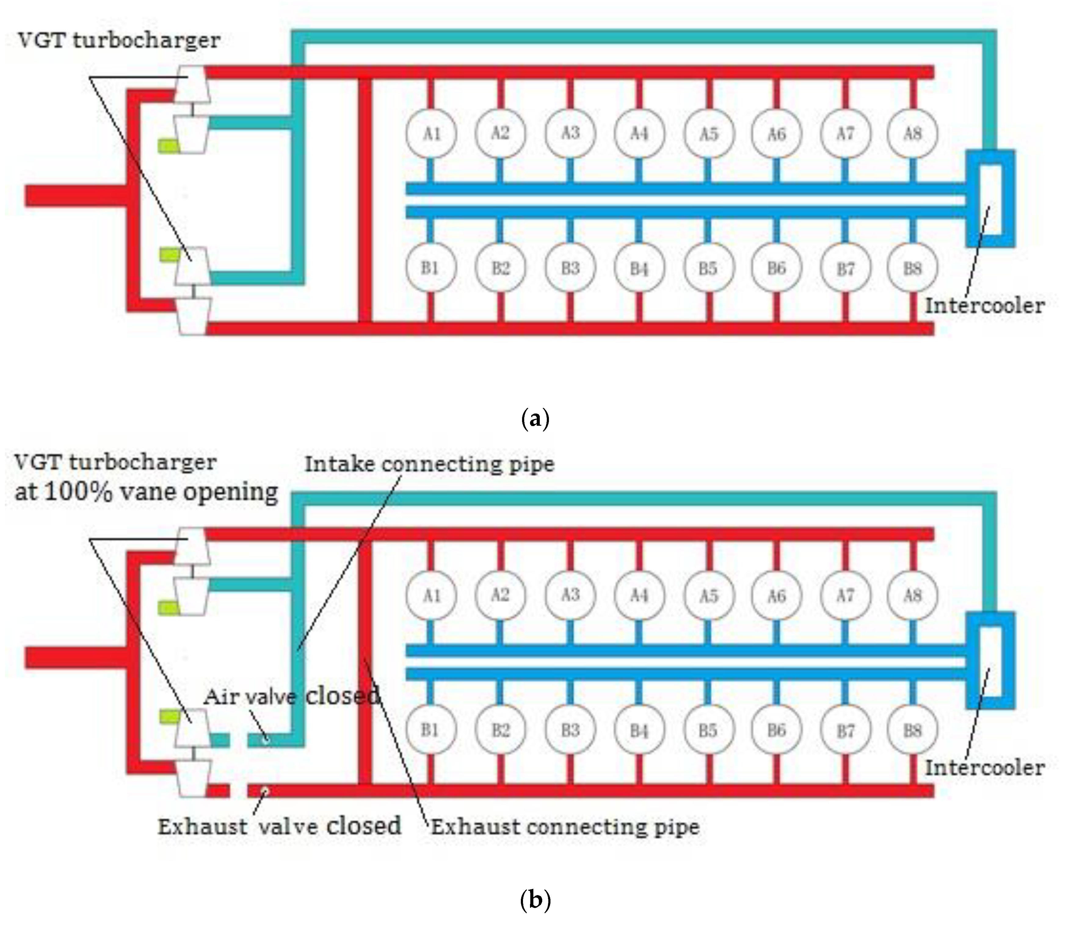
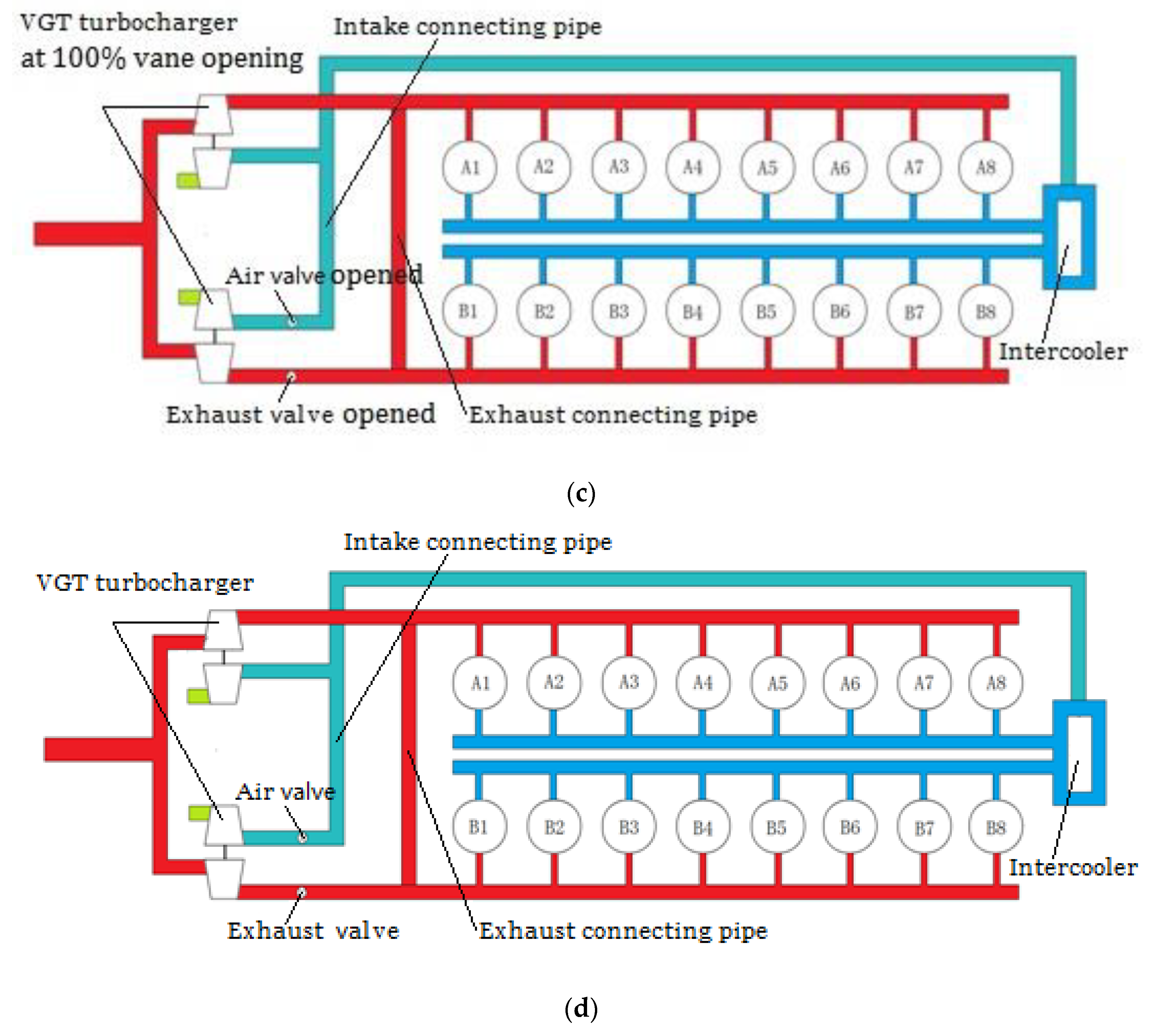
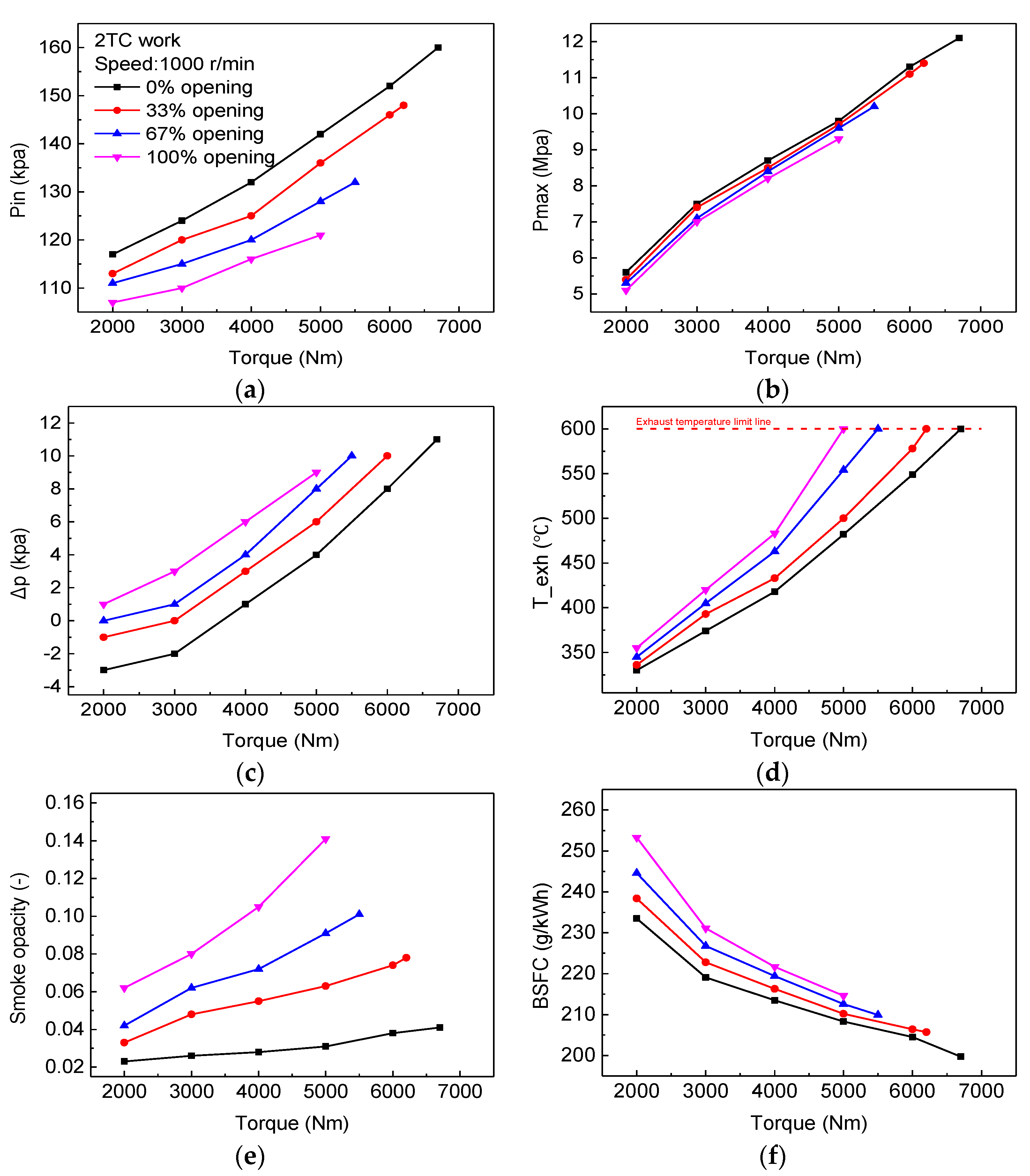
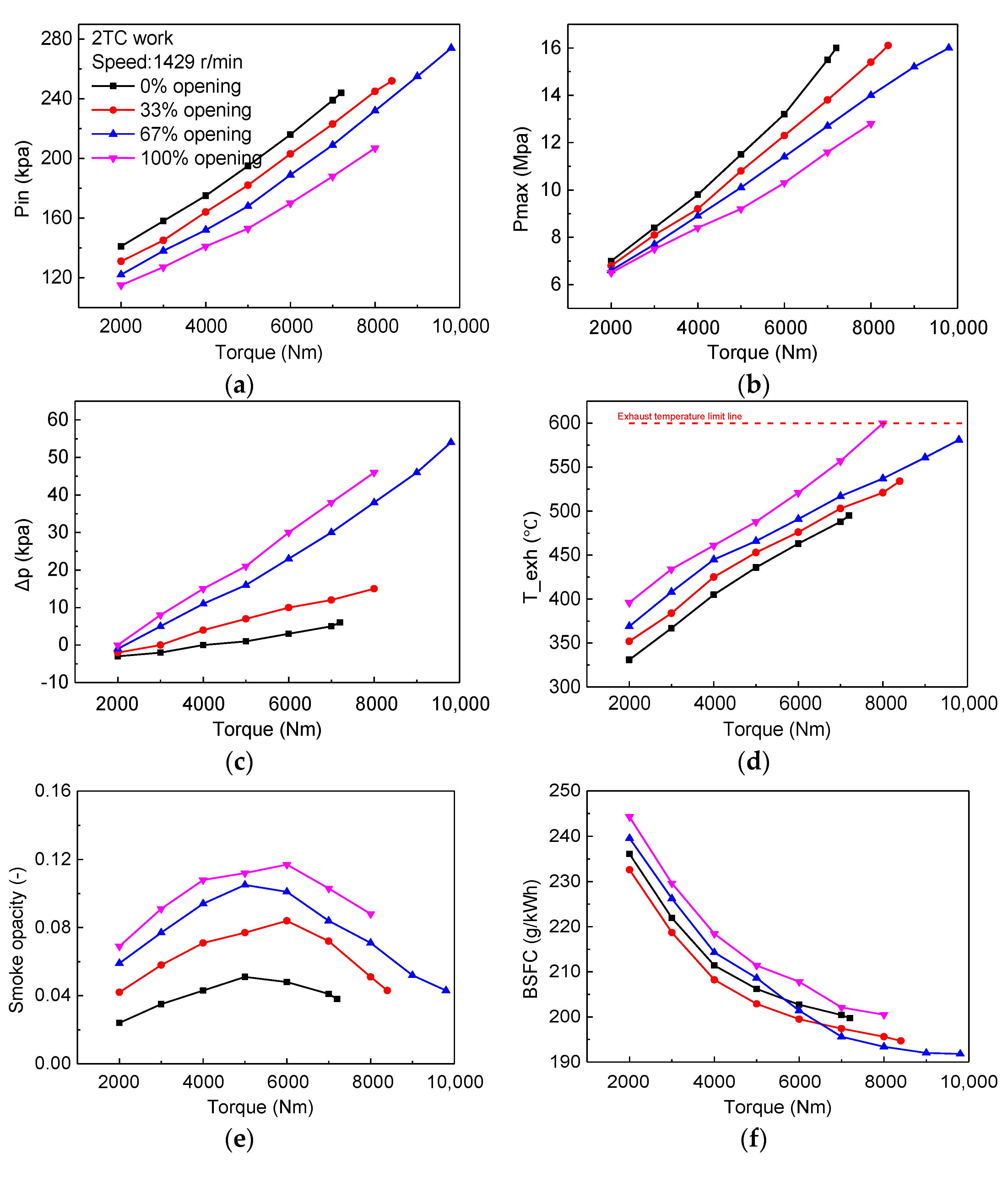
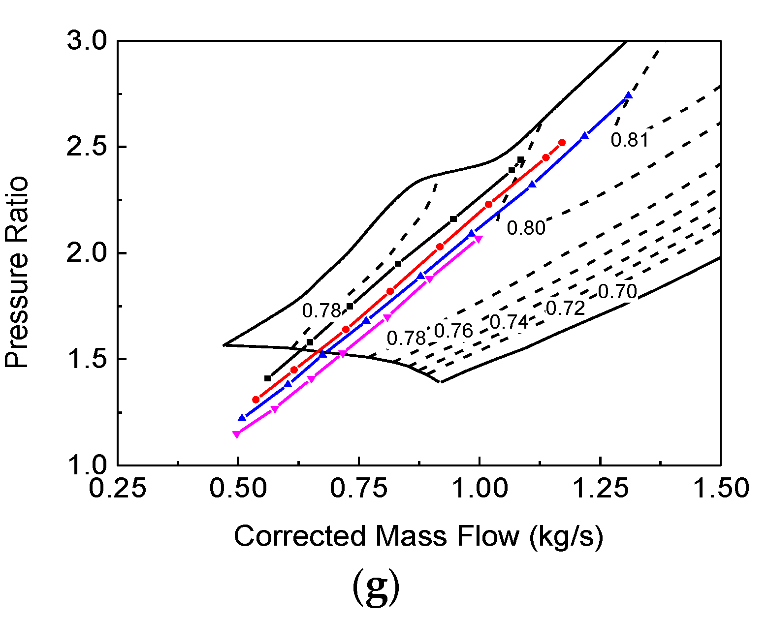
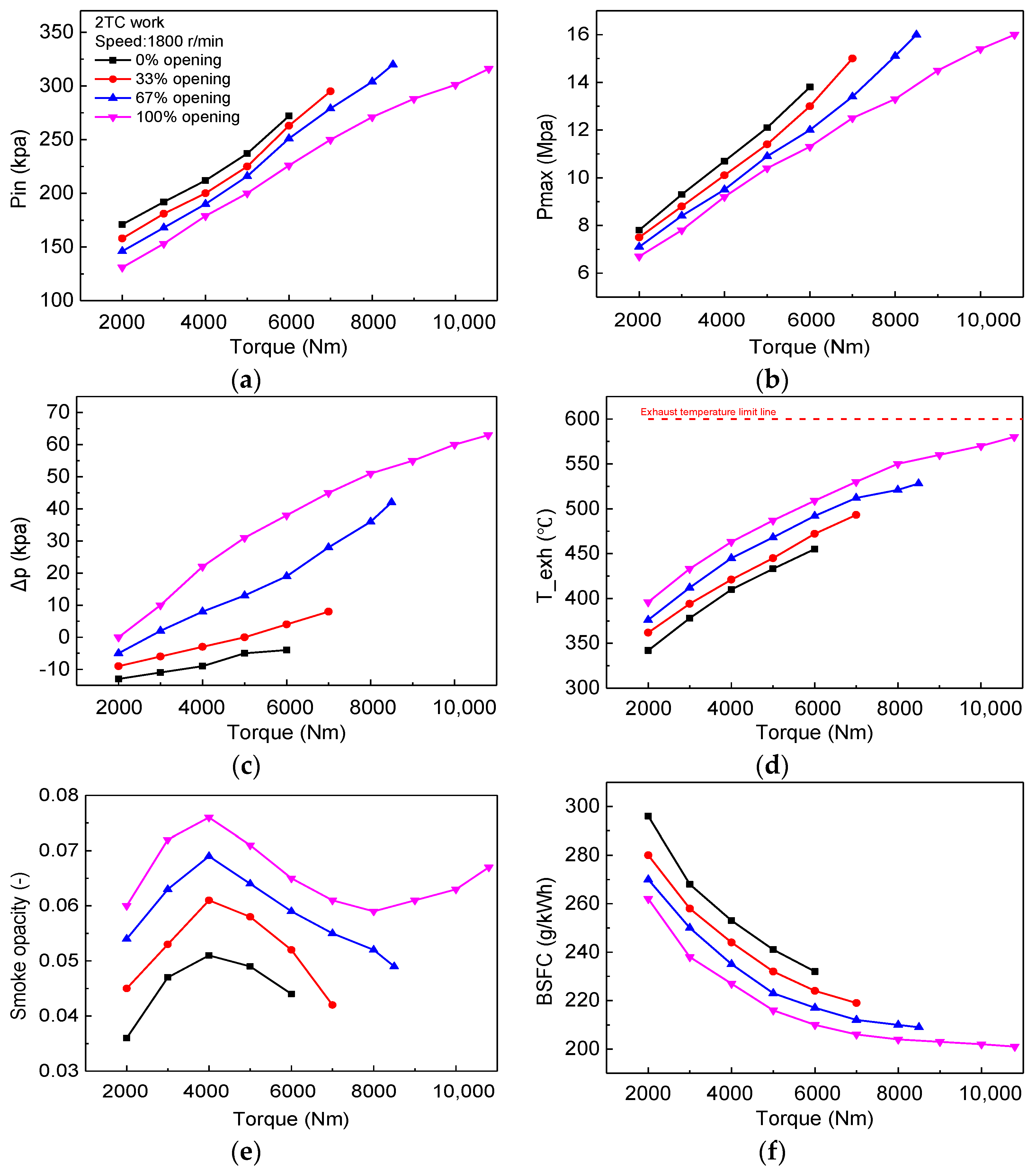
3.1. The Adjustment Characteristics of the VGT-2TC

The VGT vane opening has a vital impact on the performance of the engine. To understand it clearly, the impact on the performance with different VGT vane openings at 1000 rpm (representing low speed), 1429 rpm (representing medium speed), and 1800 rpm (representing high speed) are shown in Figure 2, Figure 3 and Figure 4.
It can be seen that the trends of some of the parameters, such as the intake pressure (pin) (Figure 2a, Figure 3a, and Figure 4a), the maximum combustion pressure (Pmax) (Figure 2b, Figure 3b, and Figure 4b), the exhaust temperature (Texh) (Figure 2d, Figure 3d, and Figure 4d) and the smoke opacity (Figure 2e, Figure 3e, and Figure 4e), were consistent at the different speeds. For the smoke opacity, it has a complex trend with the increasing speed. The generation of soot is mainly due to the small local air-fuel ratio caused by uneven fuel mixing. At 1000 r/min, the smoke opacity has a linear trend with the increase of the load, because the incomplete combustion leads to soot increasing in lower speeds and the intake pressure. At 1429 r/min and 1800, the soot first increases and then decreases, which is different at 1000 r/min. The air is increased significantly with increase of speed, when the load reaches 5000–6000 Nm, a sufficient intake of air mixes with the fuel completely, which improves the combustion process, so the soot starts to drop. It is noted that the soot increases again when load exceeds 8000 Nm in the 100% vane opening at 1800 r/min, because it has a high load and needs to inject a lot of fuel, leading to the uneven mixing of air and fuel.
As the VGT vane opening decreases at the same speed and torque, the intake pressure and the maximum pressure increase, and the maximum exhaust temperature decreases. The reason is because the smaller vane opening leads to a higher turbocharger speed and a higher intake pressure, more fresh air enters the cylinder and the maximum combustion pressure increases, as reported in Ref. [19]. The exhaust temperature is closely related to the combustion duration. More fresh air can shorten the duration of the combustion and reduce the proportion of afterburning, so the exhaust temperature decreases in the small vane opening. Soot can be produced because there is less oxygen and as a result, the higher intake pressure can reduce the soot emissions by decreasing the VGT vane opening, as reported in Ref. [22].
The Δp represents the difference between the intake and exhaust pressures. When the Δp is greater than 0, it has a positive effect on the diesel engine (pumping work), which is conducive to scavenging the air with a pressure difference. While the Δp is less than 0, it has a negative influence (pumping loss), which leads to more residual exhaust in the cylinder, as reported in Ref. [23]. This can be observed in Figure 2c, Figure 3c, and Figure 4c. the Δp increases as the VGT vane opening increases. At a low speed (1000 r/min), the range of the Δp is between −3 and 10 kpa and the impact of the pumping work or pumping loss on the diesel engines is limited. While at medium and high speeds, the Δp is from −10 to 60 kpa, which is much larger than at the low speeds and has a greater impact on the BSFC.
Figure 2g, Figure 3g, and Figure 4g show the variations on the compressor map with the different VGT vane openings. In the same operating conditions, when the VGT vane opening is small, the position of the operating point is relatively located in the upper right side, indicating a higher intake pressure and much more airflow, as reported in Ref. [19]. At 1000 r/min, all of the operating points are located below the compressor map. While at 1429 r/min and 1800 r/min, the variations are located in large flow and high-efficiency areas. It is worth noting that some positions of a 0% vane opening at 1429 r/min (Figure 3g) are close to the surge boundary, which is harmful to the compressor.
The brake specific fuel consumption (BSFC) is one of the most important parameters for diesel engines, and its variation is complicated compared with other parameters. It could be seen that the best vane opening of the lowest BSFC corresponding to 1000 r/min (Figure 2f) and 1800 r/min (Figure 3f) is at 0% and 100%, respectively, while it moved from a 33% to 67% vane opening at 6500 Nm at 1429 r/min (Figure 4f). The cause of this phenomenon can be found by analyzing the combustion process and pumping work, which is closely correlative with the pin and Δp, respectively, as reported in Ref. [21]. First, at 1000 r/min, the 0% vane opening had the largest intake pressure, resulting in a good combustion process. The Δp was -3 and 10 kpa at the 0% and 100% vane openings, respectively, they all had little and limited effect on the BSFC because of the small values. So the combustion process (equal to the Pin) had a more important influence on the BSFC than the pump work (equal to the Δp) at low speeds. Second, at 1800 r/min, it had the lowest Pin and the highest Δp at the 100% vane opening due to the high engine speed. The pump work (equal to the Δp) had a more important influence on the BSFC than the combustion process (equal to the Pin), leading to the lowest BSFC at the 100% vane opening. Third, at 1429 r/min, the proper vane opening corresponding with the lowest BSFC was not a constant, indicating that it was a transitional state and was used to balance the combustion process and the pump work. With the increase of speed, the pumping work gradually plays a more dominant role on the BSFC. As a result, it can be seen from Figure 2f and Figure 3f that the lowest BSFC at 1000 r/min and 1429 r/min has been reduced by 11.6 g/kWh and 9.0 g/kWh on average, respectively, compared with the baseline.
It also can be found in Figure 2, Figure 3 and Figure 4 that the maximum torque increased with a small vane opening at 1000 r/min and 1429 r/min compared with the baseline. The exhaust temperature is the major factor that limits the torque at low speeds, while the small vane opening received a higher Pin and a lower Texh, therefore the maximum torque increased. In contrast with the baseline, the maximum torque at 1000 rpm and 1429 rpm had been increased by 1700 Nm (34%) and 1800 Nm (22.5%), respectively. At 1000 r/min, the maximum torque is still restricted by the exhaust temperature at the 0% vane opening (Figure 2d), indicating that the VGT turbochargers cannot provide enough fresh air. At 1429 r/min, the limiting factors are the maximum combustion pressure in the 0% and 33% vane openings (Figure 3d), indicating that the VGT turbochargers can provide enough air.
From the above analysis, it can be concluded as follows: First, as the VGT vane opening decreases, the intake pressure and combustion pressure increase, the exhaust temperature and the smoke opacity decrease. Second, at 1000 r/min, the variation on the compressor map with all vane openings is below the map and the limiting factor of the torque is still the exhaust temperature, indicating that the compressor cannot work well and provide enough air at low speeds. Third, the variation of the BSFC was complicated, which was affected by the combustion process (Pin) at low speeds, while converting to the pump work (Δp) at high speeds, and balancing the combustion process and pump work at medium speeds. Fourth, the torque was increased at 1000 r/min and 1429 r/min, due to the higher intake pressure and the lower exhaust temperature.

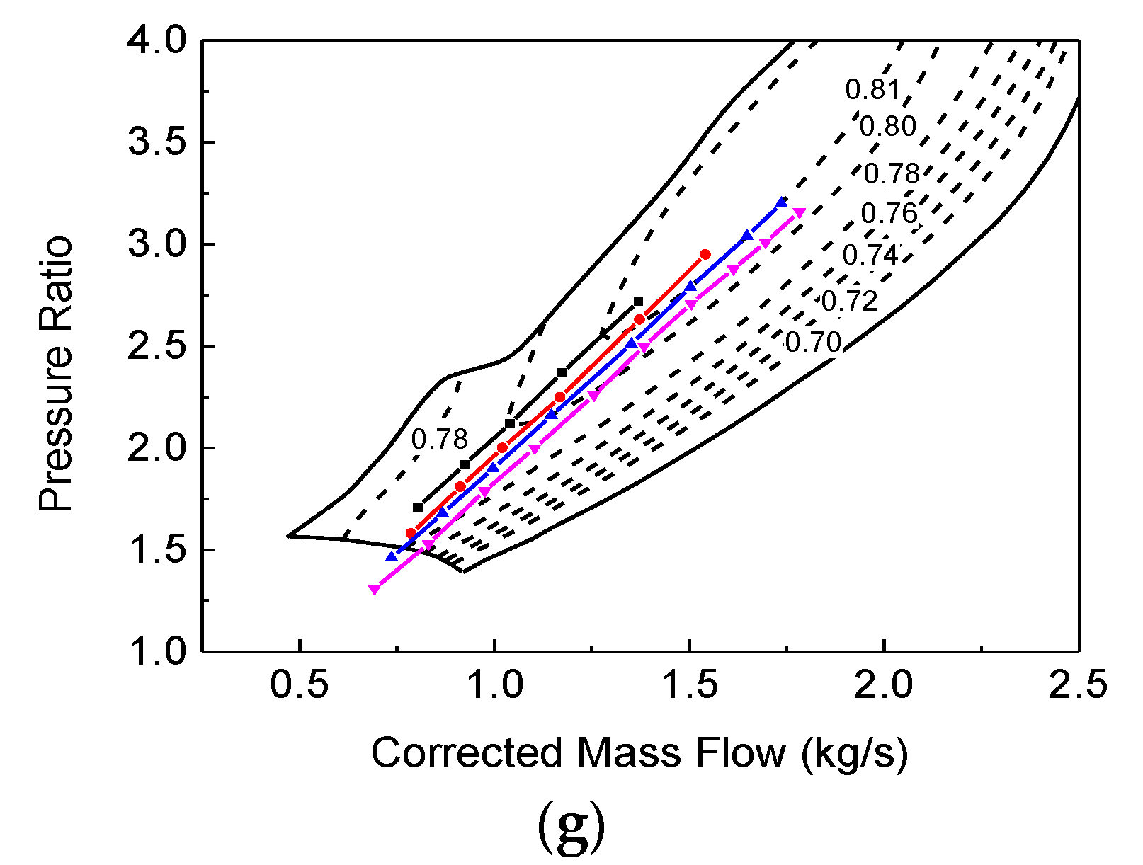
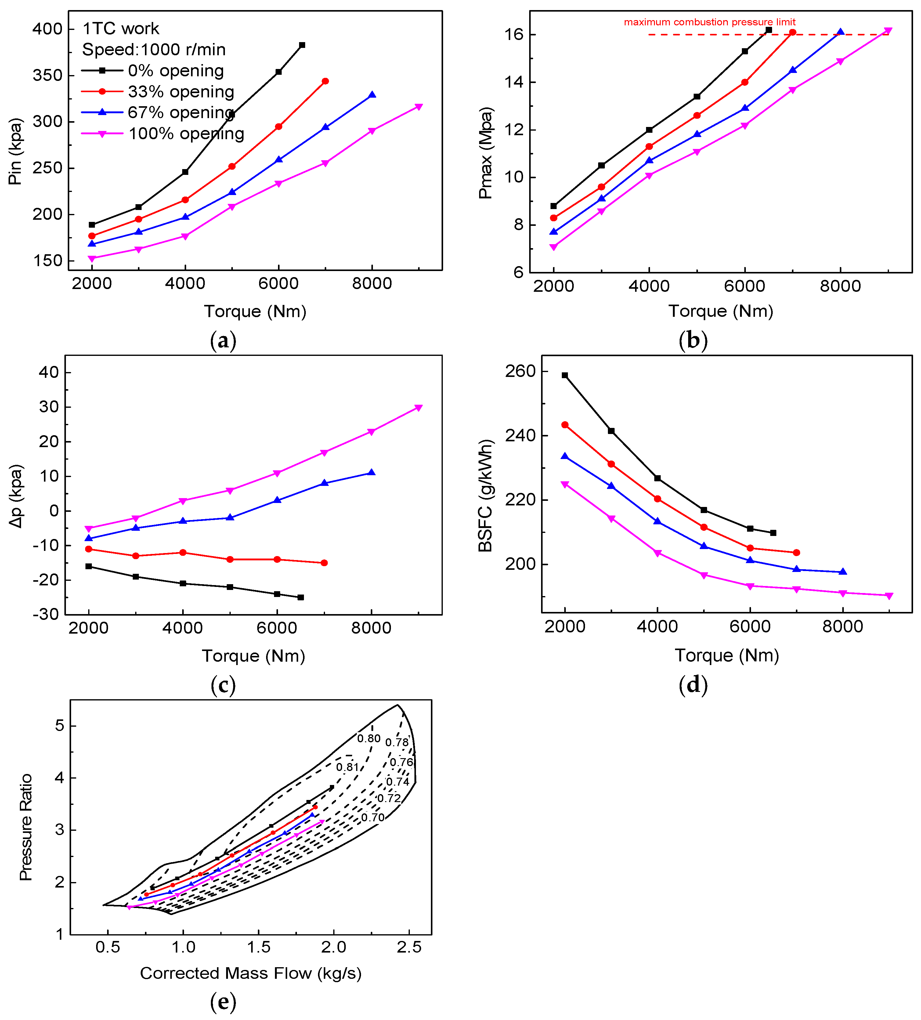
3.2. The Adjustment Characteristics of the VGT-1TC

For the VGT-1TC, the variation trend of some parameters, such as the smoke opacity and exhaust temperature, are consistent with the VGT-2TC, so we do not repeat them here, we will just show the different aspects. It can be intuitively observed that the pin (Figure 5a, Figure 6a, and Figure 7a) and Pmax (Figure 5b, Figure 6b, and Figure 7b) are much higher than the 2TC in the same operating conditions. The reason for that is because all of the exhaust flows into only one turbocharger instead of dividing the exhaust into two turbochargers, which increases the turbocharger speed and the intake pressure, as reported in Ref. [25]. It is worth noting that the lowest BSFC (Figure 5d, Figure 6d, and Figure 7d) can be obtained in the 100% vane opening in all speeds, this is because the pumping loss (equal to the Δp) plays a more important role on the BSFC than the combustion process (equal to the Pin) with the VGT-1TC. It can also be found that the VGT-1TC has no ability to regulate because of the constant (100%) best vane openings for all speeds. As a result, the BSFC has been decreased by 20.1 g/kWh on average.
The variations of the compressor are very different in contrast with the VGT-2TC, as shown in Figure 5e, Figure 6e, and Figure 7e. At 1000 r/min, the operating points are in the center of the compressor map, indicating that the compressor worked in the high-efficiency area. At 1429 r/min, the variations are close to the choke line, which means the compressor efficiency had dropped down greatly and would choke. At 1800 r/min, the compressor worked at the choked area of the map, which showed that the compressor had a significant flow blockage, as reported in Ref. [26]. Therefore the feasible speed operating conditions are 1000~1429 r/min for the VGT-1TC.
It can be found that the maximum torque increased because of the higher intake pressure at 1000 r/min, and it is worth noticing that the limiting factor of the torque is the maximum combustion pressure, which indicated that the VGT-1TC provided much more air than the VGT-2TC. At 1429 r/min, the maximum torque decreased, because the turbocharger operated close to the choke line and could not provide enough airflow for only one turbocharger, as reported in Ref. [27]. Compared with the baseline, the maximum torque at 1000 rpm and 1429 rpm in the 1TC with the 100% vane opening had been increased by 4000 Nm (80%) and decreased by −400 Nm (−5%), respectively.
To sum up, we conclude as follows for the VGT-1TC: First, the best vane opening corresponding to the lowest BSFC is 100%, indicating that the VGT loses the ability of adjustment in the VGT-1TC. Second, the working conditions are between 1000~1429 r/min and when the speed is greater than 1429 r/min, the compressor works on the choked area. Third, compared with the baseline, the torque at 1000 rpm and 1429 rpm has been increased by 4000 Nm (80%) and decreased by −400 Nm (−5%), respectively.

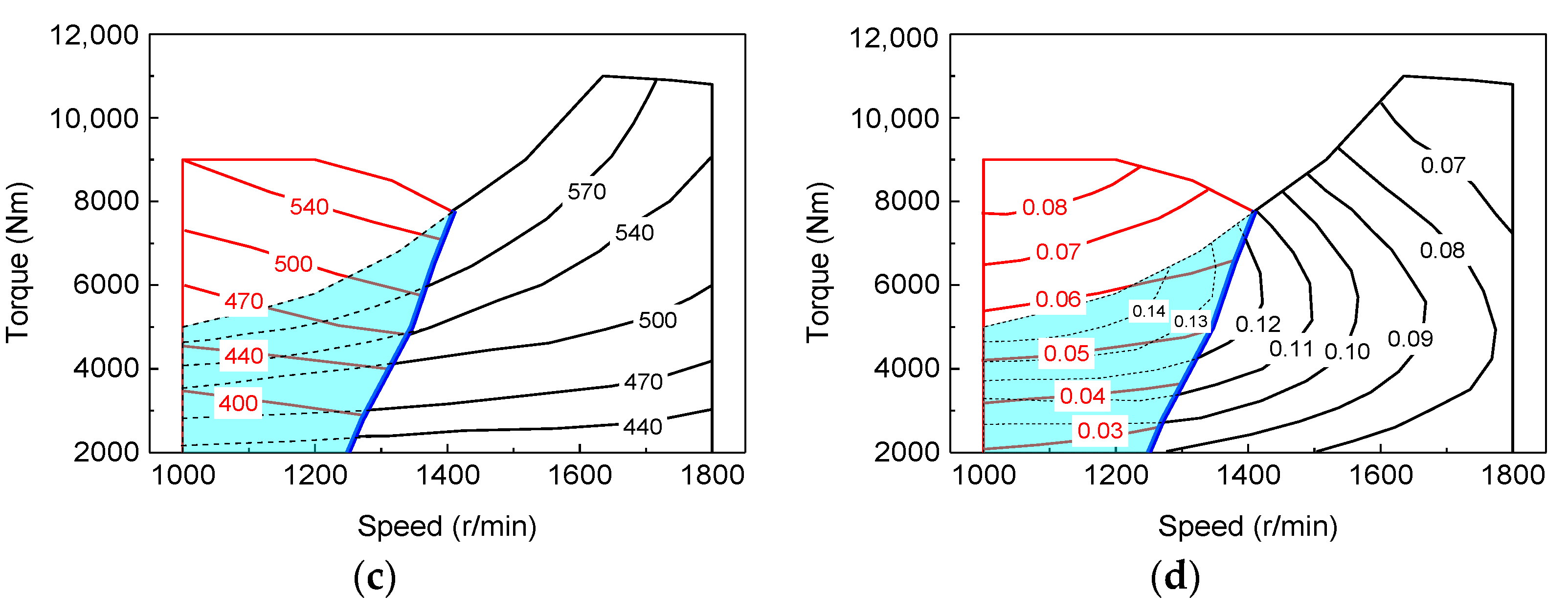
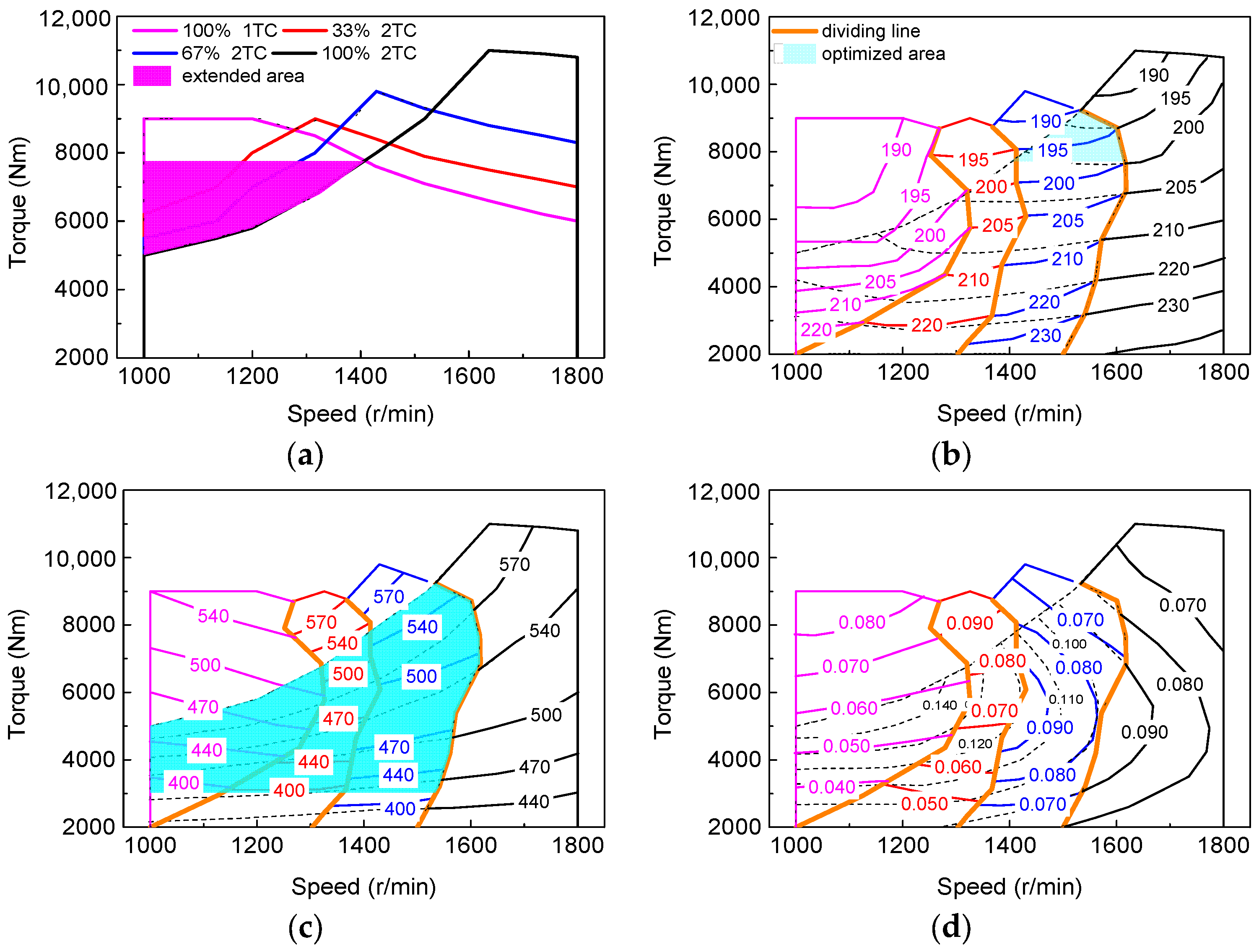
3.3. Characteristics of the VGT, STC and the Compound VGT-STC

The VGT system contains four operating states with the 2TC, namely at a 0% opening, 33% opening, 67% opening, and a 100% opening. The engine operating range expands at low and medium speeds compared with the baseline, as shown in Figure 8a. As the speed increases, the expanded area increases steadily due to the increase of intake pressure, and the operating range is expanded by 25.0% between 1000–1500 r/min. The dividing line between the different vane openings is calculated according to the lower BSFC, as shown in Figure 8b. The optimized area almost occupies 70% of the original range and the lower the speed, the higher the improvement of the BSFC. The exhaust temperature (Figure 8c) and the smoke opacity (Figure 8d) also decreased greatly within the optimized area. From a global perspective, the smoke opacity, BSFC, and the exhaust temperature are significantly reduced with an average drop of 0.053, 7.2 g/kWh, and 60 °C in the optimized areas, respectively.
The STC system switches between the 2TC and 1TC by controlling the opening and closing of the valve, so it has only two operating states. It can be seen from Figure 9a that at 1000~1200rpm, the maximum torque is maintained at around 9000Nm. While the speed exceeds 1200 rpm, the torque has an obvious downward trend, therefore the performance of the STC at the medium speed has significantly decreased. This is because, in low speeds, diesel engines require relatively little air which one turbocharger can provide, however with the increase of speed, the air needed gradually increases, which one turbocharger cannot afford, therefore the performance begins to deteriorate. Finally, the torque operating range is increased by 44.2% at 1000~1400 r/min, the smoke opacity (Figure 9d), BSFC (Figure 9b), and the exhaust temperature (Figure 9c) are significantly reduced with an average drop of 0.071,10.5 g/kWh, and 90 °C in the optimized area, respectively.
The compound VGT-STC system can provide eight operating states theoretically, but according to the principle of minimum fuel consumption, only four states are actually available, namely the 100%-1TC, 33%-2TC, 67%-2TC, and 100% 2TC. The VGT-STC combines the advantages of the VGT and the STC. At 1000–1200 rpm, the STC system can take much more fresh air to improve the engine performance than the 0% vane opening-2TC. When it exceeds 1200 r/min, the STC performance begins to decline and switches to the VGT system at this time. The overall performance maintains an upward trend. It can be found that the maximum torque can be stabilized at about 9000 Nm (83% rated torque at 1800 rpm) at 1000–1500 r/min (Figure 10a). As a result, the operating range is expanded by 35.4%, the smoke opacity (Figure 10d), the BSFC (Figure 10b), and the exhaust temperature (Figure 10c) are significantly reduced with an average drop of 0.057, 8.2 g/kWh, and 64 °C in the optimized area, respectively.
In a similar study, torque was expanded in a diesel engine with a two-stage turbocharger system by 8.6% at 700–1100 r/min, and the BSFC was reduced by 3 g/kWh at a high efficiency zone in Ref. [37]. Ref. [19] applied a newly designed VGT in a V-type diesel engine, the results showed an external speed characteristic mode, the maximum torques increased by 9%, the exhaust temperature decreased by 40 °C, and the BSFC was reduced by 10g/kW h. By applying the electric-booster and turbo-generator system (EBTG) in a 1.5L gasoline engine in Ref. [36], the maximum reduction of the BSFC was 2.6% in 80–100% load, while it increased by 4.0% under a 30% load. Based on the above analysis, the compound VGT-STC system has the better performance on improving the fuel economy and performance than the other booster systems.

4. Conclusions

This paper investigated the matching characteristics of a V-type diesel engine by using a compound VGT-STC boosting system. The compound VGT-STC turbocharger system bench was established. Based on the test, the impact of the VGT vane opening on the diesel performance was evaluated for the VGT-1TC and VGT-2TC, in the first instance. Then, the characteristics of the VGT and STC were studied and discussed. Finally, we obtained the control strategy of the compound VGT-STC system by taking advantage of the VGT and STC. The following conclusion can be drawn.
(1)
For the VGT-2TC, as the VGT vane opening decreases, the intake pressure and the maximum combustion pressure increase, the smoke opacity, the exhaust temperature, and the Δp decrease. In low speeds (1000 r/min), the limiting factor of the maximum torque is still the exhaust temperature, indicating that the VGT cannot provide enough fresh air into the cylinder. The BSFC are closely related to the pin and Δp, the pin has a greater influence on the BSFC than the Δp at low speeds, and it is the opposite at high speeds. The torque increases at low and medium speeds, due to the higher intake pressure and lower exhaust temperature;
(2)
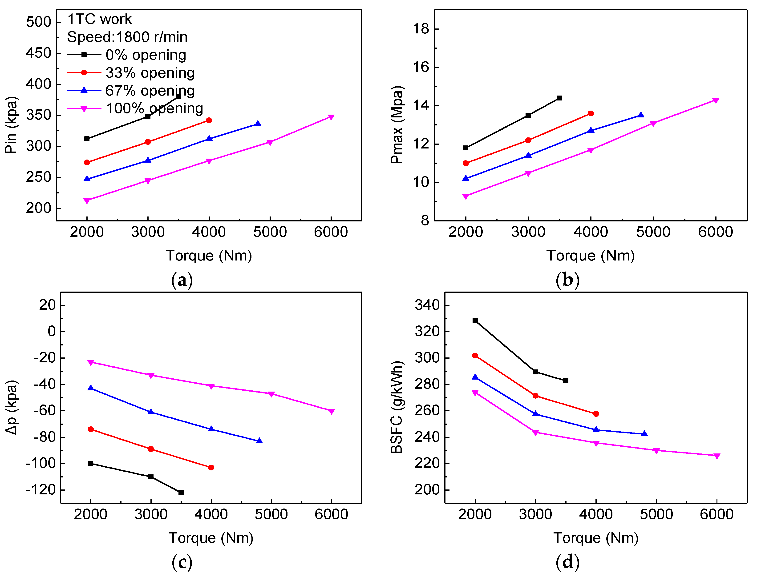
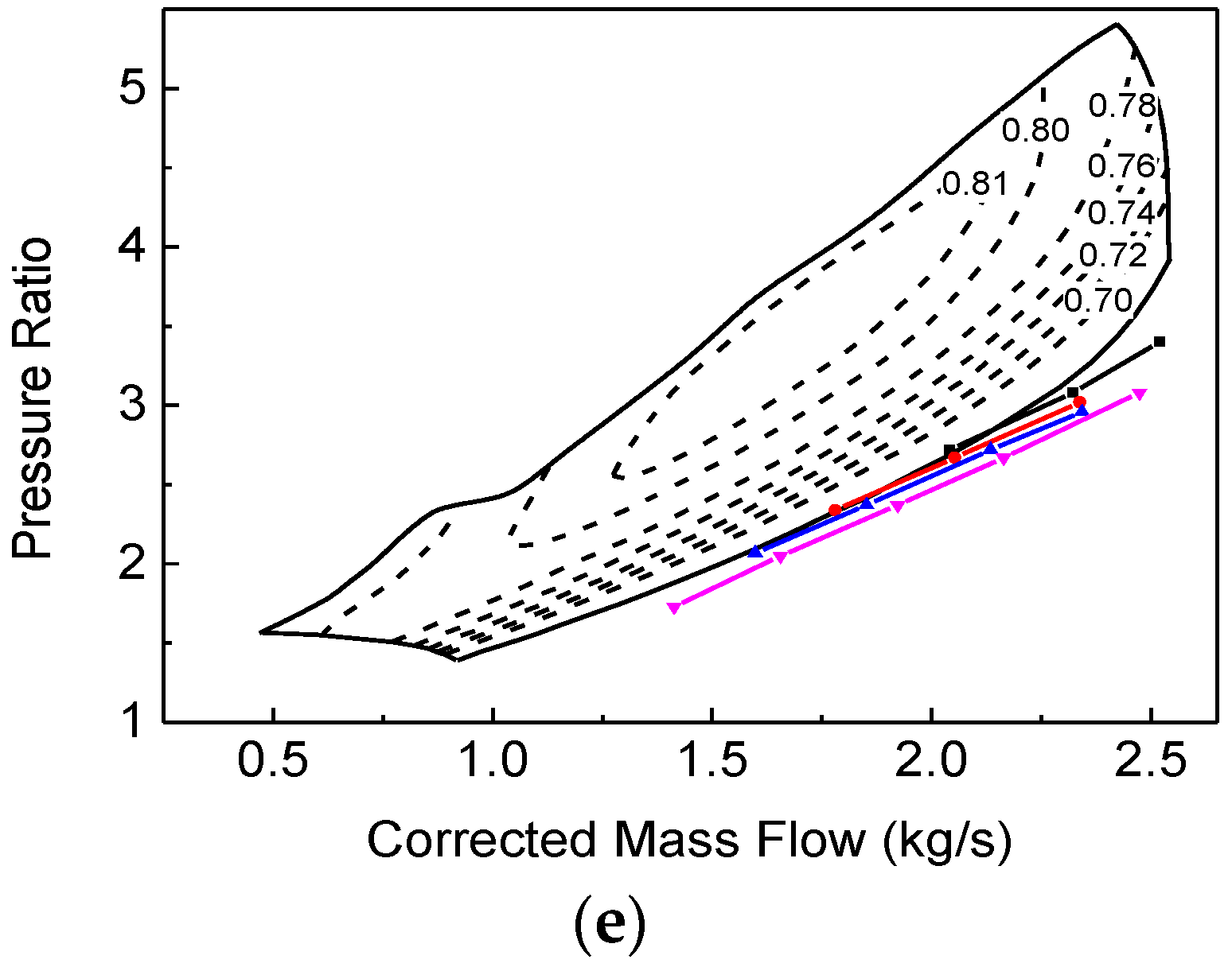
For the VGT-1TC, the best vane opening is a constant of 100%, indicating that the VGT loses the ability to adjust itself. The working conditions are between 1000~1429 r/min. The performance improves at low speeds and deteriorates at medium speeds;
(3)
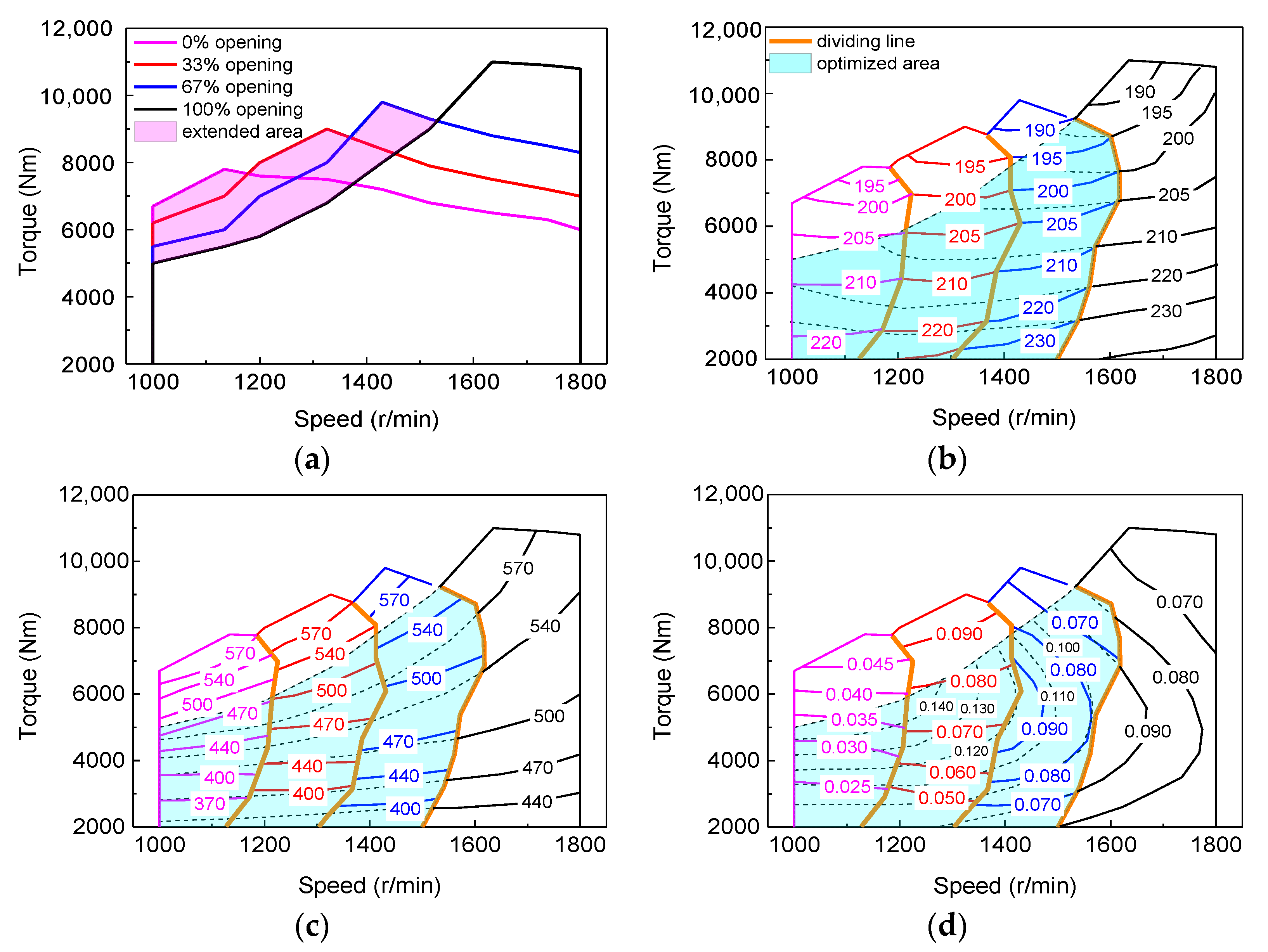
In the case of the VGT system, the maximum torque increases steadily in low and medium speeds, the torque operating range is increased by 25.0%. The smoke opacity, the BSFC, and the exhaust temperature are reduced with an average drop of 0.053, 7.2 g/kWh, and 60 °C, respectively;
(4)
In the case of the STC system, the maximum torque increases significantly in l000 rpm and starts to decrease at 1200 r/min. The operating range is increased by 44.2%. The smoke opacity, the BSFC, and the exhaust temperature are reduced by 0.071, 10.5 g/kWh, and 90 °C, respectively;
(5)
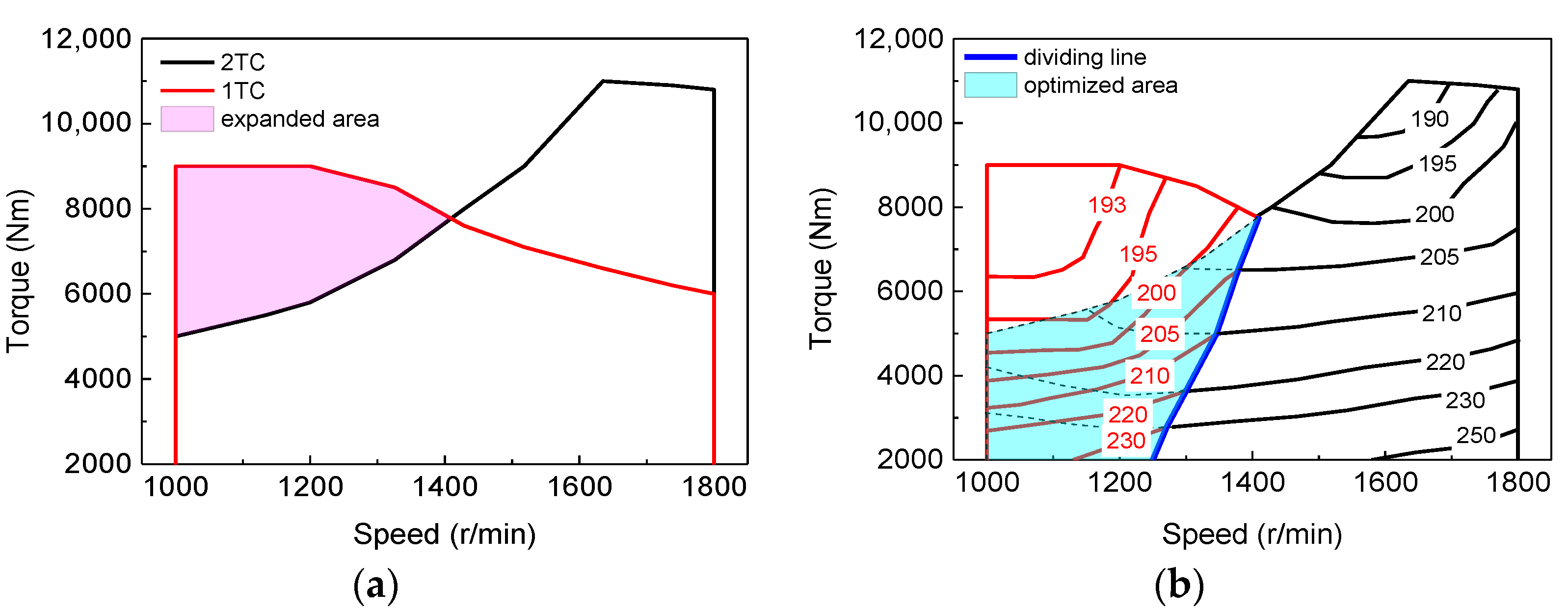
In the case of the compound VGT-STC system, the maximum torque can be stabilized at about 9000 Nm (90% rated torque at 1800 rpm) at 1000–1500 r/min. As a result, the operating range is increased by 35.4%. The smoke opacity, the BSFC, and the exhaust temperature are reduced by 0.057, 8.2 g/kWh, and 64 °C, respectively.
In this study, we discussed the matching characteristics of the compound VGT-STC system with a V-type diesel engine, and it had better performance compared with the original engine. We are now building a new single cylinder engine testbench with the same bore and stroke, which are equipped with an adjustable intake system and high-pressure common rail system, the couple effect of intake pressure, injection time, and injection pressure on combustion, performance and emission will be investigated in detail.

Author Contributions

M.S.: Investigation, Data analysis, Writing—original draft. H.W.: Study design, Methodology, Writing-review and editing. C.Y.: Literature search, Data curation, Writing-review and editing. Y.W.: Funding acquisition, Project Supervision, Writing—review and editing. X.N.: Funding acquisition, Data curation, Writing—review and editing. All authors have read and agreed to the published version of the manuscript.

Funding

This work is supported by the Natural Science Foundation of China (2019-JCJQ-146-00).

Institutional Review Board Statement

Not applicable.

Informed Consent Statement

Not applicable.

Data Availability Statement

Data available on request to corresponding author.

Acknowledgments

The authors would like to thank reviewers for their valuable comments on this research.

Conflicts of Interest

The authors declare that they have no known competing financial interest or personal relationships that could have appeared to influence the work reported in this paper.

References

  1. Rakopoulos, C.D.; Dimaratos, A.M.; Giakoumis, E.G.; Rakopoulos, D.C. Study of turbocharged diesel engine operation, pollutant emissions and combustion noise radiation during starting with bio-diesel or n-butanol diesel fuel blends. Appl. Energy 2011, 88, 3905–3916. [Google Scholar] [CrossRef]
  2. Turner, J.; Popplewell, A.; Marshall, D.; Johnson, T.; Barker, L.; King, J.; Martin, J.; Lewis, A.; Akehurst, S.; Brace, C.; et al. SuperGen on Ultraboost: Variable-Speed Centrifugal Supercharging as an Enabling Technology for Extreme Engine Downsizing. SAE Int. J. Engines 2015, 8, 1602–1615. [Google Scholar] [CrossRef]
  3. Zamboni, G.; Capobianco, M. Experimental study on the effects of HP and LP EGR in an automotive turbocharged diesel engine. Appl. Energy 2012, 94, 117–128. [Google Scholar] [CrossRef]
  4. Guan, W.; Pedrozo, V.B.; Zhao, H.; Ban, Z.; Lin, T. Miller cycle combined with exhaust gas recirculation and post–fuel injection for emis-sions and exhaust gas temperature control of a heavy-duty diesel engine. Int. J. Engine Res. 2019, 21, 1381–1397. [Google Scholar] [CrossRef]
  5. Schoedel, M.; Menze, M.; Seume, J.R. Experimentally Validated Extension of the Operating Range of an Electrically Driven Tur-bocharger for Fuel Cell Applications. Machines 2021, 9, 331. [Google Scholar] [CrossRef]
  6. Frigo, S.; Lutzemberger, G.; Martini, F.; Pasini, G. Performance evaluation of a medium size diesel vehicle equipped with different electric-turbo compound layouts. Iet Electr. Syst. Transp. 2018, 8, 71–79. [Google Scholar] [CrossRef]
  7. Bontempo, R.; Cardone, M.; Manna, M.; Vorraro, G. Steady and unsteady experimental analysis of a turbocharger for automotive applications. Energy Convers. Manag. 2015, 99, 72–80. [Google Scholar] [CrossRef]
  8. Unver, B.; Koyuncuoglu, Y.; Gokasan, M.; Bogosyan, S. Modeling and validation of turbocharged diesel engine airpath and combus-tion systems. Int. J. Automot. Technol. 2016, 17, 13–34. [Google Scholar] [CrossRef]
  9. Lou, D.; Lou, G.; Wang, B.; Fang, L.; Zhang, Y. Effect of LP-EGR on the Emission Characteristics of GDI Engine. Machines 2022, 10, 7. [Google Scholar] [CrossRef]
  10. Perceau, M.; Guibert, P.; Clenci, A.; Iorga-Simăn, V.; Niculae, M.; Guilain, S. Investigation of the Aerodynamic Performance of the Miller Cycle from Transparent Engine Experiments and CFD Simulations. Machines 2022, 10, 467. [Google Scholar] [CrossRef]
  11. Iqbal, M.Y.; Wang, T.; Li, G.; Li, S.; Hu, G.; Yang, T.; Gu, F.; Al-Nehari, M. Development and Validation of a Vibration-Based Virtual Sensor for Real-Time Monitoring NOx Emissions of a Diesel Engine. Machines 2022, 10, 594. [Google Scholar] [CrossRef]
  12. Chen, X.; Liu, L.; Du, J.; Liu, D.; Huang, L.; Li, X. Intelligent Optimization Based on a Virtual Marine Diesel Engine Using GA-ICSO Hybrid Algorithm. Machines 2022, 10, 227. [Google Scholar] [CrossRef]
  13. Laurén, M.; Goswami, G.; Tupitsina, A.; Jaiswal, S.; Lindh, T.; Sopanen, J. General-Purpose and Scalable Internal-Combustion Engine Model for Ener-gy-Efficiency Studies. Machines 2022, 10, 26. [Google Scholar] [CrossRef]
  14. Ghazikhani, M.; Davarpanah, M.; Shaegh, S.M. An experimental study on the effects of different opening ranges of waste-gate on the exhaust soot emission of a turbo-charged DI diesel engine. Energy Convers. Manag. 2008, 49, 2563–2569. [Google Scholar] [CrossRef]
  15. Li, H.; Shi, L.; Deng, K. Development of turbocharging system for diesel engines of power generation application at different altitudes. J.-Energy Inst. 2016, 89, 755–765. [Google Scholar] [CrossRef]
  16. Jin, J.; Pan, J.; Lu, Z.; Wu, Q.; Xu, L.; Fan, B.; Quaye, E.K. An Investigation On Performance of an Asymmetric Twin-Scroll Turbine with Small Scroll By-pass Wastegate for Heavy-Duty Diesel Engine. J. Eng. Gas Turbines Power 2020, 142, 061006. [Google Scholar] [CrossRef]
  17. Alaviyoun, S.; Ziabasharhagh, M.; Farajpoor, M. Experimental Investigation and Numerical Simulation of Gas Flow Through Wastegated Turbine of Gasoline Turbocharger. J. Appl. Fluid Mech. 2020, 13, 1835–1845. [Google Scholar]
  18. Feneley, A.J.; Pesiridis, A.; Andwari, A.M. Variable Geometry Turbocharger Technologies for Exhaust Energy Recovery and Boosting—A Review. Renew. Sustain. Energy Rev. 2017, 71, 959–975. [Google Scholar] [CrossRef]
  19. Samoilenko, D.; Marchenko, A.; Cho, H.M. Improvement of torque and power characteristics of V-type diesel engine applying new design of Variable geometry turbocharger (VGT). J. Mech. Sci. Technol. 2017, 31, 5021–5027. [Google Scholar] [CrossRef]
  20. Yang, M.; Gu, Y.; Deng, K.; Yang, Z.; Zhang, Y. Analysis on altitude adaptability of turbocharging systems for a heavy-duty diesel engine. Appl. Therm. Eng. 2017, 128, 1196–1207. [Google Scholar] [CrossRef]
  21. Serrano, J.R.; Piqueras, P.; De la Morena, J.; Gómez-Vilanova, A.; Guilain, S. Methodological analysis of variable geometry turbine technology impact on the performance of highly downsized spark-ignition engines—ScienceDirect. Energy 2020, 215, 119122. [Google Scholar] [CrossRef]
  22. Liu, Z.; Dizqah, A.M.; Herreros, J.M.; Schaub, J.; Haas, O. Simultaneous Control of NOx, Soot and Fuel Economy of a Diesel Engine with Dual-loop EGR and VNT using Economic MPC (Accepted, Control Engineering Practice). Control Eng. Pract. 2020, 108, 104701. [Google Scholar] [CrossRef]
  23. Xu, Y.; Zhang, S.; Gong, J.; Li, X. The effects of variable geometry turbine opening on reactivity controlled compression igni-tion combustion. Environ. Prog. Sustain. Energy 2019, 38, 13059.1–13059.9. [Google Scholar] [CrossRef]
  24. Giakoumis, E.G.; Tziolas, V. Modeling a Variable-Geometry Turbocharged Diesel Engine under Steady-State and Transient Conditions. J. Energy Eng. 2018, 144, 04018017. [Google Scholar] [CrossRef]
  25. Borila, Y.G. A Sequential Turbocharging Method for Highly-Rated Truck Diesel Engine; SAE paper: 860074; SAE: Detroit, MI, USA, 1986. [Google Scholar]
  26. Borila, Y.G. Some aspects of performance optimization of the sequentially turbocharged highly-rated truck diesel engine with turbochargers of unequal size and a pulse converter. IMECHE 1986, 105, 251–260. [Google Scholar]
  27. Tashima, S.; Taqdokoro, T.; Okimoto, H.; Niwa, Y. Development of Sequential Twin Turbo System for Rotary Engine. SAE Trans. 1991, 900–909. [Google Scholar] [CrossRef]
  28. Liu, R.; Yang, C.; Zhang, Z.; Jiao, Y.; Zhou, G. Experimental Study on Thermal Balance of Regulated Two-Stage Turbocharged Diesel Engine at Variable Altitudes. J. Therm. Sci. 2019, 28, 682–694. [Google Scholar] [CrossRef]
  29. Zhang, Z.; Liu, R.; Zhou, G.; Yang, C.; Dong, S.; Jiao, Y.; Ma, J. Influence of varying altitudes on matching characteristics of the Twin-VGT system with a diesel engine and performance based on analysis of available exhaust energy. Proc. Inst. Mech. Eng. Part D J. Automob. Eng. 2019, 234, 1972–1985. [Google Scholar] [CrossRef]
  30. Singh, D.V.; Pedersen, E. A review of waste heat recovery technologies for maritime applications. Energy Convers. Manag. 2016, 111, 315–328. [Google Scholar] [CrossRef]
  31. Di Battista, D.; Mauriello, M.; Cipollone, R. Waste heat recovery of an ORC-based power unit in a turbocharged diesel engine propelling a light duty vehicle. Appl. Energy 2015, 152, 109–120. [Google Scholar] [CrossRef]
  32. Zhao, R.; Wen, D.; Li, W.; Zhuge, W.; Zhang, Y.; Yin, Y. Characteristic and regulation method of parallel turbocompound engine with steam injection for waste heat recovery. Energy 2020, 208, 118422. [Google Scholar] [CrossRef]
  33. Mamat, A.M.; Romagnoli, A.; Martinez-Botas, R.F. Characterisation of a low pressure turbine for turbocompounding applications in a heavily downsized mild-hybrid gasoline engine. Energy 2014, 64, 3–16. [Google Scholar] [CrossRef]
  34. Rose, A.T.J.M.; Akehurst, S.; Brace, C.J. Modelling the performance of a continuously variable supercharger drive system. Proc. Inst. Mech. Eng. Part D: J. Automob. Eng. 2011, 225, 1399–1414. [Google Scholar] [CrossRef]
  35. Hu, B.; Tang, H.; Akehurst, S.; De Freitas, A.; Burtt, D.; Shawe, J. Modelling the Performance of the Torotrak V-Charge Variable Drive Supercharger System on a 1.0L GTDI—Preliminary Simulation Results; SAE International: Warrendale, PA, USA, 2015; Volume 1. [Google Scholar] [CrossRef]
  36. Zi, D.; Zhang, L.; Chen, B.; Zhang, Q. Study of the electric-booster and turbo-generator system and its influence on a 1.5 L gasoline engine. Appl. Therm. Eng. 2019, 162, 114236. [Google Scholar] [CrossRef]
  37. Wu, B.; Han, Z.; Yu, X.; Zhang, S.; Nie, X.; Su, W. A method for matching two-stage turbocharger system and its influence on engine performance. J. Eng. Gas Turbines Power 2019, 141, 054502. [Google Scholar] [CrossRef]
Figure 1. Schematic of the VGT, STC-1TC, STC-2TC, and the compound VGT-STC systems. (a) VGT; (b) STC-1TC; (c) STC-2TC; (d) Compound VGT-STC.
Machines 10 00788 g001aMachines 10 00788 g001b
Figure 2. Variations of the main engine parameters at 1000 r/min with the 2TC. (a) intake pressure. (b) the maximum combustion pressure. (c) difference between the intake and exhaust pressures. (d) exhaust temperature. (e) smoke opacity. (f) the brake specific fuel consumption. (g) compressor map.
Machines 10 00788 g002aMachines 10 00788 g002b
Figure 3. Variations of the main engine parameters at 1429 r/min with the 2TC. (a) intake pressure. (b) the maximum combustion pressure. (c) difference between the intake and exhaust pressures. (d) exhaust temperature. (e) smoke opacity. (f) brake specific fuel consumption. (g) compressor.
Machines 10 00788 g003aMachines 10 00788 g003b
Figure 4. Variations of the main engine parameters at 1800 r/min with the 2TC. (a) intake pressure. (b) the maximum combustion pressure. (c) difference between the intake and exhaust pressures. (d) exhaust temperature. (e) smoke opacity. (f) brake specific fuel consumption. (g) compressor.
Machines 10 00788 g004aMachines 10 00788 g004b
Figure 5. Variations of the main engine parameters at 1000 r/min with the 1TC. (a) intake pressure. (b) the maximum combustion pressure. (c) difference between the intake and exhaust pressures. (d) brake specific fuel consumption. (e) compressor.
Machines 10 00788 g005
Figure 6. Variations of the main engine parameters at 1429 r/min with the 1TC. (a) intake pressure. (b) the maximum combustion pressure. (c) difference between the intake and exhaust pressures. (d) brake specific fuel consumption. (e) compressor.
Machines 10 00788 g006aMachines 10 00788 g006b
Figure 7. Variations of the main engine parameters at 1800 r/min with the 1TC. (a) intake pressure. (b) the maximum combustion pressure. (c) difference between the intake and exhaust pressures. (d) brake specific fuel consumption. (e) compressor.
Machines 10 00788 g007aMachines 10 00788 g007b
Figure 8. Matching characteristics of the VGT system. (a) extended area. (b) contour of the BSFC. (c) contour of the exhaust temperature. (d) contour of the smoke opacity.
Machines 10 00788 g008
Figure 9. Matching characteristics of the STC system. (a) extended area. (b) contour of the BSFC. (c) contour of the exhaust temperature. (d) contour of the smoke opacity.
Machines 10 00788 g009aMachines 10 00788 g009b
Figure 10. Matching characteristics of the compound VGT-STC system. (a) extended area. (b) contour of the BSFC. (c) contour of the exhaust temperature. (d) contour of the smoke opacity.
Machines 10 00788 g010
Table 1. Engine specifications.
ParameterValue
Rated Power2032 kW
Engine speed at rated power1800 r/min
Number of cylinders/engine type 16/V-type
Bore170 mm
Stroke195 mm
Displacement72 L
Boost systemTurbocharger with intercooler
Fuel deliveryDirect injection
Table 2. The control strategy of the VGT-STC system.
Turbocharging System TypeAir and Exhaust Valve ModeVGT Condition
VGTOpened (2TC)Regulated
STCOpened (2TC)/Closed (1TC)Fixed
VGT-STCOpened (2TC)/Closed (1TC)Regulated
Table 3. The uncertainties of the measuring instruments.
InstrumentMeasured QuantityUncertainty
Inductive pick-upEngine speed±5 r/min
Eddy current dynamometerEngine torque1%
Fuel mass flow meterFuel consumption0.5%
K-type thermocoupleTemperature1%
KistlerPressure0.5%
AVLSmoke opacity0.1%
Publisher’s Note: MDPI stays neutral with regard to jurisdictional claims in published maps and institutional affiliations.

