Article

The Design and Control of a Footplate-Based Gait Robo-Assisted System for Lower Limb Actuator

by
Seyed Mohammadali Rahmati
1 and
Alireza Karimi
2,*
1
School of Biological Sciences, Georgia Institute of Technology, Atlanta, GA 30332, USA
2
Department of Ophthalmology and Visual Sciences, University of Alabama at Birmingham, Birmingham, AL 35233, USA
*
Author to whom correspondence should be addressed.
Machines 2022, 10(7), 546; https://doi.org/10.3390/machines10070546
Submission received: 17 June 2022 / Revised: 3 July 2022 / Accepted: 4 July 2022 / Published: 6 July 2022
(This article belongs to the Special Issue Dynamic Analysis of Multibody Mechanical Systems)

Abstract

:
Stroke causes disability in the lower-limb symmetry gait pattern in affected patients. The patients would not be able to regain their usual walking ability independently unless they benefit from rehabilitation therapies. Footplate-based gait robo-assisted systems can help patients to conduct effective training/exercising while tracking their progress of recovery and can dramatically reduce the clinical labor costs of physiotherapy. In the sense of simulation and not the design of the mechanical structure, this study aims to perform a combination of dynamic and control simulation of a five degrees-of-freedom footplate-based gait robo-assisted system established according to the Stewart platform structure for use in lower limb rehabilitation of stroke patients. The effectiveness and performance of the proposed mechanism were assessed through a clinical gait pattern of a healthy male individual. The proposed robo-assisted system enables the simulation of the hip and knee flexion/extension as well as the ankle dorsiflexion/plantar flexion of stroke patients to reproduce their typical symmetry gait pattern. The results were interpreted as the dynamic movement characteristics of the right and left thigh, leg, and foot compared to the clinical gait pattern with a mean percentage error of 6.70% to show the effectiveness and accuracy of the developed robo-assisted system for lower limb actuation in the simulation process.

1. Introduction

The final objective of rehabilitation is to restore the patients to the highest physical, sensory, and mental capabilities [1] that were lost because of illness, injury, and disease [2]. Stroke and spinal cord injuries are ranked among the most severe neurological impairments. To regain the patient’s abilities, rehabilitation therapies are crucially important [3]. Stroke is a major cause of mortality and disabilities, resulting in motor deficits as well as lower and upper limb weakness [4]. The use of robots in gait training can enhance rehabilitation, but it needs to be done according to well-defined neuroscientific principles. The field of robot-mediated neuro-rehabilitation brings challenges to both bioengineering and clinical practice [5,6]. However, rehabilitation therapies for gait recovery need accurate imitation of the required pattern of the exercise with the help of trained physiotherapists and medical professionals [7,8]. Further, they have long training procedures, which would certainly be costly for the patients [9].
While robotic rehabilitation is more affordable, current robotic gait rehab devices have a high cost (of hardware) [10]. Many robotic instruments have been established to ease rehabilitation, such as those focusing on the knee, ankle, and even whole leg under various configurations [11,12]. These systems include treadmill gait trainers, footplate-based gait trainers, overground gait trainers, stationary gait trainers, and ankle rehabilitation systems [11,13]. These robo-assisted systems usually benefit from a body weight support system that controls the patient’s weight during gait training [14]. The lower limb rehabilitation robots have been developed in several types, while commonly categorized as exoskeleton and end-effector robots [15]. Exoskeleton robots are defined as treadmill-based and orthosis-based robots, while end-effector robots are footplates-based and platform-based types. Exoskeletons have been extensively studied for movement analysis of various joints in the body. These devices can involve a single degree of freedom (DOF), for example, flexion and extension of the forearm, or multiple DOF, e.g., hand movements. The complexity and physical capabilities of the exoskeleton depend on various factors, including the force/torque transmission medium, the range of motion, and the method of control [16]. Lokomat [17], BLEEX [18], and LOPES [19] are the exoskeleton robots, whereas Rutgers-Ankle [20] and Haptic-Walker [21] are the end-effector robots. In a footplate-based gait trainer robot, the patient’s feet are positioned on separate footplates, whose movements are controlled by a robotic system to simulate different gait patterns [20,22]. Such systems can assist the patients by the speed and weight adaption to enhance the rehabilitation process [23]. In both categories of the exoskeleton and end-effector robots, only 3 DOF is actuated for each leg in the sagittal plane [24]. This study attempts to combine both systems in which the rehabilitation robot mimics the angular, horizontal and vertical movements of the foot by actuating the top plate of the Stewart platform and planner angular movements of the leg and thigh by using actuators in the ankle and knee joints. Therefore, it is possible to provide a better gait pattern with the actuation of 5 DOF. The joint actuators here are not like exoskeletons, which drive their corresponding lower limbs, but rather, they drive the limbs above them.
Robot-assisted lower limb therapy includes the simulation of the joint or foot path, such as gait trajectories produced by non-impaired people [25]. The resulting movement may contribute to other technologies, e.g., functional electrical stimulation [26], or additional levels of control, such as the ability to assist as needed [27]. Mechanical support is often delivered to the patient using either an exoskeletal device [28] or an end-effector-based robot [29]. While exoskeleton-based systems may lessen the strain on therapists, studies suggest that patient engagement in therapy may also be reduced [30], which may indicate that the neurological pathways required for rehabilitation are not properly stimulated. In view of this issue, recent research has proposed new treadmill control schemes [31], as well as structurally innovative treadmills [32]. Nevertheless, in this work, we focus on end-effector systems.
This study aims to design and control a 5 DOF footplate-based gait robo-assisted system on the basis of the Stewart platform structure for use in lower limb rehabilitation of stroke patients. The effectiveness and performance of the proposed mechanism, which actuates 5 DOF instead of 3 for the gait rehabilitation robot, were assessed through a clinical gait pattern of a healthy male individual. The proposed robo-assisted system enables the simulation of the hip and knee flexion/extension and the ankle dorsiflexion/plantar flexion as well as the transitional movement of the foot for the stroke patients to reproduce their typical gait pattern. The transitional and angular movements are produced by a combination of the end-effector robot and gait exoskeleton. The developed robo-assisted system can train and monitor the patient’s gait-reproducing progress using a multibody programming code. Here, the results in regard to the performance of the robot in controlling the dynamic movement characteristics of the right and left thigh, leg, and foot were calculated and compared to our experimentally measured clinical gait pattern.

2. Materials and Methods

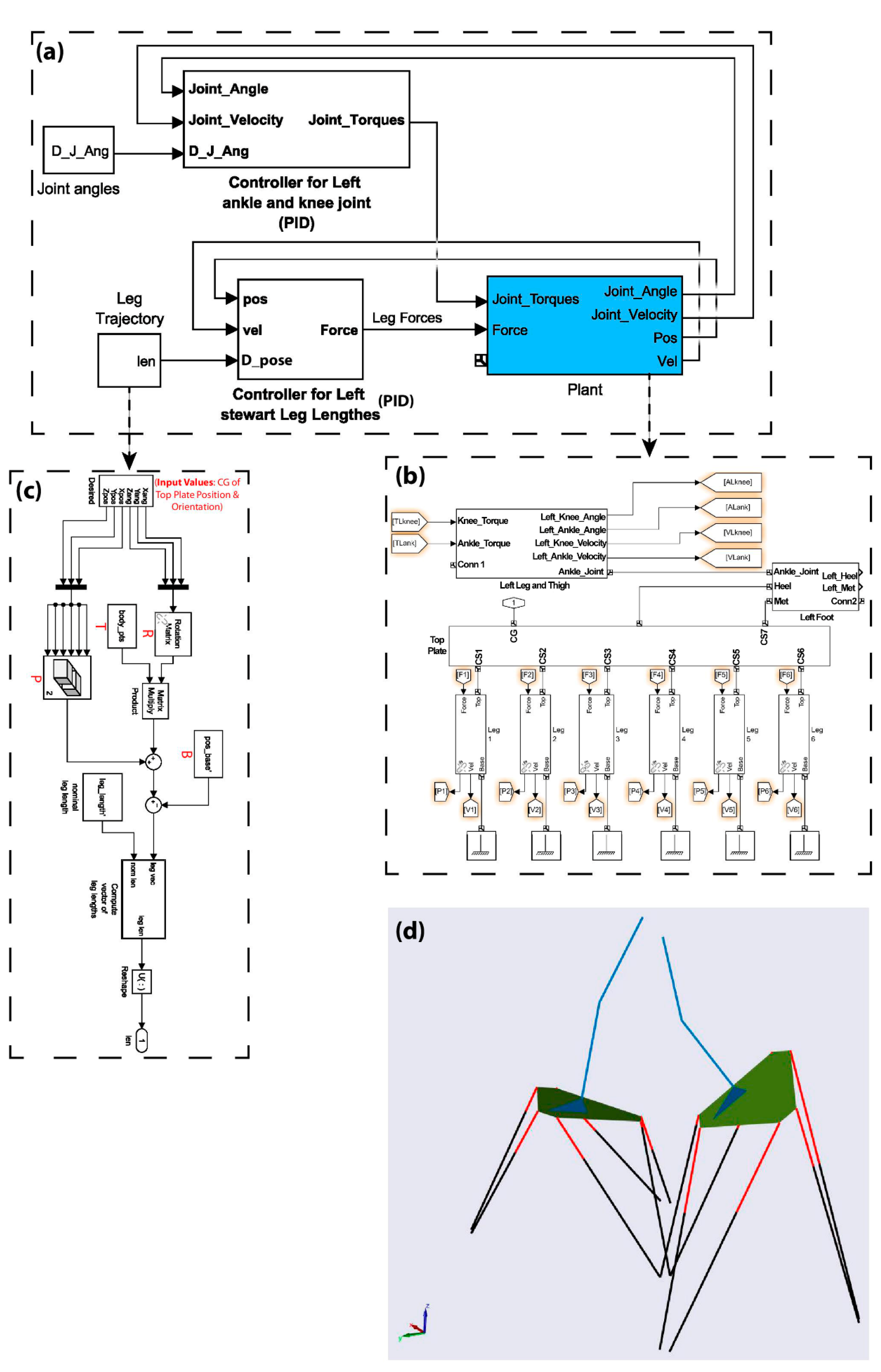
2.1. Mechanical Model of the System

The system dynamics were implemented by Matlab SimMechanics (MathWorks, Natick, MA, USA). Two Stewart platform robots, each with 6 DOF and a parallel manipulator-proportional integral derivative (PID) controller, were designed to simulate the heel horizontal/vertical trajectory and plantar/dorsiflexion angle. Each of them has six hydraulic actuated legs connected with universal and spherical joints to the base and moving platform (top plate), respectively. An exoskeleton connected to the moving platform was designed to follow the experimental trajectories of the right and left knee and hip angles. This exoskeleton is empowered by two actuators controlling the angles for each leg and thigh. The actuators are located on the ankle and knee joints. Since the angular and transitional movement of the foot is produced by the Stewart platform, the actuator on the ankle and knee joints drive the leg and thigh, respectively. Therefore, all joint positions can be computed in an open-loop kinematic chain. The dynamic performance of the exoskeleton is similar to a planner double inverted pendulum. The cables connected to a separate structure tolerate the body weight of the subject. The SimMechanics model of the left Stewart platform and exoskeleton is shown in Figure 1, which demonstrates the general form of applied blocks in the modeling of the system (a). The dynamical model of the system contains two controller blocks and one plant block. The controller blocks represent the PID controllers for the Stewart platform and actuators at the ankle and knee joints. The plant block demonstrates the mechanical model of the Stewart platform as well as the exoskeleton. A more detailed plant block is also provided (b). It includes six leg blocks connected to the base and moving platform, a foot block fixed to the moving platform with a weld connection, and the exoskeleton of the leg and thigh connected by hinge joints. Further, instead of using a control-based relationship between the spatial position of the top plate and forces produced by hydraulic legs, a more straightforward relationship can be presented via a relationship between the length and force of the hydraulic legs. In order to transfer the spatial status (positions and angles) of the top plate to the lengths of hydraulic legs, a rotation matrix has been used (c). A schematic view of the simulated Stewart platforms and exoskeletons is also provided (d).

2.2. Control Model of the System

Two controllers are needed to move the top platform and two-link exoskeleton from the initial position to a desired position and orientation. They will generate the required forces for each motor. The position and angle control of the top plate was determined based on the heel position and foot angle in the sagittal plane and can be reduced to the Stewart leg position control after path planning and inverse kinematic algorithms. A PID controller was developed and implemented here. A similar separate PID was developed to control the angles of ankle and knee joints for the exoskeleton. Control algorithms were designed in a Simulink environment. The optimization toolbox of Matlab was used to obtain the controller’s parameters (Kp, Ki, and Kd) for the PID controllers. By defining the controller parameters as optimization parameters and using sequential quadratic programming (SQP) as an optimization approach, the best possible PID parameters were obtained to minimize the difference between the desired trajectories and actual ones.
All robots were electromechanical devices composed of mechanical structures, actuators, and sensors. The control of the robot’s motion is possible if, and only if, the kinematic and dynamic equations of the system are known. For the controller design, at first, the kinematic solution needs to be computed. In the Stewart platform (Figure 1d), the coordinate systems corresponding to the center of gravity (COG) of the base and top are B = {X, Y, Z} and T = {x, y, z}, respectively. Base and top joint points can be labeled as Bi (i = 1, 2, …, 6) and Ti (i = 1, 2, …, 6), respectively.
In order to fulfill the moving platform to its desired position and orientation, the leg lengths should be found by inverse kinematics. Required leg vectors (Li) for the given position vector P and orientation matrix R were obtained by using the following equation [33,34,35,36].
L i = R X Y Z T i + P - B i i = 1 , 2 , , 6
A Simulink model was designed, and an *m-file was written to obtain an inverse kinematic solution by applying Equation (1). Therefore, the Ti and Bi position vectors can be computed based on robot structure. The model presented in Figure 1c uses the *m-file to get required variables and takes the desired position (x, y, z) and orientation (φ, θ, ψ) of the top platform as the input and provides the leg lengths as the output.

2.3. Implementation of Gait Intervention in the System

The gait pattern of a healthy male individual aged 29 years old, free of gait altering injuries, was recorded. The gait pattern is the representation of the walking cycle in terms of the hip and knee flexion/extension as well as the ankle dorsiflexion/plantar flexion angles at every instance of complete stride of both the right and left legs. Experimental data, including movement kinematics and ground reaction forces, were acquired by 44 reflective markers attached to the anatomical locations based on a six-camera VICON (Vicon Motion Systems Ltd., Oxford, UK) plug-in-gait marker placement protocol and one Kistler force plate, respectively, for two double support phases (DSP) and two single support phases (SSP) of five gait cycle trials with the mean velocity of 1.23 ± 0.10 m/s. The inverse kinematics method was applied to compute joint angles based on the recorded marker positions. The average kinematics values of these five trials were employed as the desired values in the SimMechanics model to estimate the actuator forces required to produce them. Since during gait training with the Stewart platforms and exoskeletons, a body weight support system was used to control the body weight of the patient according to the rate of disabilities. The force plate data was not applied to the system.

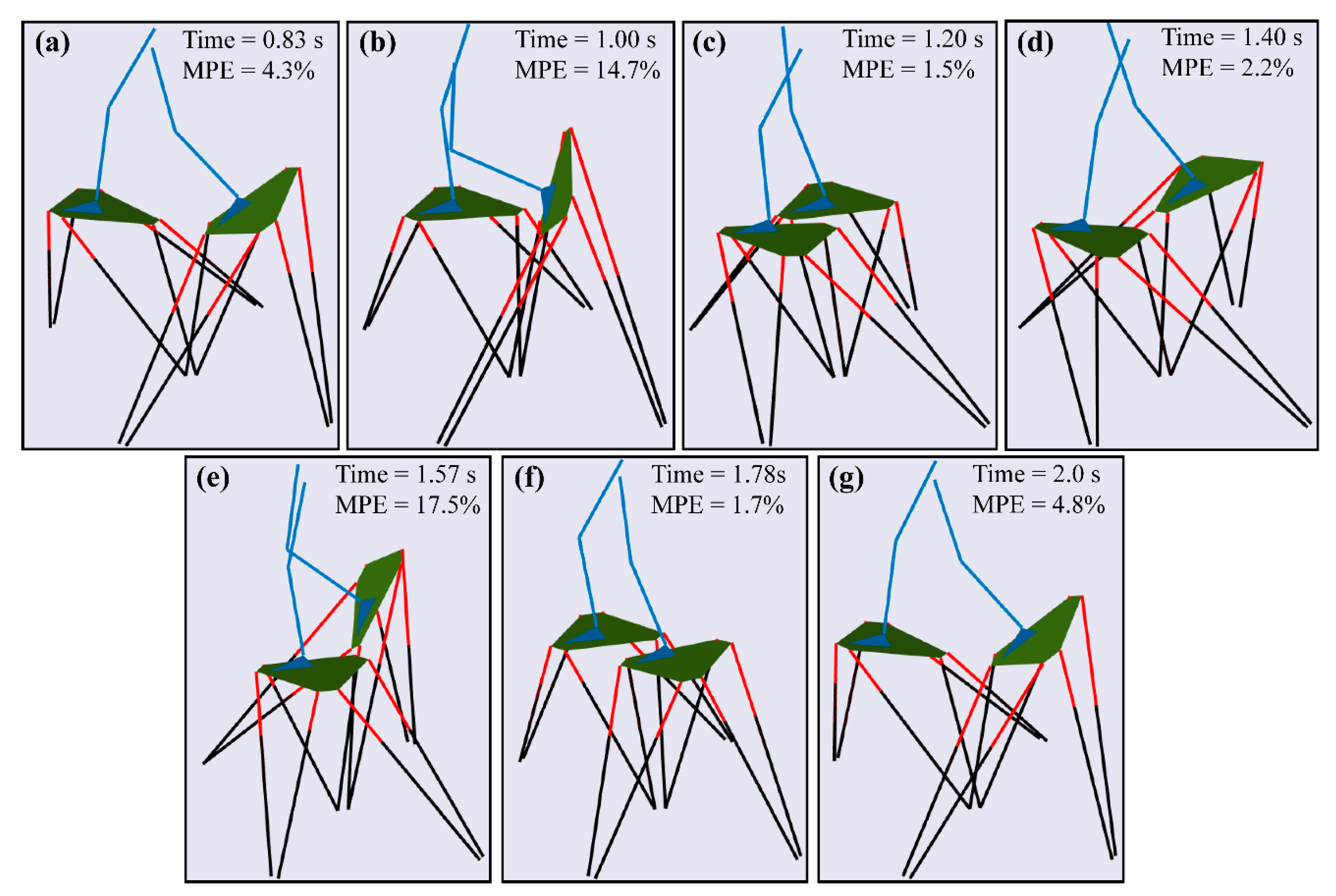
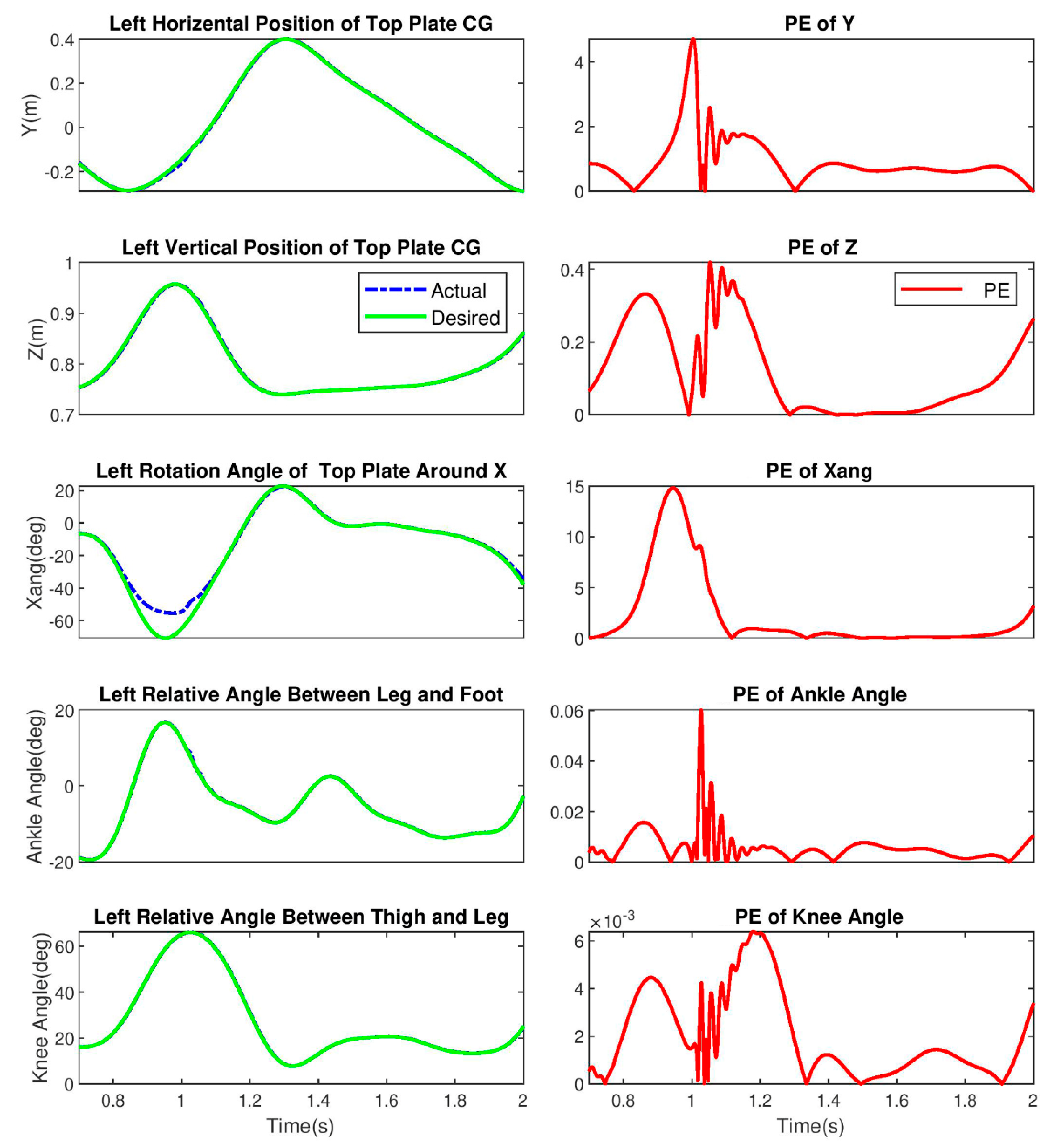
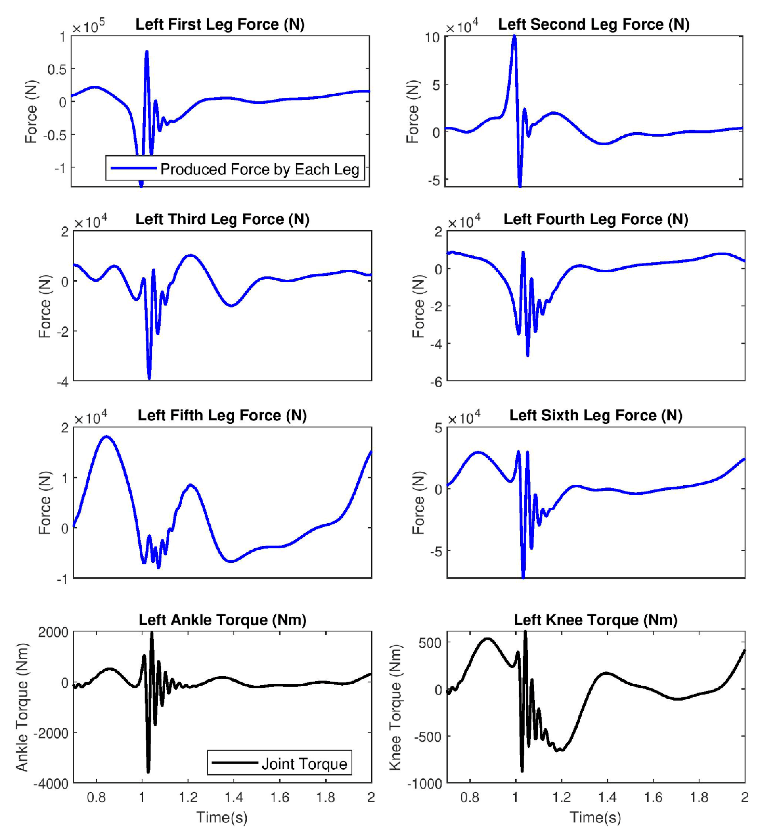
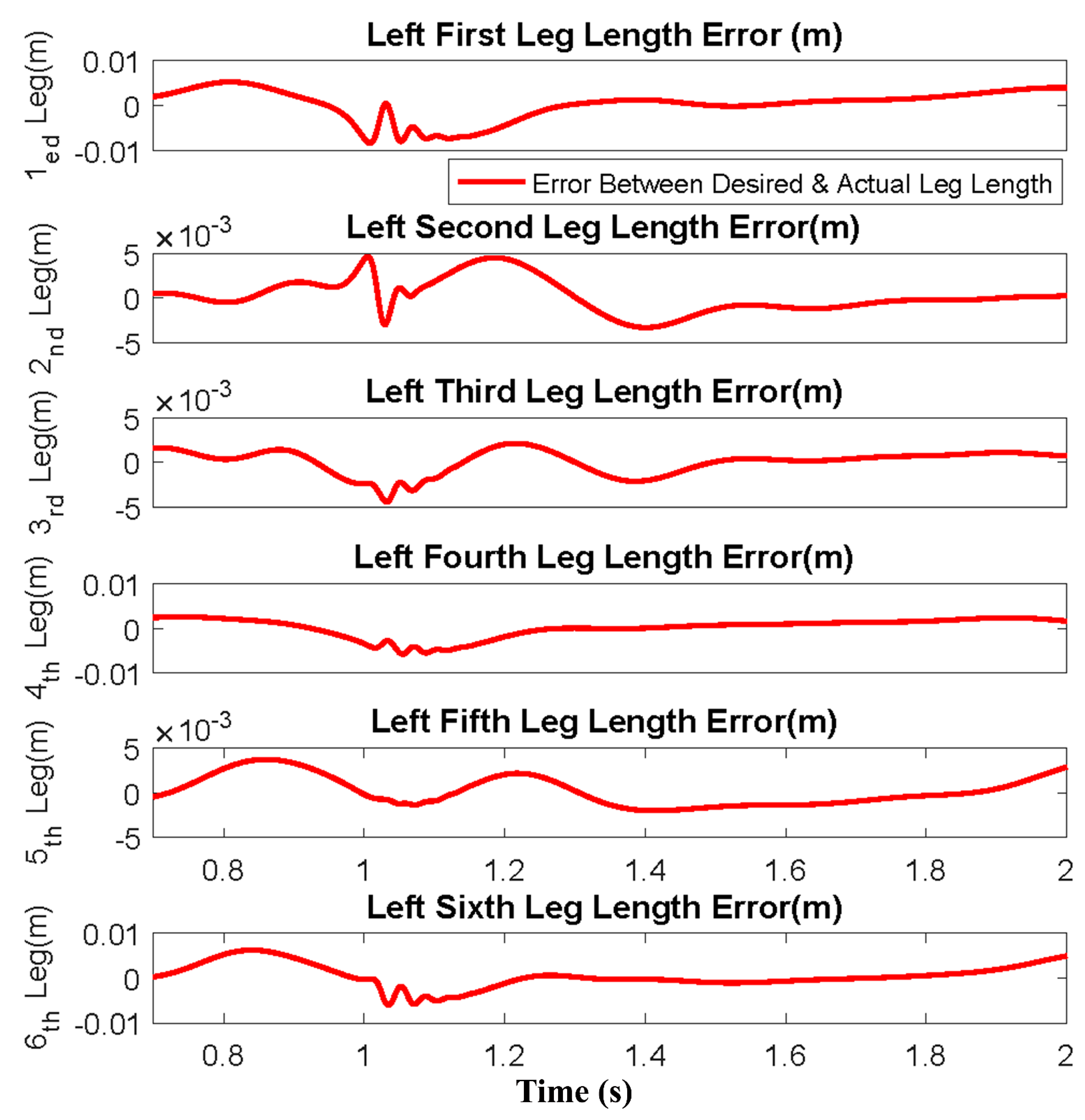
3. Results and Discussions

Rehabilitation is a major factor in care for stroke patients. Conventional rehabilitation therapies, including gait training, are not only very labor-intensive and require the help of physiotherapists and medical professionals but also impose a huge economic burden on any country’s healthcare systems [37]. The application of robo-assisted gait training systems can augment the quality of rehabilitation, provide accurate training and exercising programs, monitor the progress of gait patterns, allow intense, repetitive motions as well as deliver therapy at a reasonable cost for stroke patients. This study aimed to design and control a 5 DOF footplate-based gait robo-assisted system made according to the Stewart platform structure to actuate the hip and knee flexion/extension as well as the ankle dorsiflexion/plantar flexion for stroke patients. The simulation results are only presented for the left Stewart and exoskeleton system because of the symmetric nature of gait.
The simulation of the control-based robo-assisted system during a gait cycle is shown in Figure 2. The stance and swing phases are composed of Figure 2a–d and Figure 2e–g, respectively. The maximum percentage error (MPE) from the desired trajectories for the different stages of the gait cycle produced by the robotic system is also presented. Percentage error for each trajectory at a specific time is defined as the difference between the actual and desired values, which is then divided by the desired value, and then multiplied by 100. The MPE is the maximum of percentage errors among the 5 DOF trajectories. Most MPEs are observed for the right and left initial swing (Figure 2b,e) phases. This indicates a high level of control is needed for these stages.
The left horizontal and vertical positions and rotation angle of the top plate, as well as the relative angle between the leg-foot and thigh-leg versus time, were calculated and displayed in Figure 3. The percentage error between the actual outcomes of the robo-assisted system, which was calculated according to the exoskeletal equations, and the experimental gait data (desired) to shed light on their differences were also calculated and plotted here. The results revealed a suitable agreement between the actual and desired data implying the suitable numerical performance of our designed robot to mimic the gait pattern of a healthy individual during a complete stride. The MPE during the simulation time for the left horizontal position of top plate COG, the left vertical position of top plate COG, the left rotation angle of the top plate in the sagittal plane, the left relative angle between the leg and foot, and the left relative angle between the thigh and leg are 4.63%, 0.42%, 14.75%, 0.06%, and 0.006%, respectively.
The 1st, 2nd, 3rd, 4th, 5th, and 6th leg forces, as well as the ankle and knee torques, were calculated in a complete stride and presented in Figure 4. The oscillation around 1–1.10 s relates to the spatial configuration of the robot at that specific time because the top plate needed to mimic the pattern of foot orientation in the initial swing. Since this orientation turns the top plate into the vertical position, the legs of the Stewart robot reach a limit at their length, which causes such an oscillation at that time. The values of the ankle and knee torques produced by the robo-assisted system are considerably bigger than torques produced during the normal gait [38]. Although the robo-assisted system shows the same kinematics compared to the human gait pattern, their kinetics are significantly different. This difference has something to do with the different functions of actuators in the exoskeleton compared to the human gait. For example, in the robo-assisted system, the movement of the foot is generated by the Stewart platform, while in the human gait pattern, this is produced by the torques of muscles involved in the ankle joint. The leg movement in the Stewart platform is produced by the actuator of the ankle joint, while in the human, it is produced by the torques of muscles involved in the knee joint. Finally, yet importantly, in the Stewart platform, the thigh movement is generated by the actuator of the knee joint, while in the human, it is produced by the muscular torques of the hip joint. These differences can be the reasons why we have such a difference in our data comparison.
The 1st, 2nd, 3rd, 4th, 5th, and 6th leg length errors versus time for the left legs were calculated and plotted in Figure 5. The results revealed that the order of error is in the range of 0.01 m. choosing the Stewart leg lengths as the input of controller block over the top plat positions and angle would cause the advantage of fewer errors in control systems due to a more straightforward relationship.
While in this study, we used a Matlab Toolbox to simulate the footplate-based gait robo-assisted system, there are other analytical methods for the dynamic modeling and controlling of similar systems. The hybrid robot manipulator under consideration consists of two serially connected parallel mechanisms that were analytically modeled [39]. An analytical method was developed for kinematic and dynamic modeling for a class of hybrid robots [40]. Recursive solutions for obtaining the inverse and direct dynamic models of hybrid robots that are constructed by serially connected non-redundant parallel modules were developed [41].

4. Conclusions

This study proposed a footplate-based robo-assisted system for lower limb rehabilitation of stroke patients. The dynamic movement characteristics of the right and left thigh, leg, and foot were calculated using a multibody approach during gait training and were compared to that of the experimental gait pattern of a healthy male individual. The proposed robo-assisted system was enabled to mimic the gait pattern of a healthy male with the least error when compared to the clinical data and actuate the lower limb dysfunction to reproduce its typical symmetry gait pattern. This study attempted to combine both systems of the exoskeleton and end-effector robot in which the rehabilitation robot mimics the angular, horizontal and vertical movements of the foot by actuating the top plate of the Stewart platform and angular movements of the leg and thigh by using actuators in the ankle and knee joints. Therefore, it is possible to provide a better gait pattern in the sagittal plane with actuation of 5-DOF compared to the 3-DOF of the common exoskeleton and end-effector robots. The joint actuators here are not like exoskeletons, which drive their corresponding lower limbs, but rather, they drive the limbs above them. The designed robo-assisted system could have practical implications in rehabilitation clinics not only to enhance the quality and accuracy of lower limb rehabilitation but also to lessen the economic burden to both patients and the world healthcare system.

Author Contributions

Conceptualization, S.M.R. and A.K.; methodology, S.M.R. and A.K.; software, S.M.R. and A.K.; validation, S.M.R. and A.K.; formal analysis, S.M.R. and A.K.; investigation, S.M.R. and A.K.; resources, S.M.R. and A.K.; data curation, S.M.R. and A.K.; writing—original draft preparation, S.M.R. and A.K.; writing—review and editing, S.M.R. and A.K.; visualization, S.M.R. and A.K.; supervision, S.M.R. and A.K.; project administration, S.M.R. and A.K.; funding acquisition, S.M.R. and A.K. All authors have read and agreed to the published version of the manuscript.

Funding

This work was supported in part by the National Institutes of Health Grants P30-EY003039 (Bethesda, Maryland); EyeSight Foundation of Alabama (Birmingham, Alabama); and Research to Prevent Blindness (New York, NY, USA).

Institutional Review Board Statement

The ethics committee of the Basir Eye Center approved the gait analysis study with the letter ID of B1401/1258.

Informed Consent Statement

Subject gave his informed consent for inclusion before he participated in this study. The study was conducted in accordance with the Declaration of Helsinki, and the protocol was approved by the ethics committee of Basir Eye Center (B1401/1258).

Data Availability Statement

The raw/processed data required to reproduce these findings cannot be shared at this time as the data is part of an ongoing study.

Conflicts of Interest

The authors declare no conflict of interest.

References

  1. Doherty, D.L. Stroke/head Injury: A Guide to Functional Outcomes in Physical Therapy Management; Lippincott Williams & Wilkins (LWW): Philadelphia, PA, USA, 1988. [Google Scholar]
  2. Lubkin, I.M.; Larsen, P.D. Chronic Illness: Impact and Interventions; Jones & Bartlett Learning: Burlington, MA, USA, 2006. [Google Scholar]
  3. Kubo, K.; Miyoshi, T.; Kanai, A.; Terashima, K. Gait rehabilitation device in central nervous system disease: A review. J. Robot. 2011, 2011, 348207. [Google Scholar] [CrossRef] [Green Version]
  4. Lawrence, E.S.; Coshall, C.; Dundas, R.; Stewart, J.; Rudd, A.G.; Howard, R.; Wolfe, C.D. Estimates of the prevalence of acute stroke impairments and disability in a multiethnic population. Stroke 2001, 32, 1279–1284. [Google Scholar] [CrossRef] [Green Version]
  5. Mekki, M.; Delgado, A.D.; Fry, A.; Putrino, D.; Huang, V. Robotic rehabilitation and spinal cord injury: A narrative review. Neurotherapeutics 2018, 15, 604–617. [Google Scholar] [CrossRef] [PubMed] [Green Version]
  6. Morone, G.; Paolucci, S.; Cherubini, A.; De Angelis, D.; Venturiero, V.; Coiro, P.; Iosa, M. Robot-assisted gait training for stroke patients: Current state of the art and perspectives of robotics. Neuropsychiatr. Dis. Treat. 2017, 13, 1303. [Google Scholar] [CrossRef] [PubMed] [Green Version]
  7. Meng, W.; Liu, Q.; Zhou, Z.; Ai, Q.; Sheng, B.; Xie, S.S. Recent development of mechanisms and control strategies for robot-assisted lower limb rehabilitation. Mechatronics 2015, 31, 132–145. [Google Scholar] [CrossRef]
  8. Takeuchi, N.; Izumi, S.-I. Rehabilitation with poststroke motor recovery: A review with a focus on neural plasticity. Stroke Res. Treat. 2013, 2013, 128641. [Google Scholar] [CrossRef] [PubMed] [Green Version]
  9. Bragoni, M.; Broccoli, M.; Iosa, M.; Morone, G.; De Angelis, D.; Venturiero, V.; Coiro, P.; Pratesi, L.; Mezzetti, G.; Fusco, A. Influence of psychologic features on rehabilitation outcomes in patients with subacute stroke trained with robotic-aided walking therapy. Am. J. Phys. Med. Rehabil. 2013, 92, e16–e25. [Google Scholar] [CrossRef] [PubMed]
  10. Belda-Lois, J.-M.; Mena-del Horno, S.; Bermejo-Bosch, I.; Moreno, J.C.; Pons, J.L.; Farina, D.; Iosa, M.; Molinari, M.; Tamburella, F.; Ramos, A. Rehabilitation of gait after stroke: A review towards a top-down approach. J. Neuroeng. Rehabil. 2011, 8, 66. [Google Scholar] [CrossRef] [PubMed] [Green Version]
  11. Díaz, I.; Gil, J.J.; Sánchez, E. Lower-limb robotic rehabilitation: Literature review and challenges. J. Robot. 2011, 2011, 759764. [Google Scholar] [CrossRef]
  12. Koceska, N.; Koceski, S. Robot devices for gait rehabilitation. Int. J. Comput. Appl. 2013, 62, 1–8. [Google Scholar]
  13. Rastegarpanah, A.; Saadat, M.; Borboni, A.; Stolkin, R. Application of a parallel robot in lower limb rehabilitation: A brief capability study. In Proceedings of the 2016 International Conference on Robotics and Automation for Humanitarian Applications (RAHA), Amritapuri, India, 18–20 December 2016; pp. 1–6. [Google Scholar]
  14. Mayr, A.; Kofler, M.; Quirbach, E.; Matzak, H.; Fröhlich, K.; Saltuari, L. Prospective, blinded, randomized crossover study of gait rehabilitation in stroke patients using the Lokomat gait orthosis. Neurorehabil. Neural Repair 2007, 21, 307–314. [Google Scholar] [CrossRef] [PubMed]
  15. Lo, H.S.; Xie, S.Q. Exoskeleton robots for upper-limb rehabilitation: State of the art and future prospects. Med. Eng. Phys. 2012, 34, 261–268. [Google Scholar] [CrossRef]
  16. Pérez Vidal, A.F.; Rumbo Morales, J.Y.; Ortiz Torres, G.; Sorcia Vázquez, F.d.J.; Cruz Rojas, A.; Brizuela Mendoza, J.A.; Rodríguez Cerda, J.C. Soft exoskeletons: Development, requirements, and challenges of the last decade. Actuators 2021, 10, 166. [Google Scholar] [CrossRef]
  17. Duschau-Wicke, A.; Caprez, A.; Riener, R. Patient-cooperative control increases active participation of individuals with SCI during robot-aided gait training. J. Neuroeng. Rehabil. 2010, 7, 43. [Google Scholar] [CrossRef] [PubMed] [Green Version]
  18. Kazerooni, H.; Steger, R.; Huang, L. Hybrid control of the Berkeley lower extremity exoskeleton (BLEEX). Int. J. Robot. Res. 2006, 25, 561–573. [Google Scholar] [CrossRef]
  19. Veneman, J.F.; Kruidhof, R.; Hekman, E.E.; Ekkelenkamp, R.; Van Asseldonk, E.H.; Van Der Kooij, H. Design and evaluation of the LOPES exoskeleton robot for interactive gait rehabilitation. IEEE Trans. Neural Syst. Rehabil. Eng. 2007, 15, 379–386. [Google Scholar] [CrossRef] [PubMed] [Green Version]
  20. Girone, M.; Burdea, G.; Bouzit, M.; Popescu, V.; Deutsch, J.E. A Stewart platform-based system for ankle telerehabilitation. Auton. Robot. 2001, 10, 203–212. [Google Scholar] [CrossRef]
  21. Schmidt, H.; Krüger, J.; Hesse, S. HapticWalker—Haptic foot device for gait rehabilitation. In Human Haptic Perception: Basics and Applications; Springer: Berlin, Germany, 2008; pp. 501–511. [Google Scholar]
  22. Deutsch, J.E.; Latonio, J.; Burdea, G.C.; Boian, R. Post-stroke rehabilitation with the Rutgers Ankle System: A case study. Presence 2001, 10, 416–430. [Google Scholar] [CrossRef]
  23. Hesse, S.; Uhlenbrock, D. A mechanized gait trainer for restoration of gait. J. Rehabil. Res. Dev. 2000, 37, 701–708. [Google Scholar]
  24. Cheng, P.-Y.; Lai, P.-Y. Comparison of exoskeleton robots and end-effector robots on training methods and gait biomechanics. In Proceedings of the International Conference on Intelligent Robotics and Applications, Kuala, Lumpur, 5–7 November 2013; pp. 258–266. [Google Scholar]
  25. Bo, A.P.L.; Casas, L.; Cucho-Padin, G.; Hayashibe, M.; Elias, D. Control Strategies for Gait Tele-Rehabilitation System Based on Parallel Robotics. Appl. Sci. 2021, 11, 11095. [Google Scholar] [CrossRef]
  26. de Sousa, A.C.C.; Bó, A.P. Simulation studies on hybrid neuroprosthesis control strategies for gait at low speeds. Biomed. Signal Process. Control 2021, 70, 102970. [Google Scholar] [CrossRef]
  27. Schmidt, H.; Hesse, S.; Bernhardt, R.; Krüger, J. HapticWalker—A novel haptic foot device. ACM Trans. Appl. Percept. 2005, 2, 166–180. [Google Scholar] [CrossRef]
  28. Jezernik, S.; Colombo, G.; Keller, T.; Frueh, H.; Morari, M. Robotic orthosis lokomat: A rehabilitation and research tool. Neuromodulation 2003, 6, 108–115. [Google Scholar] [CrossRef]
  29. Hesse, S.; Uhlenbrock, D.; Werner, C.; Bardeleben, A. A mechanized gait trainer for restoring gait in nonambulatory subjects. Arch. Phys. Med. Rehabil. 2000, 81, 1158–1161. [Google Scholar] [CrossRef] [PubMed]
  30. Hornby, T.G.; Campbell, D.D.; Kahn, J.H.; Demott, T.; Moore, J.L.; Roth, H.R. Enhanced gait-related improvements after therapist- versus robotic-assisted locomotor training in subjects with chronic stroke: A randomized controlled study. Stroke 2008, 39, 1786–1792. [Google Scholar] [CrossRef]
  31. Kim, J.; Park, H.-S.; Damiano, D.L. An interactive treadmill under a novel control scheme for simulating overground walking by reducing anomalous force. IEEE/ASME Trans. Mechatron. 2014, 20, 1491–1496. [Google Scholar] [CrossRef]
  32. Hernandez, E.; Warhmund, C.; Lamoureux, K.; Lee, E.; Sanchez, I.; Matthews, W.; Jafari, A. A novel treadmill that can bilaterally adjust the vertical surface stiffness. IEEE/ASME Trans. Mechatron. 2018, 23, 2338–2346. [Google Scholar] [CrossRef]
  33. Fichter, E.F. A Stewart platform-based manipulator: General theory and practical construction. Int. J. Robot. Res. 1986, 5, 157–182. [Google Scholar] [CrossRef]
  34. Chang, S.; Kim, J.; Kim, I.; Borm, J.H.; Lee, C.; Park, J.O. KIST teleoperation system for humanoid robot. In Proceedings of the 1999 IEEE/RSJ International Conference on Intelligent Robots and Systems. Human and Environment Friendly Robots with High Intelligence and Emotional Quotients (Cat. No. 99CH36289), Kyongju, Korea, 17–21 October 1999; pp. 1198–1203. [Google Scholar]
  35. Sefrioui, J.; Gosselin, C.M. On the quadratic nature of the singularity curves of planar three-degree-of-freedom parallel manipulators. Mech. Mach. Theory 1995, 30, 533–551. [Google Scholar] [CrossRef]
  36. Smith, N.; Wendlandt, J. Creating a Stewart Platform Model Using SimMechanics. MATLAB Dig. 2002, 10, 11–21. [Google Scholar]
  37. Muramatsu, N.; Akiyama, H. Japan: Super-aging society preparing for the future. Gerontologist 2011, 51, 425–432. [Google Scholar] [CrossRef] [PubMed]
  38. Rahmati, S.M.A.; Rostami, M.; Karimi, A. A novel optimization framework to improve the computational cost of muscle activation prediction for a neuromusculoskeletal system. Neural Comput. 2019, 31, 574–595. [Google Scholar] [CrossRef] [PubMed]
  39. Tanev, T.K. Kinematics of a hybrid (parallel–serial) robot manipulator. Mech. Mach. Theory 2000, 35, 1183–1196. [Google Scholar] [CrossRef]
  40. Chu, A.M.; Nguyen, C.D.; Vu, M.H.; Duong, X.B.; Nguyen, T.A.; Le, C.H. Kinematic and Dynamic Modelling for a Class of Hybrid Robots Composed of m Local Closed-Loop Linkages Appended to an n-Link Serial Manipulator. Appl. Sci. 2020, 10, 2567. [Google Scholar] [CrossRef] [Green Version]
  41. Ibrahim, O.; Khalil, W. Inverse and direct dynamic models of hybrid robots. Mech. Mach. Theory 2010, 45, 627–640. [Google Scholar] [CrossRef]
Figure 1. (a) The general form of applied blocks in modeling of the system, (b) a more detailed plant block, (c) the block which transforms top plate positions and angle to Stewart leg lengths, and (d) a schematic view of the simulated Stewart platforms and exoskeletons.
Machines 10 00546 g001
Figure 2. The schematic view of the simulated footplate-based robo-assisted system during the gait cycle. (a) left pre-swing, (b) left initial-swing, (c) left terminal stance, (d) left initial contact, (e) left mid-stance, (f) left terminal stance, and (g) left pre-swing. The MPE is presented in each stage.
Machines 10 00546 g002
Figure 3. Right-sided column shows the left horizontal and vertical positions and rotation angle of the top plate as well as the relative angle between the leg-foot and thigh-leg. Left-sided column shows the percentage errors between the desired and actual variables presented right-sided column.
Machines 10 00546 g003
Figure 4. The left Stewart leg forces as well as the left ankle and knee torques.
Machines 10 00546 g004
Figure 5. The errors between the desired and actual six legs of the left Stewart platform.
Machines 10 00546 g005
Publisher’s Note: MDPI stays neutral with regard to jurisdictional claims in published maps and institutional affiliations.

