1. Introduction
Stator interturn short circuit (SISC) is a common electrical fault and may be induced by insulation aging, overvoltage shock and mechanical vibration. The types of short circuit can be divided into dynamic stator interturn short circuit (DSISC) and static stator interturn short circuit (SSISC). A DSISC is due to intermittent short circuit of the damaged insulation layer in the operation of the generator set [
1,
2].
An interturn short circuit fault causes a significant increase in the short circuit ring current. If the interturn short circuit fault is not found and handled in time, it can easily develop into a ground short circuit fault and cause serious accidents [
3]. In view of the seriousness of such faults and the inconvenience of repair, many scholars and operators have put a lot of energy into their research. As early as 1952, the A.W.W. The Camero adopted the non-destructive test method of winding impedance estimation to identify and diagnose interturn short circuits and inter-femoral short circuits to water turbine generators [
4]. Since then, the characteristics of generator fault parameters, such as stator voltage, current and electromagnetic torque (EMT), have been widely applied [
5,
6,
7,
8].
Concerning electrical characteristics, M. Ojaghi and V. Bahari found that when a stator interturn short circuit (SISC) occurs, the stator line current increases by an integer multiple of 25Hz [
9]. There is no symmetry between the stator current and voltage when there is a stator interturn short circuit fault [
10,
11]. The excitation current will have an additional second harmonic, while the circulating current in the parallel branch will be induced to produce additional primary and tertiary harmonics [
12,
13]. A neural network method based on monitoring the three-phase line current and phase voltage changes to automatically detect and locate the inter-turn stator short circuit fault of the induction motor was proposed by Roshanfekr, R. et al. [
14]. A complete magneto equivalent circuit model was presented that takes into account saturation effects in the stator winding and spatial harmonics, differences between rotor and stator short circuit, short circuit and fault current amplitude load levels. Yong-chun Liang introduced the interturn short circuit fault identification method of a permanent magnet synchronous motor based on stator current and noise. This method extracts the frequency map of the stator current from the monitored stator current as the main judgment basis, and uses the generator noise as the auxiliary basis to improve the accuracy of short circuit detection [
15]. Alwodai, A. et al. investigated a modulation signal bi-spectrum (MSB) to detect stator winding faults. Compared with the conventional power spectrum analysis, MSB can better avoid noise pollution and has higher diagnostic accuracy [
16].
Regarding mechanical properties, Shu-Ting, W. et al. analyzed the frequency characteristics of rotor imbalance and stator core pulse and showed that the second harmonic vibration of the rotor decreases [
17]. Yu-Ling, H. et al. developed a new air gap eccentricity (SAGE) and stator interturn short circuit (SISC) to analyze the mechanical characteristics of a generator under different fault types and different fault factors. It was concluded that the amplitude of EMT increased as the degree of SISC increased [
18]. Heming, L. et al. studied the flux density of the air gap and analyzed the magnetic tensile characteristics of the stator and rotor, and found the mapping relationship between mechanical vibration characteristics and electrical faults [
19]. Hao, L. et al. analyzed the EMT of the generator by virtual displacement. Through simulation and experimental analysis, the harmonic component of the AC pulse produced by the short circuit was related to the stator winding structure [
20]. Obeid, N.H. et al., through simulation and experiment on intermittent short circuit of stator end winding, obtained the correspondence of the stator current. It was proved that the insulation damage after unit vibration is the main cause of early inter-turn short circuit failure [
21].
The above literature establishes the foundation for the diagnosis of SISC. However, in the actual operation of the generator, DSISC failures often occur. This paper presents the DSISC fault model and obtains the electromechanical characteristics of the generator under different short circuit degrees. This is important for early fault diagnosis of generators.
2. Analysis Model of DSISC
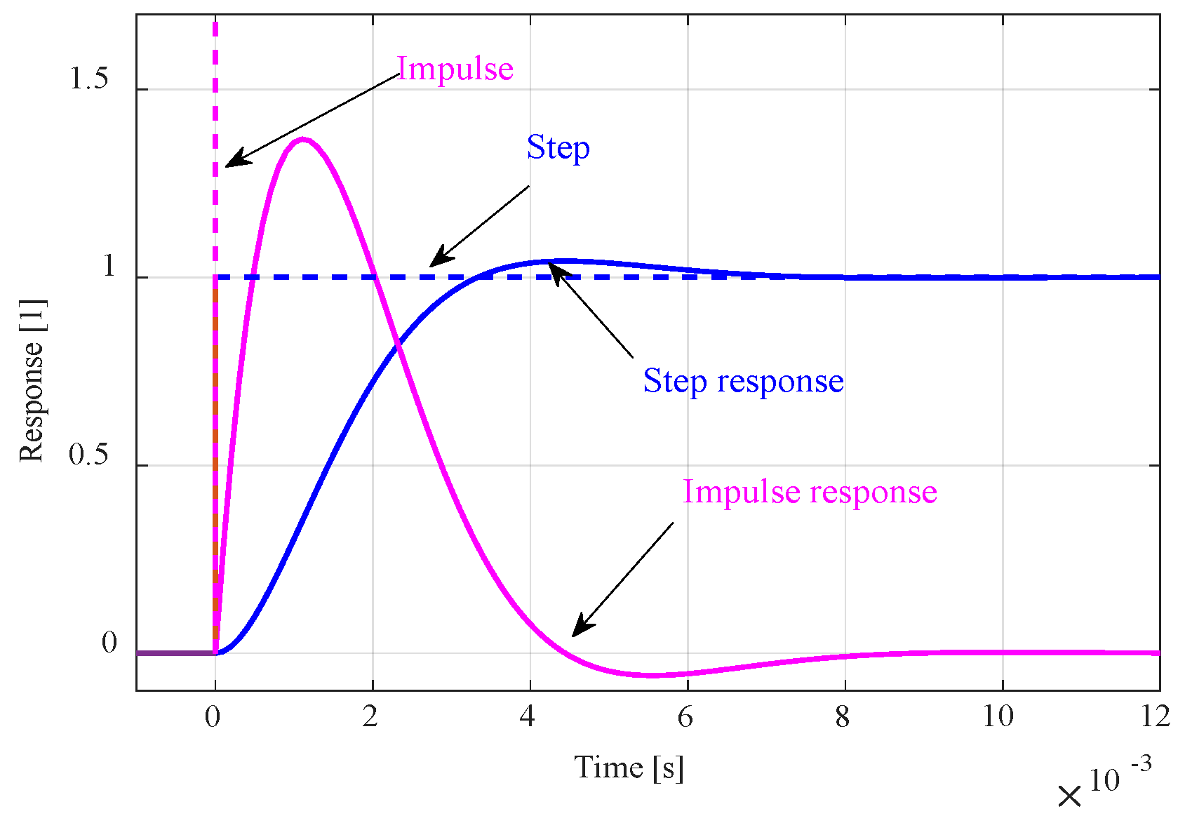
When DSISC occurs, the effective turns of the stator coil decrease, thus affecting the decrease of the gas gap magnetic motive force (MMF). The current in the stator no longer flows out from the fault line turns. A completely new loop arises in the stator coil, in which there is a reverse MMF generated by the DSISC.
The reverse magnetomotive force (MMF) generated by the short circuit ring current during DSISC occurs as a pulse. The reverse MMF when SSISC occurs is in the form of steps. The response maps of the pulses and steps are shown in
Figure 1.
The air gap magnetic flux density (MFD) of the synchronous generator is obtained by multiplying the air gap MMF and the air gap magnetic per unit area. Under normal operational conditions, the air gap magnetic field is evenly distributed, and the air gap distribution is shown in
Figure 2. The air gap magnetic can be expressed as:
In Equation (1): μ0 is the vacuum permeability, αm is the mechanical angle used to characterize the peripheral position of the air gap, t is the time, g0 is the average air gap length of the generator, and Λ0 is the air gap magnetic conductivity constant.
2.1. Impact of DSISC on MMF
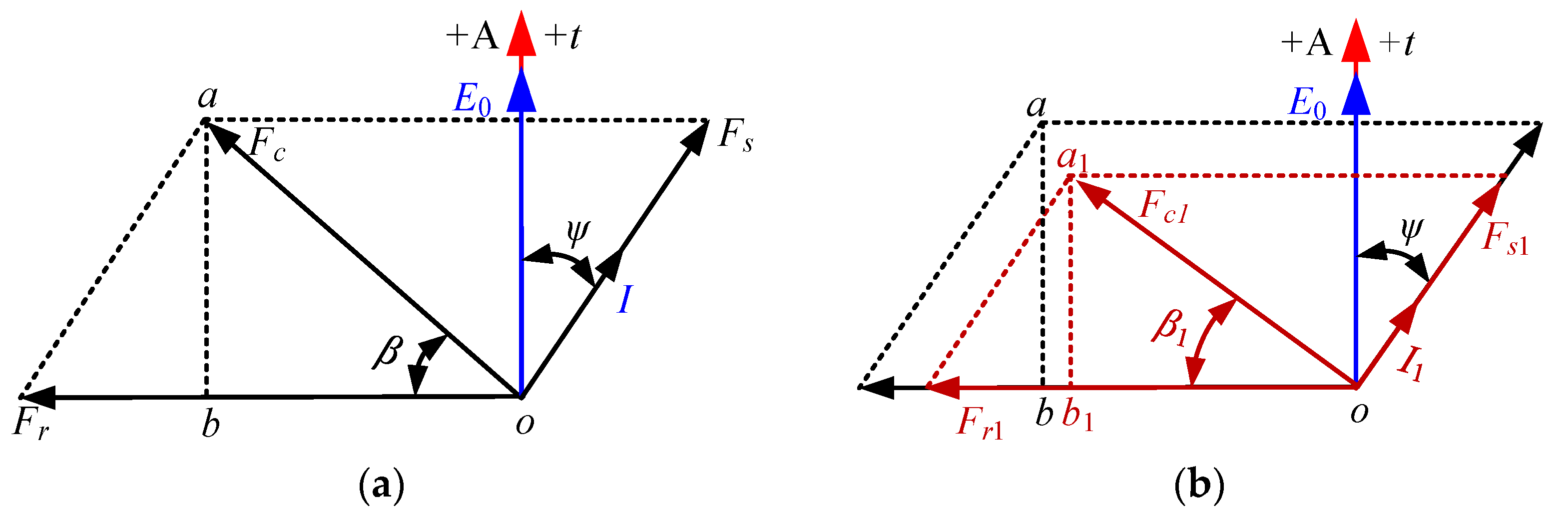
The vector diagram of the generator is shown in
Figure 3a, where
Fr is the MMF generated by the excitation winding.
Fs is the MMF generated by the stator winding.
Fc is the synthetic MMF,
ψ is the generator internal angle and
β is the angle between the main MMF and the armature reaction first harmonic potential.
The expression of air gap MMF under normal generator conditions of
Figure 3 is [
13]:
Formula fN is the generator air gap MMF under normal conditions. Fγ is the γth harmonic amplitude. If0 is the excitation current, η is the coefficient between the stator reaction first harmonic MMF and the main MMF and ω is the generator electric angle frequency.
2.2. Impact of DSISC on MFD
Equations (1) and (2), provides the MFD expression of the air gap under the normal working condition of the generator.
Equation (3) refers to the MFD of the normal working condition of the generator.
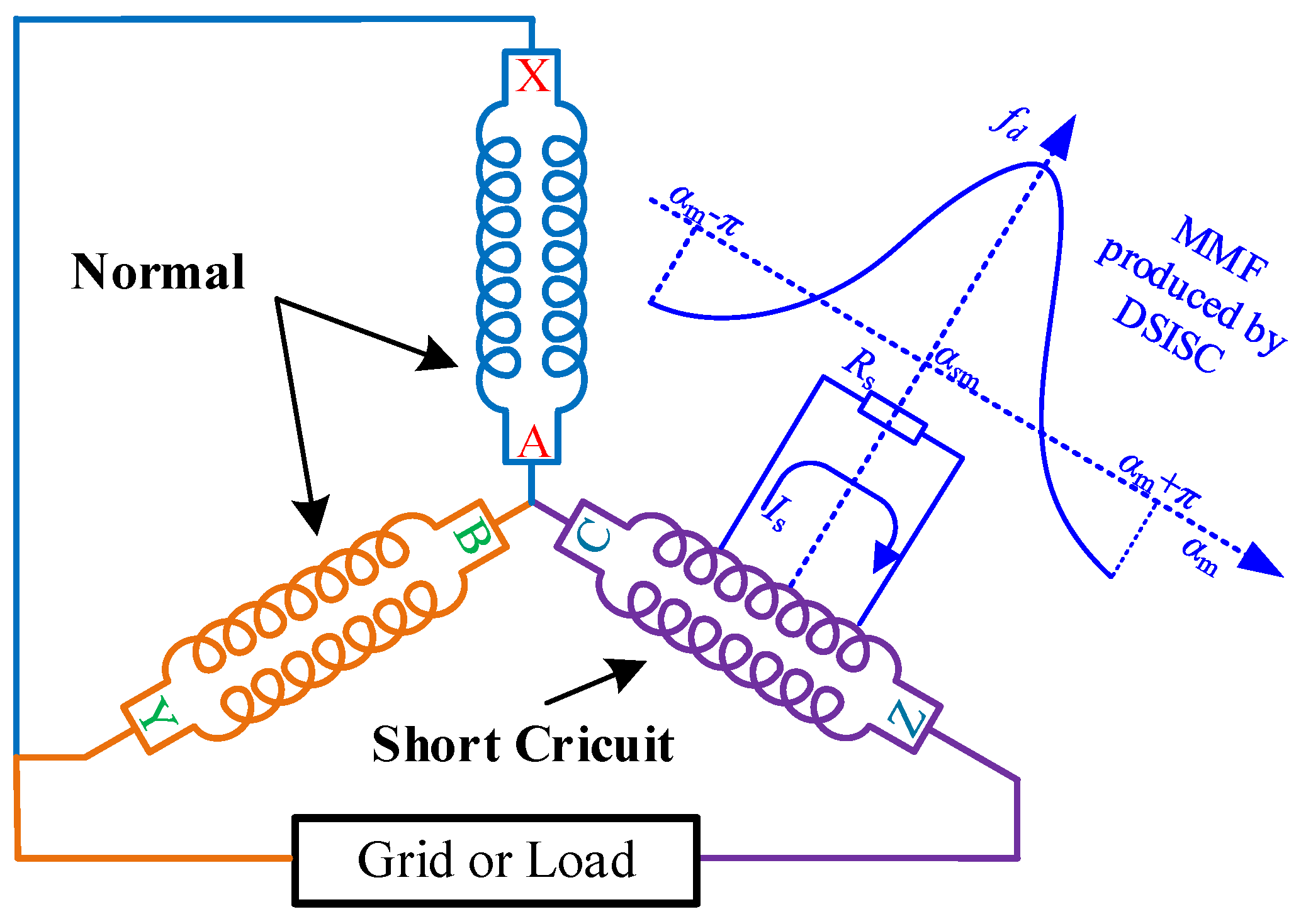
When there is a DSISC in the generator the model is as shown in
Figure 4. The occurrence of the DSISC will produce a pulse current
Is in the short circuit ring. Meanwhile, the short circuit ring produces a pulse vibration magnetic field,
fd, centered on the center of the short circuit turn. The
fd will become two magnetic fields in opposite rotational directions, distributed as a cosine function in space. See (4):
For the resulting reverse magnetic field, since it has a double rotational speed difference from the rotor, a new electromotive force will be produced with a frequency of 2 in the rotor winding. According to Lenz’s law, the equivalent excitation current after a short circuit can be expressed as:
In formula (5),
If2 is the current induced by the magnetic field
Fd in the rotor winding, which is closely related to the degree of the stator interturn short circuit, so the induced current
If2 can be expressed as:
The nm is the number of turns in the short circuit, wc is the number of turns per phase of the stator winding, and k is the degree of short circuit. Therefore, the greater the short circuit degree, the greater the induction current If2, and the excitation current decreases more obviously. Accordingly, the more the main (rotor) and first harmonic (stator armature reaction MMF) will be reduced.
After DSISC occurs, the generator MMF is shown in
Figure 3b, where
Fr1 and
Fs1 are the fixed rotor MMF after short circuit. Therefore, the synthetic MMF after short circuit can be expressed as:
Excluding the high harmonic effect, the air gap synthesis MMF can be further expressed as:
Linking (1) and (8), the MFD can be expressed as:
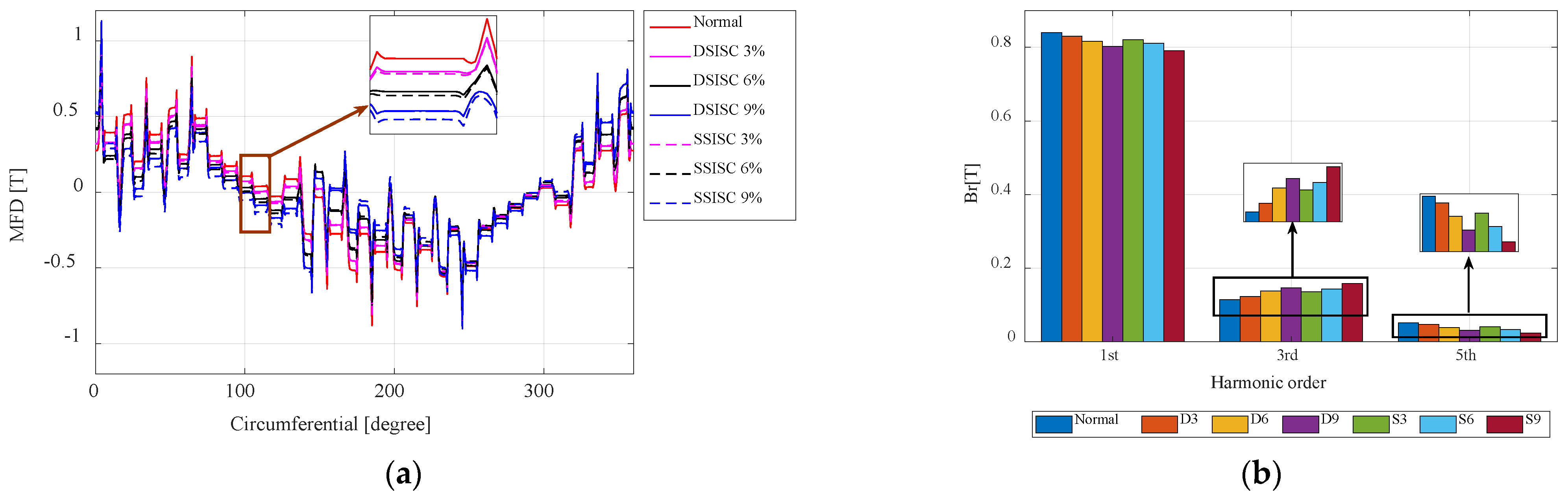
The amplitudes corresponding to each harmonic component of the MFD are shown in
Table 1. Therefore, with the increase of degree of the DSISC, the induction current increases, the air gap magnetic density decreases, and the third and fifth harmonics appear in the air gap magnetic density; the third harmonic in the air gap magnetic density increases, and the first harmonic and the fifth harmonic decrease.
2.3. Impact of DSISC on Current
The normal current expression of a generator is:
In Equation (10), l is the effective length of the stator magnetic wire cutting winding; Rs is the stator core inner diameter; nr is the generator speed; and Z is the reactance of the stator winding.
By putting Equation (9) into (10), the generator phase current expression under DSISC fault is obtained, as follows:
It can be seen that with the occurrence and degree of DSISC failure, the phase current amplitude of the generator will decrease.
2.4. Impact of DSISC on EMT
Based on the above analysis, according to the virtual displacement principle, the EMT studied in this paper can be expressed as:
According to this, the EMT depends on the square of the MFD. Qualitatively, the trend of EMT should be consistent with MFD, and the trend of squared operation will be more obvious.
3. FEA and Experimental Validation
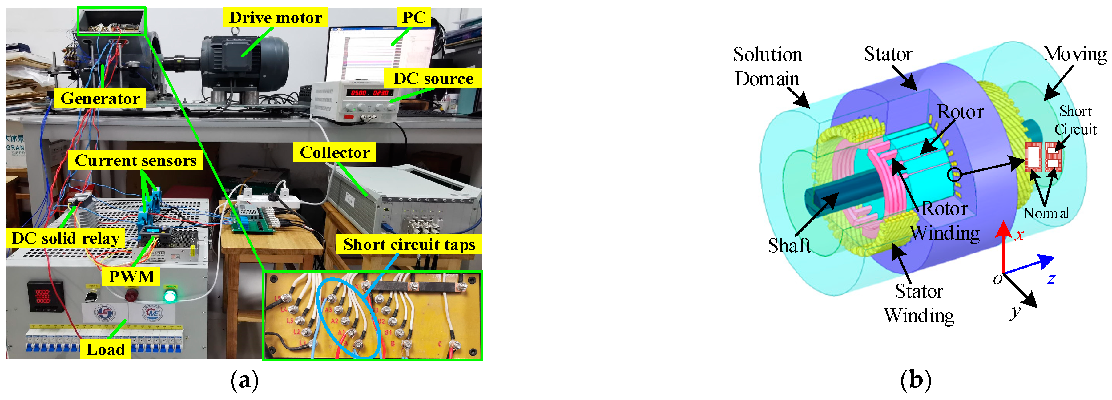
For this paper, the CS-5 hidden pole synchronous generator was studied. Finite-element analysis (FEA) and experiments on the generator characteristics under DSISC fault, are compared with SSISC fault. Specific parameters of the generator are listed in
Table 2.
This prototype generator was specifically designed and manufactured by ourselves and is able to simulate SISC. This paper establishes the finite element analysis (FEA) model in ANSYS Maxwell according to the CS-5 hidden pole synchronous generator design parameters, and verifies the stability and convergence of the model through previous calculations.
The experimental platform is shown in
Figure 5a, and the established FEA model is shown in
Figure 5b, where A
1–A
5 is the short circuit tap of the stator winding: 0% (A
1), 3% (A
2), 6% (A
3), 9% (A
4), and 100% (A
5).
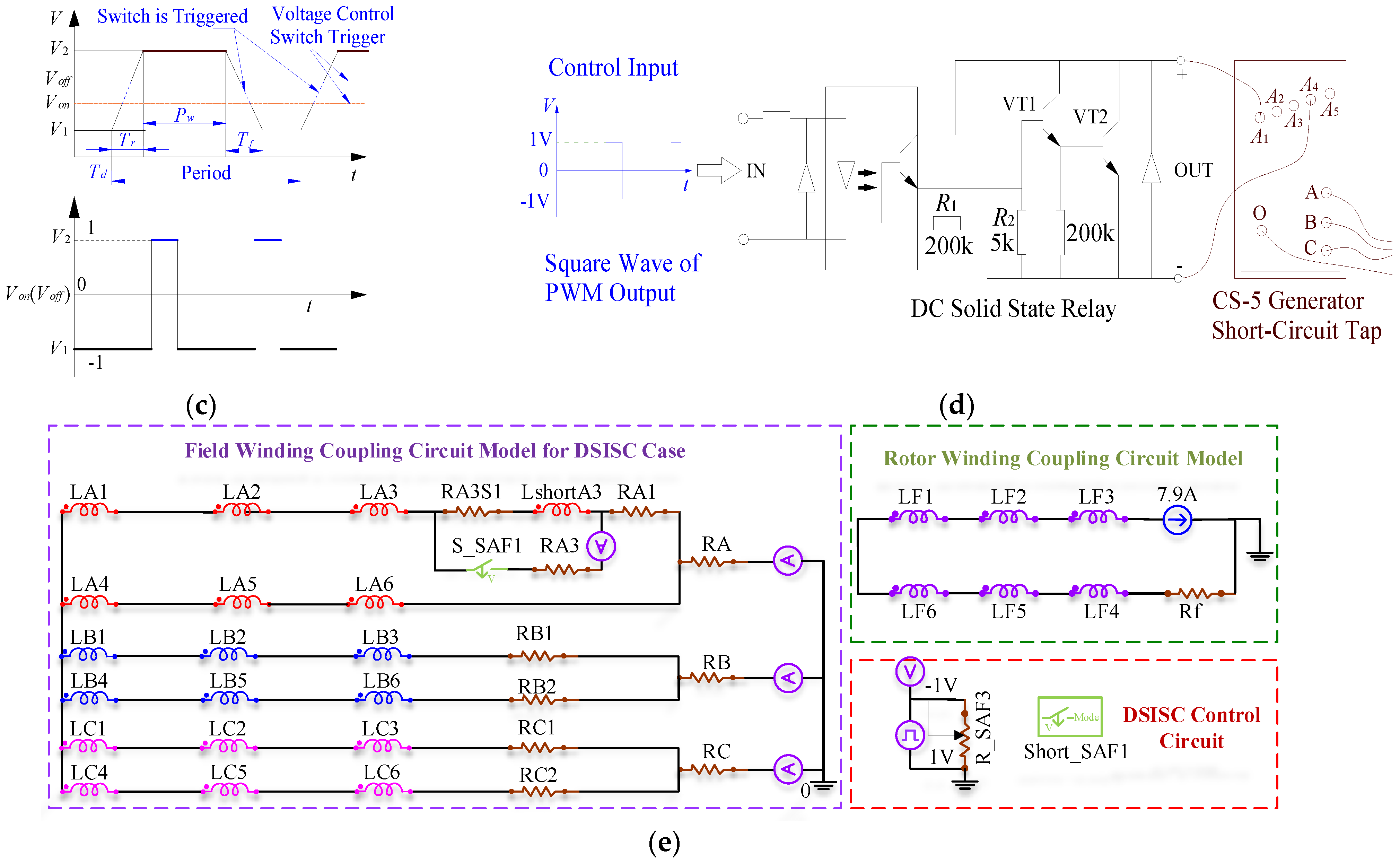
The DSISC fault experiment is realized by combining the PWM pulse generator and the DC solid-state relay. As shown in the test table, the DC solid state relay shorts the generator stator and connects the PWM to the control circuit portion of the DC solid state relay. The switching of normal and short circuit can be realized by setting the pulse cycle and peak of PWM, and adjusting the duty cycle of square wave can control the closing time of the DC solid-state relay. The method used in this paper can simulate a dynamic short circuit in actual high-speed operation.
In order to correspond to the simulation and experiment, the external coupling circuit has the same parameters in the actual generator. The schematic diagram of the external coupling circuit of the generator stator winding is shown in
Figure 5e. Experimental simulation of DSISC can be realized by using the pulse voltage unit to generate a specific pulse square wave, and controlling the short-circuit trigger switch S-A1. The specific simulation parameters are shown in
Figure 5d.
During finite element analysis, the external circuit contains parameters, such as normal and short circuit winding, and changes the resistance values of the corresponding resistors,
Rw and
Rf. Different degrees of fault simulation can be achieved. In
Figure 5c,
Td is the delay time,
Tr is the rise time,
Tf is the fall time,
Pw is the pulse width. The DSISC cycle corresponds to the pulse cycle. The trigger voltage of the control switch is represented by
Von. When the voltage value of the pulse voltage source is greater than
Von, the switch S_A1 operates and the stator coil is short circuited.
Voff represents the cut-off voltage of the voltage control switch. When the voltage value of the pulse voltage source is less than
Voff, the switch S_A1 is turned off and the stator coil is normal. The short-circuit portion of the duty cycle and DSISC frequency can be changed by adjusting
Pw and period. The short circuit section produces an external circuit of DSISC with a period of 20 ms (15% duty cycle), with the same settings used in the experiment.
In the experiment, DSISC simulation can be realized by short circuit to different degrees. In the FEA simulation, it corresponds to the experiment by changing the FEA model and external coupled circuit parameters.
Table 3 is the abbreviation of different cases.
4. Results Analysis and Discussion
From
Figure 6, when DSISC occurs and the degree intensifies, the overall amplitude of the MFD decreases.
The amplitude of the first harmonic and the fifth harmonic decreased gradually, but the third harmonic rose.
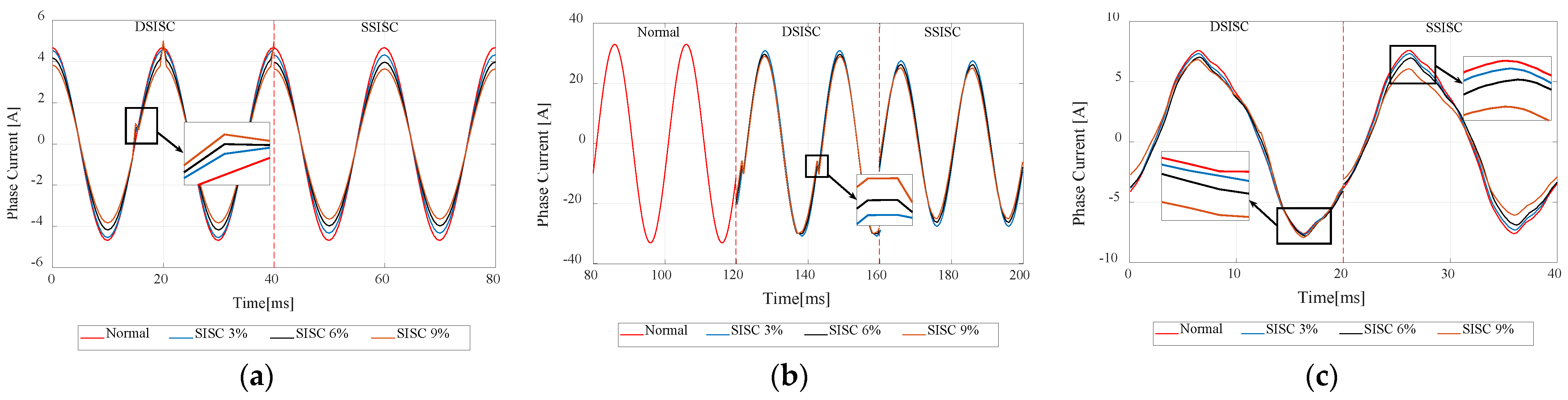
As can be seen from
Figure 7, when DSISC occurred, the generator phase current curve was also “compressed”, but was affected by the reverse current of the short circuit pulse, and the absolute value of the current at position 1 increased with the degree of short circuit. With a short degree of aggravation, the amplitude of the first harmonic and the fifth harmonic gradually decreased, but the third harmonic rose. The air gap magnetic density followed the phase current and agreed with Equation (11).
The theoretical, simulation, and experimental time-domain maps of the EMT are shown in
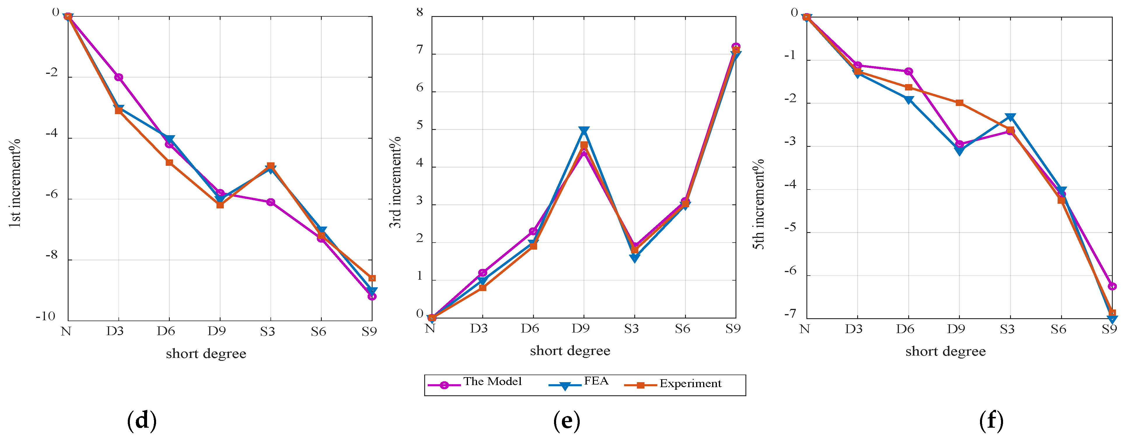
Figure 8. The results show that the waveform amplitude increased with the occurrence and degree of DSISC. It is shown in the frequency domain,
Figure 8, that the second, fourth, and sixth harmonic amplitudes increased as DSISC increased. The FEA results are in good agreement with the experimental data.
The influence on the EMT harmonic composition can be divided into two aspects. On the one hand, there are the tooth groove effect and the harmonic current. On the other hand, the radial eccentricity of the rotor leads to the long-term operation of the generator. Rotor radial eccentricity is the phenomenon of radial deviation between the moving center and the stator center of the rotor.
Although there is a data gap in the EMT frequency amplitude increment of theory, simulation and experiment, the overall development trend of the three data types is the same.
Compared with SSISC, DSISC, with the same short circuit degree, has less influence on MFD and phase current of the generator, but has a greater impact on EMT. The results correspond to the above theoretical analysis.
5. Conclusions
This paper presents a new fault analysis model for SISC of synchronous generators. Further, based on simulation and experiments on different DSISC degrees, the mechanical and electrical characteristics represented by phase current and EMT were studied. The results show that:
- (1).
When DSISC occurs, the overall amplitude of the generator circumference to MFD decreases, and the amplitude of the first harmonic and the fifth harmonic gradually reduce, but the third harmonic rises.
- (2).
The phase current time domain curve under DSISC fault will be affected by a short circuit, producing reverse pulse, and amplitude increases with short circuit. The harmonic change trend of the phase current is the same as that for the MFD.
- (3).
When DSISC occurs, the EMT fluctuation of the generator increases, and as the short circuit degree increases, the second, fourth and sixth harmonic amplitudes increase.
Author Contributions
Writing—original draft, M.-H.Q.; Writing—review & editing, Y.-L.H., X.-H.Y., X.-L.H., H.-P.W., M.-Y.J., C.G. and S.-T.W. All authors have read and agreed to the published version of the manuscript.
Funding
This research was funded by [National Natural Science Foundation of China] grant number [51777074] and [National Natural Science Foundation of China] grant number [52177042].
Institutional Review Board Statement
Not applicable.
Informed Consent Statement
Not applicable.
Data Availability Statement
Not applicable.
Conflicts of Interest
The authors declare no conflict of interest.
References
- Gandhi, A.; Corrigan, T.; Parsa, L. Recent Advances in Modeling and Online Detection of Stator Interturn Faults in Electrical Motors. IEEE Trans. Ind. Electron. 2011, 58, 1564–1575. [Google Scholar] [CrossRef]
- Jun-qing, L.; De-yan, W.; Li, M. The research of the inter-turn short circuit of the stator windings in doubly fed induction generator. In Proceedings of the 2011 International Conference on Electrical Machines and Systems, Beijing, China, 20–23 August 2011; pp. 1–4. [Google Scholar] [CrossRef]
- Prasad, B.J.C.; Ram, B.V.S. Inter-turn Fault Analysis of Synchronous Generator using Finite Element Method (FEM). Int. J. Recent Technol. Eng. 2013, 2, 150–156. [Google Scholar]
- Cameron, A.W.W. Diagnoses of A-C Generator Insulation Condition by Nondestructive Tests [includes discussion]. In Transactions of the American Institute of Electrical Engineers. Part III: Power Apparatus and Systems; IEEE: Piscataway, NJ, USA, 1952; Volume 71, pp. 263–274. [Google Scholar]
- Jun-qing, L.; Dong, W.; Long, H. Study of rotor winding inter-turn short circuit fault in doubly fed induction generator based on current signal spectrum analysis. In Proceedings of the 2013 International Conference on Electrical Machines and Systems (ICEMS), Busan, Korea, 26–29 October 2013; pp. 789–792. [Google Scholar] [CrossRef]
- Vinayak, A.B.; Alam, M.F.; Jagadanand, G.; Anand, A.K. Stator Inter Turn fault diagnosis by High-Frequency Modeling of Inverter Fed Induction Motor. In Proceedings of the 2020 IEEE International Conference on Power Electronics, Smart Grid and Renewable Energy (PESGRE2020), Cochin, India, 2–4 January 2020; pp. 1–5. [Google Scholar] [CrossRef]
- Çira, F.; Arkan, M.; Gümüş, B.; Goktas, T. Analysis of stator inter-turn short-circuit fault signatures for inverter-fed permanent magnet synchronous motors. In Proceedings of the IECON 2016—42nd Annual Conference of the IEEE Industrial Electronics Society, Florence, Italy, 23–26 October 2016; pp. 1453–1457. [Google Scholar] [CrossRef]
- Meng, Q.; He, Y. Mechanical Response Before and After Rotor Inter-turn Short-circuit Fault on Stator Windings in Synchronous Generator. In Proceedings of the 2018 IEEE Student Conference on Electric Machines and Systems, Huzhou, China, 14–16 December 2018; pp. 1–7. [Google Scholar] [CrossRef]
- Ojaghi, M.; Bahari, V. Rotor Damping Effects in Dynamic Modeling of Three-Phase Synchronous Machines Under the Stator Interturn Faults—Winding Function Approach. IEEE Trans. Ind. Appl. 2017, 53, 3020–3028. [Google Scholar] [CrossRef]
- Li, X.; Zheng, T.; Chi, Y.; Wang, W. Short Circuit Current Characteristic of Wind Generators. In Proceedings of the 2009 Asia-Pacific Power and Energy Engineering Conference, Wuhan, China, 27–31 March 2009; pp. 1–4. [Google Scholar] [CrossRef]
- Zhang, W.; He, Y.-L.; Li, Y.; Xu, M.-X.; Dai, D.-R. Detection of Ending Winding Wear Regulation Acting by Electromagnetic Force in Synchronous Generators under both SISC and SAGE Conditions. In Proceedings of the 2021 IEEE 4th Student Conference on Electric Machines and Systems (SCEMS), Huzhou, China, 1–3 December 2021; pp. 1–6. [Google Scholar] [CrossRef]
- He, Y.-L.; Xu, M.-X.; Zhang, W.; Wang, X.-L.; Lu, P.; Gerada, C.; Gerada, D. Impact of Stator Interturn Short Circuit Position on End Winding Vibration in Synchronous Generators. IEEE Trans. Energy Convers. 2021, 36, 713–724. [Google Scholar] [CrossRef]
- Bouzid, M.B.K.; Champenois, G.; Bellaaj, N.M.; Signac, L.; Jelassi, K. An effective neural approach for the automatic location of stator interturn faults in induction motor. IEEE Trans. Ind. Electron. 2008, 55, 4277–4289. [Google Scholar] [CrossRef]
- Roshanfekr, R.; Jalilian, A. Experimental validation of MEC modeling for stator and rotor winding faults in WRIMs. In Proceedings of the 2014 International Conference on Electrical Machines (ICEM), Berlin, Germany, 2–5 September 2014; pp. 1601–1607. [Google Scholar] [CrossRef]
- Liang, Y. Diagnosis of inter-turn short-circuit stator winding fault in PMSM based on stator current and noise. In Proceedings of the 2014 IEEE International Conference on Industrial Technology (ICIT), Busan, Korea, 26 February–1 March 2014; pp. 138–142. [Google Scholar] [CrossRef]
- Alwodai, A.; Shao, Y.; Yuan, X.; Ahmed, M.; Gu, F.; Ball, A.D. Inter-turn short circuit detection based on modulation signal bispectrum analysis of motor current signals. In Proceedings of the 2013 19th International Conference on Automation and Computing, London, UK, 13–14 September 2013; pp. 1–6. [Google Scholar]
- Shuting, W.; Yonggang, L.; Heming, L.; Guiji, T. A Compositive Diagnosis Method on Turbine-Generator Rotor Winding Inter-turn Short Circuit Fault. In Proceedings of the 2006 IEEE International Symposium on Industrial Electronics, Montreal, QC, Canada, 9–13 July 2006; pp. 1662–1666. [Google Scholar] [CrossRef]
- He, Y.; Zhang, Y.; Xu, M.; Wang, X.; Xiong, J. A New Hybrid Model for Electromechanical Characteristic Analysis under SISC in Synchronous Generators. IEEE Trans. Ind. Electron. 2020, 67, 2348–2359. [Google Scholar] [CrossRef]
- Heming, L.; Shuting, W.; Yonggang, L.; Aimeng, W. Condition monitoring of generator stator winding inter-turn short circuit fault based on electrically excited vibration. In Proceedings of the IEEE International Conference on Electric Machines and Drives, San Antonio, TX, USA, 15 May 2005; pp. 1–4. [Google Scholar] [CrossRef]
- Hao, L.; Wu, J.; Zhou, Y. Theoretical Analysis and Calculation Model of the Electromagnetic Torque of Nonsalient-Pole Synchronous Machines with Interturn Short Circuit in Field Windings. IEEE Trans. Energy Convers. 2015, 30, 110–121. [Google Scholar] [CrossRef]
- Obeid, N.H.; Boileau, T.; Nahid-Mobarakeh, B. Modeling and Diagnostic of Incipient Interturn Faults for a Three-Phase Permanent Magnet Synchronous Motor. IEEE Trans. Ind. Appl. 2016, 52, 4426–4434. [Google Scholar] [CrossRef]
| Publisher’s Note: MDPI stays neutral with regard to jurisdictional claims in published maps and institutional affiliations. |
© 2022 by the authors. Licensee MDPI, Basel, Switzerland. This article is an open access article distributed under the terms and conditions of the Creative Commons Attribution (CC BY) license (https://creativecommons.org/licenses/by/4.0/).


 ,
, 


