
An Underwater Glider with Muscle—Actuated Buoyancy Control and Caudal Fin Turning

 , , and
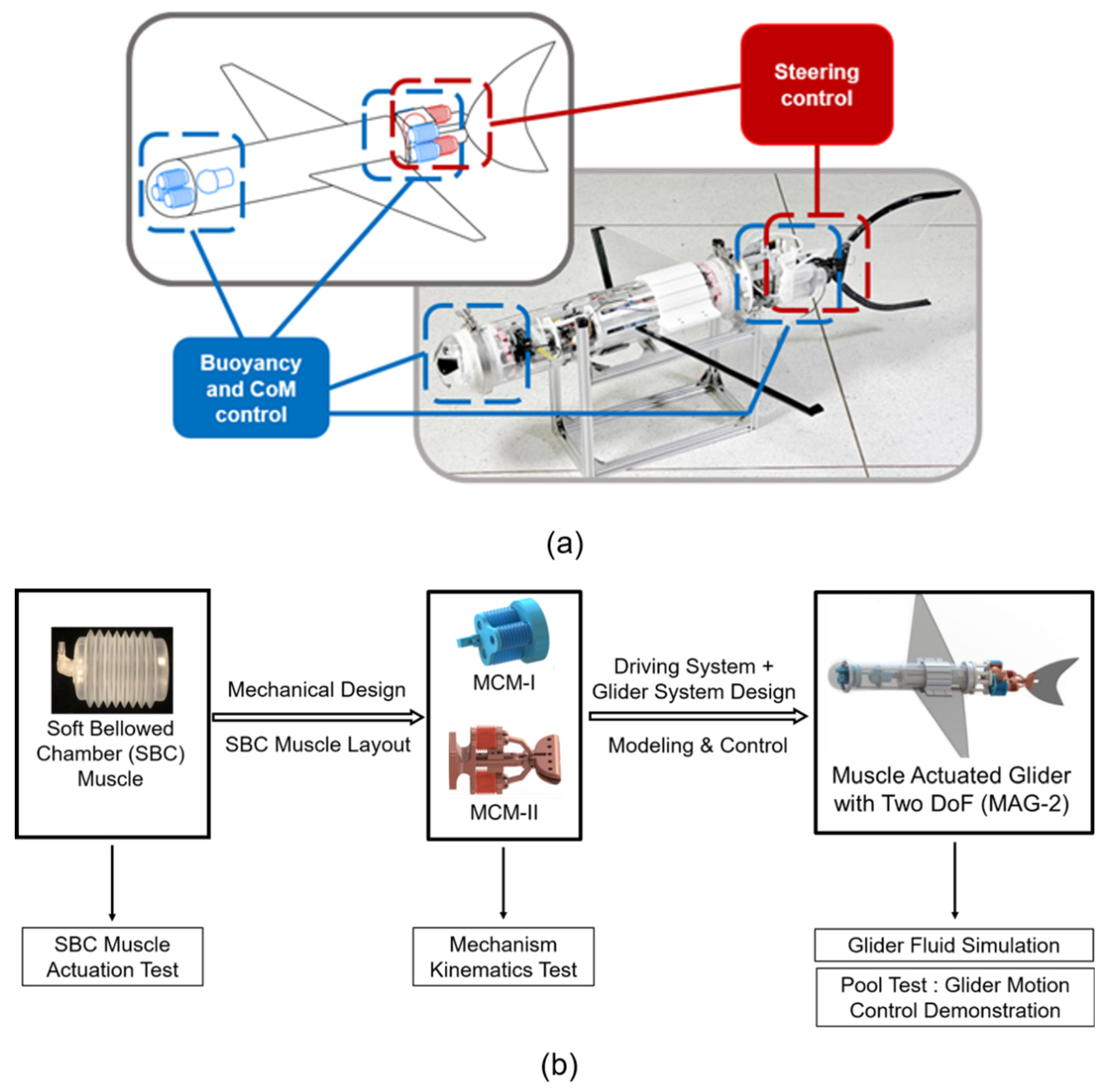
Abstract
:1. Introduction
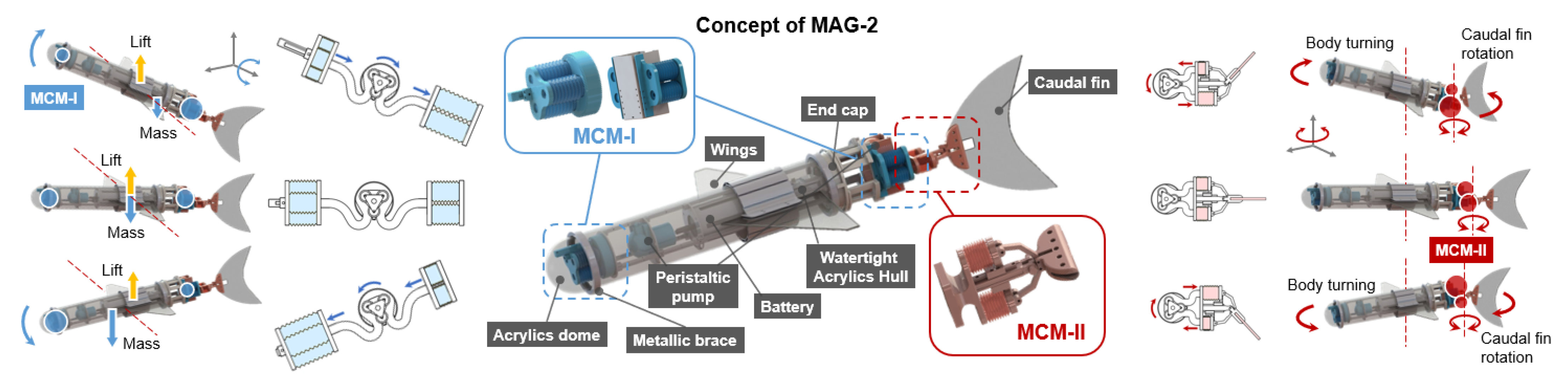
2. Principle of Operation for the MAG-2
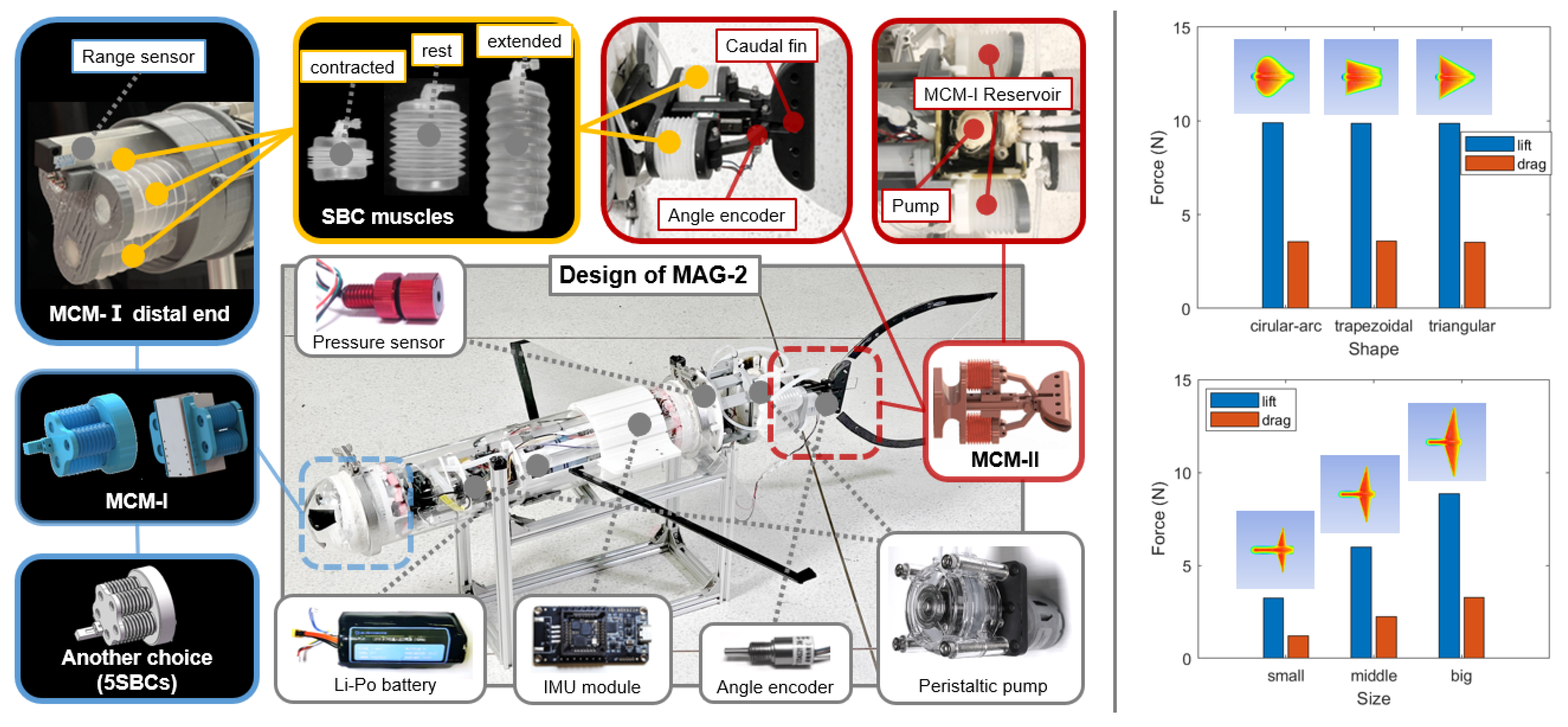
3. System Design of the MAG-2
3.1. Overall System Layout
3.2. Modularized Actuation Mechanisms
3.3. Valve-Free Efficient Actuation
3.4. Wings and Tails
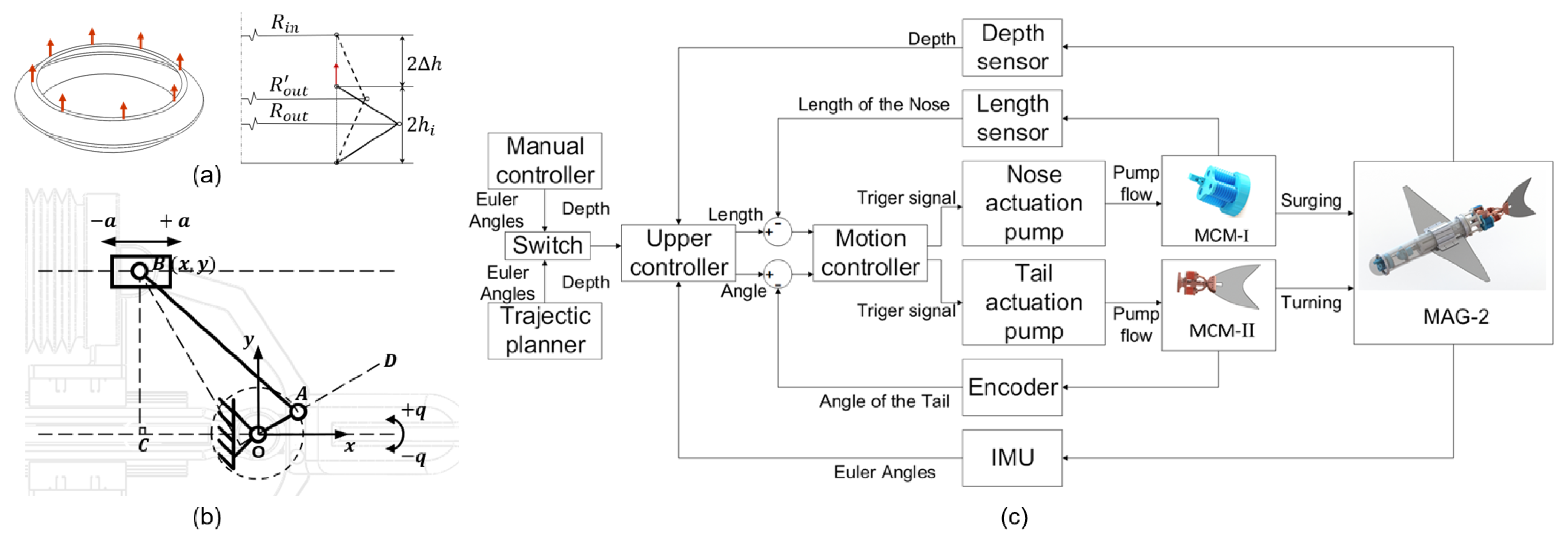
4. Modeling and Control
4.1. Model of Single SBC

4.2. Model of the MCM-I for Buoyancy Adjustment
4.3. Model of the MCM-II for Tail Turning
4.4. Cascaded Motion Controller for the MAG-2
4.4.1. Inner Layer Controller: Single Pump-SBC Actuation
4.4.2. Outer Layer Controller: Diving and Turning Control
5. Experimental Validation
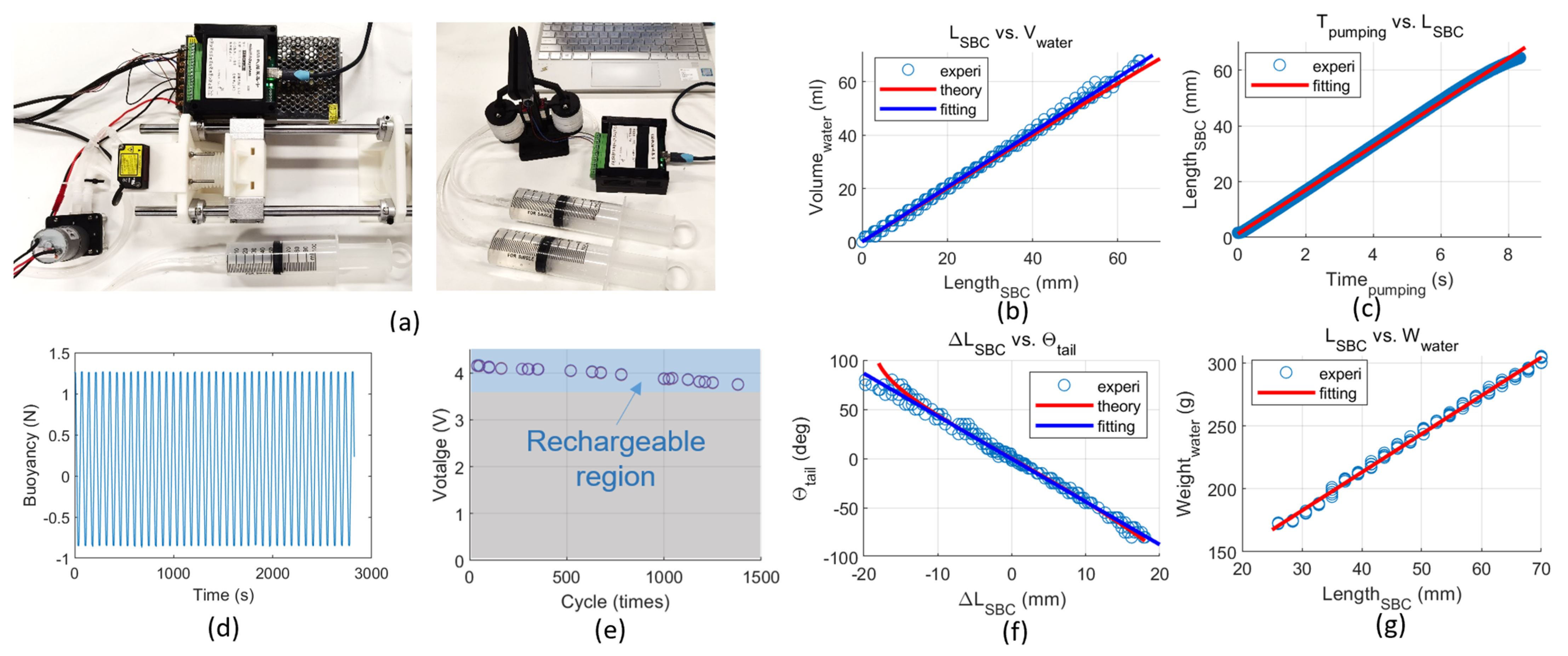
5.1. Experimental Performance of the SBC Actuators
5.2. Experimental Performance of the MCM-I Nose Mechanism
5.3. Experimental Performance of the MCM-II Caudal Fin
5.4. Energy Efficiency Experiment
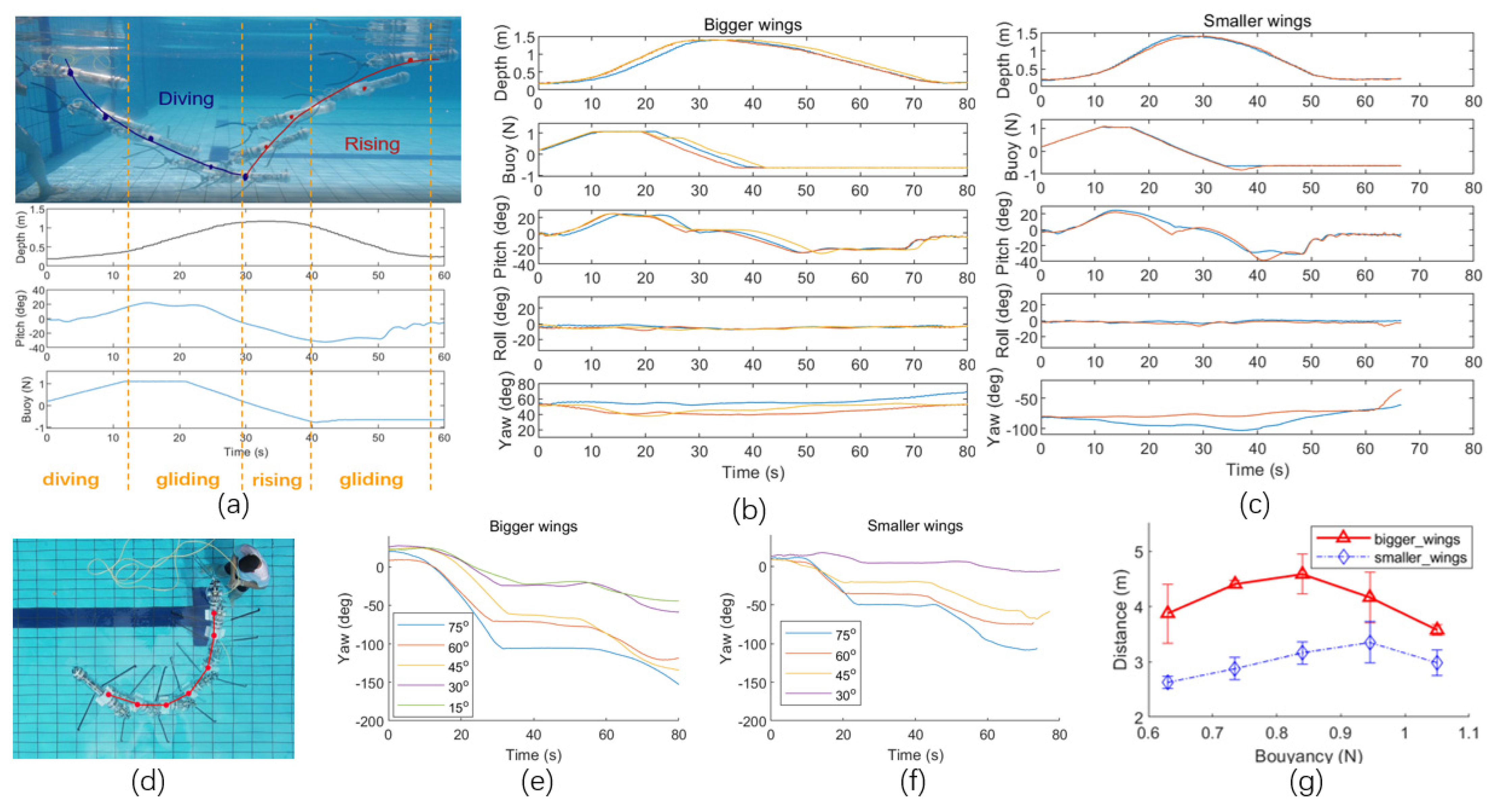
5.5. Field Tests of the MAG-2
6. Conclusions and Future Work
Supplementary Materials
Author Contributions
Funding
Institutional Review Board Statement
Informed Consent Statement
Data Availability Statement
Conflicts of Interest
References
- Wang, X.; Shang, J.; Luo, Z.; Tang, L.; Zhang, X.; Li, J. Reviews of power systems and environmental energy conversion for unmanned underwater vehicles. Renew. Sustain. Energy Rev. 2012, 16, 1958–1970. [Google Scholar] [CrossRef]
- Button, R.W.; Kamp, J.; Curtin, T.B.; Dryden, J. A Survey of Missions for Unmanned Undersea Vehicles; National Defense Research Institute: Santa Monica, CA, USA, 2009; Volume 223. [Google Scholar]
- Gafurov, S.A.; Klochkov, E.V. Autonomous unmanned underwater vehicles development tendencies. Procedia Eng. 2015, 106, 141–148. [Google Scholar] [CrossRef] [Green Version]
- Sahoo, A.; Dwivedy, S.K.; Robi, P.S. Advancements in the field of autonomous underwater vehicle. Ocean Eng. 2019, 181, 145–160. [Google Scholar] [CrossRef]
- Petillot, Y.R.; Antonelli, G.; Casalino, G.; Ferreira, F. Underwater robots: From remotely operated vehicles to intervention-autonomous underwater vehicles. IEEE Robot. Autom. Mag. 2019, 26, 94–101. [Google Scholar] [CrossRef]
- Wadoo, S.; Kachroo, P. Autonomous Underwater Vehicles: Modeling, Control Design and Simulation; CRC Press: Boca Raton, FL, USA, 2017. [Google Scholar]
- Simetti, E.; Casalino, G.; Torelli, S.; Sperinde, A.; Turetta, A. Floating underwater manipulation: Developed control methodology and experimental validation within the TRIDENT project. J. Field Robot. 2014, 31, 364–385. [Google Scholar] [CrossRef]
- PowerVision, Inc. PowerRay. Available online: https://www.powervision.me/en/product/powerray (accessed on 3 September 2021).
- Rudnick, D.L. Ocean Research Enabled by Underwater Gliders. Annu. Rev. Mar. Sci. 2016, 8, 519–541. [Google Scholar] [CrossRef]
- Sherman, J.; Davis, R.E.; Owens, W.B.; Valdes, J. The autonomous underwater glider “Spray”. IEEE J. Ocean. Eng. 2001, 26, 437–446. [Google Scholar] [CrossRef] [Green Version]
- Eriksen, C.C.; Osse, T.J.; Light, R.D.; Wen, T.; Lehman, T.W.; Sabin, P.L.; Ballard, J.W.; Chiodi, A.M. Seaglider: A long-range autonomous underwater vehicle for oceanographic research. IEEE J. Ocean. Eng. 2001, 26, 424–436. [Google Scholar] [CrossRef] [Green Version]
- Webb, D.C.; Simonetti, P.J.; Jones, C.P. SLOCUM: An underwater glider propelled by environmental energy. IEEE J. Ocean. Eng. 2001, 26, 447–452. [Google Scholar] [CrossRef]
- Xue, D.Y.; Wu, Z.L.; Wang, Y.H.; Wang, S.X. Coordinate Control, Motion Optimization and Sea Experiment of a Fleet of Petrel-II Gliders. Chin. J. Mech. Eng. 2018, 31, 1–15. [Google Scholar] [CrossRef] [Green Version]
- Zhang, F.; Thon, J.; Thon, C.; Tan, X. Miniature underwater glider: Design, modeling, and experimental results. In Proceedings of the IEEE International Conference on Robotics and Automation, Saint Paul, MN, USA, 14–18 May 2012; pp. 4904–4910. [Google Scholar]
- Petritoli, E.; Leccese, F.; Cagnetti, M. A high accuracy buoyancy system control for an underwater glider. In Proceedings of the IEEE International Workshop on Metrology for the Sea: Learning to Measure Sea Health Parameters (MetroSea), Bari, Italy, 8–10 October 2018; pp. 257–261. [Google Scholar]
- Ribeiro, G.A.; Pinar, A.; Wilkening, E.; Ziaeefard, S.; Mahmoudian, N. A multi-level motion controller for low-cost underwater gliders. In Proceedings of the IEEE International Conference on Robotics and Automation (ICRA), Seattle, WA, USA, 26–30 May 2015; pp. 1131–1136. [Google Scholar]
- Mitchell, B.; Wilkening, E.; Mahmoudian, N. Developing an underwater glider for educational purposes. In Proceedings of the IEEE International Conference on Robotics and Automation, Karlsruhe, Germany, 6–10 May 2013; pp. 3423–3428. [Google Scholar]
- Yu, J.C.; Zhang, A.Q.; Jin, W.M.; Chen, Q.; Tian, Y.; Liu, C.J. Development and experiments of the sea-wing underwater glider. China Ocean Eng. 2011, 25, 721–736. [Google Scholar] [CrossRef] [Green Version]
- Williams, A. Design of a Low-Cost Open-Source Underwater Glider. engrXiv 2018. [Google Scholar] [CrossRef]
- Ranganathan, T.; Aravazhi, S.; Mishra, S.; Thondiyath, A. Design and analysis of a novel underwater glider-robuoy. In Proceedings of the IEEE International Conference on Robotics and Automation (ICRA), Brisbane, QLD, Australia, 21–25 May 2018; pp. 2089–2094. [Google Scholar]
- Yu, P.; Wang, T.; Zhou, H.; Shen, C. Dynamic modeling and three-dimensional motion simulation of a disk type underwater glider. Int. J. Nav. Arch. Ocean Eng. 2018, 10, 318–328. [Google Scholar] [CrossRef]
- Krieg, M.; Sledge, I.; Mohseni, K. Design considerations for an underwater soft-robot inspired from marine invertebrates. Bioinspiration Biomim. 2015, 10, 065004. [Google Scholar] [CrossRef] [Green Version]
- Chen, G.; Yang, X.; Zhang, X.; Hu, H. Water hydraulic soft actuators for underwater autonomous robotic systems. Appl. Ocean Res. 2021, 109, 102551. [Google Scholar] [CrossRef]
- Polygerinos, P.; Correll, N.; Morin, S.A.; Mosadegh, B.; Onal, C.D.; Petersen, K.; Cianchetti, M.; Tolley, M.T.; Shepherd, R.F. Soft robotics: Review of fluid-driven intrinsically soft devices; manufacturing, sensing, control, and applications in human-robot interaction. Adv. Eng. Mater. 2017, 19, 1700016. [Google Scholar] [CrossRef]
- Wang, L.; Wang, Z. Mechanoreception for soft robots via intuitive body cues. Soft Robot. 2020, 7, 198–217. [Google Scholar] [CrossRef]
- Tan, Q.; Chen, Y.; Liu, J.; Zou, K.; Yi, J.; Liu, S.; Wang, Z. Underwater Crawling Robot with Hydraulic Soft Actuators. Front. Robot. AI 2021, 8, 688697. [Google Scholar] [CrossRef]
- Marchese, A.D.; Onal, C.D.; Rus, D. Autonomous soft robotic fish capable of escape maneuvers using fluidic elastomer actuators. Soft Robot. 2014, 1, 75–87. [Google Scholar] [CrossRef] [Green Version]
- Liu, J.; Hu, H. Biological inspiration: From carangiform fish to multi-joint robotic fish. J. Bionic Eng. 2010, 7, 35–48. [Google Scholar] [CrossRef]
- Yu, J.; Tan, M.; Wang, S.; Chen, E. Development of a biomimetic robotic fish and its control algorithm. IEEE Trans. Syst. Man Cybern. Part B Cybern. 2004, 34, 1798–1810. [Google Scholar] [CrossRef]
- Gupta, S.; Ng, T.; Shen, Z.; Wang, Z. Development of High Performance Mechanical Robotic Fish. In Proceedings of the Advanced Maritime Engineering Conference (AMEC) & Pan Asian Association of Maritime Engineering Societies (PAAMES) Meeting, Busan, Korea, 9–12 October 2018; The Society of Naval Architects of Korea (SNAK): Daejeon, Korea, 2018. [Google Scholar]


Publisher’s Note: MDPI stays neutral with regard to jurisdictional claims in published maps and institutional affiliations. |
© 2022 by the authors. Licensee MDPI, Basel, Switzerland. This article is an open access article distributed under the terms and conditions of the Creative Commons Attribution (CC BY) license (https://creativecommons.org/licenses/by/4.0/).
Share and Cite
Wang, B.; Chen, Y.; Wu, Y.; Lin, Y.; Peng, S.; Liu, X.; Wu, S.; Liu, S.; Yi, J.; Polygerinos, P.; et al. An Underwater Glider with Muscle—Actuated Buoyancy Control and Caudal Fin Turning. Machines 2022, 10, 381. https://doi.org/10.3390/machines10050381
Wang B, Chen Y, Wu Y, Lin Y, Peng S, Liu X, Wu S, Liu S, Yi J, Polygerinos P, et al. An Underwater Glider with Muscle—Actuated Buoyancy Control and Caudal Fin Turning. Machines. 2022; 10(5):381. https://doi.org/10.3390/machines10050381
Chicago/Turabian StyleWang, Biao, Yishan Chen, Yige Wu, Yi Lin, Sijie Peng, Xiaohan Liu, Shijian Wu, Sicong Liu, Juan Yi, Panagiotis Polygerinos, and et al. 2022. "An Underwater Glider with Muscle—Actuated Buoyancy Control and Caudal Fin Turning" Machines 10, no. 5: 381. https://doi.org/10.3390/machines10050381