Article

A Compatible Design of a Passive Exoskeleton to Reduce the Body–Exoskeleton Interaction Force

Department of Mechanical and Engineering, Beijing Institute of Technology, Haidian, Beijing 100081, China
*
Author to whom correspondence should be addressed.
Machines 2022, 10(5), 371; https://doi.org/10.3390/machines10050371
Submission received: 16 April 2022 / Revised: 10 May 2022 / Accepted: 11 May 2022 / Published: 13 May 2022
(This article belongs to the Section Automation and Control Systems)

Abstract

:
In the research and development of a passive exoskeleton, the body–exoskeleton coupling mode is a key point to reduce the interaction force and realize the efficient assistance of the exoskeleton. The purpose of this paper was to explore a cooperative movement mode between human and passive exoskeleton for reducing the body–exoskeleton interaction force. Firstly, through the research of the body–exoskeleton interactive mode, we analyzed the kinematic and dynamic constraint of the exoskeleton and established a dynamic model of the body–exoskeleton system. On this basis, the characteristic of the body–exoskeleton interaction force was analyzed; then, we put forward a mode that uses human gravity and load weight to maintain the stability of the exoskeleton’s movement to achieve the goal of reducing the interaction force. Based on the human–exoskeleton integrated mode, we constructed a mechanical model and simulated the change in interaction force in this mode; the simulation results showed that the interaction force at the lower leg was 98.5% less than that of the pure mechanical exoskeleton. Finally, we developed a prototype that was made of plastic parts and finished the experiment by walking with a load of 30 kg. The experimental results showed that this mode reduced the body–exoskeleton interaction force by 65.1%, which verified the effectiveness of the body–exoskeleton coupling mode preliminarily. The research results provided a new analytical approach for the design of a passive exoskeleton, and its improvement effect could be extended from the lower leg of the body–exoskeleton to the thigh or trunk, and guide the design of a passive exoskeleton.

1. Introduction

Exoskeletons are mechanical and electrical devices that are worn by an operator and are designed to increase the body’s physical performance. The development of an exoskeleton robot involves many fields [1], including military [2], medical [3], industry [4], and has formed many types of products and prototypes such as Stride Management Assist (SMA) and ankle foot orthoses (AFO) [5,6]. As a kind of technical equipment combined with the human body, the exoskeleton robot and the human body are connected by the body–exoskeleton binding, which ensures the two move synchronously and constructs the human–exoskeleton integrated system. Obviously, one of the keys to realizing the assistance effect of an exoskeleton robot was to study the coupled relation of body–exoskeleton systems [7].
In recent years, the research of the coupling mechanism between an exoskeleton robot and the human body has mainly included two aspects: first, investigating the cooperative motion of the body–exoskeleton system; second, analyzing the body–exoskeleton interaction force and maintaining the stable motion of the exoskeleton. In the first, considering the asynchronization of body–exoskeleton movement would lead to uncontrollable internal forces [8,9], the design of a soft exoskeleton was an efficient solution as these devices are lighter, more flexible, and offer greater user comfort [10,11,12]; however, in the rigid exoskeleton, some passive or active rotational and translational degrees of freedom (DOF) are usually added in the motion chain of the exoskeleton to align the active exoskeleton joint with the human joint [13,14,15,16,17]. In order to verify the synchronicity of body–exoskeleton movement, flexible pressure sensors were used to detect the change in body–exoskeleton negative forces to evaluate the influence of kinematics design on the body–exoskeleton negative forces [18,19], and it has been proved that the design of a passive joint reduced the internal force effectively [20,21].
In the latter, the body–exoskeleton interaction force was related with the joint drive of the exoskeleton. When the joints of the exoskeleton were driven by motors, the exoskeleton could realize its stable movement by its driving system, which eases the burden of the human body in the movement of the human–exoskeleton system [22,23,24]. Furthermore, there was an exoskeleton with integration of actuated and passive joints, for example, Shanghai Jiao Tong University designed the SJTU-EX whose hip flexion and extension, hip adduction and abduction, and flexion and extension of the ankle joint were by active driving, while the movement of the knee joint was completed by the spring [25]. Yu [26] designed an exoskeleton whose knee joint was active and whose hip and ankle joint were passive, among which an embedded spring in the hip joint was designed to assist the balance of the load in the coronal plane, while the ankle joint was embedded with springs to assist the movement of dorsal flexion in the sagittal plane. In general, the active exoskeleton was driven by its own electromechanical system, which produced less interaction force between human and exoskeleton [27]. However, the active exoskeleton had some disadvantages that included large weight, limited battery power and lack of coordination with human movement, which made it difficult to use in practice [28].
As opposed to an active exoskeleton, passive exoskeletons have been put into practice successfully in different scenarios [29,30]. Given the assistant method of the passive exoskeleton, the elastic element has been used to assist human movement through combining the characteristics of human movement [31]. For example, Hidayah [32] used a coil-spring to assist knee extension. Walsh [19] designed a mechanical exoskeleton that has ankle and hip springs and a knee variable damper to bear a load. The deformation of the spring in the passive exoskeleton was based on the displacement of human joint movement; then, the elastic potential energy of the spring was released to assist human movement. It is noteworthy that using the spring to assist human movement was different to that of using the spring to help the exoskeletal motion, especially for the exoskeleton walking with load. Yu et al. pointed out that [26] the stance phase of human walking, as seen in Figure 1, is divided into the dorsiflexion section, where power absorption takes place, and the plantarflexion section, where power generation occurs, and they proposed a mechanism in which the power stored during dorsiflexion motion using the spring was used during plantarflexion. It could be seen that this mechanism provided for maintaining the ankle motion of their exoskeleton; the downside of it was that it provided nothing for human walking propulsion. Another important point was the spring stiffness; the right stiffness of the spring could maintain exoskeleton motion or help human movement to the greatest extent. Springs that were too compliant or too stiff had little benefit and even affected human movement and consumed human energy. They obtained the spring stiffness from the relationship between human ankle angle and human ankle moment. To our knowledge, the ankle torque of the exoskeleton was varied with the weight of the exoskeleton; therefore, the spring stiffness should be obtained from the torque of the ankle joint under the rated load of the exoskeleton, and its characteristics were worth studying.
In this paper, we propose an improved method that, through the combination of human gravity and load weight, maintains the movement of the passive exoskeleton ankle joint, so as to reduce the power requirement from the human body in the process of carrying weight and helping human movement. Firstly, this paper analyzed the dynamics of the human body during walking with the passive exoskeleton, and then studied the characteristics of the exoskeleton joint torque and the influence of the exoskeleton on the human body. With that, we presented taking the spring as a “bridge” to connect the human gravity and load weight. First, the human gravity acted downward on the exoskeleton shoes, which formed a downward pull on the spring, and the load weight acted on the exoskeleton leg, which formed an upward pull on the spring; then, the spring was stretched by the human gravity and load weight. Finally, the stretched spring force could maintain the balance of the exoskeleton ankle motion and achieve the reduction in the driving force of the calf muscle for the exoskeleton, and the stretched spring was used to assist the ankle plantar flexion in the late stance phase. Finally, we developed a lightweight prototype with a weight of 3.15 kg, which was made by the glass-fiber-reinforced polyamide, to test the actual effect [33], and through the experiment, the change in body–exoskeleton interaction forces was collected by the pressure-testing device and analyzed during walking with the passive exoskeleton, which verified the original intention of this paper.

2. The Dynamics of Body–Exoskeleton Coupling System

In this section, the dynamics of the exoskeleton system and the body–exoskeleton interaction force are studied in detail. Furthermore, we analyze the influence of body–exoskeleton interaction force on the human body and the exoskeleton system, and propose the redistribution of the body–exoskeleton interaction force to improve the body–exoskeleton coupling system.

2.1. The Kinematics and Dynamics of Exoskeleton System

The exoskeleton was worn on the human body and its movement form was limited by human movement. Therefore, understanding the movement of the human body was the design premise of the exoskeleton. The analysis of human movement in the literature was sufficient; for example, the human trunk was usually equivalent to a component with multiple degrees of freedom (DOFs) and was connected to the pelvis, while the pelvis had six independent DOFs that could translate and rotate independently [34]. In the human lower limbs, the movement of the hip joint had three DOFs [35], and the knee joint was equivalent to one DOF in the sagittal plane [36], the ankle joint had two rotational DOFs [35], as shown in Figure 2 (left). Based on this basic cognition of a human’s main movement, we built a simple body–exoskeleton integrated model; the human body has six DOFs on the connected point between the trunk and pelvis, the hip joint in the pelvis was set as a ball joint, the knee joint was a rotating joint, and the ankle joint was a rotating joint with two DOFs, as shown in Figure 2 (right).
In Figure 2 (right), the joint setting of the exoskeleton was consistent with the main movement of human joints. Considering the movement of human walking and running were mainly in the sagittal plane, this paper mainly discusses the body–exoskeleton system in the sagittal plane. The human body and the exoskeleton robot were connected by binding, and formed multiple connection points, including of the human calf, the human thigh and the human trunk. The power of the passive exoskeleton came from the human body, and considering the body–exoskeleton binding was rigid and has no flexible deformation, the transmission efficiency of the human driving force was 100%. When the exoskeleton bore a heavy load, the force and torque of its joints and the generalized force of the human joints were:
[ Q H Q E ] = [ Q 1 H Q 1 E , Q 2 H Q 2 E , Q 3 H Q 3 E , Q 4 H Q 4 E ]
where Q i = [ F x i T x i F y i T y i ] , i = 1 , 2 , 3 , 4 , corresponding to the force and torque of the ankle, knee, hip and trunk of the human and exoskeleton in the sagittal plane, and it was necessary to make these joint internal forces and torques compatible, i.e., Q H ~ Q E . Meanwhile, the upper limb of the exoskeleton and human trunk was set as a fixed connection, and its dynamic problem could be equivalent to the analysis of static balance.
Generally, the movement of the exoskeleton was subject to the constraints of the human movement because of the binding connection between human and exoskeleton; therefore, the movement parameters of the exoskeleton were consistent with the human body, as shown in the following formula:
ψ ( A h i p , A k n e e , A a n k l e ) = ψ ( l i )
In Equation (2), the left item is the movement angle of the human hip joint, knee joint and ankle joint, and the right item is the movement angle of the connecting rod of the exoskeleton, as shown in Figure 3 and Table 1. In addition to the constraints of the movement of the human body, the constraints of the movement pair of the exoskeleton are shown in Equation (3):
x 3 + l 1 · cos ( A h i p A k n e e A a n k l e ) + l 2 · sin ( A h i p A k n e e ) + l 3 · sin ( A h i p ) = x f
Under these motion constraints, the joint forces and torques in a gait cycle could be obtained by the Lagrange theory [37]. Significantly, the rigid structure of the exoskeleton was fixed to the human body, and the physical parameters such as the mass, center of mass and moment of inertia of the human body were changed. Therefore, the solutions of the dynamics model of the human body, exoskeleton and body–exoskeleton system were different. Since the movement mode of the three dynamic models were the same, the unified dynamic equation was established, as shown below:
C ( x ) x ¨ + k ( x , x ˙ ) = Q i + J g 1 g 1 + J g 2 g 2
where C ( x ) is the positive definite inertia matrix, x is the generalized coordinate, and k ( x , x ˙ ) is a vector of the centrifugal, Coriolis, and gravity forces. Q i is the moment of the human hip, knee and ankle, g 1 and g 2 represent the ground reaction forces applied to the left and right feet, respectively, J g 1 and J g 2 are the Jacobian matrices. So far, the joint torques of the human body, exoskeleton and body–exoskeleton integrated system can be calculated by Formula (4).

2.2. The Analysis of Body–Exoskeleton Interaction Force

According to the analysis of Section 2.1, there was a strong coupling relationship between the exoskeleton and human body, and the body–exoskeleton interaction force was the key factor affecting the coupling relationship of the body–exoskeleton system. The generalized interaction forces included the interaction forces and torques between the human body and exoskeleton. In the lower limbs of the exoskeleton system, the generalized interaction forces are shown in Figure 3, and their symbolic meaning is shown in Table 1.
F 1 ,   F 2 and F 3 are the body–exoskeleton interaction forces in the calf, thigh and trunk, respectively. According to the Newton’s law, the interaction force was equal and opposite between the exoskeleton and human body. On the one hand, the effect of interaction forces on the exoskeleton was to maintain its motion balance; on the other hand, the human body needed to overcome the influence of the interaction forces to maintain its movement state. Therefore, the joint moments of the human body were the vector sum between the joint torque of the exoskeleton and human body’s joint moment, as shown below:
T i t o t = T i H + T i E , i = 1 ,   2 ,   3
By Formula (5), T E was the joint torque of the exoskeleton, and T H was the human body’s joint moment. The joint moment of the human body changed during walking with the exoskeleton. The difference in human joint torque during walking with and without the exoskeleton could be compared, and the difference in joint torques T i d is as follows:
T i d = T i t o t T i n
Assuming that the movement of the human body remained unchanged during walking with and without the exoskeleton, Formula (6) could be simplified through Formula (4), and the results are as follows:
T i d = J g 1 n g 1 n + J g 2 n g 2 n + T i E J g 1 y g 1 y J g 2 y g 2 y
In Formula (7), the mark y indicates the plantar pressure of walking with the exoskeleton, and mark n indicates the plantar pressure of walking without the exoskeleton. According to Formula (7), the difference in the human joint moment depended on the human plantar pressure and the joint torque of the exoskeleton, and the plantar pressure during walking with the exoskeleton was less than that of walking without the exoskeleton. Therefore, when combined with the joint torque of the exoskeleton, the human body needed a greater driving moment.

2.3. The Redistribution of Body–Exoskeleton Interaction Force

According to the analysis of the body–exoskeleton interaction force in Section 2.2, the human body needed to provide the corresponding driving force to drive the passive exoskeleton, which caused the greater joint moment to the human body during walking with the exoskeleton. In order to solve this problem, a passive exoskeleton with redistribution of the body–exoskeleton interaction force was proposed.
In the body–exoskeleton integrated system, there were two force systems that were not directly related, including of load weight and human gravity. Human gravity was the main object of external energy consumption of human walking. The load weight was supported by the exoskeleton, and the exoskeleton preliminarily realized the redistribution of load weight compared with that when the load was directly carried by the human. Here, it was considered to combine human gravity and load weight to realize the redistribution of the body–exoskeleton interaction force. The workspace of human gravity was located in the shoes of the exoskeleton, and an elastic element was embedded in the lower leg of the exoskeleton. Its basic mechanism was as follows.
In Figure 4, the human gravity transferred from the human skeleton to the exoskeleton shoes, and interacted with the elastic element, while the load weight was transferred to the ground through the rigid structure of the exoskeleton. The knee joint of the exoskeleton extended a hanger to fix the elastic element. In this way, the human gravity and load weight could be connected through the elastic element. Through the deformation of the elastic element, the exoskeleton structure followed the movement of the human body; in the meantime, the force of the elastic element could maintain the dynamic balance of the exoskeleton, and finally assist the plantar flexion movement of the ankle joint. Taking the rotation center of the ankle joint as the reference, the balance of the lower limb of the exoskeleton was determined by the human gravity G h ( t ) , the tension of the human calf F 1 and load weight G l ( t ) . The equilibrium equation is as follows.
G l ( G l , ψ ( l i ) , t ) · L 2 · sin ( A k n e e ) = G h ( t ) · d s + F 1 · d 2
where G h ( t ) = k · d x , k is the elastic coefficient of the elastic element, d x is the deformation of the elastic element, and d s is the force arm of the tension of the elastic element, which could be obtained by the geometric relationship in Figure 3 and Figure 4. Based on the design of the exoskeleton, transferring human gravity to the exoskeleton through the elastic element could reduce the body–exoskeleton interaction force.

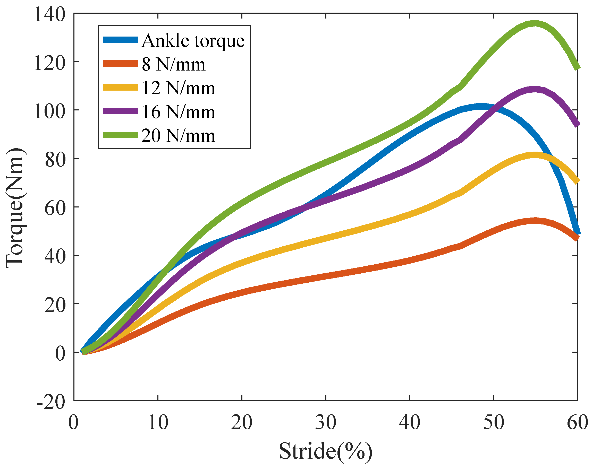
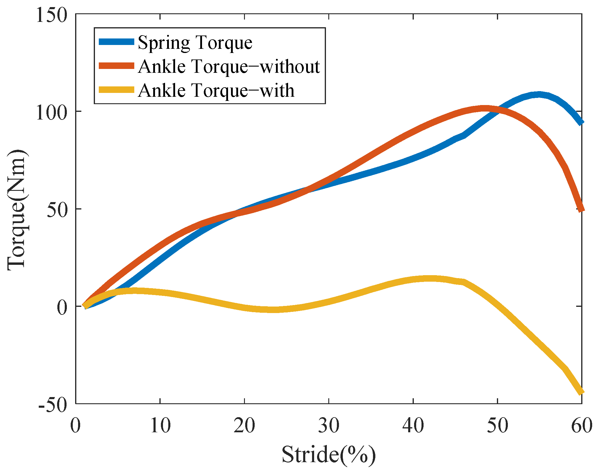
2.4. The Simulation of Body–Exoskeleton Interaction Force

Based on the principal analysis of the body–exoskeleton interaction force, we proposed using elastic elements combined with the characteristics of human gait to reduce the output of human power during walking with the passive exoskeleton. Here, according to Formula (4) and the clinical gait data [38], we could obtain the ankle torque of the passive exoskeleton and the spring torque for different exoskeleton spring stiffnesses; the results are shown in Figure 5.
In Figure 5, the ankle torque of the passive exoskeleton was obtained under walking with 30 kg. The approximate spring constant could be calculated from the relationship between spring torque angle and ankle torque in the torque analysis result. The spring constant of the spring used for this mechanism could be easily calculated; consequently, the spring constant of the ankle module was determined to be 16 N/mm. Under this condition, the results of comparing and analyzing the changes in the body–exoskeleton interaction force are shown in Figure 6.
During the passive exoskeleton walking with load, the movement of the exoskeleton ankle in the stance phase was maintained by the load torque, spring torque and the driving torque of the human. In Figure 6, using the heel touching the ground as the starting point of a gait cycle, the deformation of the spring and its torque increased. Because the spring torque offset part of the load torque, the required ankle torque decreased, which reduced the burden of the driving force of the human ankle. At the end of the stance phase, the elastic potential energy stored by the spring assisted the ankle plantar flexion and reduced the propulsion of the human ankle. Using the simulation results in Figure 6, the body–exoskeleton interaction force under the action of the spring reduced by 98.5% with spring compared to without spring, which preliminarily verified the effectiveness of this mode in theory.

3. The Design of Exoskeleton Prototype and Experiments

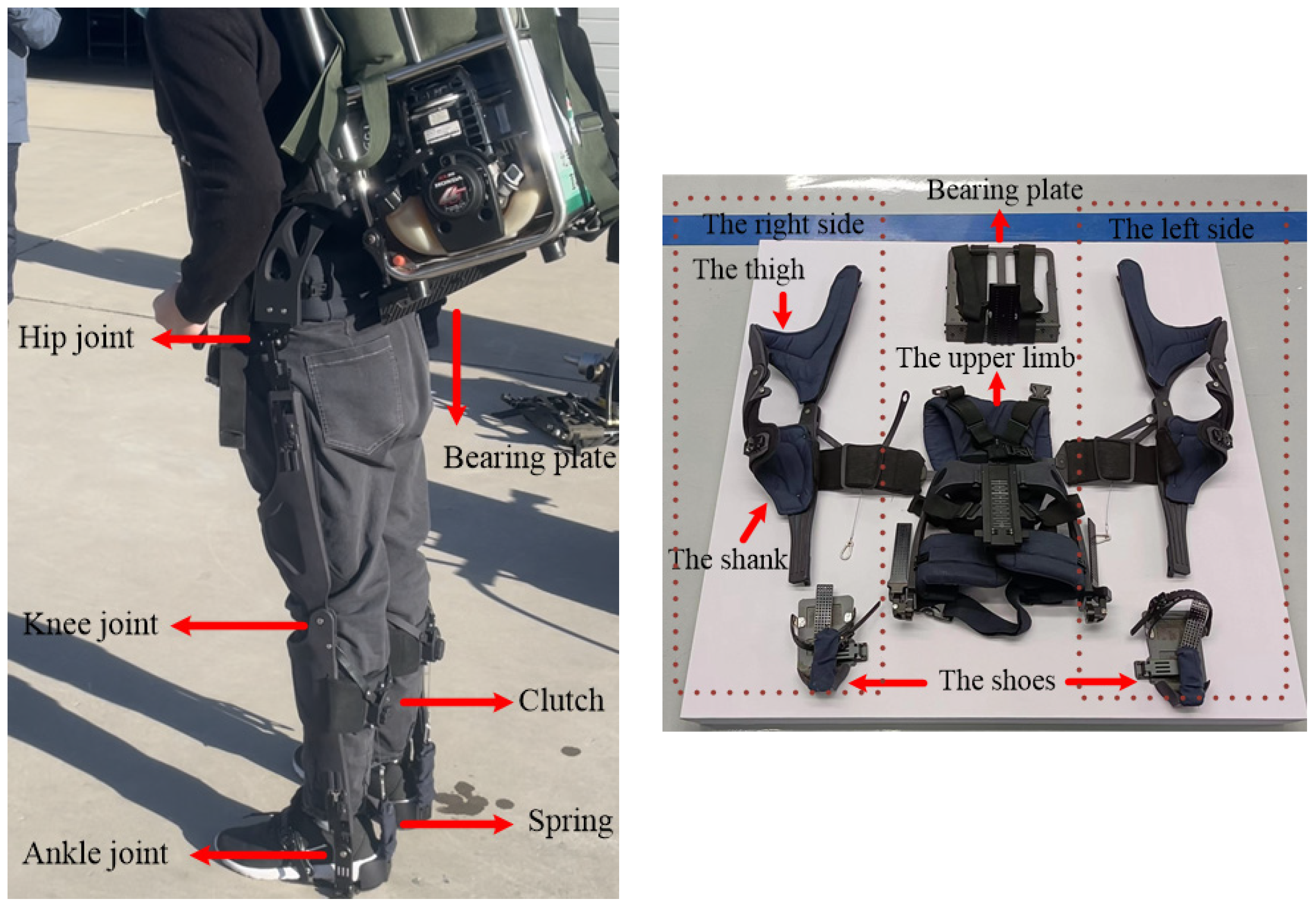
3.1. The Design of the Exoskeleton
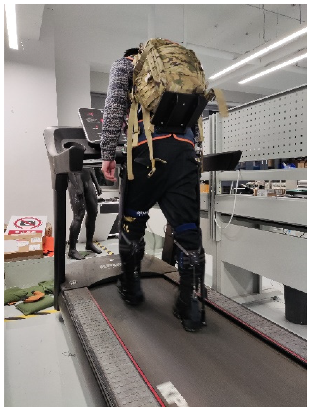
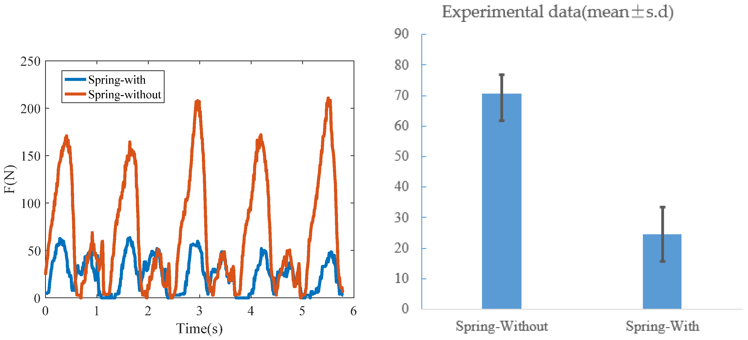
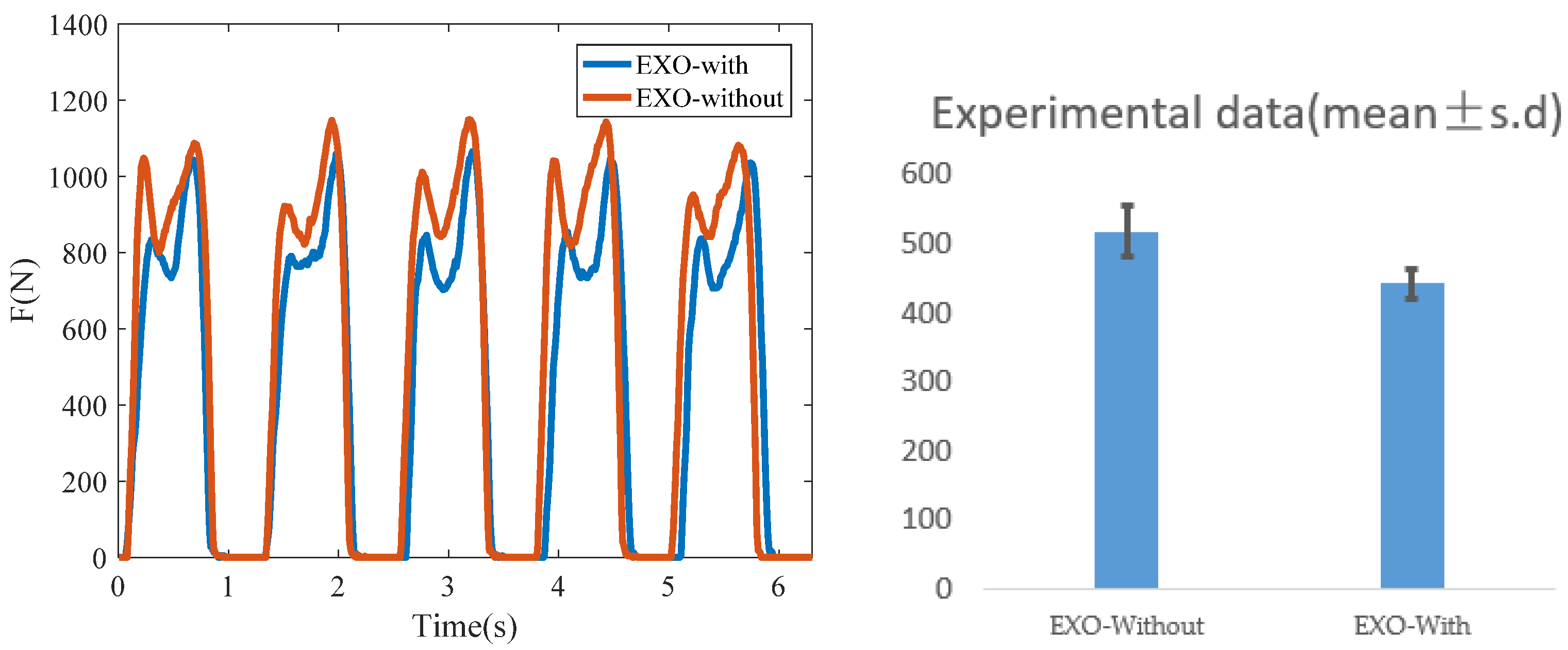
The proposed exoskeleton in this paper has a load-bearing plate, a complete lower exoskeleton and a ground support structure that was convenient for the bearing of loads, as shown in Figure 7. In the sagittal plane, each leg of the exoskeleton system was designed with three DOFs for the hip, one for the knee and two for the ankle; the DOFs of the hip, knee and ankle were closely related to human gait. The ankle joint of the exoskeleton was embedded with a spring, which generated a driving force according to the deformation of the spring. Considering that the movement range of the human limb joint was small during normal walking, the exoskeleton joint in this paper was set as a single hinge, and the body–exoskeleton connections were composed of soft binding and no redundant DOFs were added. On the back of the exoskeleton leg, we designed a clutch to control the state of the spring so that we could adjust the initial length of the spring, that is, the spring could be adjusted to the state of tension or relaxation.
In Figure 7, the modules of the prototype are shown. The bearing plate was located in the back of the human trunk, which was mainly made of carbon fiber material with light weight and high strength. It was connected with the upper limb of the exoskeleton and fixed with the human trunk through the exoskeleton shoulder belt. The exoskeleton upper limbs connected the left and right leg structures. Among them, the leg structures obtained the properties of mirror symmetry and could be well pasted with the lower limbs of the human body. The soft cushion was attached inside the leg structures, which could improve the wearing comfort. The leg structures were finally connected with the exoskeleton shoes, and the load weight was transmitted to the ground.

3.2. Experiment

Based on the simulation results, the body–exoskeleton interaction force was significantly improved by our own design. However, it was affected by the matching degree between exoskeleton and wearer, load size, walking speed and other factors in practice. In order to test the actual effect of improving the body–exoskeleton interaction force, this paper completed the test experiment of seven wearers (N = 7; age = 26.5 ± 0.98 years; mass = 78.3 ± 1.6 kg; height = 1.75 ± 0.138 m) walking with the exoskeleton and carrying a weight of 30 kg at 4 km/h walking speed on a treadmill (See Figure 8). In order to obtain the body–exoskeleton interaction force and plantar pressure data of the tester, we used the Pedar-x (a wireless plantar pressure test device, Novel, Munich, Germany) to get these experimental data. The experiment was approved by the Ethics Committee of Beijing institute of technology (BIT-EC-H-2021118).
Each experimenter completed two sets of tests. For the first set of tests, the spring of the exoskeleton was relaxed when the wearer walked with the passive exoskeleton; for the second set of tests, the spring of the exoskeleton was tensioned when the wearer walked with the passive exoskeleton. The test indicators were the body–exoskeleton interaction force at the lower leg of human body and the plantar pressure.
In order to ensure the reliability of the test data, each walking experiment lasted for 5 min so that there were sufficient experimental data in each test. According to the collected experimental data, the actual effect of the body–exoskeleton interaction force in the lower leg of the exoskeleton could be obtained. The results were as follows.
It can be seen from Figure 9 that the body–exoskeleton interaction force changed periodically, and its difference in amplitude value between the two states verified the effectiveness of the operation mechanism of the exoskeleton. When the spring of the exoskeleton ankle was locked, the average value of the body–exoskeleton interaction force was 24.63 N, and the peak value reached 63.54 N; when the spring of the exoskeleton ankle was in a relaxed state, the average value of the interaction force was 70.55 N, and the peak value reached 210.8 N. By comparison, when the spring of the exoskeleton ankle was locked, the average value of body–exoskeleton interaction force decreased by 65.1%, while its peak value decreased by 69.9% compared with no spring in the exoskeleton ankle.
In Figure 10, when the spring was locked, the average value of plantar pressure was 442.24 N and its peak value was 1066 N; when the spring was in a relaxed state, the average plantar pressure was 518.66 N and its peak value was 1149 N. The results show that when the wearer is walking with the exoskeleton, its plantar pressure was affected by the spring tension. When the spring was relaxed, there was no force on the exoskeleton leg and shoes; however, when the spring was locked, there was a radial tension on the shoes and lower leg of the exoskeleton, which resulted in the reduction in plantar pressure of the human. The difference in plantar pressure of the human between the two states was the spring tension, and its value was 76.42 N, accounting for 14.7% of the human plantar pressure. It can be seen that the plantar pressure of the human body was enough to stretch the spring of the exoskeleton.

3.3. Discussion

During the development of the exoskeleton robot, if the active drive was added to the exoskeleton robot at the beginning of the design, its system weight and battery life would restrict its use [39]. In contrast, the passive exoskeleton was not limited by these factors, but the defects of the passive exoskeleton were also analyzed in Section 2, which needed the human body to provide the driving force for its movement. In order to improve this situation, the common method was that the elastic elements were embedded in the passive exoskeleton to assist the movement of human joints [19]. Based on the analysis of the dynamic model of the body–exoskeleton coupling system, this paper proposed that using the spring to connect the two independent gravity systems improves the stability of the exoskeleton and reduces the output of human power.
Compared with the current literature, one of the ways to reduce the negative force between the human body and exoskeleton was increasing the DOFs in the body–exoskeleton connection [7] to avoid harm to the human body. However, the normal operation of the passive exoskeleton required the wearer to provide all the power, which bore the brunt of the design of the passive exoskeleton. One of the novelties of this paper was that the spring was used to realize the local self-stabilization of the exoskeleton robot and finally assist human movement to reduce the output of human power. Considering the joints’ torque varied with the load [40], we obtained the joint torque when the exoskeleton was loaded with 30 kg, and on the basis of the results we acquired the spring stiffness according to the design of the exoskeleton, which was closest to the real situation.
On the basis of the operation principle of the body–exoskeleton system, we designed the corresponding exoskeleton robot, and completed the effect verification test. The results show that the interaction force was significantly reduced, which verified our analysis of the body–exoskeleton system. The optimal design of the passive exoskeleton was in the calf of the exoskeleton, according to the research on the transfer of driving force in the literature [41,42]; the design idea of the exoskeleton in this paper could be extended to the knee and hip joint to reduce the interaction force. This part of the work would be completed in future research.

4. Conclusions

In this paper, we studied the body–exoskeleton coupling mechanism during human walking with an exoskeleton and carrying load. Through the analysis of the body–exoskeleton coupling dynamics, we established the mathematical model of the redistribution of the body–exoskeleton interaction force, preliminarily realized the combination of human gravity and load weight, and verified its effectiveness through simulation. On this basis, we designed the corresponding exoskeleton robot and completed the comparative experiment. The results showed that the exoskeleton robot effectively reduced the interaction force. The modelling and design method could also be naturally extended to other human joints with exoskeletal assistance, which might enrich the understanding of the interaction transfer mechanisms between joints and the inspiration for motivating the engineering design of wearable devices.

Author Contributions

Conceptualization, N.Z. and Q.S.; methodology, N.Z.; software, D.W.; validation, Y.L.; formal analysis, Q.S.; investigation, N.Z.; resources, N.Z.; data curation, D.W.; writing—original draft preparation, N.Z.; writing—review and editing, N.Z.; visualization, Y.L.; supervision, Y.L.; project administration, Y.L.; funding acquisition, Y.L. All authors have read and agreed to the published version of the manuscript.

Funding

This work was supported in part by the Ministry of Science and Technology national key RD program (Grant Number: 2017YFB1300500), in part by the National Natural Science Foundation of China (Grant No.51905035), and in part by the Science and Technology Innovation Special Zone Youth Project (Grant No. 2016312ZT00200203), and in part by the Science and Technology In-novation Special Zone Project (Grant No. 2116312ZT00200202).

Institutional Review Board Statement

Our experiment was approved by the Ethics Committee of Beijing institute of technology (BIT-EC-H-2021118).

Informed Consent Statement

Informed consent was obtained from all subjects involved in the study.

Data Availability Statement

The data that support the findings of this study are available from the corresponding author upon reasonable request.

Conflicts of Interest

The authors declare no conflict of interest.

References

  1. De Looze, M.P.; Bosch, T.; Krause, F.; Stadler, K.S.; O’Sullivan, L. Exoskeletons for industrial application and their potential effects on physical work load. Ergonomics 2016, 59, 671–681. [Google Scholar] [CrossRef] [PubMed] [Green Version]
  2. Zoss, A.B.; Kazerooni, H.; Chu, A. Biomechanical design of the Berkeley lower extremity exoskeleton (BLEEX). IEEE/ASME Trans. Mechatron. 2006, 11, 128–138. [Google Scholar] [CrossRef]
  3. Mihelj, M.; Nef, T.; Riener, R. ARMin II-7 DoF rehabilitation robot: Mechanics and kinematics. In Proceedings of the 2007 IEEE International Conference on Robotics and Automation, Rome, Italy, 10–14 April 2007; pp. 4120–4125. [Google Scholar]
  4. Kim, S.; Nussbauma, M.A.; Esfahania, M.I.M.; Alemi, M.M.; Jia, B.; Rashedi, E. Assessing the influence of a passive, upper extremity exoskeletal vest for tasks requiring arm elevation: Part I—“Expected” effects on discomfort, shoulder muscle activity, and work task performance. Appl. Ergon. 2018, 70, 315–322. [Google Scholar] [CrossRef] [PubMed]
  5. Yan, T.; Cempini, M.; Oddo, C.M.; Vitiello, N. Review of assistive strategies in powered lower-limb orthoses and exoskele-tons. Robot. Auton. Syst. 2015, 64, 120–136. [Google Scholar] [CrossRef]
  6. Giovacchini, F.; Vannetti, F.; Fantozzi, M.; Cempini, M.; Cortese, M.; Parri, A.; Yan, T.; Lefeber, D.; Vitiello, N. A light-weight active orthosis for hip movement assistance. Robot. Auton. Syst. 2015, 73, 123–134. [Google Scholar] [CrossRef]
  7. Li, J.; Zuo, S.; Xu, C.; Zhang, L.; Dong, M.; Tao, C.; Ji, R. Influence of a Compatible Design on Physical Human-Robot Interaction Force: A Case Study of a Self-Adapting Lower-Limb Exoskeleton Mechanism. J. Intell. Robot. Syst. 2019, 98, 525–538. [Google Scholar] [CrossRef]
  8. Jarrasse, N.; Morel, G. Connecting a Human Limb to an Exoskeleton. IEEE Trans. Robot. 2012, 28, 697–709. [Google Scholar] [CrossRef] [Green Version]
  9. Leboucher, J.; Lempereur, M.; Burdin, V.; Remy-Neris, O. Radius movement simulation based on articular surfaces. In Proceedings of the International Conference on Computational Systems-Biology and Bioinformatics, Bangkok, Thailand, 3–5 November 2010. [Google Scholar]
  10. Lee, S.; Kim, J.; Baker, L.; Long, A.; Karavas, N.; Menard, N.; Galiana, I.; Walsh, C.J. Autonomous multi-joint soft exosuit with augmentation-power-based control parameter tuning reduces energy cost of loaded walking. J. Neuroeng. Rehabil. 2018, 15, 66. [Google Scholar] [CrossRef]
  11. Ding, Y.; Galiana, I.; Asbeck, A.T.; De Rossi, S.M.M.; Bae, J.; Santos, T.R.T.; De Araujo, V.L.; Lee, S.; Holt, K.G.; Walsh, C. Biomechanical and Physiological Evaluation of Multi-Joint Assistance with Soft Exosuits. IEEE Trans. Neural Syst. Rehabil. Eng. 2017, 25, 119–130. [Google Scholar] [CrossRef]
  12. Pérez Vidal, A.F.; Rumbo Morales, J.Y.; Ortiz Torres, G.; Sorcia Vázquez, F.d.J.; Cruz Rojas, A.; Brizuela Mendoza, J.A.; Rodríguez Cerda, J.C. Soft Exoskeletons: Development, Requirements, and Challenges of the Last Decade. Actuators 2021, 10, 166. [Google Scholar] [CrossRef]
  13. Schiele, A. An ex-plicit model to predict and interpret constraint force creation in pHRI with exoskeletons. In Proceedings of the 2008 IEEE International Conference on Robotics and Automation, Pasadena, CA, USA, 19–23 May 2008; pp. 1324–1330. [Google Scholar]
  14. Lamoreux, L.W. Kinematic measurements in the study of human walking. Bull. Prosthet. Res. 1971, 10, 3–84. [Google Scholar] [PubMed]
  15. Markolf, K.L.; Mensch, J.S.; Amstutz, H.C. Stiffness and laxity of the knee-The contributions of the supporting structures, a quantitative in vitro study. J. Bone Jt. Surg. Amer. 1976, 58, 583–594. [Google Scholar] [CrossRef]
  16. Olivier, J.; Bouri, M.; Ortlieb, A.; Bleuler, H.; Clavel, R. Development of an assistive motorized hip orthosis: Kinematics analysis and mechanical design. IEEE Int. Conf. Rehabil. Robot. 2013, 2013, 6650495. [Google Scholar] [PubMed]
  17. Sergi, F.; Accoto, D.; Tagliamonte, N.L.; Carpino, G.; Pathiyil, L.; Guglielmelli, E. A systematic graph-based method for the kinematic synthesis of non-anthropomorphic wearable robots for the lower limbs. In Proceedings of the 2010 IEEE Conference on Robotics, Automation and Mechatronics, Singapore, 28–30 June 2010; pp. 100–105. [Google Scholar]
  18. Banala, S.K.; Kim, S.H.; Agrawal, S.K.; Scholz, J.P. Robot assisted gait training with active leg exoskeleton (ALEX). IEEE Trans. Neural Syst. Rehabil. 2009, 17, 2–8. [Google Scholar] [CrossRef] [PubMed]
  19. Walsh, C.J.; Endo, K.; Herr, H. A quasi-passive leg exoskeleton for load-carrying augmentation. Int. J. Hum. Robot. 2007, 4, 487–506. [Google Scholar] [CrossRef]
  20. Schiele, A.; van der Helmb, F.C.T. Influence of attachment pressure and kinematic configuration on pHRI with wearable robots. Appl. Bionics Biomech. 2009, 6, 157–173. [Google Scholar] [CrossRef] [Green Version]
  21. Jarrasse, N.; Tagliabue, M.; Robertson, J.V.G.; Maiza, A.; Crocher, V.; Roby-Brami, A.; Morel, G. A Methodology to Quantify Alterations in Human Upper Limb Movement During Co-Manipulation with an Exoskeleton. IEEE Trans. Neural Syst. Rehabil. 2010, 18, 389–397. [Google Scholar] [CrossRef] [Green Version]
  22. Zoss, A.; Kazerooni, H.; Chu, A. On the mechanical design of the Berkeley Lower Extremity Exoskeleton (BLEEX). In Proceedings of the IEEE International Conference on Intelligent Robots and Systems, Edmonton, AB, Canada, 2–6 August 2005; pp. 3465–3472. [Google Scholar]
  23. Kawamoto, H.; Sankai, Y. Power assist method based on Phase Sequence and muscle force condition for HAL. Adv. Robot. 2005, 19, 717–734. [Google Scholar] [CrossRef]
  24. Qi, Z.; Liu, Y.; Song, Q.; Zhou, N. An Improved Greedy Reduction Algorithm Based on Neighborhood Rough Set Model for Sensors Screening of Exoskeleton. IEEE Sens. J. 2021, 21, 26964–26977. [Google Scholar] [CrossRef]
  25. Gao, F.; Pan, D. Mechanical Design of a Hybrid Leg Exoskeleton to Augment Load-Carrying for Walking. Int. J. Adv. Robot. Syst. 2013, 10, 395. [Google Scholar]
  26. Yu, S.; Lee, H.; Kim, W.; Han, C. Development of an underactuated exoskeleton for effective walking and load-carrying assist. Adv. Robot. 2016, 30, 535–551. [Google Scholar] [CrossRef]
  27. Chen, S.; Han, T.; Dong, F.; Lu, L.; Liu, H.; Tian, X.; Han, J. Precision Interaction Force Control of an Underactuated Hydraulic Stance Leg Exoskeleton Considering the Constraint from the Wearer. Machines 2021, 9, 96. [Google Scholar] [CrossRef]
  28. Zhou, X.; Liu, G.; Han, B.; Wu, L.; Li, H. Design of a Human Lower Limbs Exoskeleton for Biomechanical Energy Harvesting and Assist Walking. Energy Technol. 2020, 9, 2000726. [Google Scholar] [CrossRef]
  29. Capitani, S.L.; Bianchi, M.; Secciani, N.; Pagliai, M.; Meli, E.; Ridolfi, A. Model-based mechanical design of a passive lower-limb exoskele-ton for assisting workers in shotcrete projection. Meccanica 2021, 56, 195–210. [Google Scholar] [CrossRef]
  30. Yan, Z.; Han, B.; Du, Z.; Huang, T.; Bai, O.; Peng, A. Development and testing of a wearable passive lower-limb support exoskeleton to support industrial workers. Biocybern. Biomed. Eng. 2021, 41, 221–238. [Google Scholar] [CrossRef]
  31. Zhou, N.; Liu, Y.; Song, Q.; Qi, Z.; Ren, W.; Zhang, K. Analysis, design and preliminary evaluation of an anthropometric self-stabilization passive exoskeleton for enhancing the ability of walking with loads. Robot. Auton. Syst. 2022, 153, 09218890. [Google Scholar] [CrossRef]
  32. Hidayah, R.; Sui, D.; Wade, K.A.; Chang, B.-C.; Agrawal, S. Passive knee exoskeletons in functional tasks: Biomechanical effects of a SpringExo coil-spring on squats. Wearable Technol. 2021, 2, e7. [Google Scholar] [CrossRef]
  33. Karfidova, A.O.; Vasilyev, M.V.; Morozova, I.G. Modernization of an industrial passive exoskeleton prototype for lower ex-tremities using rapid prototyping technologies. Mater. Sci. Eng. 2020, 971, 052049. [Google Scholar]
  34. Rajagopal, A.; Dembia, C.; DeMers, M.; Delp, D.D.; Hicks, J.L.; Delp, S.L. Full-Body Musculoskeletal Model for Muscle-Driven Simulation of Human Gait. IEEE Trans. Biomed. Eng. 2016, 63, 2068–2079. [Google Scholar] [CrossRef]
  35. Wang, H. Anatomy of the Human System; Fudan University Press: Shanghai, China, 2008. [Google Scholar]
  36. Celebi, B.; Yalcin, M.; Patoglu, V. Assist ON-Knee: A self-aligning knee exoskeleton. In Proceedings of the IEEE/RSJ International Conference on Intelligent Robots and Systems, Tokyo, Japan, 3–7 November 2013. [Google Scholar]
  37. Xie, Q.; Meng, Q.; Zeng, Q.; Fan, Y.; Dai, Y.; Yu, H. Human-Exoskeleton Coupling Dynamics of a Multi-Mode Therapeu-tic Exoskeleton for Upper Limb Rehabilitation Training. IEEE Access 2021, 9, 61998–62007. [Google Scholar] [CrossRef]
  38. Kirtley, C. CGA Normative Gait Database; Hong Kong Polytechnic University: Hong Kong, China, 2005. [Google Scholar]
  39. Chen, B.; Zi, B.; Zeng, Y.; Qin, L.; Liao, W.-H. Ankle-foot orthoses for rehabilitation and reducing metabolic cost of walking: Possi-bilities and challenges. Mechatronics 2018, 53, 241–250. [Google Scholar] [CrossRef]
  40. Han, Y.; Wang, X. The biomechanical study of lower limb during human walking. Sci. China Technol. Sci. 2011, 54, 983–991. [Google Scholar] [CrossRef]
  41. Panizzolo, F.A.; Galiana, I.; Asbeck, A.T.; Siviy, C.; Schmidt, K.; Holt, K.G.; Walsh, C.J. A biologically-inspired multi-joint soft exosuit that can reduce the energy cost of loaded walking. J. Neuroeng. Rehabil. 2016, 13, 43. [Google Scholar] [CrossRef] [PubMed] [Green Version]
  42. van Dijk, W.; van der Kooij, H.; Hekman, E. A Passive Exoskeleton with Artificial Tendons: Design and experimental evaluation. IEEE Int. Conf. Rehabil. Robot. 2011, 2011, 5975470. [Google Scholar]
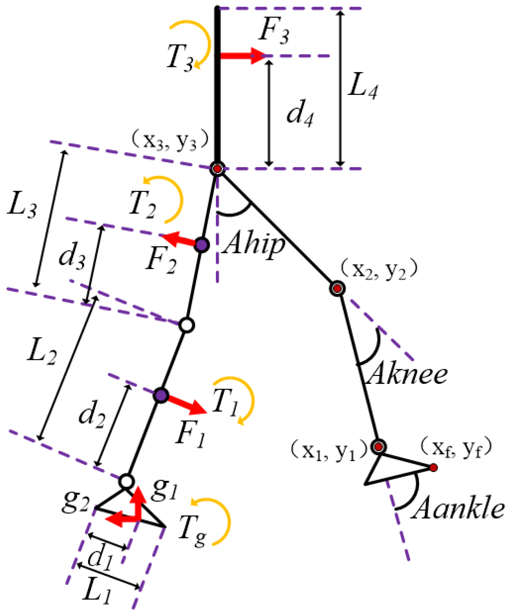
Figure 1. The human gait. The dotted line represents the left leg in the swing state, the solid line represents the right leg in the stance phase.
Machines 10 00371 g001
Figure 2. Human main movement (left) and the body–exoskeleton integrated model (right). In the right figure, the red solid line represents the exoskeleton robot, the green solid line represents the human body, the black dotted line represents the body–exoskeleton connected point, the circle represents a rotational DOF, the combination of circle and semi-circle represents the ball joint, and the purple square represents the trunk.
Machines 10 00371 g002
Figure 3. Simplified model of exoskeleton.
Machines 10 00371 g003
Figure 4. The redistribution of body–exoskeleton interaction force.   G l represents the weight of load, G h represents the gravity of human body, F s and F s represent the force of the elastic element.
Machines 10 00371 g004
Figure 5. The results of ankle torque of the exoskeleton and the torque generated by the spring over a walking stride from heel strike (0%) to heel strike (60%) for different exoskeleton spring stiffnesses. The blue line represents the ankle torque, the lines of other colors represent the torque of the spring at appropriate spring stiffnesses.
Machines 10 00371 g005
Figure 6. The results of ankle torque of the exoskeleton. Spring torque represents the torque of the spring at the back of the lower leg; ankle torque–without represents the torque of the exoskeleton ankle when the spring was relaxed, and ankle torque–with represents the torque of the exoskeleton ankle when the spring was locked.
Machines 10 00371 g006
Figure 7. The exoskeleton prototype.
Machines 10 00371 g007
Figure 8. The exoskeleton experiment.
Machines 10 00371 g008
Figure 9. The body–exoskeleton interaction force and the mean ± s.d. Spring–with represents when the spring of the exoskeleton was locked, and spring–without represents when the spring of the exoskeleton was in a relaxed state.
Machines 10 00371 g009
Figure 10. The results of the plantar pressure test and the mean ± s.d. EXO–with means the spring of exoskeleton ankle was locked, and EXO–without means the spring of exoskeleton ankle was relaxed.
Machines 10 00371 g010
Table 1. The meaning of the symbols in Figure 3.
SymbolMeaning
Li, i = 1,2,3,4Length of each connecting rod
di, i = 1,2,3,4The distance from the center of mass of each link to the corresponding joint
Ahip, Aknee, AankleThe angle of each connecting rod to the corresponding rod
F1, F2, F3Human–machine interaction force
T1, T2, T3Human–machine interaction torque
(xi,yi), i = 1,2,3Joint coordinates of exoskeleton
TgGround reaction torque
g1g2Ground reaction force
Publisher’s Note: MDPI stays neutral with regard to jurisdictional claims in published maps and institutional affiliations.

