
Buffering Performance Analysis of an Ostrich-like Leg Based on a Seven-Link Parallel Mechanism

 ,
, 
Abstract
:1. Introduction
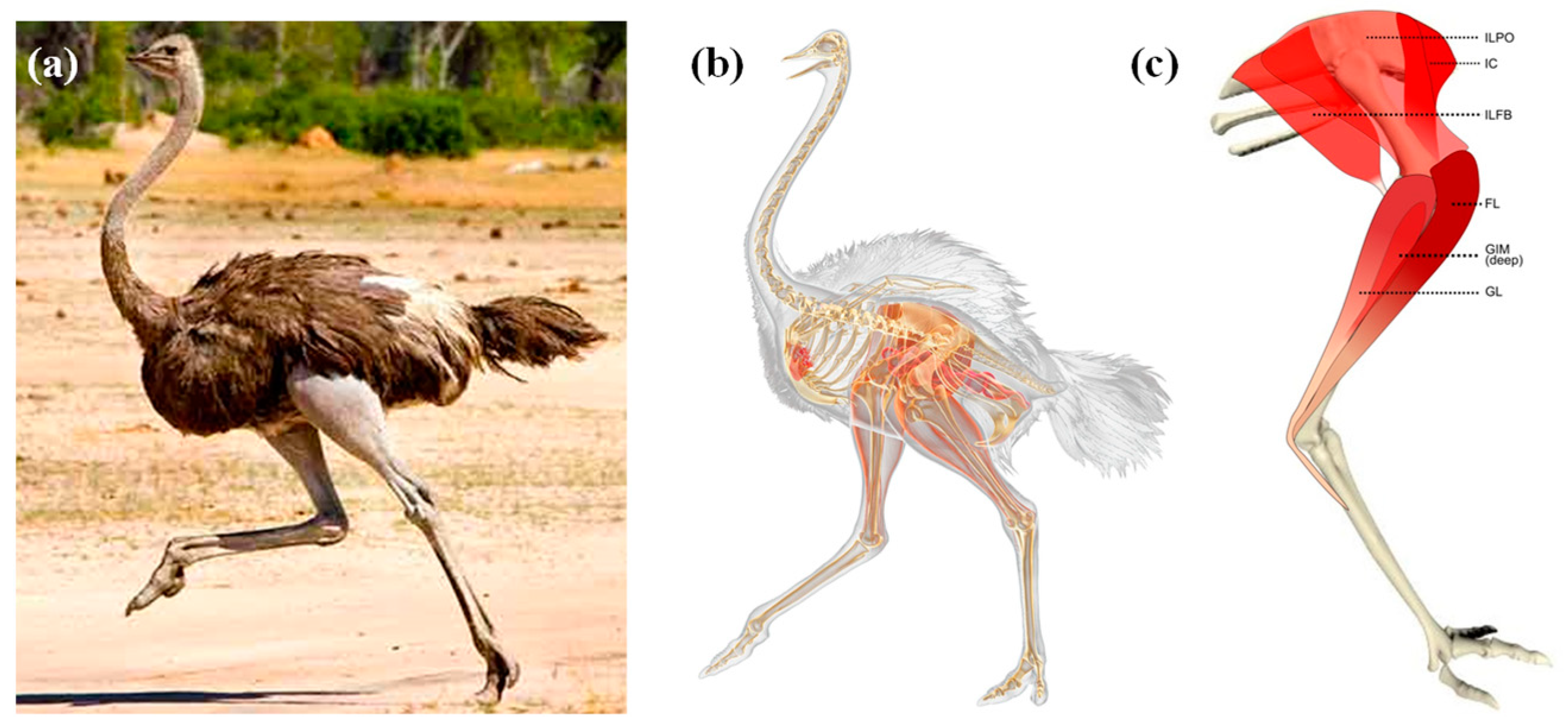
2. Structural Analysis of Ostrich Leg
3. Structural Characteristics of Bionic Legs
3.1. Influencing Factors of Equivalent Elastic Modulus of the Ostrich-like Leg
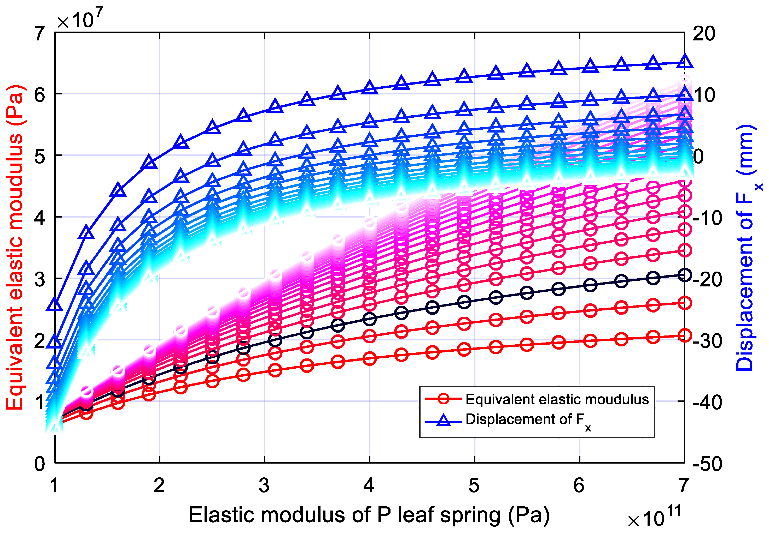
3.2. Influence of Ep, Eq on the and Fx of the Ostrich-like Leg
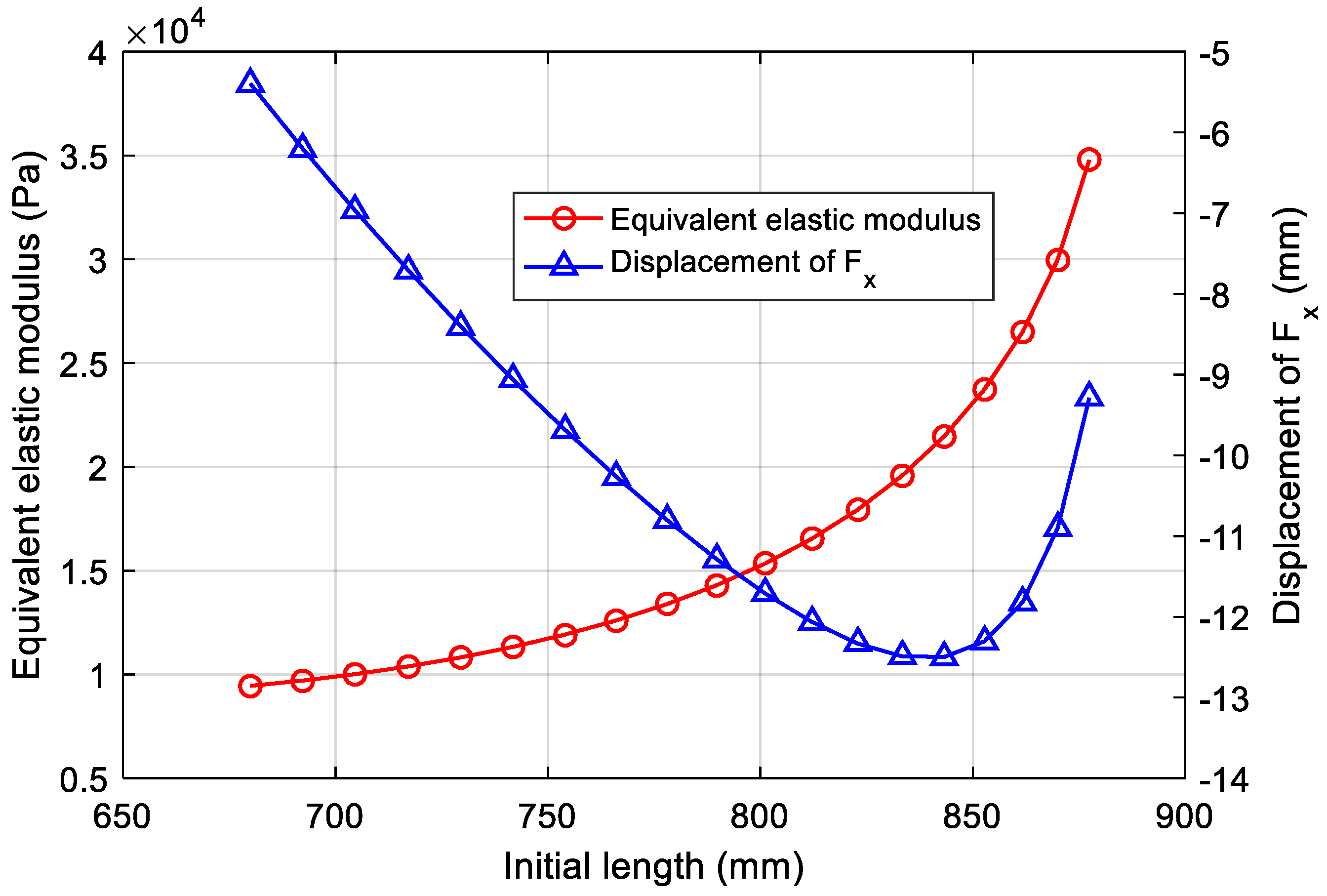
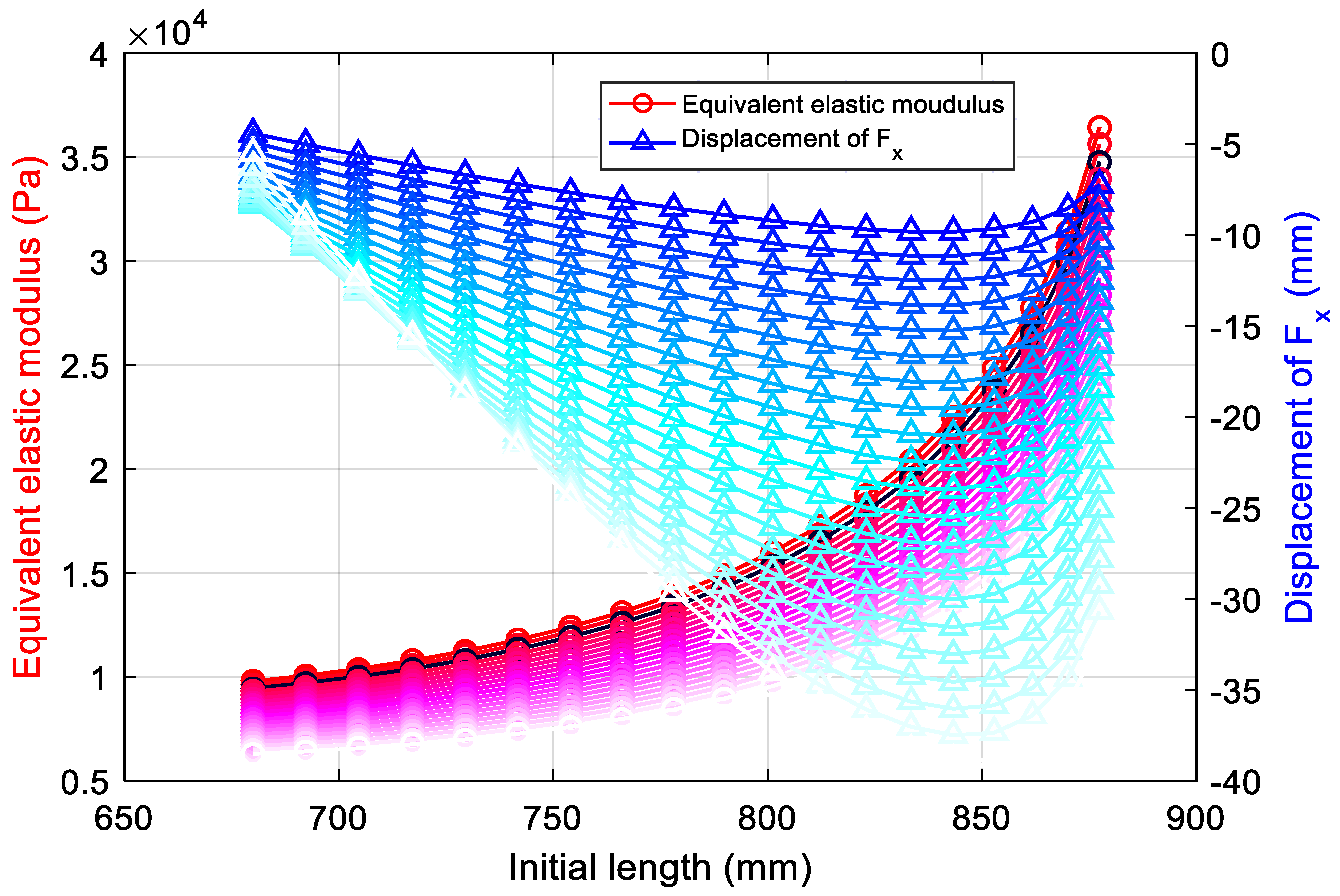
3.3. Influence of Initial Length to of the Ostrich-like Leg
4. Buffering Characteristics of the Bionic Leg
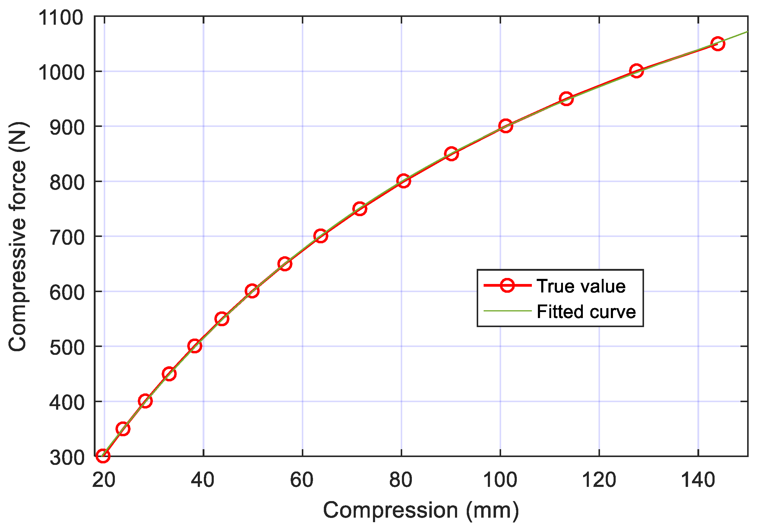
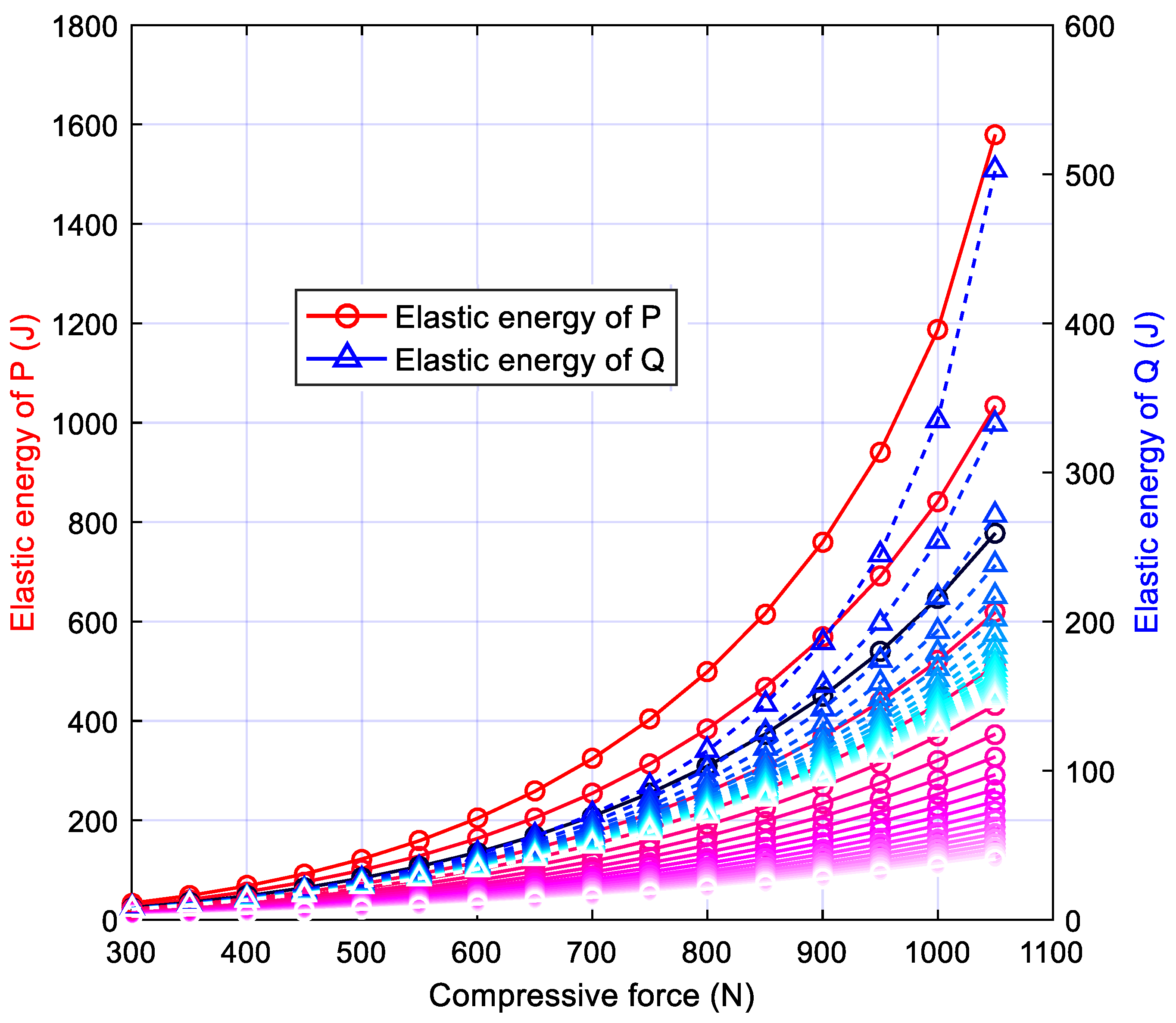
4.1. The Energy Storage of the Leaf Spring
4.2. Buffering Model Prediction
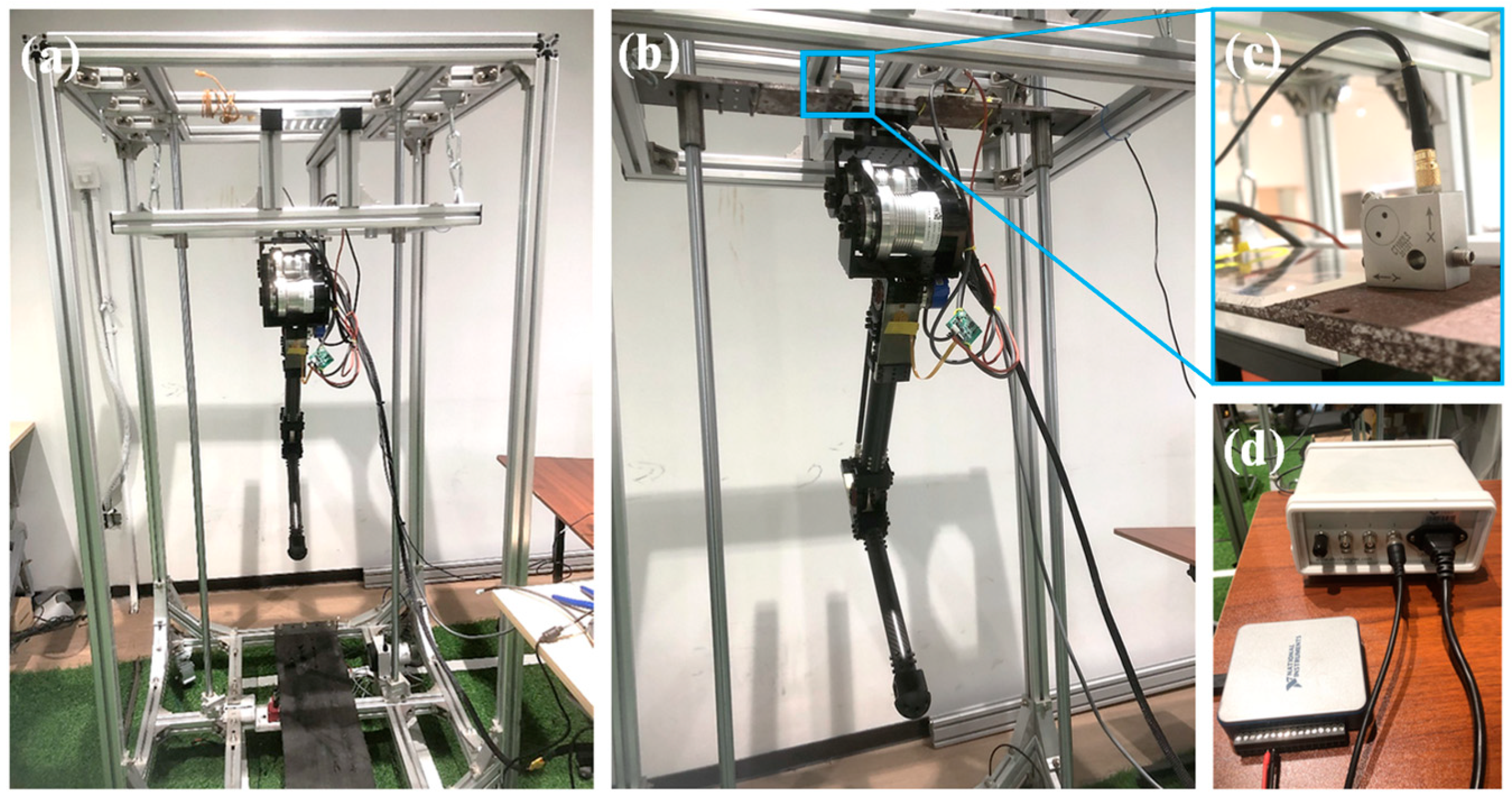
5. Experimental Process and Analysis
6. Prospect
7. Conclusions
- 1.
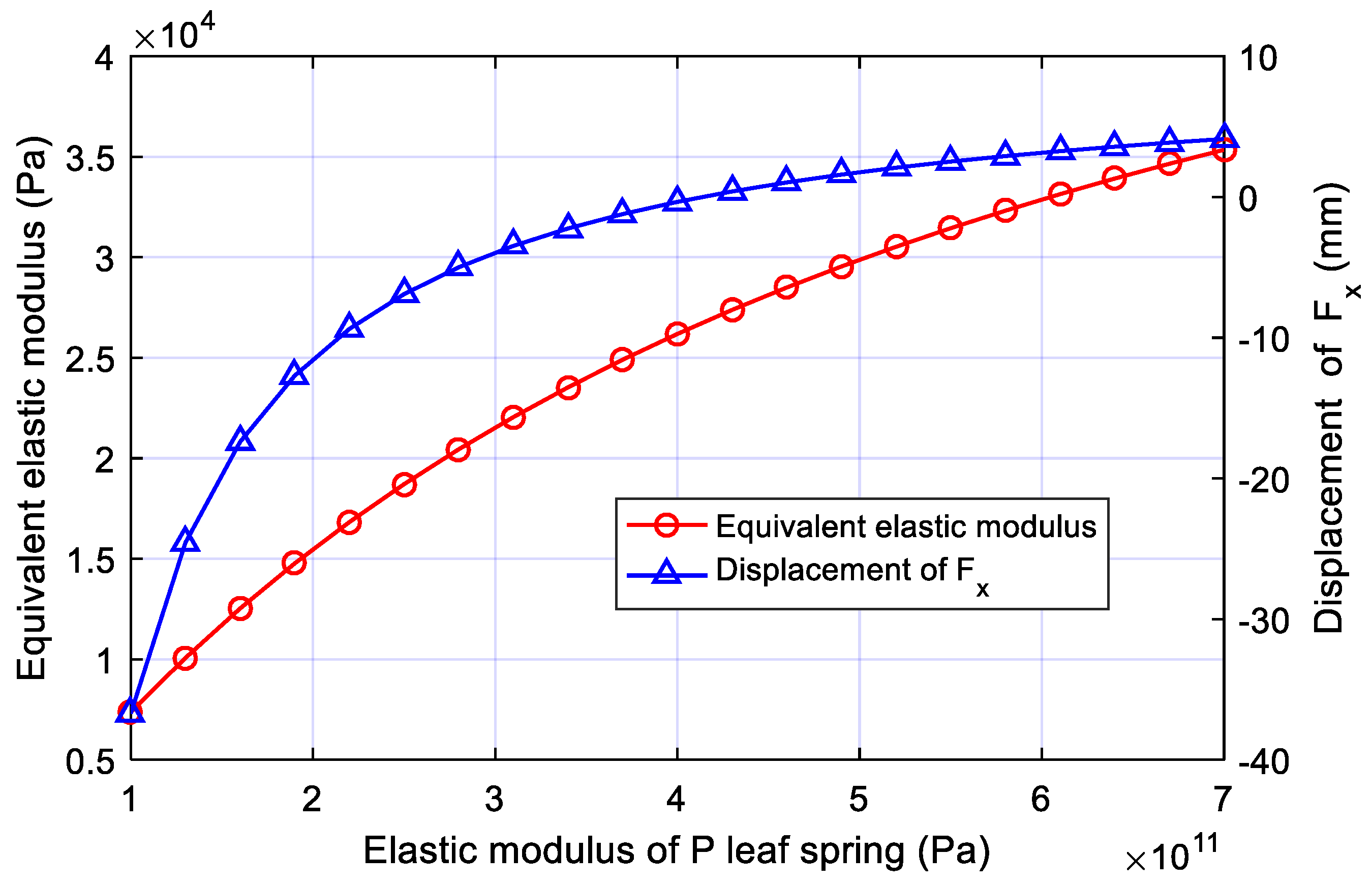
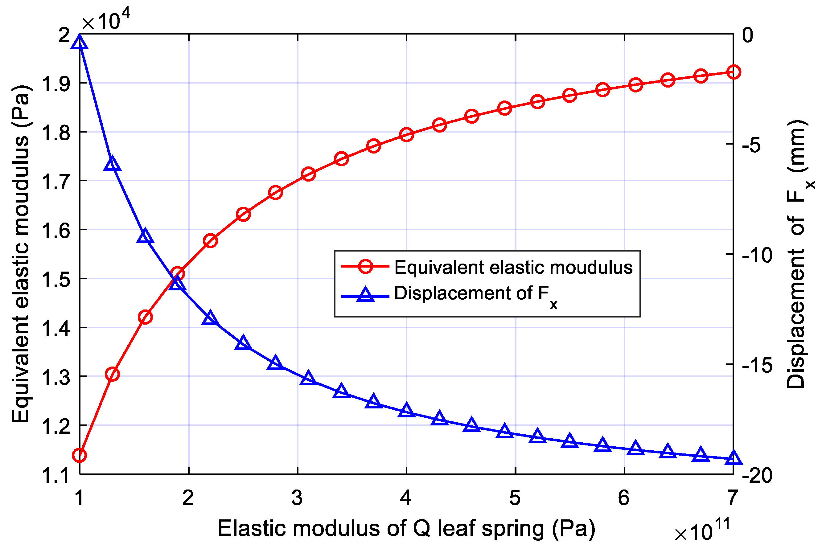
- For a single leg with an initial length of 800.9 mm and a compressive force of 300 N, the equivalent elastic modulus of the structure () and the displacement of point F in the x-direction (Fx) also increases with the increase of the elastic moduli of the P and Q leaf springs, and the rate of change decreases with the elastic moduli of the leaf springs.
- 2.
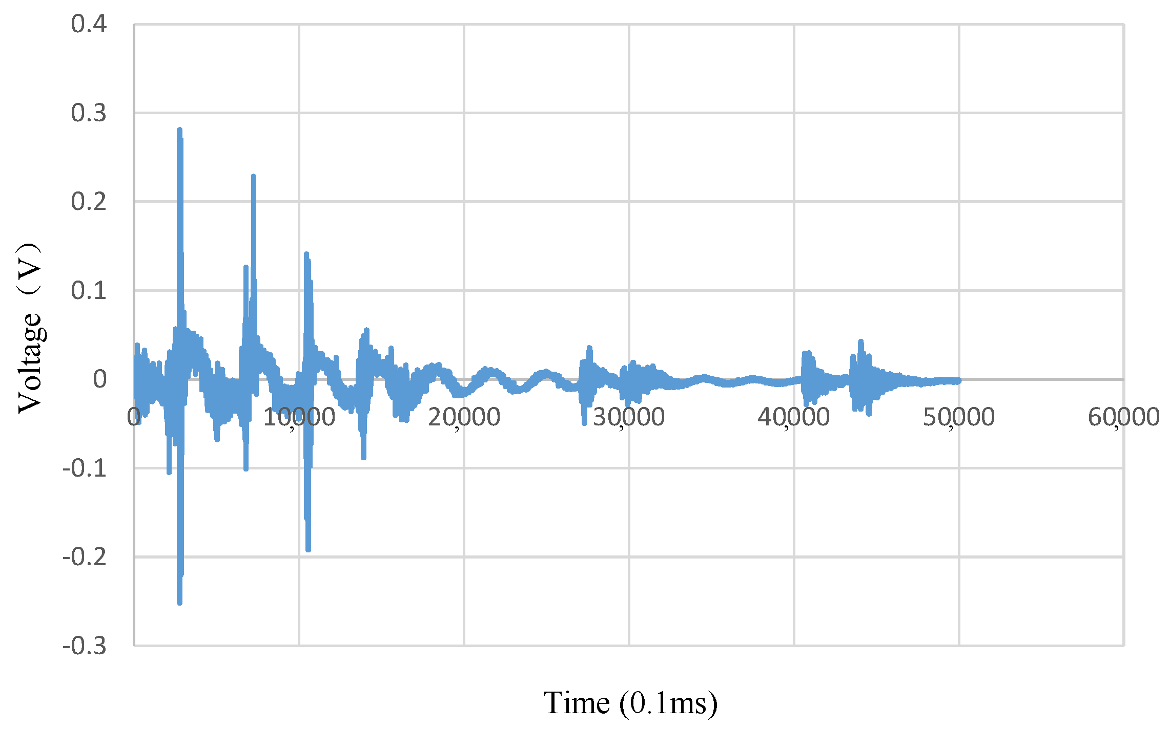
- Compared with the ~1000 Hz impact wave frequency of the rigid body, the frequency of this leg is about 3 Hz, indicating that the structure has good buffering performance.
- 3.
- The initial height of the bionic leg has a significant impact on the equivalent elastic modulus of the structure and the movement stability of the robot in the horizontal plane. When the initial height is about 850 mm, the stability of the robot is the best.
- 4.
- The calculation result of impact acceleration by the kinematic model is close to the measured one, and the error is due to the connection mode and the complex stress form of the leaf spring.
- 5.
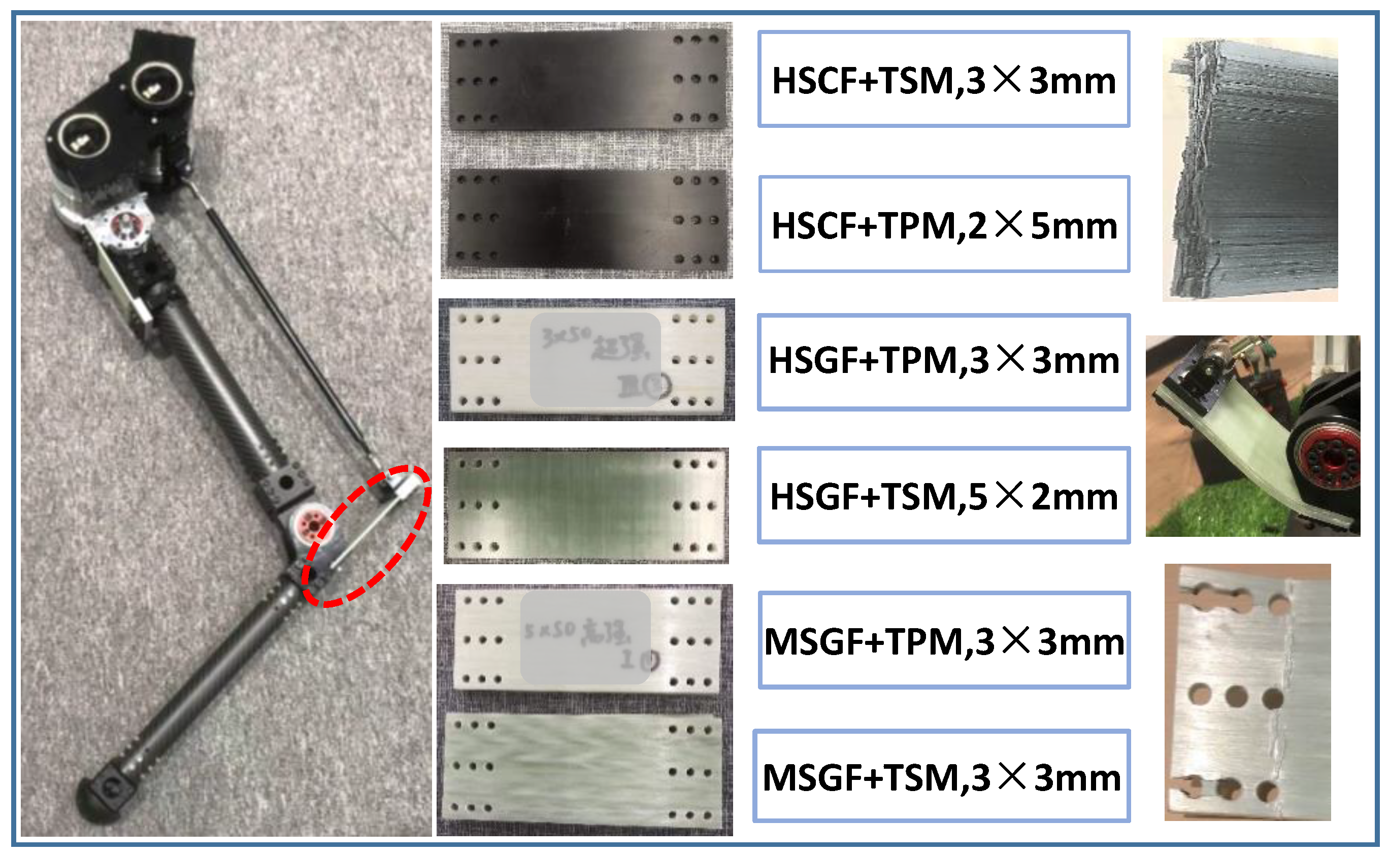
- Due to the small bending strain of carbon fiber-reinforced leaf spring, it has less ability for energy storage in this structure and is prone to brittle fracture. The material of HSCF + TPM composite has the merits of being lightweight and having good impact resistance. It may be ideal for the spring leaf of a bionic leg.
Author Contributions
Funding
Institutional Review Board Statement
Informed Consent Statement
Data Availability Statement
Acknowledgments
Conflicts of Interest
References
- Wood, B. Four legs good, two legs better. Nature 1993, 363, 587–588. [Google Scholar] [CrossRef] [PubMed]
- Zhang, G.; Ma, S.; Shen, Y. A Motion Planning Approach for Nonprehensile Manipulation and Locomotion Tasks of a Legged Robot. IEEE Trans. Robot. 2020, 36, 855–874. [Google Scholar] [CrossRef]
- He, G.; Geng, Z. Exponentially stabilizing an one-legged hopping robot with non-SLIP model in flight phase. Mechatronics 2009, 19, 364–374. [Google Scholar] [CrossRef]
- Komarsofla, A.K.; Yazdi, E.A.; Eghtesad, M. Dynamic Modeling and Control of a Novel One-Legged Hopping Robot. Robotica 2021, 39, 1692–1710. [Google Scholar] [CrossRef]
- Larin, V.B. A 3D model of one-legged hopping machine. Int. Appl. Mech. 2004, 40, 583–591. [Google Scholar] [CrossRef]
- Zhang, J.Z.; Jin, Z.L.; Zhao, Y.M. Dynamics analysis of leg mechanism of six-legged firefighting robot. J. Mech. Sci. Technol. 2018, 32, 351–361. [Google Scholar] [CrossRef]
- He, G.-P.; Tan, X.-L.; Zhang, X.-H. Modeling, motion planning, and control of one-legged hopping robot actuated by two arms. Mech. Mach. Theory 2008, 43, 33–49. [Google Scholar] [CrossRef]
- Luo, G.; Du, R.; Zhu, S. Design and Dynamic Analysis of a Compliant Leg Configuration towards the Biped Robot’s Spring-Like Walking. J. Intell. Robot. Syst. 2022, 104, 64. [Google Scholar] [CrossRef]
- Muyshondt, P.G.G.; Claes, R.; Aerts, P. Quasi-static and dynamic motions of the columellar footplate in ostrich (Struthio camelus) measured ex vivo. Hear. Res. 2018, 357, 10–24. [Google Scholar] [CrossRef] [PubMed] [Green Version]
- Schaller, N.U.; Herkner, B.; Villa, R. The intertarsal joint of the ostrich (Struthio camelus): Anatomical examination and function of passive structures in locomotion. J. Anat. 2009, 214, 830–847. [Google Scholar] [CrossRef] [PubMed]
- Smith, N.C.; Payne, R.C.; Jespers, K.J. Muscle moment arms of pelvic limb muscles of the ostrich (Struthio camelus). J. Anat. 2007, 211, 313–324. [Google Scholar] [CrossRef] [PubMed]
- Ramesh, P.; Sundaresan, S.S.; Shobana, N. Structural studies of hemoglobin from two flightless birds, ostrich and turkey: Insights into their differing oxygen-binding properties. Acta Crystallogr. D 2021, 77, 690–702. [Google Scholar] [CrossRef] [PubMed]
- Smith, N.C.; Wilson, A.M.; Jespers, K.J. Muscle architecture and functional anatomy of the pelvic limb of the ostrich (Struthio camelus). J. Anat. 2006, 209, 765–779. [Google Scholar] [CrossRef] [PubMed]
- Du, R.; Song, S.; Yuan, H. Discussion on the Stiffness of the Drive Chain in the Legs of Biped Robots. Actuators 2022, 11, 79. [Google Scholar] [CrossRef]
- Rodino, S.; Curcio, E.M.; Di Bella, A. Design, Simulation, and Preliminary Validation of a Four-Legged Robot. Machines 2020, 8, 82. [Google Scholar] [CrossRef]
- Wang, F.T.; Li, C.B.; Niu, S.H. Design and Analysis of a Spherical Robot with Rolling and Jumping Modes for Deep Space Exploration. Machines 2022, 10, 126. [Google Scholar] [CrossRef]
- Fabrègue, D.; Mouawad, B.; Hutchinson, C.R. Enhanced recovery and recrystallization of metals due to an applied current. Scr. Mater. 2014, 92, 3–6. [Google Scholar] [CrossRef]
- Pappalardo, C.M.; Guida, D. Forward and Inverse Dynamics of a Unicycle-Like Mobile Robot. Machines 2019, 7, 5. [Google Scholar] [CrossRef] [Green Version]


Publisher’s Note: MDPI stays neutral with regard to jurisdictional claims in published maps and institutional affiliations. |
© 2022 by the authors. Licensee MDPI, Basel, Switzerland. This article is an open access article distributed under the terms and conditions of the Creative Commons Attribution (CC BY) license (https://creativecommons.org/licenses/by/4.0/).
Share and Cite
Nie, D.; Du, R.; Tian, J.; Zhang, P.; Shen, F.; Gu, J.; Fu, Y. Buffering Performance Analysis of an Ostrich-like Leg Based on a Seven-Link Parallel Mechanism. Machines 2022, 10, 306. https://doi.org/10.3390/machines10050306
Nie D, Du R, Tian J, Zhang P, Shen F, Gu J, Fu Y. Buffering Performance Analysis of an Ostrich-like Leg Based on a Seven-Link Parallel Mechanism. Machines. 2022; 10(5):306. https://doi.org/10.3390/machines10050306
Chicago/Turabian StyleNie, Daming, Ruilong Du, Jiangren Tian, Pu Zhang, Fangyan Shen, Jason Gu, and Yili Fu. 2022. "Buffering Performance Analysis of an Ostrich-like Leg Based on a Seven-Link Parallel Mechanism" Machines 10, no. 5: 306. https://doi.org/10.3390/machines10050306