
A Novel Impact Feature Extraction Method Based on EMD and Sparse Decomposition for Gear Local Fault Diagnosis


Abstract
:1. Introduction
2. Theoretical Background
2.1. Empirical Mode Decomposition (EMD)
- The numbers of extreme points and zero points must be equal or at most different in one over the length of the data;
- At any data point, the average of the envelope of the local maximum and that of the local minimum must be zero.
2.2. Sparse Decomposition Based on Match Pursuit (MP)
3. The Proposed Impact Feature Extraction Method
- (1)
- The gearbox original vibration signal is collected at appropriate sampling frequency .
- (2)
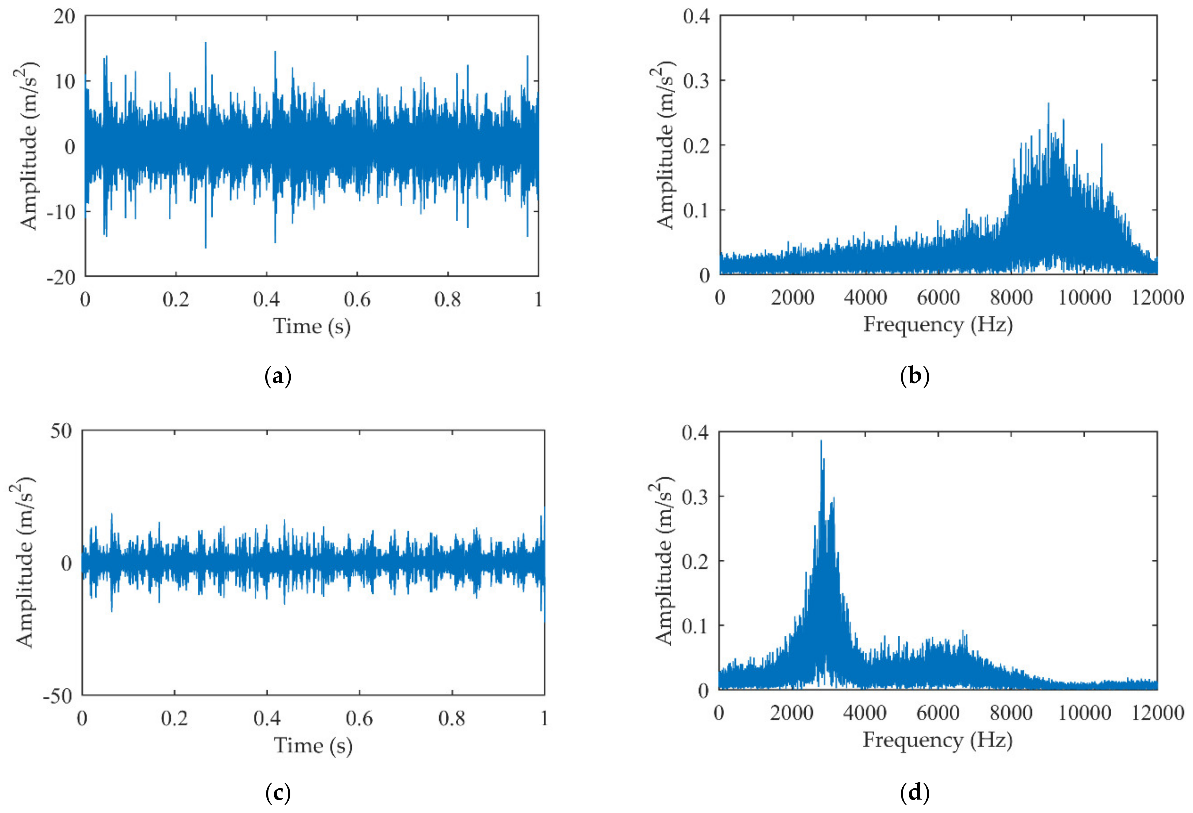
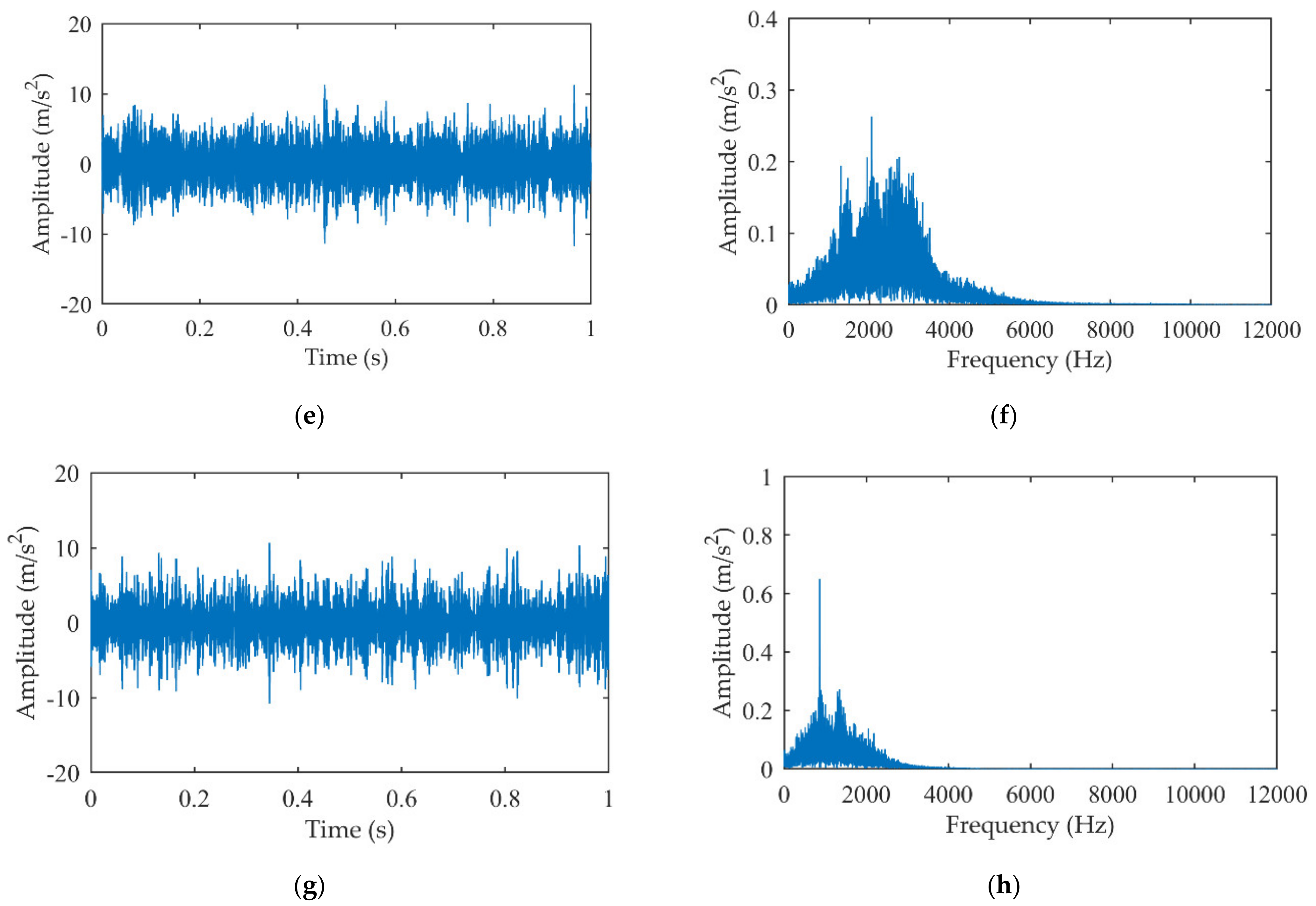
- The vibration signal is adaptively decomposed by EMD to obtain several IMFs whose frequency range changes from high to low.
- (3)
- The first few IMFs containing few gear meshing components are selected as alternatives through the amplitude spectrum. Generally, the meshing frequencies and other harmonic components remain in a lower frequency range. Therefore, those IMFs whose frequencies are above 2000 Hz are selected for further analysis.
- (4)
- The kurtosis of the alternative IMFs is calculated according to Equation (7).where is the absolute value of each point of the signal, is the average value of the signal and is the root mean square value. The kurtosis is particularly sensitive to impact signals and usually the larger it is, the more impact components the corresponding IMF includes. Therefore, the one with the highest kurtosis among the alternative IMFs is chosen as the MIMF, which has the most prominent impact characteristics and is less affected by the meshing component.
- (5)
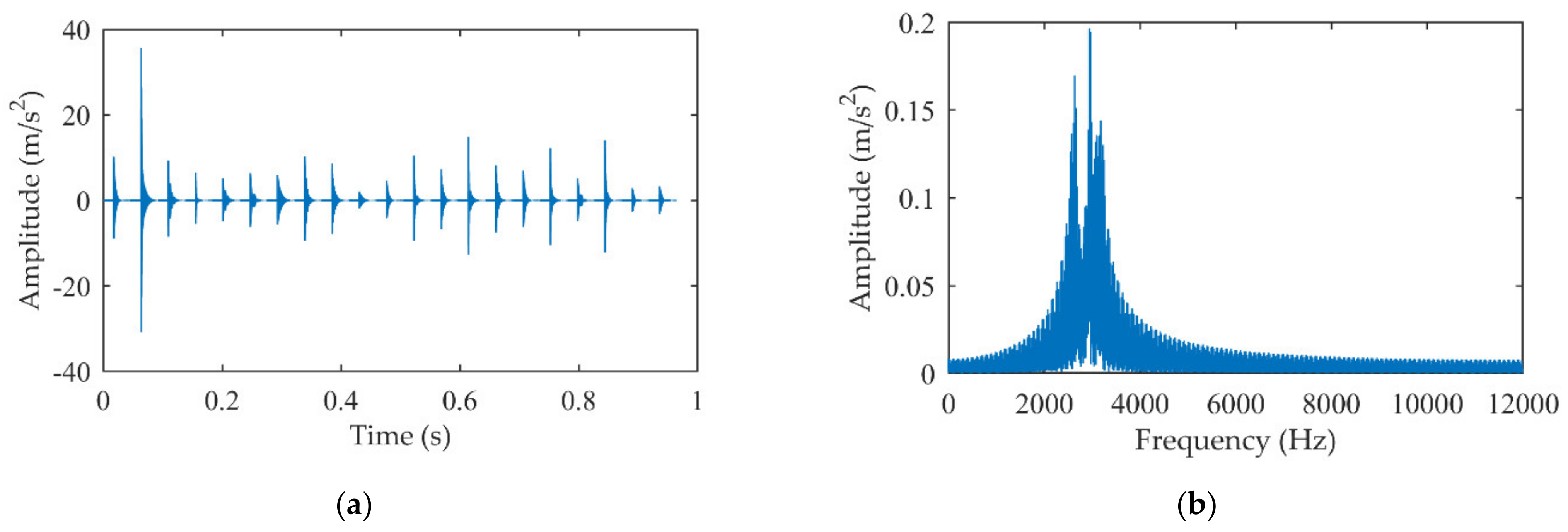
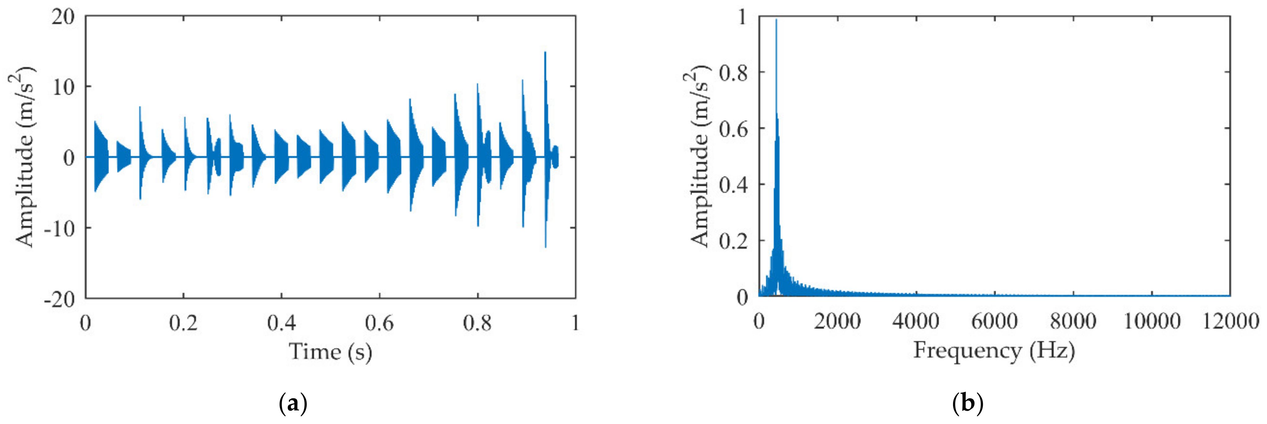
- The natural frequency and the damping ratio are identified by correlation filtering from MIMF, which are used to construct the impact dictionary .
- (6)
- To improve the operating efficiency, the original signal is divided into several segments based on the smallest fault feature period [13] and each segment signal is, respectively, reconstructed by MP. After splicing together all the reconstructed signals, the gear local fault feature signal is obtained.
4. Simulation Analysis
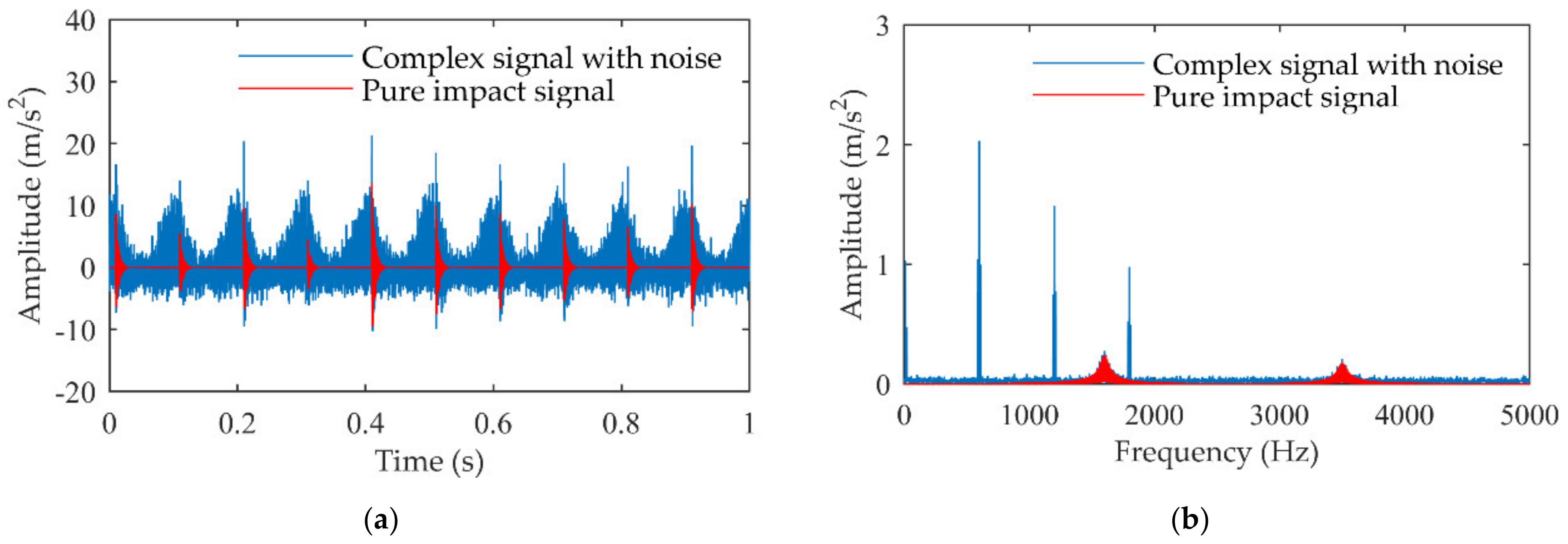
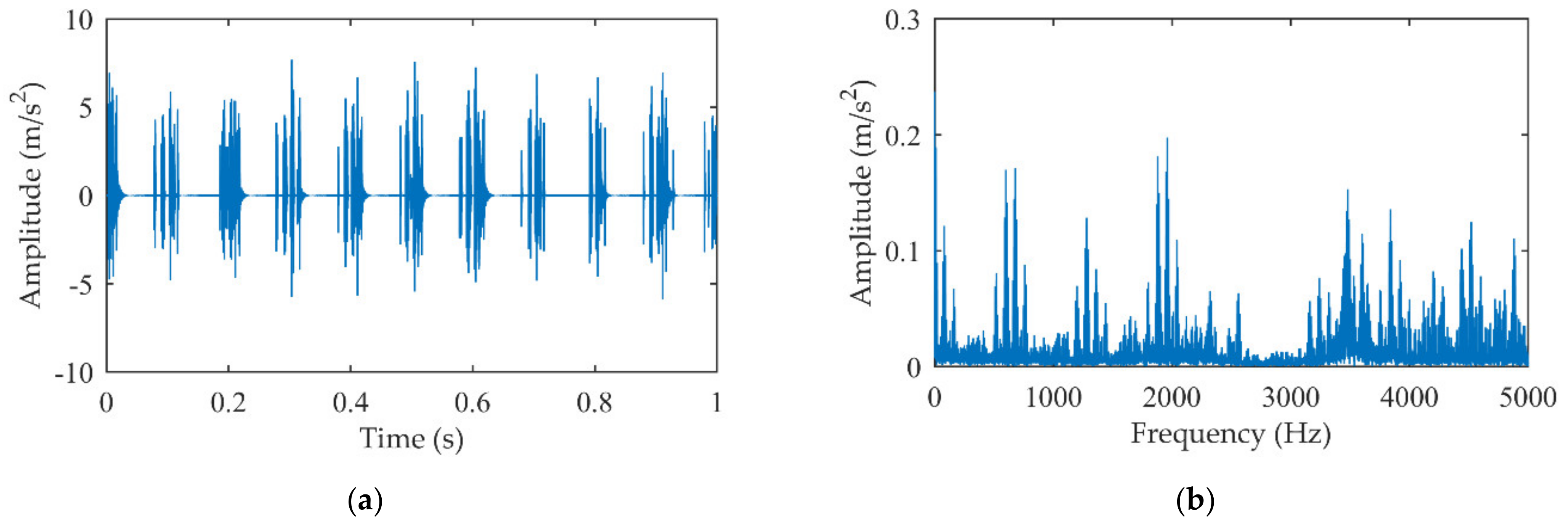
4.1. Construct Fault Simulation Signal
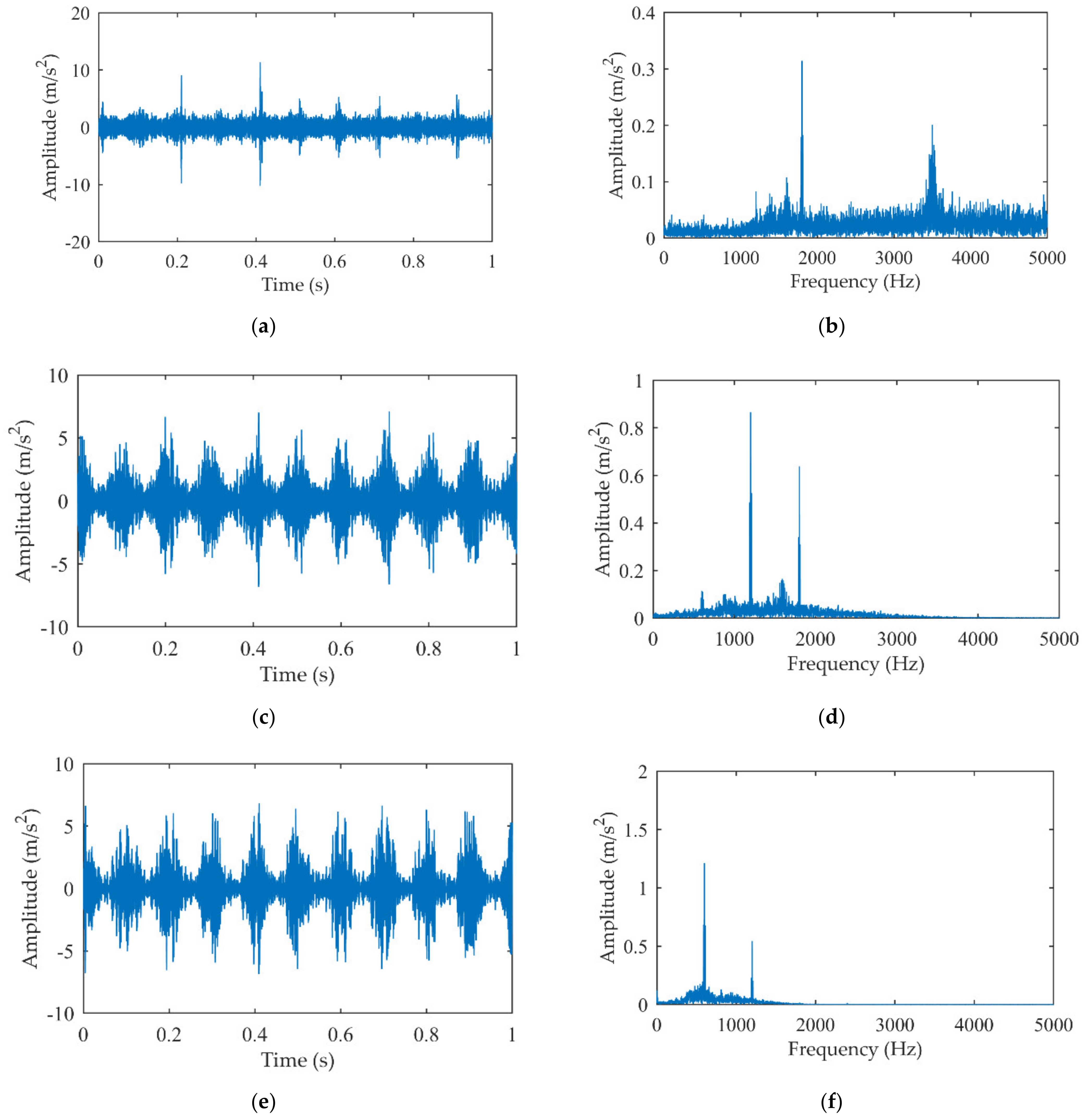
4.2. Select the Main IMF (MIMF) Based on EMD and Kurtosis
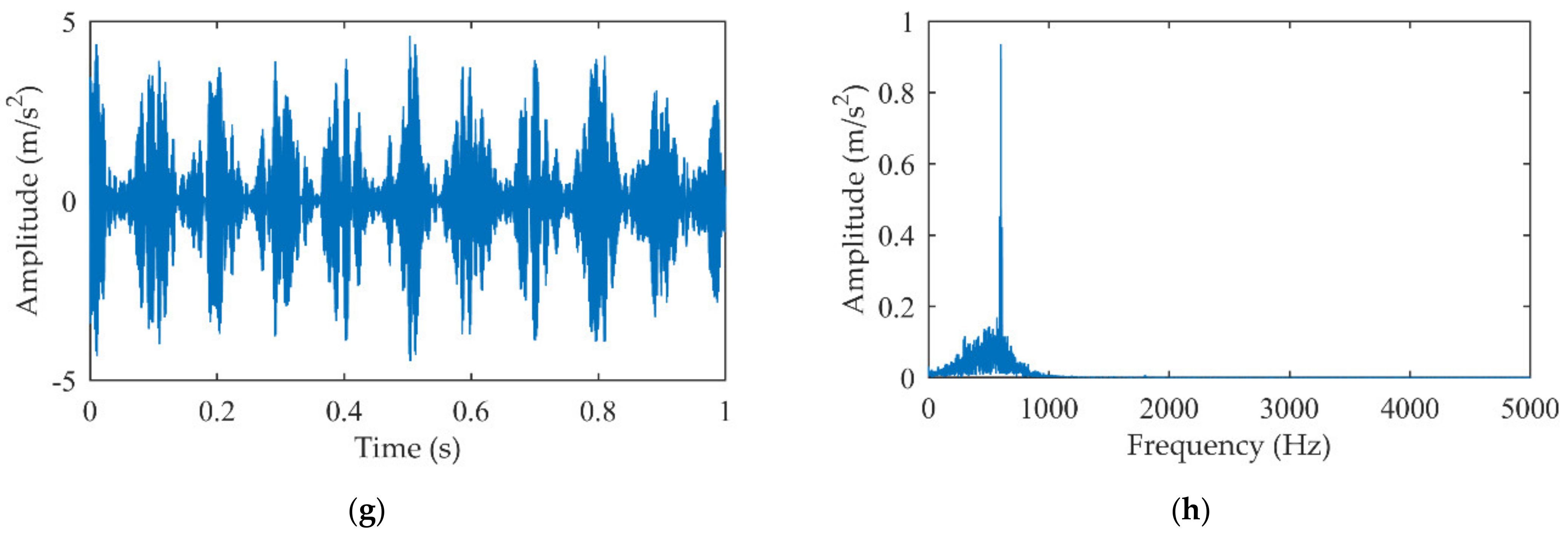
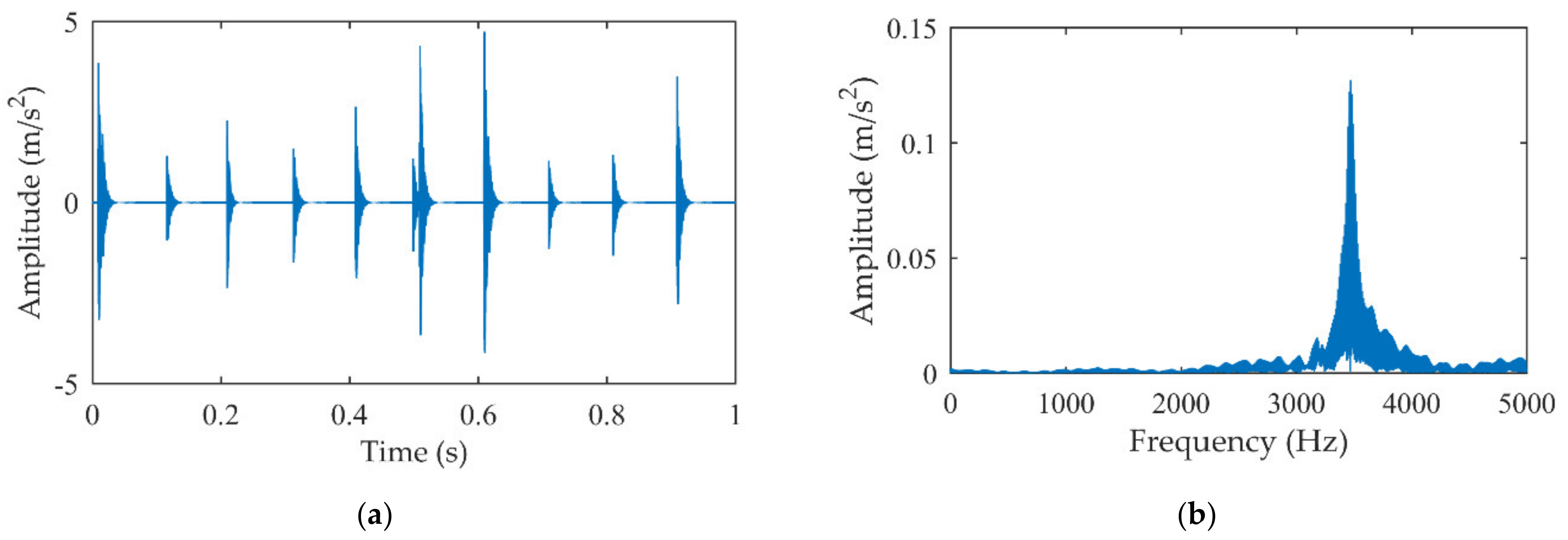
4.3. Extracting the Fault Impact Signal
4.4. Comparative Analysis
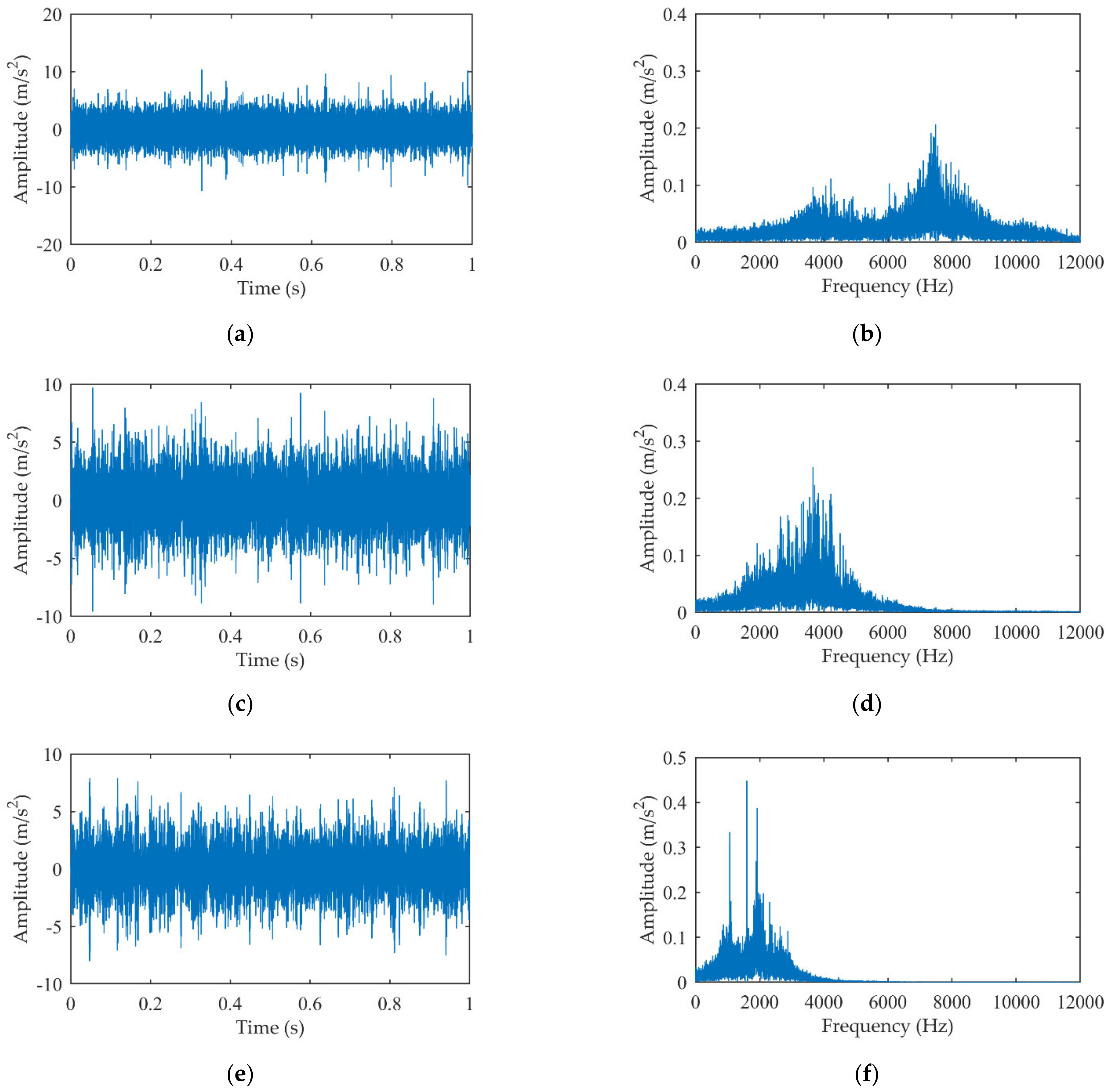
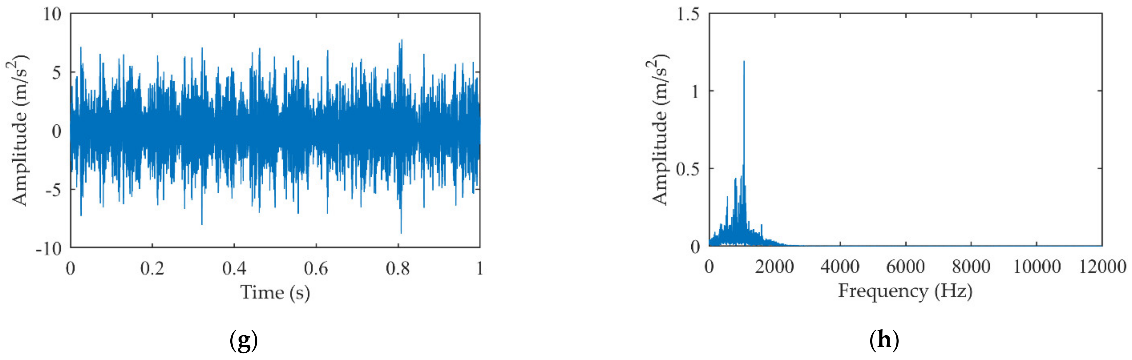
5. Experimental Analysis
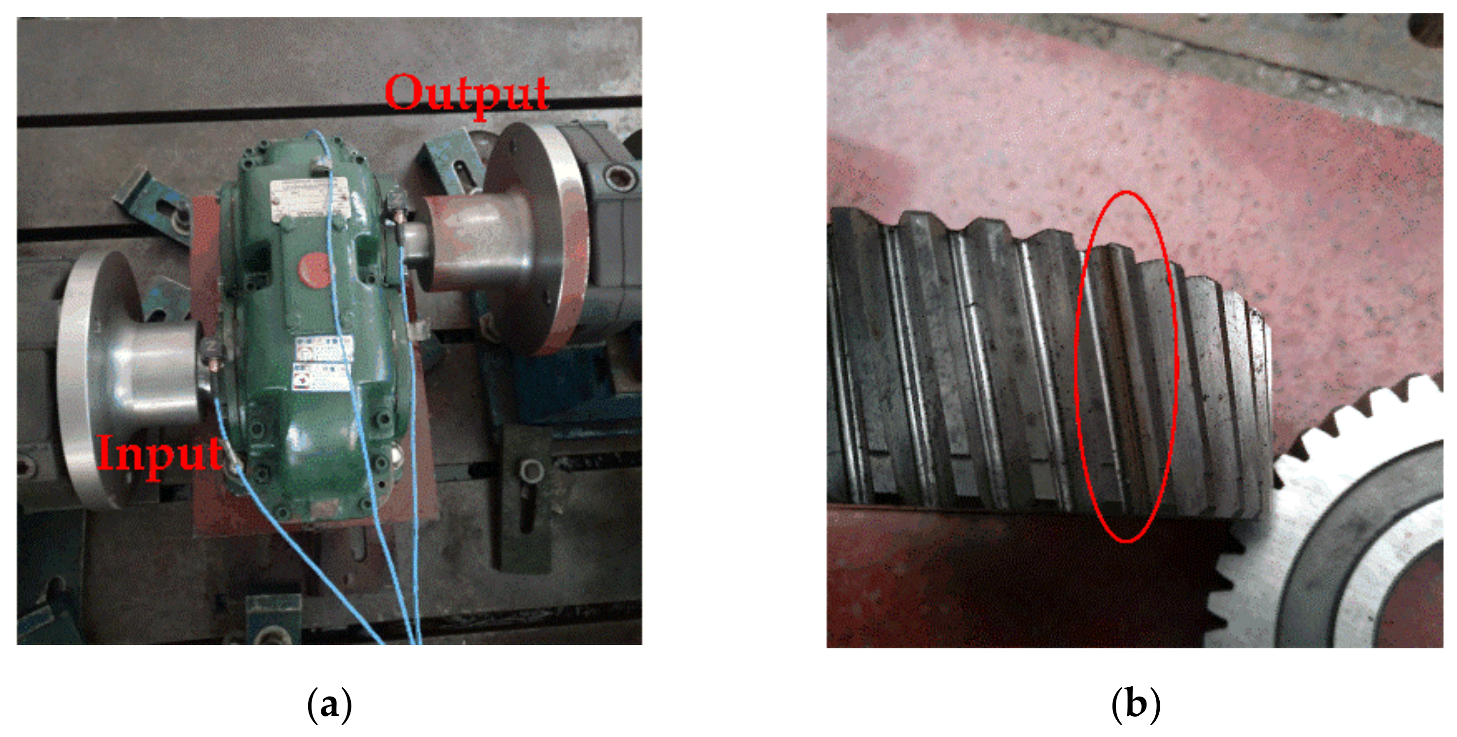
5.1. The Single-Stage Gearbox Experiment
5.2. The Five-Speed Transmission Experimental
6. Conclusions
Author Contributions
Funding
Institutional Review Board Statement
Informed Consent Statement
Data Availability Statement
Conflicts of Interest
References
- El Morsy, M.; Achtenová, G. Vehicle Gearbox Fault Diagnosis Based On Cepstrum Analysis. World Acad. Sci. Eng. Technol. Int. J. Mech. Aerosp. Ind. Mechatron. Eng. 2014, 8, 1533–1539. [Google Scholar]
- Wang, T.; Han, Q.; Chu, F.; Feng, Z. Vibration based condition monitoring and fault diagnosis of wind turbine planetary gearbox: A review. Mech. Syst. Signal Processing 2019, 126, 662–685. [Google Scholar] [CrossRef]
- Gu, H.; Liu, W.; Gao, Q.; Zhang, Y. A review on wind turbines gearbox fault diagnosis methods. J. Vibroeng. 2021, 23, 26–43. [Google Scholar]
- Jiang, F.; Ding, K.; He, G.; Sun, Y.; Wang, L. Vibration fault features of planetary gear train with cracks under time-varying flexible transfer functions. Mech. Mach. Theory 2021, 158, 104237. [Google Scholar] [CrossRef]
- Aherwar, A. An investigation on gearbox fault detection using vibration analysis techniques: A review. Aust. J. Mech. Eng. 2012, 10, 169–183. [Google Scholar] [CrossRef]
- Chen, H.; Jiang, B.; Ding, S.; Huang, B. Data-Driven Fault Diagnosis for Traction Systems in High-Speed Trains: A Survey, Challenges, and Perspect. IEEE Trans. Intell. Transp. Syst. 2020, 23, 1700–1716. [Google Scholar] [CrossRef]
- Lei, Y.; Yang, B.; Jiang, X.; Jia, F.; Li, N.; Nandi, A.K. Applications of machine learning to machine fault diagnosis: A review and roadmap. Mech. Syst. Signal Processing 2020, 138, 106587. [Google Scholar] [CrossRef]
- Yu, G. A Concentrated Time-Frequency Analysis Tool for Bearing Fault Diagnosis. IEEE Trans. Instrum. Meas. 2020, 69, 371–381. [Google Scholar] [CrossRef]
- Qin, Y.; Mao, Y.; Tang, B.; Wang, Y.; Chen, H. M-band flexible wavelet transform and its application to the fault diagnosis of planetary gear transmission systems. Mech. Syst. Signal Processing 2019, 134, 106298. [Google Scholar] [CrossRef]
- Elforjani, M.; Bechhoefer, E. Analysis of extremely modulated faulty wind turbine data using spectral kurtosis and signal intensity estimator. Renew. Energy 2018, 127, 258–268. [Google Scholar] [CrossRef]
- Cheng, J.; Yu, D.; Tang, J.; Yang, Y. Application of frequency family separation method based upon EMD and local Hilbert energy spectrum method to gear fault diagnosis. Mech. Mach. Theory 2008, 43, 712–723. [Google Scholar] [CrossRef]
- Dragomiretskiy, K.; Zosso, D. Variational mode decomposition. IEEE Trans. Signal Processing 2014, 62, 531–544. [Google Scholar] [CrossRef]
- He, G.; Ding, K.; Lin, H. Gearbox coupling modulation separation method based on match pursuit and correlation filtering. Mech. Syst. Signal Processing 2016, 66–67, 597–611. [Google Scholar] [CrossRef]
- Yang, X.; Ding, K.; He, G.; Li, Y. Double-dictionary signal decomposition method based on split augmented Lagrangian shrinkage algorithm and its application in gearbox hybrid faults diagnosis. J. Sound Vib. 2018, 432, 484–501. [Google Scholar] [CrossRef]
- Fan, W.; Cai, G.; Zhu, Z.K.; Shen, C.; Huang, W.; Shang, L. Sparse representation of transients in wavelet basis and its application in gearbox fault feature extraction. Mech. Syst. Signal Processing 2015, 56, 230–245. [Google Scholar] [CrossRef]
- Cai, G.; Selesnick, I.W.; Wang, S.; Dai, W.; Zhu, Z. Sparsity-enhanced signal decomposition via generalized minimax-concave penalty for gearbox fault diagnosis. J. Sound Vib. 2018, 432, 213–234. [Google Scholar] [CrossRef]
- Li, Y.; Ding, K.; He, G.; Jiao, X. Non-stationary vibration feature extraction method based on sparse decomposition and order tracking for gearbox fault diagnosis. Meas. J. Int. Meas. Confed. 2018, 124, 453–469. [Google Scholar] [CrossRef]
- Wang, L.; Cai, G.; Wang, J.; Jiang, X.; Zhu, Z. Dual-Enhanced Sparse Decomposition for Wind Turbine Gearbox Fault Diagnosis. IEEE Trans. Instrum. Meas. 2019, 68, 450–461. [Google Scholar] [CrossRef]
- Sun, R.B.; Yang, Z.B.; Luo, W.; Qiao, B.J.; Chen, X.F. Weighted sparse representation based on failure dynamics simulation for planetary gearbox fault diagnosis. Meas. Sci. Technol. 2019, 30, 045008. [Google Scholar] [CrossRef]
- Cai, G.; Wang, S.; Chen, X.; Ye, J.; Selesnick, I.W. Reweighted generalized minimax-concave sparse regularization and application in machinery fault diagnosis. ISA Trans. 2020, 105, 320–334. [Google Scholar] [CrossRef]
- Deng, F.; Qiang, Y.; Liu, Y.; Yang, S.; Hao, R. Adaptive parametric dictionary design of sparse representation based on fault impulse matching for rotating machinery weak fault detection. Meas. Sci. Technol. 2020, 31, 065101. [Google Scholar] [CrossRef]
- Yang, B.; Liu, R.; Chen, X. Sparse Time-Frequency Representation for Incipient Fault Diagnosis of Wind Turbine Drive Train. IEEE Trans. Instrum. Meas. 2018, 67, 2616–2627. [Google Scholar] [CrossRef]
- Huang, N.E.; Shen, Z.; Long, S.R.; Wu, M.C.; Snin, H.H.; Zheng, Q.; Yen, N.C.; Tung, C.C.; Liu, H.H. The empirical mode decomposition and the Hubert spectrum for nonlinear and non-stationary time series analysis. Proc. R. Soc. Lond. Ser. A Math. Phys. Eng. Sci. 1998, 454, 903–995. [Google Scholar] [CrossRef]
- Lei, Y.; Lin, J.; He, Z.; Zuo, M.J. A review on empirical mode decomposition in fault diagnosis of rotating machinery. Mech. Syst. Signal Processing 2013, 35, 108–126. [Google Scholar] [CrossRef]
- Xia, S.; Zhang, J.; Ye, S.; Xu, B.; Xiang, J.; Tang, H. A mechanical fault detection strategy based on the doubly iterative empirical mode decomposition. Appl. Acoust. 2019, 155, 346–357. [Google Scholar] [CrossRef]
- Wang, J.; Du, G.; Zhu, Z.; Shen, C.; He, Q. Fault diagnosis of rotating machines based on the EMD manifold. Mech. Syst. Signal Processing 2020, 135, 106443. [Google Scholar] [CrossRef]
- Han, D.; Zhao, N.; Shi, P. Gear fault feature extraction and diagnosis method under different load excitation based on EMD, PSO-SVM and fractal box dimension. J. Mech. Sci. Technol. 2019, 33, 487–494. [Google Scholar] [CrossRef]
- Du, W.T.; Zeng, Q.; Shao, Y.M.; Wang, L.M.; Ding, X.X. Multi-scale demodulation for fault diagnosis based on a weighted-EMD de-noising technique and time–frequency envelope analysis. Appl. Sci. 2020, 10, 7796. [Google Scholar] [CrossRef]
- Akram, M.; Khushnood, S.; Tariq, S.; Ali, H.; Nizam, L. Vibration Based Gear Fault Diagnosis under Empirical Mode Decomposition and Power Spectrum Density Analysis. Adv. Sci. Technol. Res. J. 2019, 13, 192–200. [Google Scholar] [CrossRef]
- Inturi, V.; Pratyush, A.S.; Sabareesh, G.R. Detection of Local Gear Tooth Defects on a Multistage Gearbox Operating Under Fluctuating Speeds Using DWT and EMD Analysis. Arab. J. Sci. Eng. 2021, 46, 11999–12008. [Google Scholar] [CrossRef]
- Li, C.; Yu, G.; Fu, B.; Hu, H.; Zhu, X.; Zhu, Q. Fault separation and detection for compound bearing-gear fault condition based on decomposition of marginal hilbert spectrum. IEEE Access 2019, 7, 110518–110530. [Google Scholar] [CrossRef]
- Mallat, S.G.; Zhang, Z. Matching Pursuits With Time-Frequency Dictionaries. IEEE Trans. Signal Processing 1993, 41, 3397–3415. [Google Scholar] [CrossRef] [Green Version]


| Intrinsic Mode Function (IMF) | Kurtosis |
|---|---|
| IMF1 | 5.258 |
| IMF2 | 4.373 |
| IMF3 | 4.591 |
| IMF4 | 3.890 |
| CC | RMSE | RRMSE | |
|---|---|---|---|
| The proposed method | 0.4121 | 0.6983 | 0.0735 |
| The traditional sparse decomposition | 0.2241 | 1.0408 | 0.1177 |
| The EMD + MP | 0.3981 | 0.7091 | 0.0822 |
| Intrinsic Mode Function (IMF) | Kurtosis |
|---|---|
| IMF1 | 2.606 |
| IMF2 | 3.148 |
| IMF3 | 3.124 |
| IMF4 | 3.106 |
| Parameter | The Constantly Meshed Gear Pair | The Fifth Gear Pair | ||
|---|---|---|---|---|
| - | Drive wheel | Driven wheel | Drive wheel | Driven wheel |
| Gear number | 26 | 38 | 42 | 22 |
| Rotational frequency (Hz) | 16.67 | 11.40 | 11.40 | 21.77 |
| Mesh frequency (Hz) | 433.33 | 478.94 | ||
| Intrinsic Mode Function (IMF) | Kurtosis |
|---|---|
| IMF1 | 2.728 |
| IMF2 | 5.477 |
| IMF3 | 2.988 |
| IMF4 | 3.442 |
Publisher’s Note: MDPI stays neutral with regard to jurisdictional claims in published maps and institutional affiliations. |
© 2022 by the authors. Licensee MDPI, Basel, Switzerland. This article is an open access article distributed under the terms and conditions of the Creative Commons Attribution (CC BY) license (https://creativecommons.org/licenses/by/4.0/).
Share and Cite
Liu, Z.; Ding, K.; Lin, H.; He, G.; Du, C.; Chen, Z. A Novel Impact Feature Extraction Method Based on EMD and Sparse Decomposition for Gear Local Fault Diagnosis. Machines 2022, 10, 242. https://doi.org/10.3390/machines10040242
Liu Z, Ding K, Lin H, He G, Du C, Chen Z. A Novel Impact Feature Extraction Method Based on EMD and Sparse Decomposition for Gear Local Fault Diagnosis. Machines. 2022; 10(4):242. https://doi.org/10.3390/machines10040242
Chicago/Turabian StyleLiu, Zhongze, Kang Ding, Huibin Lin, Guolin He, Canyi Du, and Zhuyun Chen. 2022. "A Novel Impact Feature Extraction Method Based on EMD and Sparse Decomposition for Gear Local Fault Diagnosis" Machines 10, no. 4: 242. https://doi.org/10.3390/machines10040242