
A Comprehensive Survey on Fault Tolerance in Multiphase AC Drives, Part 1: General Overview Considering Multiple Fault Types

 ,
,  ,
,  ,
,  and
and 
Abstract
:1. Introduction

| References | Control Unit | Current Sensor | Dc Capacitor | Dc Volt. Sensor | Dc Volt. Excess | Dc Volt. Shortage | High-res. Connects. | Machine Cooling | Magnet Demag. | Mechanical | Resolver/Encoder | Stator SC | Supply OC/SC | Switch SC | Switch/Phase OC |
|---|---|---|---|---|---|---|---|---|---|---|---|---|---|---|---|
| [56] | DT | - | - | - | - | - | - | - | - | - | - | - | - | - | - |
| [57] | - | D | - | - | - | - | - | - | - | - | - | - | - | - | D |
| [58] | - | DT | - | DT | - | - | - | - | - | - | DT | - | - | - | DT |
| [59] | - | - | - | - | - | - | D | - | - | - | - | - | - | - | - |
| [60] | - | - | - | - | - | - | D | D | - | - | - | - | - | - | - |
| [61] | - | - | - | - | - | - | D | - | - | - | - | D | - | - | - |
| [62] | - | - | - | - | - | - | D | - | - | D | - | - | - | - | D |
| [63,64] | - | - | - | - | - | - | D | - | - | - | - | - | - | - | D |
| [65,66,67] | - | - | - | - | - | - | DT | - | - | - | - | - | - | - | - |
| [68] | - | - | - | - | - | - | DT | - | DT | - | - | - | - | - | - |
| [69] | - | - | - | - | - | - | DT | - | - | - | - | - | - | - | DT |
| [70,71,72,73] | - | - | - | - | - | - | - | D | - | - | - | - | - | - | - |
| [74,75,76,77,78] | - | - | - | - | - | - | - | - | DT | - | - | - | - | - | - |
| [79,80,81,82,83,84,85] | - | - | - | - | - | - | - | - | - | D | - | - | - | - | - |
| [86,87] | - | - | - | - | - | - | - | - | - | - | DT | - | - | - | - |
| [88,89,90,91,92] | - | - | - | - | - | - | - | - | - | - | - | D | - | - | - |
| [93,94,95,96,97,98] | - | - | - | - | - | - | - | - | - | - | - | DT | - | - | - |
| [99] | - | - | - | - | - | - | - | - | - | - | - | DT | - | DT | - |
| [100] | - | - | - | - | - | - | - | - | - | - | - | DT | - | - | DT |
| [101] | - | - | - | - | - | - | - | - | - | - | - | DT | - | - | T |
| [102] | - | - | - | - | - | - | - | - | - | - | - | - | - | D | DT |
| [103] | - | - | - | - | - | - | - | - | - | - | - | - | - | DT | DT |
| [14,104,105,106,107,108,109,110,111,112,113,114,115] | - | - | - | - | - | - | - | - | - | - | - | - | - | - | D |
| [116,117,118,119,120,121,122,123,124,125,126] | - | - | - | - | - | - | - | - | - | - | - | - | - | - | DT |
| [127] | - | - | - | - | - | - | - | - | - | - | T | - | - | - | DT |
| [128] | - | - | - | - | - | - | - | - | - | - | - | T | - | - | DT |
| [129] | - | - | T | - | - | T | - | - | T | - | - | T | - | - | - |
| [130] | - | - | T | - | - | - | - | - | - | - | T | T | - | T | T |
| [27] | - | - | T | - | - | - | - | - | - | - | - | T | - | T | T |
| [131] | - | - | - | - | T | - | - | - | - | - | - | - | - | - | - |
| [132] | - | - | - | - | T | - | - | - | - | - | - | - | - | - | T |
| [7,8,9,133,134,135,136,137,138,139,140,141,142,143,144,145,146,147,148,149,150,151,152,153,154,155,156,157,158,159,160] | - | - | - | - | - | T | - | - | - | - | - | - | - | - | - |
| [161] | - | - | - | - | - | T | - | - | - | - | T | - | - | - | T |
| [162,163,164,165,166,167] | - | - | - | - | - | T | - | - | - | - | - | T | - | - | T |
| [168] | - | - | - | - | - | T | - | - | - | - | - | - | - | T | - |
| [169,170,171,172,173,174] | - | - | - | - | - | T | - | - | - | - | - | - | - | - | T |
| [175] | - | - | - | - | - | - | T | - | - | - | - | - | - | - | - |
| [176,177] | - | - | - | - | - | - | - | - | T | - | - | T | - | - | - |
| [178] | - | - | - | - | - | - | - | - | T | - | - | T | - | - | T |
| [179,180] | - | - | - | - | - | - | - | - | - | T | - | - | - | - | - |
| [181,182,183,184,185,186,187,188,189,190,191,192,193,194,195,196,197,198,199,200,201,202,203,204,205,206,207,208] | - | - | - | - | - | - | - | - | - | - | T | - | - | - | - |
| [209] | - | - | - | - | - | - | - | - | - | - | T | T | - | - | - |
| [210,211,212] | - | - | - | - | - | - | - | - | - | - | T | T | - | - | T |
| [213,214,215,216,217,218,219] | - | - | - | - | - | - | - | - | - | - | T | - | - | - | T |
| [220,221,222,223,224,225,226,227,228,229,230,231,232,233,234,235,236,237,238] | - | - | - | - | - | - | - | - | - | - | - | T | - | - | - |
| [239] | - | - | - | - | - | - | - | - | - | - | - | T | T | T | T |
| [240,241,242,243] | - | - | - | - | - | - | - | - | - | - | - | T | - | T | - |
| [244,245,246,247] | - | - | - | - | - | - | - | - | - | - | - | T | - | T | T |
| [28,248,249,250,251,252,253,254,255,256,257,258,259,260,261,262,263,264,265,266,267,268,269,270,271,272] | - | - | - | - | - | - | - | - | - | - | - | T | - | - | T |
| [273] | - | - | - | - | - | - | - | - | - | - | - | - | - | T | - |
| [13,274,275,276,277] | - | - | - | - | - | - | - | - | - | - | - | - | - | T | T |
| [15,22,278,279,280,281,282,283,284,285,286,287,288,289,290,291,292,293,294,295,296,297,298,299,300,301,302,303,304,305,306,307,308,309,310,311,312,313,314,315,316,317,318,319,320,321,322,323,324,325,326,327,328,329,330,331,332,333,334,335,336,337,338,339,340,341,342,343,344,345,346,347,348,349,350,351,352,353,354,355,356,357,358,359,360,361,362,363,364,365,366,367,368,369,370,371,372,373,374,375,376,377,378,379,380,381,382,383,384,385,386,387,388,389,390,391,392,393,394,395,396,397,398,399,400,401,402,403,404,405,406,407,408,409,410,411,412,413,414,415,416,417,418,419,420,421,422,423,424,425,426,427,428,429,430,431,432,433,434,435,436,437,438,439,440,441,442,443,444,445,446,447,448,449,450,451] | - | - | - | - | - | - | - | - | - | - | - | - | - | - | T |
| Section | Section 12.5 | Section 12.4 | Section 12.1 | Section 12.3 | Section 9 | Section 8 | Section 4 | Section 10 | Section 11 | Section 12.6 | Section 7 | Section 5 | Section 12.2 | Section 6 | Part 2 |
| Application | References |
|---|---|
| Aerospace | [13,14,25,26,52,53,93,98,99,100,101,130,161,167,211,212,226,227,228,229,230,231,236,237,238,240,244,246,260,265,266,267,270,272,288,303,304,305,306,307,330,391,452] |
| Automotive vehicles | [3,16,22,27,28,48,56,91,92,94,117,119,178,181,182,209,217,219,220,221,243,248,249,250,264,282,358,361,363,364,365,366,367,368,386,453] |
| Elevator | [439] |
| Marine energy | [57,291,295,371] |
| Metal industry | [269,345] |
| Ships | [203,271,332,333,417,420,440,454] |
| Wind energy | [24,54,123,287,336,340,354,409,455] |
| Main Topic | References |
|---|---|
| General | [1,2,29,30,31,32,33] |
| Control and PWM | [4,34,35,36,37,38,39,40,41,42,43,44,45] |
| Converter topologies | [4,43,46,52] |
| Fault tolerance | [24,45,47] |
| Machine design | [34,55] |
| Transportation | [3,16,36,48,49,50,51,52,53] |
| Wind energy | [24,54] |
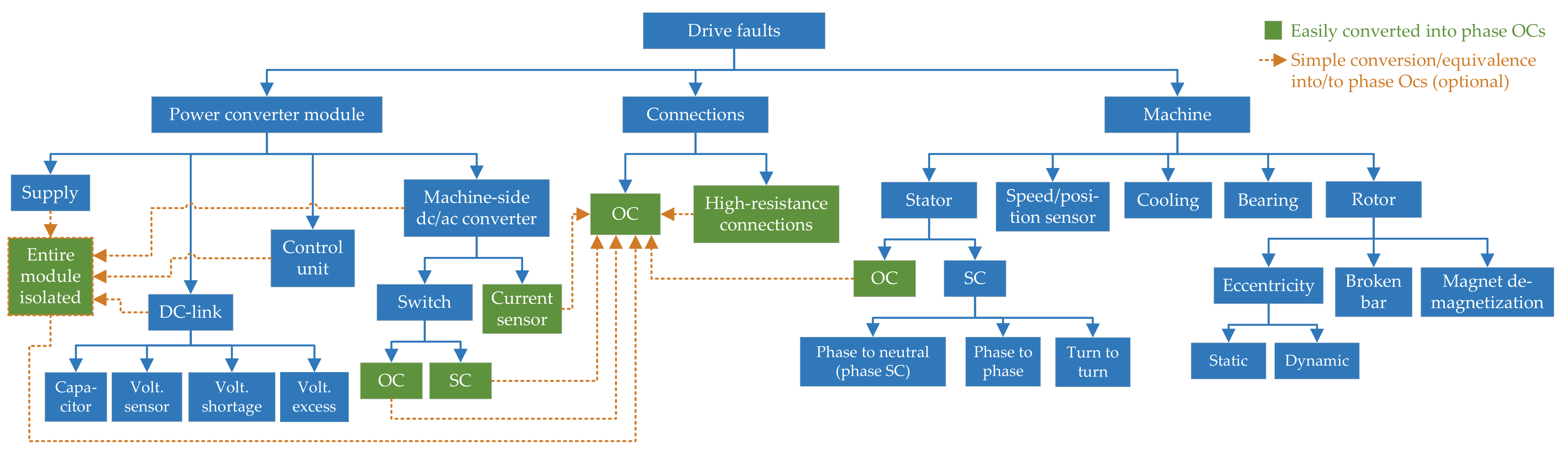
2. Main Fault Types and Literature Classification according to Studied Topics

3. Types of Multiphase Drives and Vector Space Decomposition (VSD)
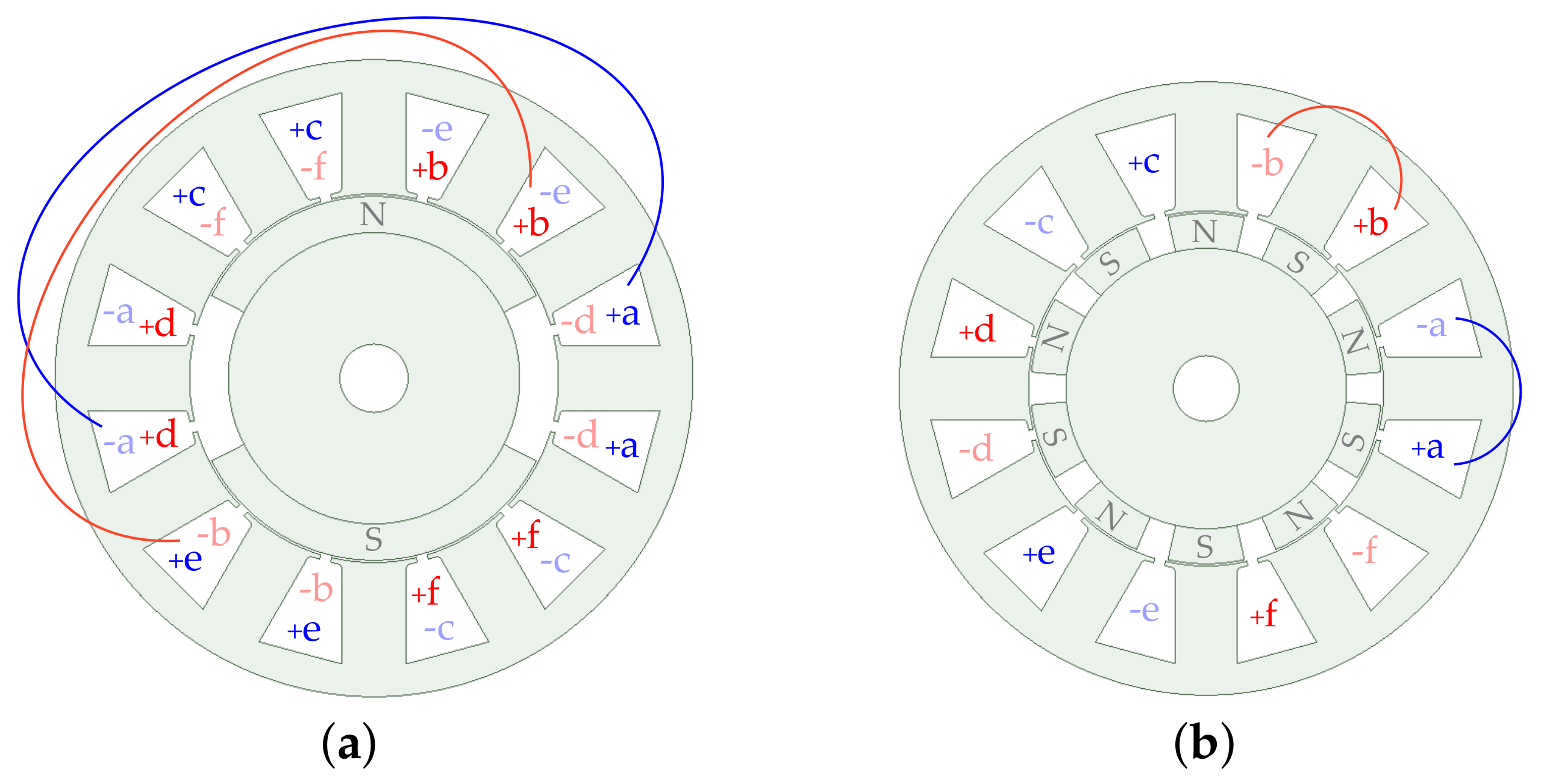
3.1. Types of Multiphase Machines and Stator Phase Configurations
3.1.1. Stator Phase Splitting
- If “no phase splitting” is applied, there is electrical connection between all phases (e.g., one star with one neutral point), and the stator can be considered a single n-phase winding;
- With “single-phase splitting”, there is no connection between any stator phases (e.g., open-end winding topologies), and the stator can be seen as n single-phase windings;
- With “l-phase splitting”, a stator winding of composite phase number n is composed of sets of l phases (), electrically isolated from each other. For example, stars with separate neutral points. It is common to select , given the widely spread knowledge and technology for three-phase systems [24,131,132,305,353]. Nevertheless, e.g., is sometimes chosen [303,405,421,431,432,469].
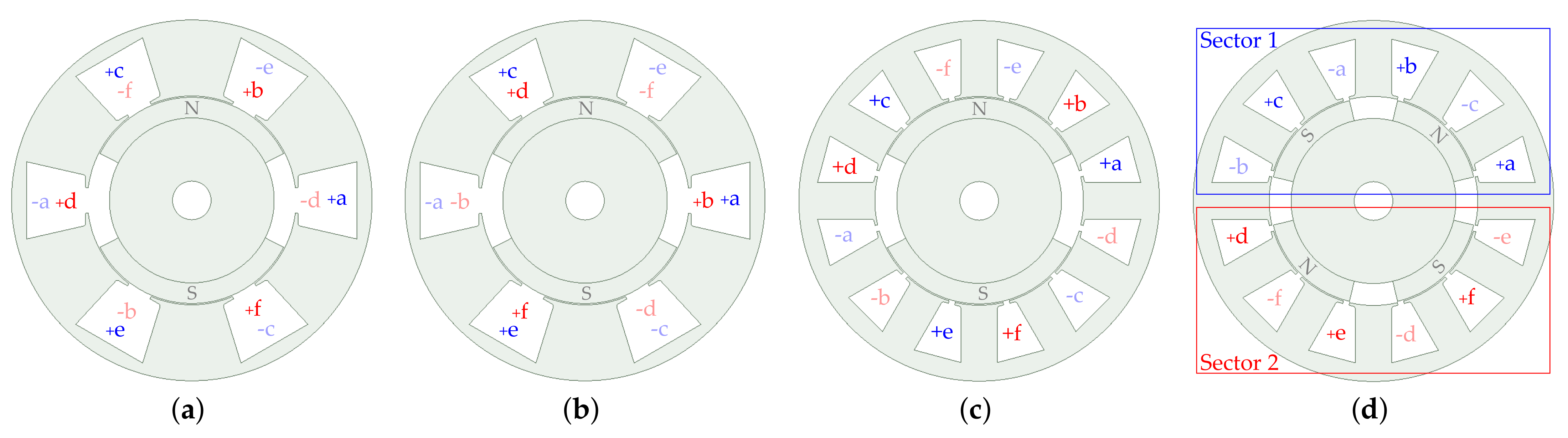
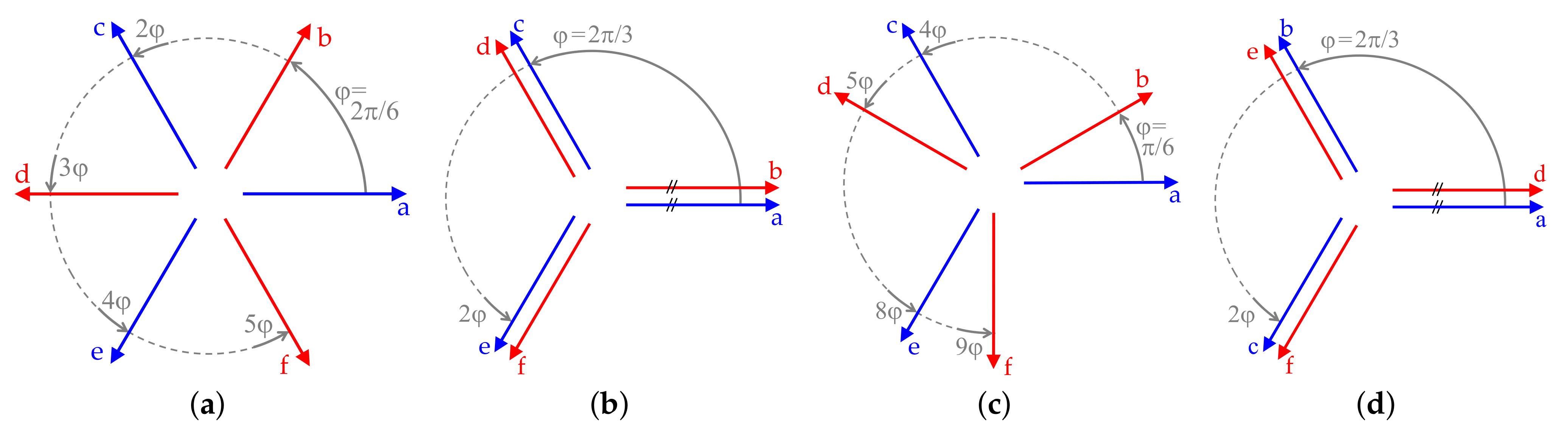
3.1.2. Stator Winding Spatial Arrangements (WSAs)


3.1.2.1. Symmetrical WSA
3.1.2.2. No-Phase-Shift WSA
3.1.2.3. Asymmetrical WSA
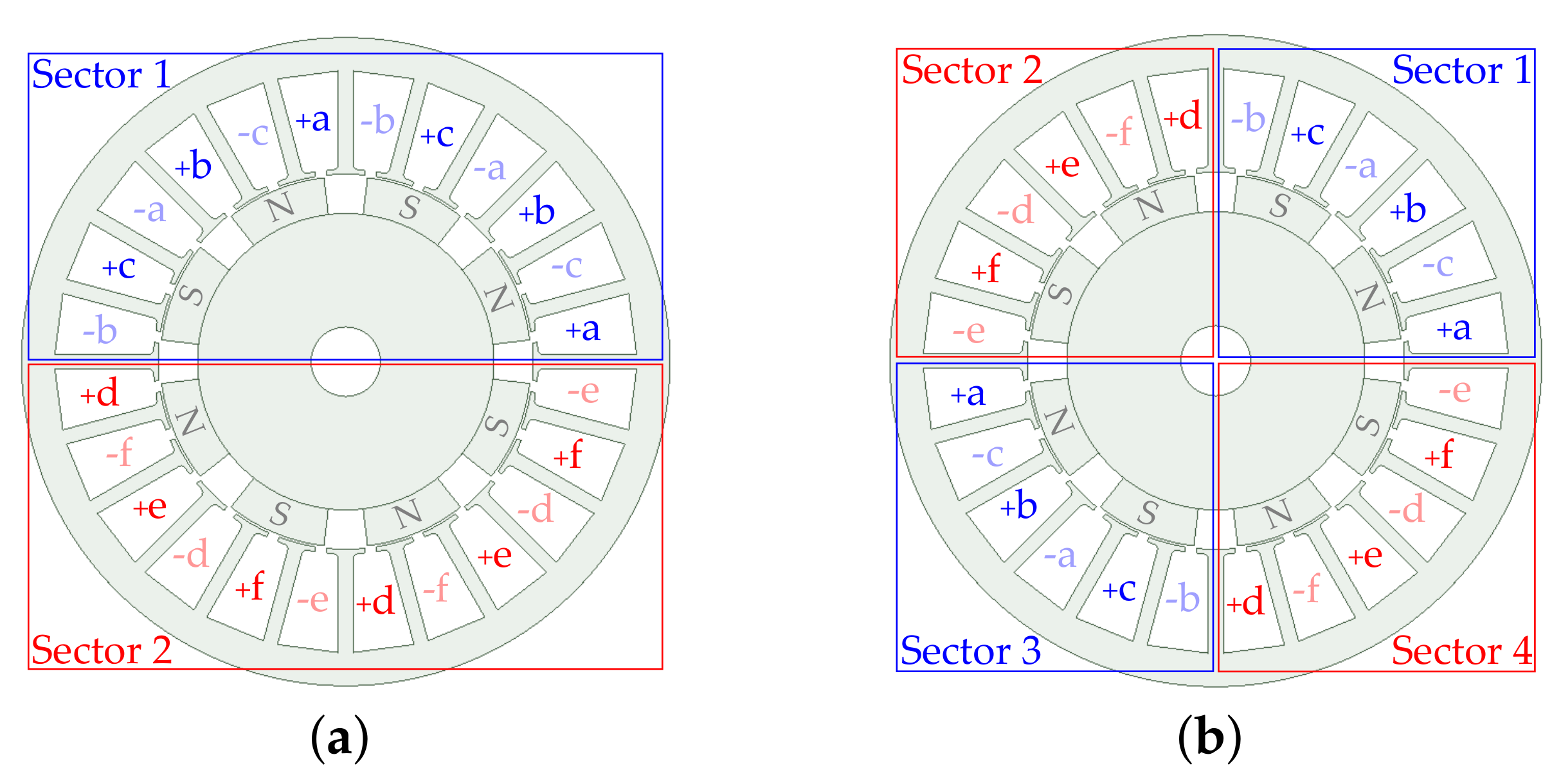
3.1.2.4. Multisector WSA

3.1.2.5. Overlapping and Non-Overlapping Windings


3.1.3. Stator Phase Connections

3.1.4. Literature Classification according to Machine Type and Stator Configuration
| n | WSA | FSCW | Splitting | Rotor | References | |
|---|---|---|---|---|---|---|
| 4 | Sym. | No | No | 0 | IM | [310] |
| 4 | Sym. | Yes | 1-ph. | − | PMSM | [163,165,228,239,266] |
| 4 | Sym. | Yes | No | 0 | PMSM | [232] |
| 5 | Sym. | No | 1-ph. | − | IM | [193,194,362,406,451] |
| 5 | Sym. | No | 1-ph. | − | PMSM | [273,403] |
| 5 | Sym. | No | No | 0 | IM | [9,41,69,114,115,116,138,142,150,151,152,153,189,190,202,218,253,310,317,318,319,320,321,322,323,324,325,326,327,328,329,410,411,427,428,429] |
| 5 | Sym. | No | No | 0 | PMaSynRM | [84,104,309,404,483] |
| 5 | Sym. | No | No | 0 | WFSM | [416] |
| 5 | Sym. | No | No | 1 | IM | [410,411,412,428] |
| 5 | Sym. | No | No | 1 | WFSM | [416] |
| 5 | Sym. | No | No | − | PMaSynRM | [423] |
| 5 | Sym. | No | No | 0 | PMSM | [8,68,76,77,78,86,105,106,136,141,200,201,208,216,217,249,250,251,252,333,383,384,385,386,387,388,389,390,391,392,393,394,395,396,400,402,414,440,448] |
| 5 | Sym. | No | No | 1 | PMSM | [141,389,390] |
| 5 | Sym. | No | No | 2 | PMSM | [141,390] |
| 5 | Sym. | Yes | 1-ph. | − | PMSM | [89,90,91,95,127,130,133,162,163,164,187,226,227,233,234,241,248,263,264,267,268,304,363,365,444,445] |
| 5 | Sym. | Yes | 1-ph. | − | Hybrid excit. | [94] |
| 5 | Sym. | Yes | No | 0 | PMSM | [59,92,102,111,117,118,119,166,219,232,254,255,256,257,262,357,358,359,360,361,366,367,379,380,381,397,398,446,447] |
| 5 | Sym. | Yes | − | − | PMSM | [209,297,442] |
| 5 | Sym. | − | No | 0 | PMSM | [57,107,108,110,175,181,186,369,370,371] |
| 5 | Sym. | − | No | 0 | RL load | [149,155,159] |
| 5 | Sym. | − | No | 0 | − | [148] |
| 5 | Sym. | − | − | − | PMSM | [182,291,295] |
| 6 | Asym. | No | 1-ph. | − | IM | [415] |
| 6 | Asym. | No | 3-ph. | 0 | IM | [80,81,82,83,112,113,126,131,132,143,144,145,146,156,157,158,161,173,202,203,204,205,206,207,261,310,311,312,334,335,336,337,338,339,340,341,342,343,433,434,435,436] |
| 6 | Asym. | No | 3-ph. | 0 | PMSM | [28,58,63,64,65,70,71,72,73,74,75,87,88,103,109,134,135,137,154,170,171,176,177,179,276,277,278,279,280,281,282,283,284,285,286,287,288] |
| 6 | Asym. | No | 3-ph. | 0 | SynRM | [247] |
| 6 | Asym. | No | 3-ph. | 0 | WFSM | [15,417,454] |
| 6 | Asym. | No | No | 0 | IM | [144,213,214,310,311,312,334,341,342,343,382,433,434,435,437,438] |
| 6 | Asym. | No | No | 0 | PMSM | [137,170,171,313,314,315,356] |
| 6 | Asym. | No | No | Other | PMSM | [372] |
| 6 | Asym. | No | Other | Other | IM | [413] |
| 6 | Asym. | No | − | − | PMSM | [368] |
| 6 | Asym. | Yes | 1-ph. | − | PMSM | [220] |
| 6 | Asym. | Yes | 3-ph. | 0 | PMSM | [215,258,259,419] |
| 6 | Asym. | Yes | No | 0 | PMSM | [351] |
| 6 | Asym. | − | 3-ph. | 0 | PMSM | [121,122,125,139,191,192,299,300] |
| 6 | Asym. | − | No | 0 | PMSM | [347,348,349] |
| 6 | Multisec. | No | 3-ph. | 0 | IM | [261,418,436] |
| 6 | Multisec. | No | 3-ph. | 0 | PMSM | [179,230,305] |
| 6 | Multisec. | No | 3-ph. | 0 | SynRM | [247,450] |
| 6 | Multisec. | No | − | − | PMSM | [425] |
| 6 | Multisec. | Yes | 3-ph. | 0 | PMSM | [56,215,246,258,259,346] |
| 6 | Multisec. | Yes | No | 0 | PMSM | [346] |
| 6 | No-ph. | No | 3-ph. | 0 | IM | [312,424] |
| 6 | No-ph. | No | 3-ph. | 0 | PMSM | [169,316] |
| 6 | No-ph. | No | No | 0 | IM | [312] |
| 6 | No-ph. | − | No | 0 | PMSM | [302] |
| 6 | Sym. | No | 1-ph. | − | IM | [271] |
| 6 | Sym. | No | 3-ph. | 0 | IM | [62,79,82,202,312,344,377,407,408] |
| 6 | Sym. | No | 3-ph. | 0 | SynRM | [308] |
| 6 | Sym. | No | 3-ph. | 2 | IM | [344,408] |
| 6 | Sym. | No | No | 0 | IM | [120,123,172,261,275,292,312,344,377,436] |
| 6 | Sym. | No | No | 0 | PMSM | [331] |
| 6 | Sym. | No | No | 0 | SynRM | [308] |
| 6 | Sym. | No | No | 1 | IM | [344,408] |
| 6 | Sym. | No | Other | Other | PMSM | [13,14,345] |
| 6 | Sym. | No | − | 0 | IM | [293,294] |
| 6 | Sym. | No | − | − | PMSM | [297] |
| 6 | Sym. | Yes | 1-ph. | − | PMSM | [93,96,99,128,163,210,211,212,223,240,265] |
| 6 | Sym. | Yes | 3-ph. | 0 | PMSM | [100,101,215,222,229,230,258,259,260,265,419] |
| 6 | Sym. | Yes | No | 0 | PMSM | [101,232,330] |
| 6 | Sym. | Yes | − | − | Hybrid excit. | [178] |
| 6 | Sym. | Yes | − | − | PMSM | [221,225,231,441] |
| 6 | Sym. | − | 1-ph. | − | PMSM | [13] |
| n | WSA | FSCW | Splitting | Rotor | References | |
|---|---|---|---|---|---|---|
| 7 | Sym. | No | No | 0 | IM | [66,67,160,183,184,185,197,296,310,350] |
| 7 | Sym. | No | No | 0 | PMSM | [174,289,375,376] |
| 9 | Asym. | No | 3-ph. | 0 | IM | [353,354] |
| 9 | Asym. | No | 3-ph. | 0 | PMSM | [22,137] |
| 9 | Asym. | No | 3-ph. | 0 | WFSM | [454] |
| 9 | Asym. | No | No | 0 | PMSM | [137,301] |
| 9 | Asym. | No | No | Other | IM | [355,422,430] |
| 9 | Asym. | No | Other | Other | PMSM | [301] |
| 9 | Multisec. | No | 3-ph. | 0 | PMaSynRM | [97,98,129,167,224,235,236,237,238,242,243,244,245,270] |
| 9 | Multisec. | No | 3-ph. | 0 | PMSM | [61,124,180,195,196,443] |
| 9 | Multisec. | No | 3-ph. | 1 | PMaSynRM | [270] |
| 9 | Multisec. | No | No | 0 | PMaSynRM | [374] |
| 9 | Multisec. | Yes | 3-ph. | 0 | PMSM | [409] |
| 9 | Sym. | No | 1-ph. | − | IM | [274] |
| 9 | Sym. | No | 3-ph. | 0 | IM | [140,269,352] |
| 9 | Sym. | No | 3-ph. | 0 | PMSM | [439] |
| 9 | Sym. | No | No | 0 | IM | [60,290,298,332,352,449] |
| 9 | Sym. | No | No | 0 | PMSM | [198,199] |
| 9 | Sym. | No | − | − | PMSM | [188] |
| 9 | Sym. | Yes | 3-ph. | 0 | PMSM | [147] |
| 10 | Asym. | No | No | Other | IM | [421,431,432] |
| 10 | Sym. | Yes | 1-ph. | − | PMSM | [272] |
| 10 | − | No | 5-ph. | 0 | IM | [405] |
| 11 | Sym. | No | No | 0 | IM | [399] |
| 12 | Asym. | No | 3-ph. | 0 | IM | [373,378,401] |
| 12 | Asym. | No | 6-ph. | 0 | IM | [373] |
| 12 | Asym. | No | No | 0 | IM | [373] |
| 12 | Asym. | Yes | 3-ph. | 0 | PMSM | [420] |
| 12 | Multisec. | Yes | 3-ph. | 0 | PMSM | [168] |
| 12 | Multisec. | Yes | 2-ph. | Other | PMSM | [364] |
| 12 | Sym. | No | 3-ph. | 0 | PMSM | [143] |
| 12 | Sym. | No | 3-ph. | 4 | PMSM | [344] |
| 12 | Sym. | No | 4-ph. | 3 | PMSM | [344] |
| 12 | Sym. | No | 6-ph. | 2 | PMSM | [344,408] |
| 12 | Sym. | No | No | 0 | PMSM | [344,408] |
| 12 | Sym. | No | No | 1 | PMSM | [344,408] |
| 12 | Sym. | No | No | 5 | PMSM | [344] |
| 12 | Sym. | Yes | 3-ph. | 0 | PMSM | [306] |
| 12 | − | No | 6-ph. | Other | IM | [426] |
| 12 | − | No | No | Other | IM | [426] |
| 15 | Asym. | Yes | 5-ph. | 0 | PMSM | [303] |
| 18 | Multisec. | No | 3-ph. | 0 | PMSM | [307] |
| 24 | Multisec. | Yes | 3-ph. | 0 | PMSM | [27] |
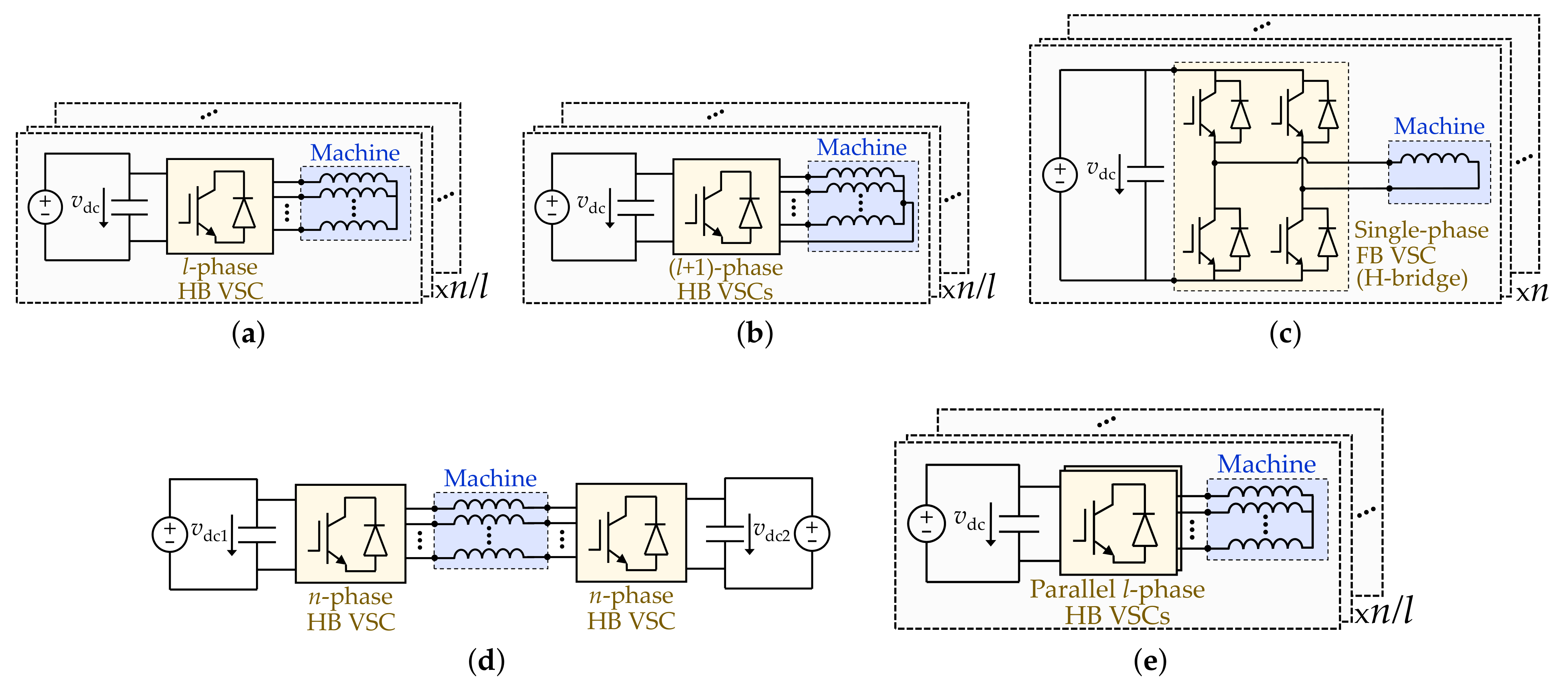
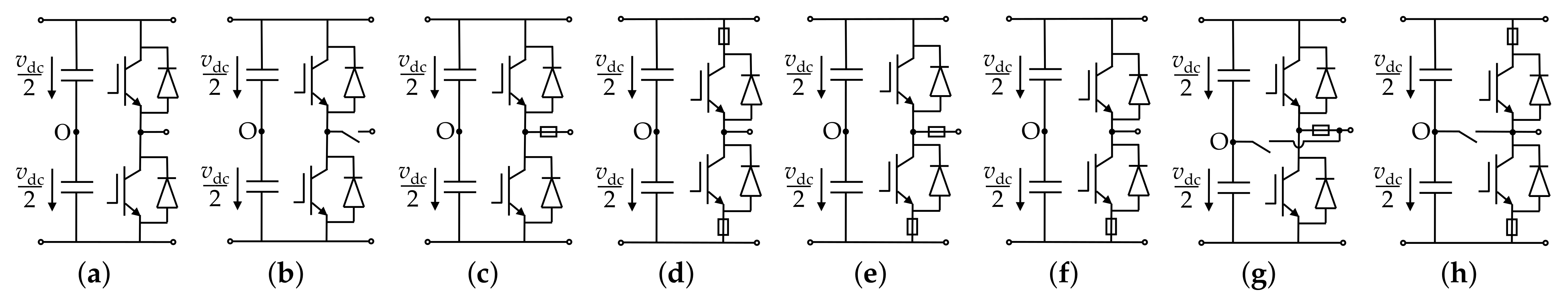
3.2. Types of Multiphase Voltage-Source-Converter (VSC) Topologies


| VSC Topology | Figure | n | References |
|---|---|---|---|
| Single n-phase HB diode rectifier | 8a * | 5 | [57,295,416] |
| Single n-phase HB diode rectifier | 8a * | 6 | [454] |
| Single n-phase HB VSC | 8a | − | Most of the others. |
| Single (n+1)-phase HB VSC | 8b | 5 | [361] |
| Single (n+)-phase HB VSC | 8c | 15 | [303] |
| Single n-phase FB VSC for open-end windings | 8d | 5 | [91,94,128,133,193,248,263,267,362,363,403,406] |
| Single n-phase FB VSC for open-end windings | 8d | 6 | [13,28,234,364,451] |
| Single n-phase FB VSC for open-end windings | 8d | 10 | [272] |
| Series dc-side connection of 3-phase HB diode rectifiers | 8e * | 6 | [417] |
| Series dc-side connection of 3-phase HB diode rectifiers | 8e * | 9 | [454] |
| Series dc-side connection of 3-phase HB VSCs | 8e | 9 | [409] |
| Series dc-side connection of 1-phase FB VSCs | 8f | − | [54] |
| Parallel 6-phase HB VSCs | 8g | 6 | [341] |
| Series dc-side connection of parallel 3-phase HB VSCs | 8h | 6 | [340] |
| Single n-phase T-type three-level VSC | 8i | 6 | [103,276,277,279] |
| Multiple independent 3-phase HB VSCs | 9a | 6 | [56,173,215,222,230,265,305,436] |
| Multiple independent 3-phase HB VSCs | 9a | 9 | [61,97,98,167,180,224,235,238,242,243,244,245,353,439,443] |
| Multiple independent 3-phase HB VSCs | 9a | 12 | [168] |
| Multiple independent 3-phase HB VSCs | 9a | 18 | [307] |
| Multiple independent 3-phase HB VSCs | 9a | 24 | [27] |
| Multiple independent (l+1)-phase HB VSCs | 9b | 6 | [346] |
| Multiple independent (l+1)-phase HB VSCs | 9b | 9 | [236] |
| Multiple independent 1-phase FB VSCs (H-bridges) | 9c | 4 | [165,228,266] |
| Multiple independent 1-phase FB VSCs (H-bridges) | 9c | 5 | [89,95,130,162,164,233,264,304] |
| Multiple independent 1-phase FB VSCs (H-bridges) | 9c | 6 | [93,96,99,210,211,212,223,227,240,265,271] |
| Dual n-phase HB VSC for open-end windings | 9d | 5 | [194,273] |
| Dual n-phase HB VSC for open-end windings | 9d | 6 | [220] |
| Multiple independent parallel 3-phase HB VSCs | 9e | 6 | [339,340] |
| 3-phase HB VSC + 3 phase FB VSC | − | 6 | [413] |
| 5-phase HB VSC + 5-phase HB diode rectifier | − | 10 | [405] |
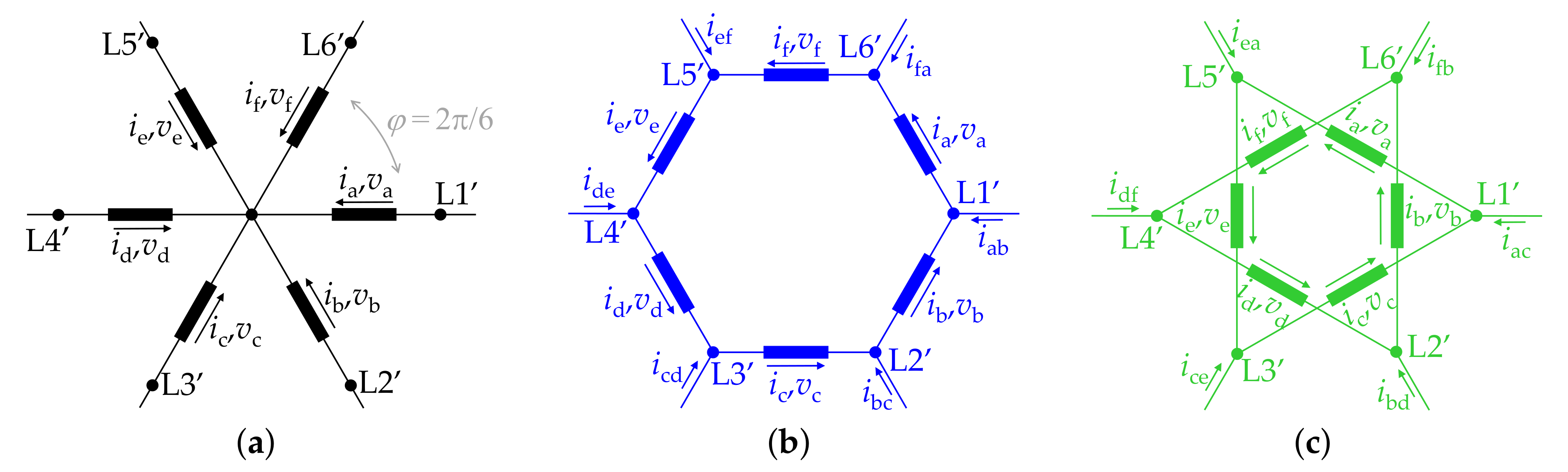
3.3. General Vector Space Decomposition (VSD) for Multiphase Drives
4. High-Resistance Connections

4.1. Causes of High-Resistance Connections
4.2. Detection of High-Resistance Connections
| References | Machine | Current Control | Monitored Signals | x-y Current Ref. | Finds Fault Location | Needs Extra * Sensors | Diagnoses Other Faults | Smooth Postfault Torque | ||
|---|---|---|---|---|---|---|---|---|---|---|
| n | WSA | Rotor | ||||||||
| Rossi et al. [65] | 6 | Asym. | SPMSM | - & x-y rotating PI | x-y voltage | 0 | No | No | No | Yes |
| Zarri et al. [66,67] | Odd | Sym. | IM | - & x-y rotating PI | - & x-y voltage | 0 | Phase | No | No | Yes |
| Tani et al. [68] | 5 | Sym. | SPMSM | - & x-y rotating PI | x-y voltage | 0 | Phase | No | Demagn. | Yes |
| Salas-Biedma et al. [69] | 5 | Sym. | IM | - DTC | - & x-y current | − | Phase | No | Phase OC | Yes |
| Farag et al. [62] | 6 | Sym. | IM | - & x-y current | - & x-y current | − | Phase | No | Ph. OC, bars | − |
| Chen et al. [59] | 5 | Sym. | SPMSM | - rotating PI | - & x-y current | − | Phase | No | No | No |
| Gonçalves et al. [63,64] | 6 | Asym. | SPMSM | - & x-y predictive | x-y current | Any | Phase | No | Phase OC | No |
| Hu et al. [61] | 9 | 3-sect. | PMaSynRM | Rotating PI per star | Zero-seq. voltage | 0 | Set | Voltage | Turn SC | No |
| Sun et al. [60] | Any | As./sym. | Any | - rot. PI & x-y PI | Phase dc voltage | dc | Phase | Voltage | Overheat. | No |
4.3. Tolerance to High-Resistance Connections
4.4. Concluding Remarks about High-Resistance Connections
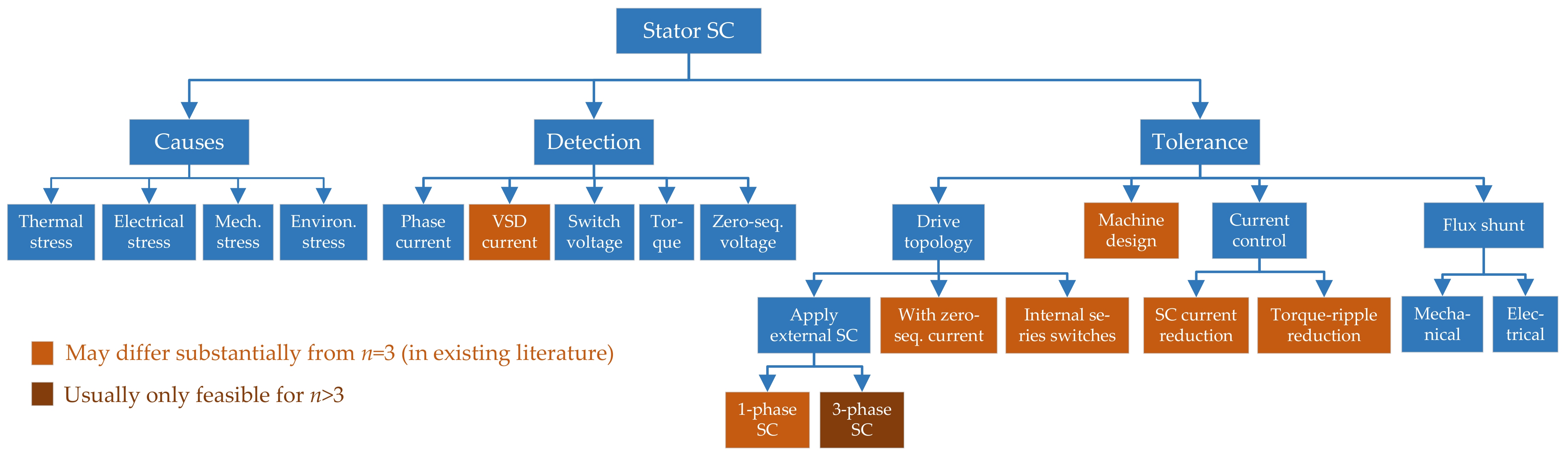
5. Stator SC Faults

5.1. Causes of Stator SC Faults
5.2. Detection of Stator SC Faults
| References | Machine | Types of Stator SCs | Identifies Location of SC | Monitored Signal/s | Extra Sensors * | Differs from | Robust to Other Faults | |||
|---|---|---|---|---|---|---|---|---|---|---|
| n | WSA | Rotor | FSCW | |||||||
| Jiang et al. [100] | 6 | Sym. | SPMSM | Yes | Phase | Phase | Ph. current | No | No | Phase OC |
| Jiang et al. [101] | 6 | Sym | SPMSM | Yes | Phase | Phase | Ph. current & neutral-point volt. | 1 volt. per star | No | No |
| Haylock et al. [93] | 6 | Sym. | SPMSM | Yes | Turn | Phase | Ph. current | No | No | No |
| Haylock et al. [99] | 6 | Sym. | SPMSM | Yes | Turn/ph. | Phase | Ph. current & on-state IGBT volt. | 1 volt. per IGBT | No | IGBT |
| Gritli et al. [88] | 6 | Asym. | SPMSM | No | Turn | No | x-y volt./curr. 1st/3rd harmonics | No | Yes | No |
| Immovilli et al. [89] | 5 | Sym. | SPMSM | Yes | Turn | Phase | Product - & x-y volt./current | No | Yes | Ecc., demag. |
| Cui et al. [94] | 5 | Sym. | IPMSM | Yes | Turn | No | Torque estimation error | Torque | No | No |
| Wu et al. [96] | 6 | Sym. | SPMSM | Yes | 1 turn | Ph., top/bot. | High-freq. ph. current (injected) | No | No | No |
| Sen et al. [90,92] | 5 | Sym. | SPMSM | Yes | Turn | Phase | PWM ripple ph. current | Analog circuit | No | No |
| Fan et al. [91] | 5 | Sym. | IPMSM | Yes | Turn | No | Zero-sequence current | No | Slightly | No |
| Wang et al. [97] | 9 | 3-sect. | PMaSynRM | No | Turn | Sector | Instant. active/reactive power | Yes | Slightly | No |
| Hu et al. [61] | 9 | 3-sect. | PMaSynRM | No | Turn | Phase | Zero-sequence voltage | 1 volt. per star | No | High-resist. |
5.3. Tolerance to Stator SC Faults
5.3.1. Drive Topologies
| References | Method Description | n | WSA | Splitting | VSC Topology | Figure | SC Types |
|---|---|---|---|---|---|---|---|
| Mecrow et al. [93,99,240] | 1-phase SC | 6 | Sym. | 1-phase | Independent H bridges | 9c | Turn |
| Arumugam et al. [223] | 1-phase SC & vertical winding | 6 | Sym. | 1-phase | Independent H bridges | 9c | Turn |
| Wang et al. [97,98,129,243,245] | 3-phase SC | 9 | Multisec. | 3-phase | Independent 3-phase HBs | 9a | Turn |
| Xu et al. [265] | 3-phase SC | 6 | Sym. | 3-phase | Independent 3-phase HBs | 9a | Phase |
| Arumugam et al. [222] | 3-phase SC & vertical winding | 6 | Sym. | 3-phase | Independent 3-phase HBs | 9a | Turn |
| Wang et al. [236] | 3-phase & neutral SC | 9 | Multisec. | 3-phase | Independent (l+1)-phase HBs | 9b | Turn |
| Shi et al. [270] | Delta connections | 9 | Multisec. | 3-phase | Independent 3-phase HBs | 9a | Turn |
| Various [94,248,263,267] | Zero-sequence control | 5 | Sym. | 1-phase | Single n-phase FB | 8d | Phase/turn |
| Guo et al. [128] | Zero-sequence control | 6 | Sym. | 1-phase | Single n-phase FB | 8d | Phase |
| Many | Zero-sequence control | − | − | 1-phase | Independent H bridges | 9c | Phase/turn |
| Jiang et al. [101] | Extra leg to neutrals & 0-seq. control | 6 | Sym. | 3-phase | Single (n+1)-phase HB + 2 switches | 12 | Phase |
| Si et al. [239] | Zero-sequence control | 4 | Sym. | 1-phase | Dual n-phase HB + 6 switches | 13 | Phase |
| Mohammadpour and Parsa [252] | Opening shorted phase | 5 | Sym. | No | Single n-phase HB | 8a | Phase |
5.3.1.1. Topology Reconfiguration for Applying Terminal SC
5.3.1.2. Topologies Allowing Reduction in Shorted-Turn Flux Linkage by Uncontrolled Zero-Sequence Current
5.3.1.3. Topologies Allowing Increase in DOFs by Controlled Zero-Sequence Current


5.3.1.4. Topologies Allowing Opening of a Shorted Phase
5.3.2. Machine Design
5.3.2.1. General Guidelines
- On the one hand, the self-inductance should be large, to limit the current in the affected phases so as to prevent excessive SCL and magnet demagnetization [225,230]. It can be designed so that the phase current is equal to rated in case of SC across the phase winding (1-p.u. self-inductance) [93,266,272], or even lower [258]. If the machine has saliency, this is especially important for the self-inductance in the axis, aligned with the back-EMF [240]. Furthermore, for limiting the SC current it is also recommendable to take into account the worst-case scenario (highest current) of turn fault in the machine design, while assuming that at least external SC (see Section 5.3.1.1) is applied to the affected phase/s to reduce the effect [167];
- On the other hand, the mutual inductance between phases should be very small, so that the voltage and current induced by the faulty phases in the healthy ones is minimized (magnetic decoupling).
| n | WSA | FSCW | Layers | Stator Slots | Coils/Phase | Rotor Poles | Splitting | Rotor Type | References |
|---|---|---|---|---|---|---|---|---|---|
| 4 | Sym. | Yes | Single | 8 | 1 | 6 | 1-phase | SPMSM | [228,266] |
| 4 | Sym. | Yes | Single | 8 | 1 | 10 | 1-phase | SPMSM | [163,165] |
| 4 | Sym. | Yes | Single | 8 | 1 | 12 | 1-phase | SPMSM | [239] |
| 5 | Sym. | No | Double | 15 | 3 | 4 | No | IPMSM | [251,252] |
| 5 | Sym. | No | Single | 40 | 8 | 4 | No | IM | [253] |
| 5 | Sym. | Yes | Double | 10 | 2 | 8 | No | SPMSM | [234] |
| 5 | Sym. | Yes | Double | 20 | 4 | 18 | No | SPMSM | [254] |
| 5 | Sym. | Yes | Hybrid | 10 | 2 | 12 | 1-phase | IPMSM | [267] |
| 5 | Sym. | Yes | Hybrid | 40 | 4 | 44 | No | Dual-rotor SPMSM | [249] |
| 5 | Sym. | Yes | Single | - | - | 10 | 1-phase | SPMSM | [268] |
| 5 * | Sym. | Yes | Single | 10 | 1 | 8 | 1-phase | Dual-rotor SPMSM | [272] |
| 5 | Sym. | Yes | Single | 10 | 1 | 8 | 1-phase | SPMSM | [165,241] |
| 5 | Sym. | Yes | Single | 10 | 1 | 12 | 1-phase | SPMSM | [95,162,163,164,165] |
| 5 | Sym. | Yes | Single | 10 | 1 | 12 | No | SPMSM | [166] |
| 5 | Sym. | Yes | Single | 20 | 2 | 18 | 1-phase | IPMSM | [248,263] |
| 5 | Sym. | Yes | Single | 20 | 2 | 18 | 1-phase | SPMSM | [130,233] |
| 5 | Sym. | Yes | Single | 20 | 2 | 18 | No | Outer-rotor IPMSM | [250] |
| 5 | Sym. | Yes | Single | 20 | 2 | 18 | − | IPMSM | [209] |
| 5 | Sym. | Yes | Single | 20 | 2 | 22 | No | Outer-rotor IPMSM | [250,255,256,257] |
| 5 | Sym. | Yes | Single | 40 | 4 | 28 | 1-phase | SPMSM | [226,227] |
| 5 | Sym. | Yes | Single | 40 | 4 | 42 | 1-phase | Outer-rotor IPMSM | [264] |
| 6 | 2-sector | No | Double | 36 | 6 | 8 | 3-phase | SynRM | [247] |
| 6 | 2-sector | No | Double | 48 | 2 | 4 | 3-phase | IM | [261] |
| 6 | 2-sector | Yes | Double | 12 | 2 | 10 | 3-phase | IPMSM/SPMSM | [258,259] |
| 6 | 2-sector | Yes | Double | 18 | 3 | 12 | 3-phase | SPMSM | [246] |
| 6 | 2-sector | Yes | Single | 12 | 1 | 10 | 3-phase | IPMSM/SPMSM | [258] |
| 6 | 4-sector | No | Double | 36 | 6 | 8 | 3-phase | SynRM | [247] |
| 6 | 2-sector | No | Double | 48 | 2 | 4 | 3-phase | IM | [261] |
| 6 | 4-sector | No | Single | 24 | 2 | 8 | 3-phase | SPMSM | [230] |
| 6 | Asym. | No | Double | 18 | 3 | 8 | 3-phase | IPMSM | [28,176,177,477] |
| 6 | Asym. | No | Double | 36 | 2 | 8 | 3-phase | SynRM | [247] |
| 6 | Asym. | No | Double | 48 | 2 | 4 | 3-phase | IM | [261] |
| 6 | Asym. | Yes | Single | 24 | 2 | 22 | 1-phase | SPMSM | [96,220] |
| 6 | Asym. | Yes | Single | 24 | 2 | 22 | − | SPMSM | [225] |
| 6 | Asym./sym. | Yes | Single | 12 | 1 | 10 | 3-phase | IPMSM/SPMSM | [258] |
| 6 | Asym./sym. | Yes | Double | 12 | 2 | 10 | 3-phase | IPMSM/SPMSM | [258,259] |
| 6 | Sym. | No | Double | 48 | 2 | 4 | 1-phase | IM | [271] |
| 6 | Sym. | No | Double | 48 | 2 | 4 | 3-phase | IM | [261] |
| 6 | Sym. | Yes | Double | 24 | 4 | 28 | 3-phase | Outer-rotor SPMSM | [229] |
| 6 | Sym. | Yes | Single | 12 | 1 | 8 | 1-phase | SPMSM | [93,99,212,240] |
| 6 | Sym. | Yes | Single | 12 | 1 | 10 | 1-phase | SPMSM | [128,163,165,210,211,265] |
| 6 | Sym. | Yes | Single | 12 | 1 | 10 | 3-phase | SPMSM | [100,101,260] |
| 6 | Sym. | Yes | Single | 12 | 1 | 10 | 3-phase | SPMSM | [231] |
| 6 | Sym. | Yes | Single | 12 | 1 | 10 | − | Hybrid-excit. PMSM | [178] |
| 6 | Sym. | Yes | Single | 12 | 1 | 14 | 1-phase | SPMSM | [165,223] |
| 6 | Sym. | Yes | Single | 12 | 1 | 14 | 3-phase | SPMSM | [222] |
| 6 | Sym. | Yes | Single | 24 | 2 | 14 | − | IPMSM | [221] |
| 6 | Sym. | Yes | Single | 36 | 3 | 16 | 3-phase | SPMSM | [230] |
| 9 | 3-sector | No | Single | 36 | 2 | 6 | 3-phase | PMaSynRM | [97,98,129,167,224,235,236,237,238,242,243,244,245,270] |
| 9 | Sym. | No | Single | 54 | 1 | 6 | 3-phase | IM | [269] |
| 24 | 8-sector | Yes | Double | 72 | 3 | 64 | 3-phase | Outer-rotor SPMSM | [27] |
5.3.2.2. Chronological Overview
| WSA | * | 3-Phase OC | 1-Phase SC, 2-Phase OC | 3-Phase SC | ||||
|---|---|---|---|---|---|---|---|---|
| Radial Force | Torque Ripple | Maximum Torque | Torque Ripple | SC Current | Torque Ripple | SC Current | ||
| Symmetrical | Low | Low | Low | High | High | Low | Low | Low |
| Two-sector | Very low | High | Low | Low | High | Very low | High | Very low |
5.3.3. Current Control
| Reference | Machine | Special Current References | Current Controller | Salient Features |
|---|---|---|---|---|
| Mohammadpour and Parsa [252] | PMSM | In healthy phases, for reducing SC current | Hysteresis | General; large current |
| References | Machine | VSC Leg/s of Faulty ph. | Special Current References | Current Controller | Salient Features |
|---|---|---|---|---|---|
| Mitcham/Arumugam et al. [223,227] | PMSM | Switching | In faulty ph., 90 lagging back-EMF | − | Simple |
| Wu et al. [96] | Asym. 6-ph. SPMSM | Switching | with 1st and 3rd harmonics | − | 3rd harm. |
| Wang et al. [224] | 3×3-ph. PMaSynRM | Switching | In faulty set, for reducing SC current | − | 3-sector |
| Gerada et al. [253] | IM | Switching | Reduced | Hyst. or multiple PI | IM; idle |
5.3.3.1. Reduction in SC Current under Phase SC
5.3.3.2. Reduction in SC Current under Turn Fault
5.3.3.3. Reduction in Torque Ripple under Phase SC
| References | Machine | Special Current References | Current Controller | Salient Features |
|---|---|---|---|---|
| Ede et al. [163] | PMSM | MLS | − | − |
| Atallah/Wang et al. [164,165] | PMSM | MLS | − | Field-weakening |
| Sun et al. [162] | 5-ph. SPMSM | MLS | Multiple PI | Field-weakening |
| Bianchi et al. [254] | 5-ph. SPMSM | Cancel 2nd & 4th torque harms. | − | Simple; 3rd harm. |
| Mohammadpour et al. [251] | PMSM | Iterative learning control | Multiple PI | Robust |
| Xu et al. [265] | Sym. 6-ph. SPMSM | Robust speed control | Multiple PI | Robust; ripple |
| Guo et al. [272] | Dual 5-ph. SPMSM | Robust speed control | − | Robust |
| Mohammadpour & Parsa [252] | PMSM | MLS | Hysteresis | General; harms. |
| Wu et al. [220] | Asym. 6-ph. SPMSM | MLS | Hysteresis | 3rd harm. |
| Sen et al. [166] | PMSM | MLS | Per-ph. multi-resonant | Field-weak.; harms. |
| Zhou/Chen et al. [255,257] | 5-ph. IPMSM | − | Reduced VSD + PI + SC curr. FF | Fast; sensors; not robust |
| Zhou et al. [256] | 5-ph. IPMSM | − | DTC * + disturbance observer | Robust |
| Jiang et al. [101] | Sym. 6-ph. SPMSM | − | RFOC + modified SV PWM | Topology |
| Si et al. [239] | 4-ph. SPMSM | Constant torque (single solution) | − | Topology |
| Huang et al. [241] | 5-ph. SPMSM | Equal phase-current amplitudes | − | High torque; not MLS |
| Yin et al. [234] | 5-ph. SPMSM | No -axis current constraint | − | High torque; not MLS |
5.3.3.4. Reduction in Torque Ripple under Turn Fault
| References | Machine | VSC Leg/s of Faulty ph. | Special Current References | Current Controller | Salient Features |
|---|---|---|---|---|---|
| Mohammadpour and Parsa [252] | PMSM | Switching | MLS | Hysteresis | General; harms. |
| Wu et al. [96] | Asym. 6-ph. SPMSM | Terminal SC | MLS | Hysteresis | Low SC current |
| Cui et al. [94] | 5-ph. IPMSM | Switching | − | - PI + zero-seq. current FF | Fast |
| Fan et al. [248] | 5-ph. IPMSM | Open | − | Reduced VSD + PI + voltage FF | Fast; open leg |
5.3.4. Flux Shunt
5.4. Concluding Remarks about Stator SC Faults
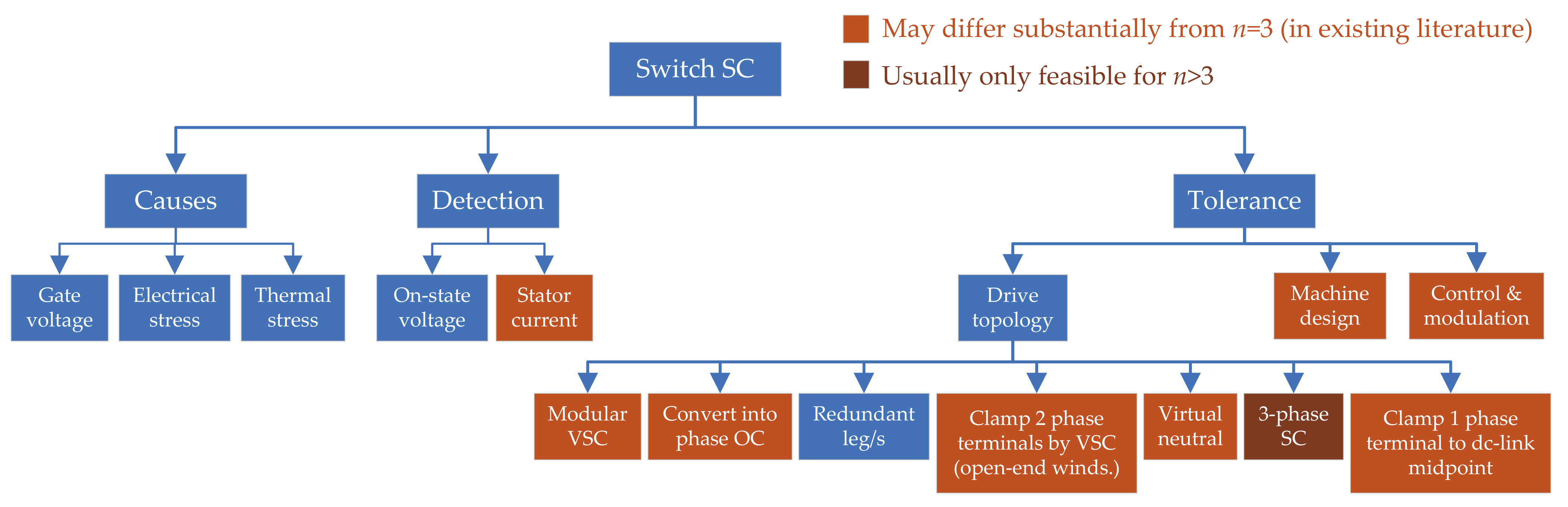
6. Switch SC Faults

6.1. Causes of Switch SC Faults
6.2. Detection of Switch SC Faults
6.3. Tolerance to Switch SC Faults
6.3.1. Drive Topologies
6.3.1.1. Increasing Isolation by VSC Modularity
| References | VSC Topology | Reconfiguration | Figure | Valid for H-Bridges | Special Machine | Torque Derating | Voltage * Derating |
|---|---|---|---|---|---|---|---|
| Many | Any + 1-4 fuses or 1 switch per line | Convert into phase OC | 15b–e | Yes | No | Yes | No |
| Kumar et al. [275] | Any + 1, n, legs & , switches | Replace faulty leg by redundant | − | Yes | No | No | No |
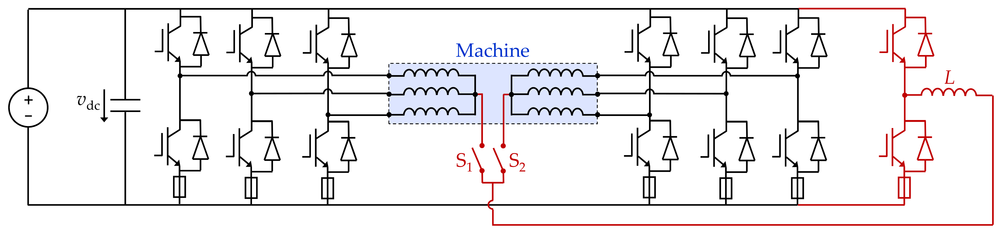
| Mecrow et al. [99,240] | One or multiple FBs | Clamp both terminals of stator ph. | 16 | Yes | Yes | Yes | Yes |
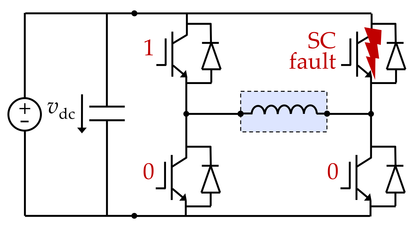
| Nguyen et al. [273] | Dual HB | Clamp both terminals of stator ph. | 17 | No | No | No | Yes |
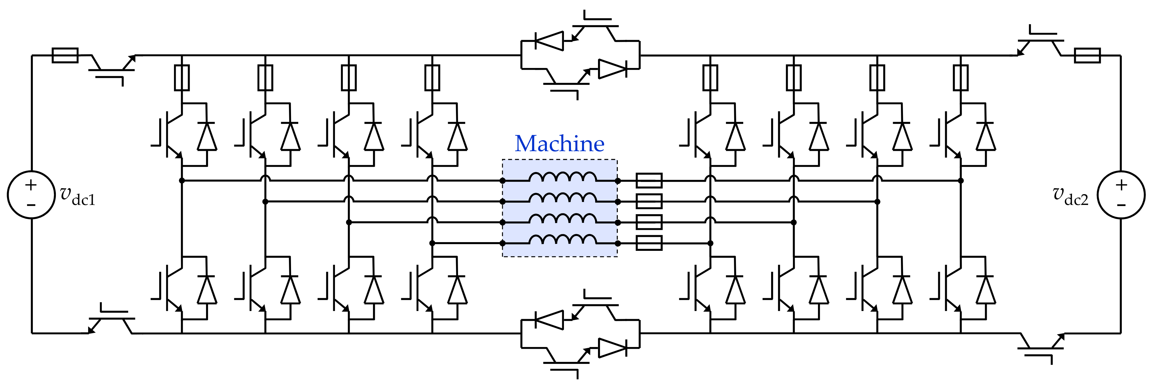
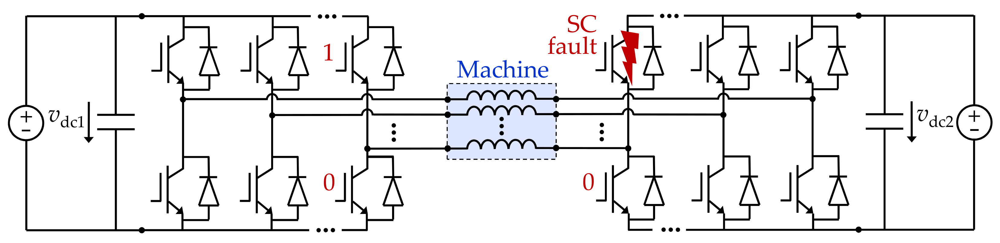
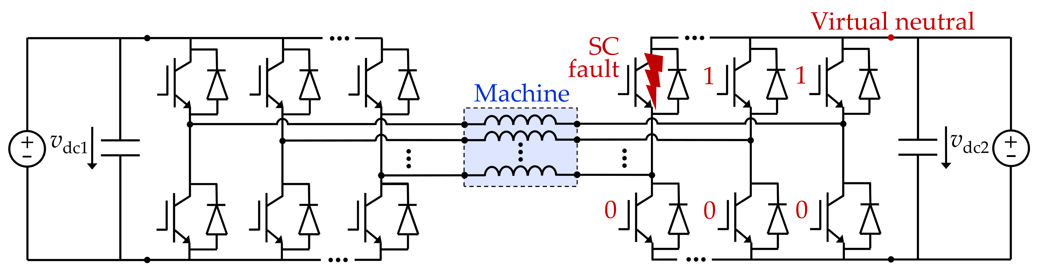
| Nguyen et al. [273] | Dual HB | Create virtual neutral point | 18 | No | No | No | Yes |
| Si et al. [239] | Dual HB + (2+3n) fuses & 6 switches | Create virtual neutral point | 13 | No | No | No | Yes |
| Reddy et al. [274] | HBs + 2 extra switches | Create virtual neutral point | − | No | No | No | Yes |
| Wang et al. [243,245] | HBs | Impose 3-phase SC | − | No | Yes | Yes | Yes |
| Wang et al. [103,277] | Any + 1,2 fuses & 1 switch per leg | Clamp terminal to dc-bus midpt. O | 15g,h | Yes | No | No | Yes |
| Yepes et al. [343] | Any + 1,2 fuses & 1 switch per leg | Alternate phase OC/clamping to O | 15g,h | Yes | No | If ↑ volt. | If ↑ torq. |
6.3.1.2. Conversion of Switch SC Fault into Phase OC

6.3.1.3. Redundant VSC Legs
6.3.1.4. Clamping Both Terminals of a Stator Phase through VSC


6.3.1.5. Creating Virtual Neutral Point through Dual HB VSCs

6.3.1.6. Applying Three-Phase SC through VSC
6.3.1.7. Allowing Current Flow through All Phases Avoiding Shorted Switches
6.3.2. Machine Design
6.3.3. Control and Modulation
6.4. Concluding Remarks about Switch SC Faults
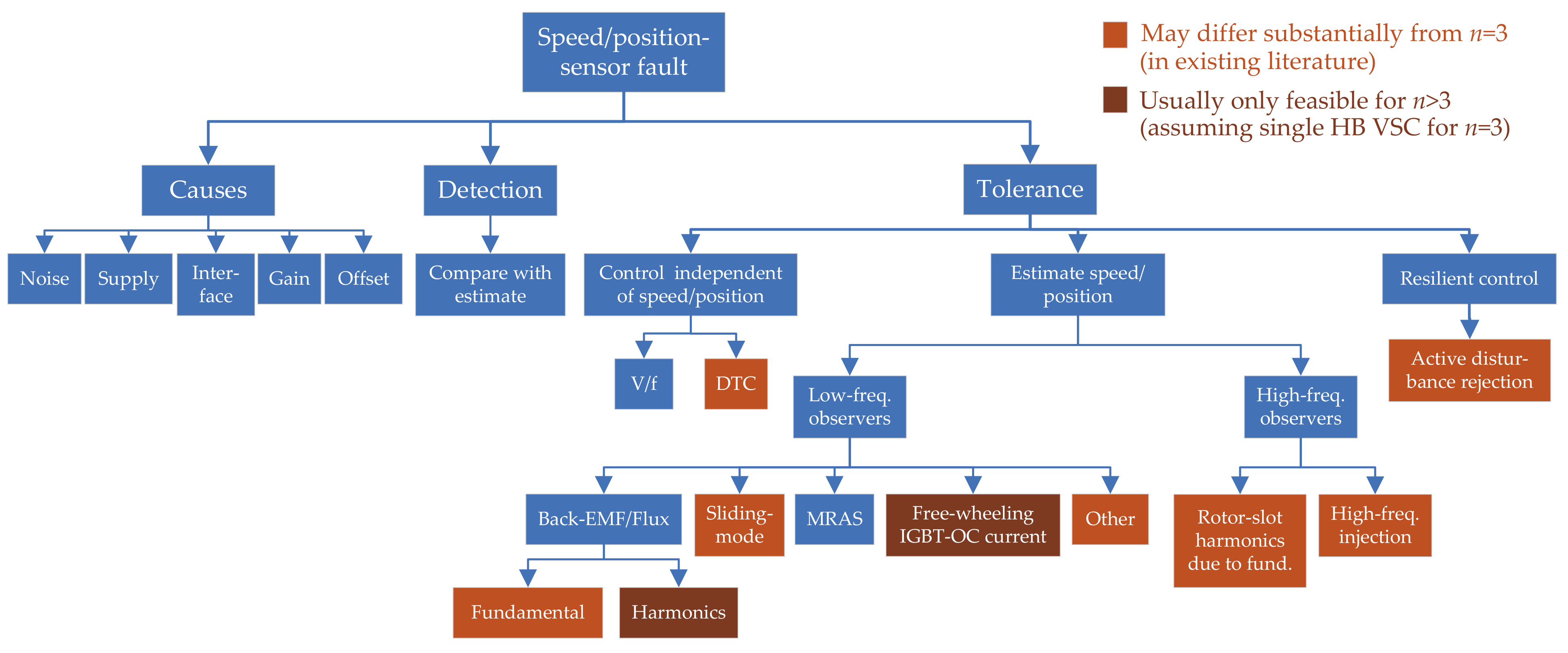
7. Speed/Position-Sensor Faults

7.1. Causes of Speed/Position-Sensor Faults
7.2. Detection of Speed/Position-Sensor Faults
7.3. Tolerance to Speed/Position-Sensor Faults
| References | Method Description | Machine | Differs from * | Proved to Work with Other Simult. Faults | Works at & Near 0 r/min | Extra Loss/Ripple | ||
|---|---|---|---|---|---|---|---|---|
| n | WSA | Rotor | ||||||
| Nguyen et al. [186] | Adaptive linear neural network | 5 | Sym. | PMSM | No | No | No | No |
| Olivieri et al. [130,187] | Back-EMF Luenberger observ. | 5 | Sym. | PMSM | No | No | No | No |
| Olivieri et al. [127] | Back-EMF Luenberger observ. (designed for ph. OC) | 5 | Sym. | PMSM | Yes | Phase OC | No | No |
| Xu et al. [210,211] | Back-EMF non-orthog. observ. (2 arbitrary phases) | 6 | Sym. | PMSM | Yes | Stator SC/OC | No | No |
| Imai et al. [196] | Back-EMF disturb. observ. (extended for saliency) | 9 | Multisec. | PMSM | Yes | No | No | No |
| Belie et al. [217] | Back-EMF 3rd-harm. observ. (PMSM with ph. OCs) | 5 | Sym. | PMSM | Yes | Phase OC | No | No |
| Stiscia et al. [198] | Back-EMF 3rd-harm. observ. (healthy PMSM) | 9 | Sym. | PMSM | Yes | No | No | No |
| Slunjski et al. [199] | Back-EMF 5th-harm. observ. (healthy PMSM) | 9 | Sym. | PMSM | Yes | No | No | No |
| Taheri et al. [206,207] | Extended Kalman filter | 6 | Asym. | IM | Yes | No | No | No |
| Tian et al. [216] | Free-wheeling current under IGBT fault | 5 | Sym. | PMSM | Yes | Switch OC | No | No |
| Zhang et al. [209] | High-freq. inject. (flux-intensifying PMSM) | 5 | Sym. | PMSM | No | No | Yes | Yes |
| Liu et al. [201] | High-freq. inject. ( square wave) | 5 | Sym. | PMSM | Yes | No | Yes | Yes |
| Tian et al. [208] | High-freq. inject. (system delay & stator resistance) | 5 | Sym. | PMSM | Yes | No | Yes | Yes |
| Barcaro et al. [215] | High-freq. inject. (various stator configs.) | 6 | As./sym./mul. | PMSM | No | Phase OC | Yes | Yes |
| Almarhoon et al. [191] | High-freq. inject. (stat. frame inject.; 0-seq. meas.) | 6 | Asym. | PMSM | Yes | No | Yes | Yes |
| Almarhoon et al. [192] | High-freq. inject. (synch. frame inject.; 0-seq. meas.) | 6 | Asym. | PMSM | Yes | No | Yes | Yes |
| Imai et al. [195] | High-freq. inject. (standstill; SPMSM) | 9 | Multisec. | PMSM | Yes | No | Yes | Yes |
| Ramezani et al. [188] | High-freq. inject. (- rotating sine wave) | 9 | Sym. | PMSM | Yes | No | Yes | Yes |
| Guzman et al. [181] | Minimization of torque error | 5 | Sym. | PMSM | No | No | No | No |
| Khadar et al. [193] | MRAS (flux-based; + parameter estimation) | 5 | Sym. | IM | No | No | No | No |
| Khadar et al. [194] | MRAS (sliding mode; + parameter estimation) | 5 | Sym. | IM | No | No | No | No |
| Holakooie et al. [204] | MRAS (sliding mode) | 6 | Asym. | IM | No | No | No | No |
| Holakooie et al. [205] | MRAS (sliding mode; + rotor-time-constant est.) | 6 | Asym. | IM | No | No | No | No |
| Listwan et al. [197] | MRAS (flux-based and current¤t-based) | 7 | Sym. | IM | No | No | No | No |
| Hezzi et al. [182] | Resilient control based on active dist. rejection | 5 | Sym. | PMSM | Yes | No | No | No |
| Amin et al. [203] | Rotor-flux robust simplified dynamic observer | 6 | Asym. | IM | No | No | No | No |
| Mengoni et al. [183] | Rotor-flux 3rd-harm. observ. (healthy IM) | 7 | Sym. | IM | Yes | No | No | Yes |
| Mengoni et al. [184,185] | Rotor-flux 3rd-harm. observ. (healthy IM; ↓ speed) | 7 | Sym. | IM | Yes | No | Yes | Yes |
| Yepes et al. [202] | Rotor-slot harm. due to fund. current (healthy) | Any | Asym./sym. | IM | Yes | No | No | No |
| Yepes et al. [214] | Rotor-slot harm. due to fund. current (phase OC) | Any | Asym./sym. | IM | Yes | Phase OC | No | No |
| Kong et al. [218] | Sliding-mode observ. (+ stator-resist. estimation) | 5 | Sym. | IM | Yes | Phase OC | No | No |
| Mossa et al. [189] | Sliding-mode observ. (+ rotor-resist. estimation) | 5 | Sym. | IM | Yes | No | No | No |
| Zhang et al. [219] | Sliding-mode observ. (volt. FF; active resist.) | 5 | Sym. | PMSM | No | Phase OC | No | No |
| Bensalem et al. [86] | Sliding-mode observ. (including 3rd space harm.) | 5 | Sym. | PMSM | Yes | No | No | No |
| Geng et al. [213] | Sliding-mode observ. (reduced-order transf.) | 6 | Asym. | IM | Yes | Phase OC | No | No |
| Xiao et al. [87] | Sliding-mode observ. (load-torque est. & rejection) | 6 | Asym. | PMSM | No | No | No | No |
| Zheng et al. [190] | St.-flux variable-structure observ. | 5 | Asym. | IM | No | No | No | No |
| Parsa et al. [200] | St.-flux volt.-model observ. (load angle included) | 5 | Sym. | PMSM | No | No | No | No |
| Green et al. [212] | St.-flux volt.-model observ. (per phase) | 6 | Sym. | PMSM | Yes | Stator SC/OC | No | No |
| Wang et al. [58] | St.-flux volt.-model observ. (= st.-flux & rotor freqs.) | 6 | Asym. | PMSM | No | No | No | No |
| Bojoi et al. [161] | St.-flux Gopinath observ. (fault: ignore rotor model) | 6 | Asym. | IM | Yes | Phase OC | No | No |
7.3.1. Encoderless Low-Frequency Observers
7.3.1.1. Stator-Flux Fundamental Observers
7.3.1.2. Rotor-Flux Fundamental Observers
7.3.1.3. Back-EMF Fundamental Observers
7.3.1.4. Rotor-Flux Harmonic Observers
7.3.1.5. Back-EMF Harmonic Observers
7.3.1.6. Sliding-Mode Observers
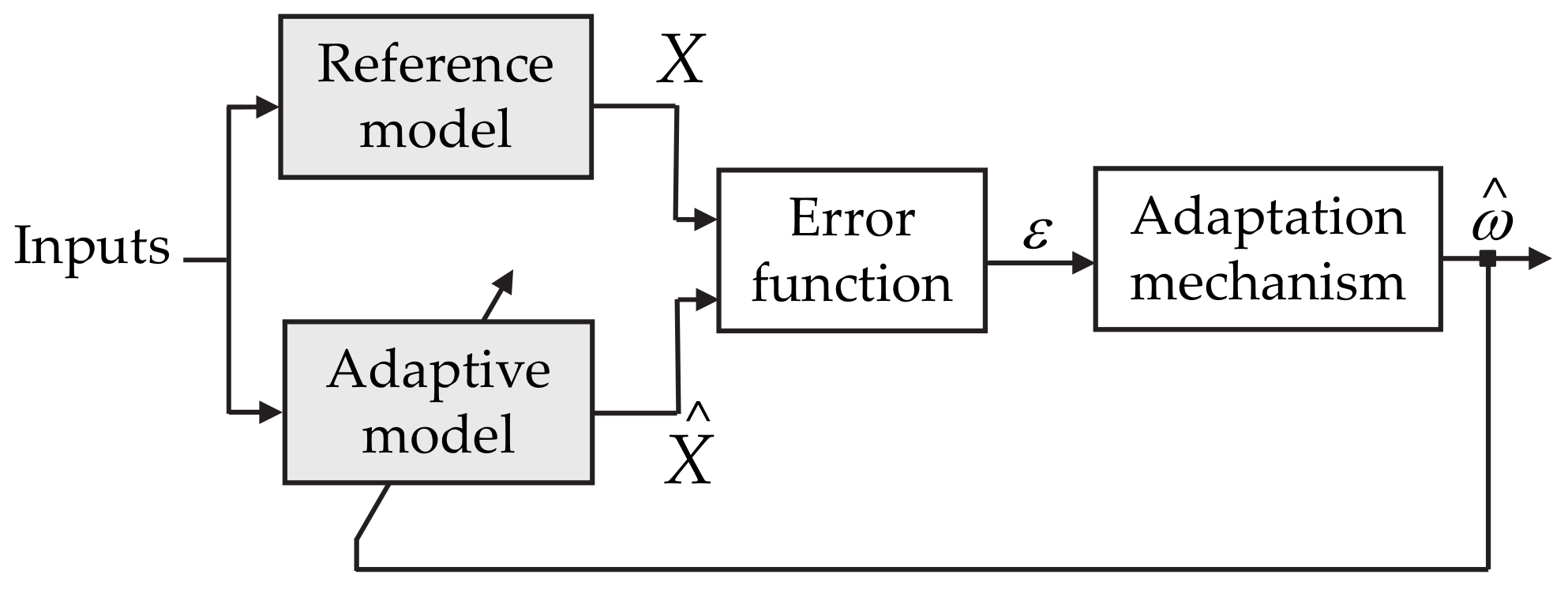
7.3.1.7. Model Reference Adaptive Systems (MRASs)

| References | Machine | Reference Model | Adaptive Model | Model Output | Adapted Parameter | ||
|---|---|---|---|---|---|---|---|
| n | WSA | Rotor | |||||
| Khadar et al. [193] | 5 | Sym. | IM | Conventional voltage model | Conventional current model | Rotor flux | Speed |
| Listwan and Pieńkowski [197] | 7 | Sym. | IM | Actual machine | Hybrid voltage-current model | Current | Speed |
| Holakooie et al. [204,205] | 6 | Asym. | IM | 2nd-order sliding-mode observer | Conventional current model | Rotor flux | Speed |
| Khadar et al. [194] | 5 | Sym. | IM | Sigmoid-based sliding-mode observer | Conventional current model | Rotor flux | Speed |
7.3.1.8. Free-Wheeling Current of OC IGBT
7.3.1.9. Other Low-Frequency Observers
7.3.2. Encoderless High-Frequency Observers
7.3.2.1. Based on Rotor-Slot Harmonics Due to Fundamental Current


7.3.2.2. High-Frequency Signal Injection
| References | Machine | Injected Signal | Measurement | ||
|---|---|---|---|---|---|
| n | WSA | Rotor | |||
| Zhang et al. [209] | 5 | Sym. | IPMSM | Rotating sine wave in - stat. frame | Negative-seq. - current |
| Ramezani and Ojo [188] | 9 | Sym. | IPMSM | Rotating sine wave in - stat. frame | - current harmonic |
| Almarhoon et al. [191] | 6 | Asym. | IPMSM | Rotating sine waves in double - stat. frames | Zero-seq. voltage |
| Barcaro et al. [215] | 6 | Asym./sym./mult. | IPMSM | Pulsating sine wave in axis | current harmonic |
| Imai et al. [195] | 9 | Multisec. | SPMSM | Pulsating sine wave in q axis of one sector | d axis of same sector |
| Almarhoon et al. [192] | 6 | Asym. | IPMSM | Pulsating sine waves in double d axes | Zero-seq. voltage |
| Liu et al. [201] | 5 | Sym. | IPMSM | Pulsating square wave in axis | - current harmonic |
| Tian et al. [208] | 5 | Sym. | IPMSM | Pulsating square/sine wave in axis | current harmonic |
7.3.3. Encoderless Resilient Control
7.4. Concluding Remarks about Speed/Position-Sensor Faults
- By setting to zero the current reference of a secondary plane of a PMSM with certain back-EMF harmonics, a back-EMF harmonic and its phase angle (rotor position) can easily be obtained from the respective voltage references without the need of machine parameters, such as inductances and resistances [198,199], unlike for ;
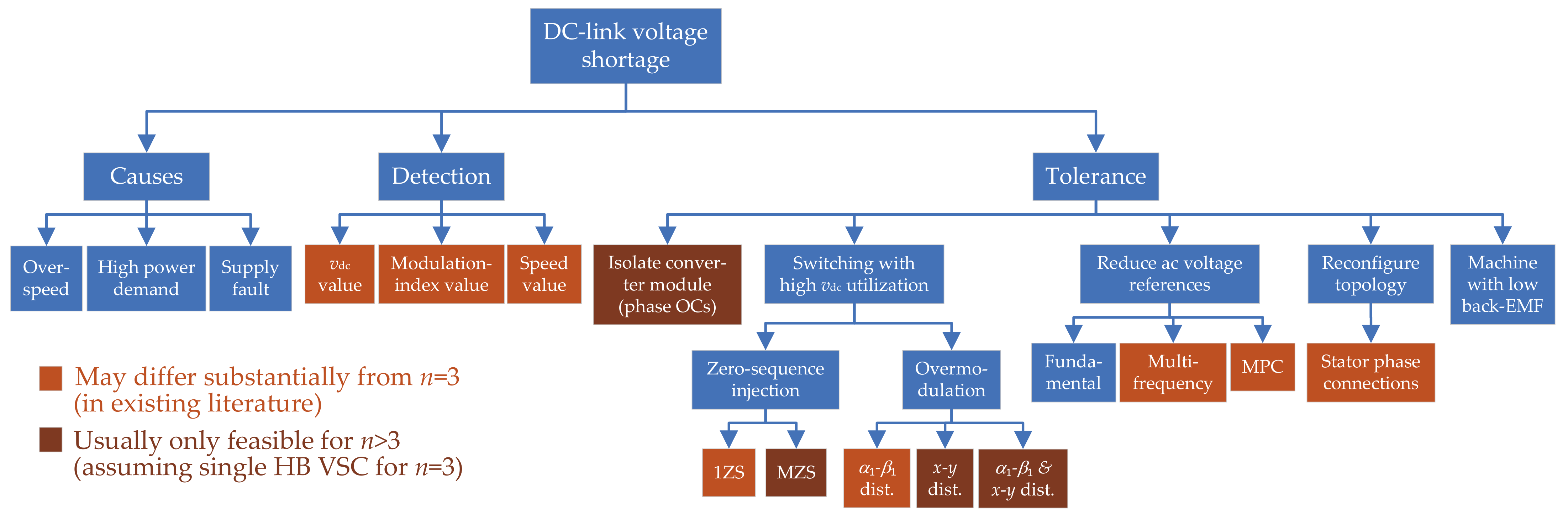
8. DC-Link Voltage Shortage
- If the modulation index increases beyond the linear modulation range, overmodulation occurs. This means that low-order voltage harmonics are introduced, the VSD subspaces become coupled in terms of voltage, and the conventional PWM and control methods are no longer able to work properly [8,9,134,135,137,138,139,142,143,145,147,148,149,150,151,152,154,155,156,158,159,167];

8.1. Causes of DC-Link Voltage Shortage
8.2. Detection of DC-Link Voltage Shortage
8.3. Tolerance to DC-Link Voltage Shortage
8.3.1. Isolation of VSC Module
8.3.2. Zero-Sequence Voltage Injection: 1ZS and MZS


8.3.3. Overmodulation
8.3.3.1. Square-Wave Switching and Passive x-y Filters

8.3.3.2. Combination of Passive x-y Filters and PWM
8.3.3.3. Overmodulation by Using PWM
| References | Method Description | n | WSA | VSC | Unneeded Dis-Tortion * | Minimum | Autom. i Limitation | Compu-Tational Complex. |
|---|---|---|---|---|---|---|---|---|
| Various [140,144,145] | Square-wave switching | Any | Any | HB | Yes | No | No | Very low |
| Various [146,148] | SV PWM with 2 large vectors | Any | Any | HB | No | No | No | Medium |
| Iqbal and Levi [148] | SV PWM with 2 large and 2 med. vectors | 5 | Sym. | HB | No | No | No | Medium |
| Carrasco and Silva [149] | SV PWM with min. | 5 | Sym. | HB | No | Yes | No | Very high |
| Duran et al. [151] | SV PWM with min. and no common mode | 5 | Sym. | HB | No | Yes | No | Very high |
| Prieto et al. [152] | SV PWM with low and no common mode | Odd | Sym. | HB | No | No | No | Very high |
| Bu et al. [159] | SV PWM with linear injection | 5 | Sym. | HB | No | No | No | Medium |
| Priestley et al. [133] | SV PWM for FB VSC | 5 | Sym. | FB | No | No | No | Very high |
| Yazdani et al. [156] | SV PWM with double 3-phase VSD | 6 | Asym. | HB | Yes | No | No | Very high |
| Zhu et al. [139] | SV PWM with double 3-phase VSD | 6 | Asym. | HB | Yes | No | No | High |
| Zhou et al. [154] | SV PWM with 6-phase VSD | 6 | Asym. | HB | No | Yes | No | Very high |
| Paul and Basu [157] | SV PWM with double 3-phase VSD (limited m) | 6 | Asym. | HB | No | Yes | No | High |
| Paul and Basu [158] | SV PWM with double 3-phase VSD (extended m) | 6 | Asym. | HB | No | Yes | No | High |
| Yang et al. [160] | SV PWM with sequential optimization scheme | Any | Sym. | HB | No | No | No | Very high |
| Yepes et al. [137] | CB PWM for multifrequency current control | Any | As./sym. | FB/HB | Yes | No | No | Low |
| Komrska et al. [155] | CB PWM with high utilization | Any | Sym. | HB | No | No | No | Medium |
| Yepes et al. [142,143] | Simple CB PWM with high utilization | Any | As./sym. | HB | No | No | No | Low |
| Vancini et al. [153] | CB PWM extended from | 5 | Sym. | HB | No | Yes | No | Low |
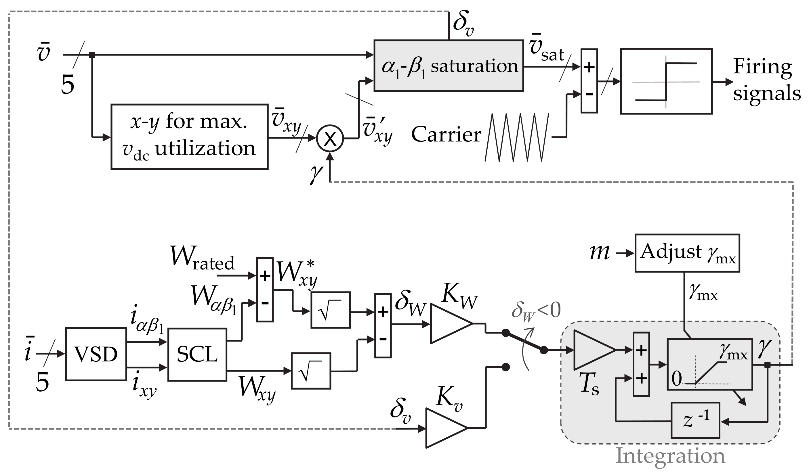
| Yepes et al. [138] | CB PWM with adaptive x-y current limitation | 5 | Sym. | HB | No | No | Yes | Medium |

8.3.3.4. Automatic x-y Current Limitation

8.3.3.5. Closed-Loop and Multifrequency Control under Overmodulation
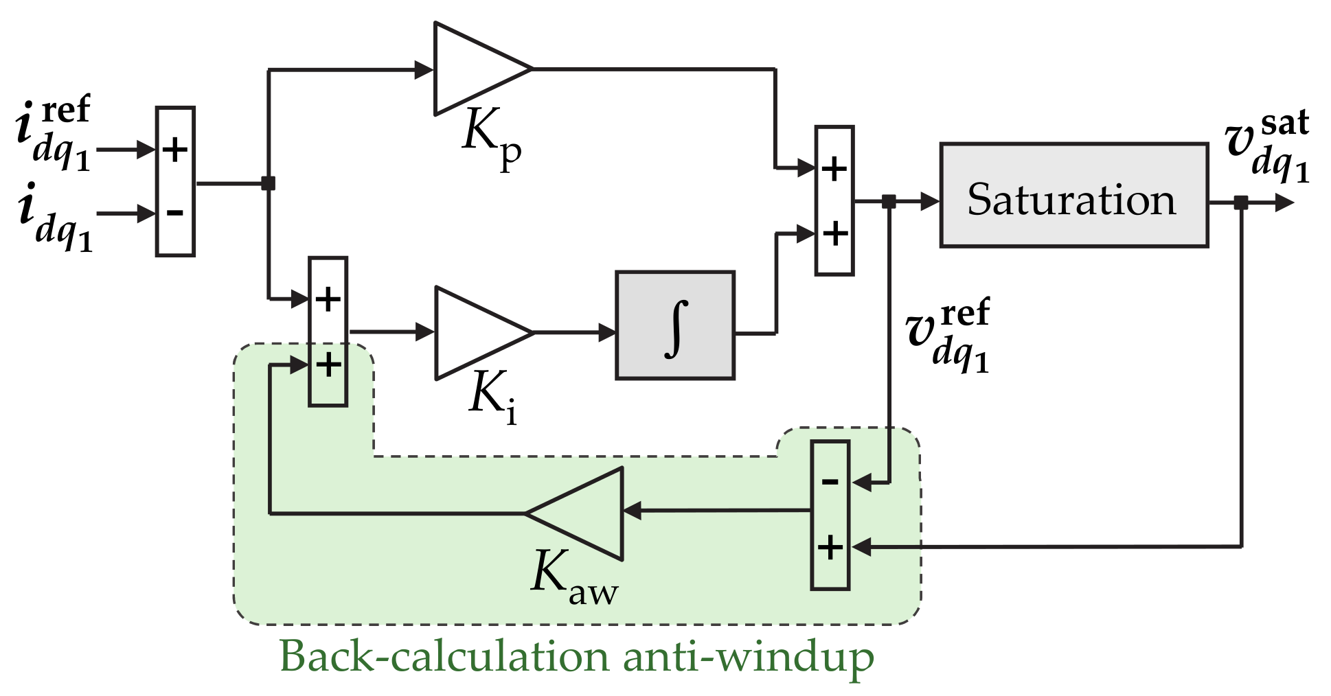
- Although open-loop control is reliable and simple [334], it is, in principle, only suitable for IMs, and its performance is usually inferior to closed-loop control in terms of efficiency, transient behavior, etc. Hence, closed-loop control is frequently preferred. However, during overmodulation, the actual low-frequency voltage components may differ to a great extent from the requested ones. That is, the plant seen by the current control (e.g., when using RFOC) becomes substantially non-linear. Consequently, in case of closed loop, the dynamics are likely to be worsened or even become unstable. In particular, saturating the output of a closed-loop linear controller with integral terms is known to cause unconstrained increase (wind-up) in the accumulated error in them [555,556]. In this manner, in a VSC with this type of control, the voltage reference tends to rise without limits when the actual ac voltage is saturated [557]. This increase aggravates the distortion associated with the output saturation, and it can also cause very long transient and large overshoot when the cause of saturation is eventually removed (e.g., recover) [556,557,558].
- As previously mentioned, most overmodulation algorithms assume that there is only - voltage reference. Non-zero voltage references are highly advisable in secondary subspaces where current can flow. This is mainly because, as a consequence of the corresponding low impedance, even small uncompensated voltage disturbances (due to dead times, asymmetries, saturation, back-EMF harmonics, etc.) give rise to large undesired currents [134,135,137,139,487,488,493,494]. Alternative reasons for including multifrequency (multi-subspace) voltages are, e.g., enhancing the torque density by harmonic injection [5,6,7,8,9,10] or driving several machines by a single VSC [2,10,12]. In any of these cases, the output of the multifrequency current control consists of non-zero voltage references in multiple subspaces and frequencies, so as to cancel the effect of the voltage disturbances and/or impose required currents.

8.3.4. Reducing AC Voltage References to Restore Linear Modulation in PWM-Based Control
8.3.4.1. Fundamental Frequency

8.3.4.2. Multifrequency Control for Disturbance Compensation


| References | n | WSA | Unneeded Fundamental Reduction | Depends on Relative Phase between Harmonics | Periodically Disables Harmonic Control | Needs Measurement |
|---|---|---|---|---|---|---|
| Yepes et al. [137] | Any | Asym./sym. | Yes | No | No | Yes |
| Karttunen et al. [135] | 6 | Asym. | No | Yes | Yes | Yes |
| Feng et al. [134] | 6 | Asym. | No | Yes | Yes | No |
8.3.4.3. Multifrequency Control for Enhancement of Torque Density

- (I)
- Both fundamental and third-order current components are exploited;
- (II)
- The third-order current harmonic is gradually reduced to avoid overmodulation;
- (III)
- Said harmonic is completely avoided, and field-weakening is applied to the fundamental if necessary;
- (IV)
- With available and field-weakening, it is no longer possible to provide maximum current, and, hence, the output power is reduced.
8.3.4.4. Multifrequency Control for other Applications
8.3.5. Consideration of Voltage Constraints in Current FCS-MPC
- In the first one, the optimum current references are obtained by minimizing a cost function involving the SCL and torque error, under the drive constraints: mainly the voltage (peak phase-to-phase voltage below ) and current (peak line current below switch maximum current) restrictions. Conversely to [7], which addresses a similar application with linear control (discussed in Section 8.3.4.3), the dc-link utilization is not unnecessarily reduced by simplifications in this regard. Furthermore, in this case the voltage constraint is taken into consideration in the optimization of the current references, unlike in [7];
- In the second stage, the cost function related to the squared current errors is minimized to find the optimum switching vectors.
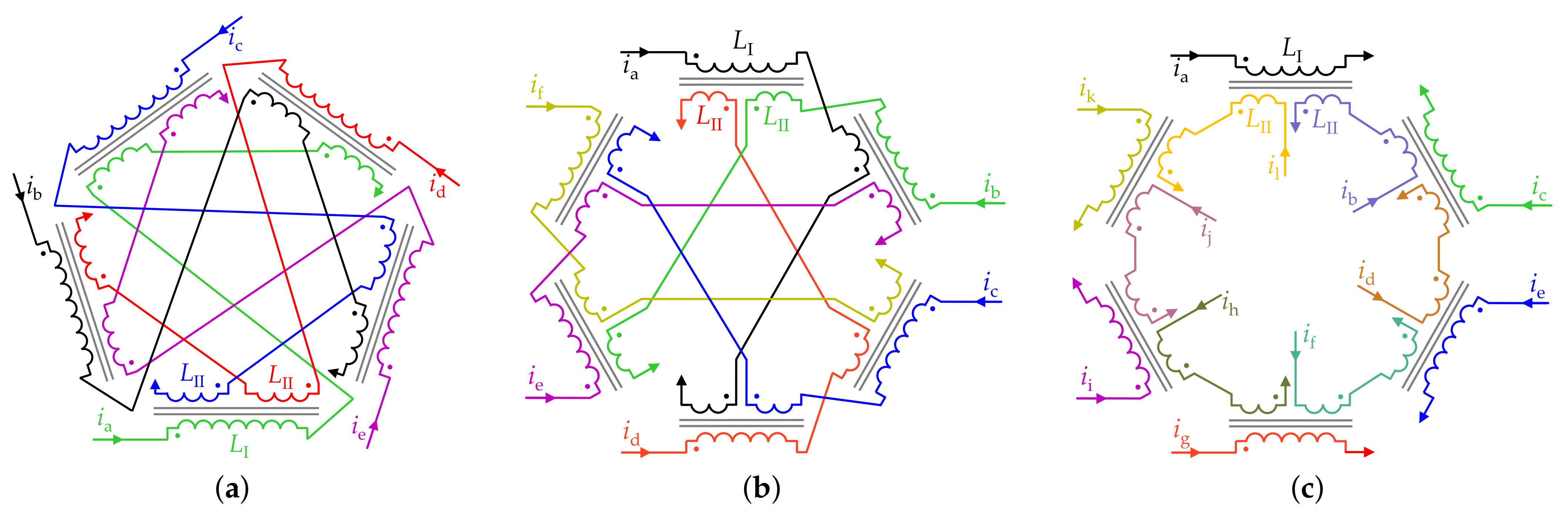
8.3.6. Reconfiguration of Stator Phase Connection

8.3.7. Tolerance to Uncontrolled Rectification by Machines with Low Back-EMF
8.4. Concluding Remarks about DC-Link Voltage Shortage
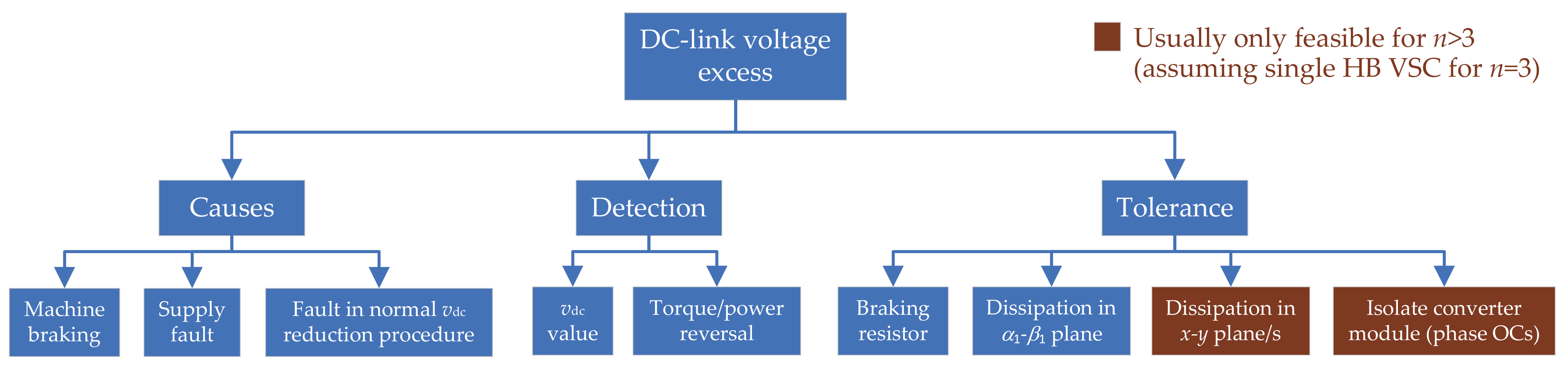
9. DC-Link Voltage Excess
9.1. Causes of DC-Link Voltage Excess

9.2. Detection of DC-Link Voltage Excess
9.3. Tolerance to DC-Link Voltage Excess
9.4. Concluding Remarks about DC-Link Voltage Excess
10. Machine-Cooling Faults
10.1. Causes of Machine-Cooling Faults

10.2. Detection of Machine-Cooling Faults
| References | Machine | x-y Injected Frequency | Causes Torque Ripple | Assumes Uniform Temperature | Estimated Temperature | Uses Extra Hardware | ||
|---|---|---|---|---|---|---|---|---|
| n | WSA | Rotor | ||||||
| Baneira et al. [70] | 6 | Asym. | IPMSM | dc | No | Yes | Stator winding | Yes |
| Sun et al. [60] | Any | Asym./sym. | Any | dc | No | No | Stator winding | Yes |
| Li et al. [71] | 6 | Asym. | IPMSM | Fund. | No | Yes | Stator winding | No |
| Feng et al. [72] | 6 | Asym. | IPMSM | Fund. | No | Yes | Magnets | No |
| Li et al. [73] | 6 | Asym. | IPMSM | Fund. | No | Yes | Magnets and winding | No |

10.3. Tolerance to Machine-Cooling Faults
10.4. Concluding Remarks about Machine-Cooling Faults
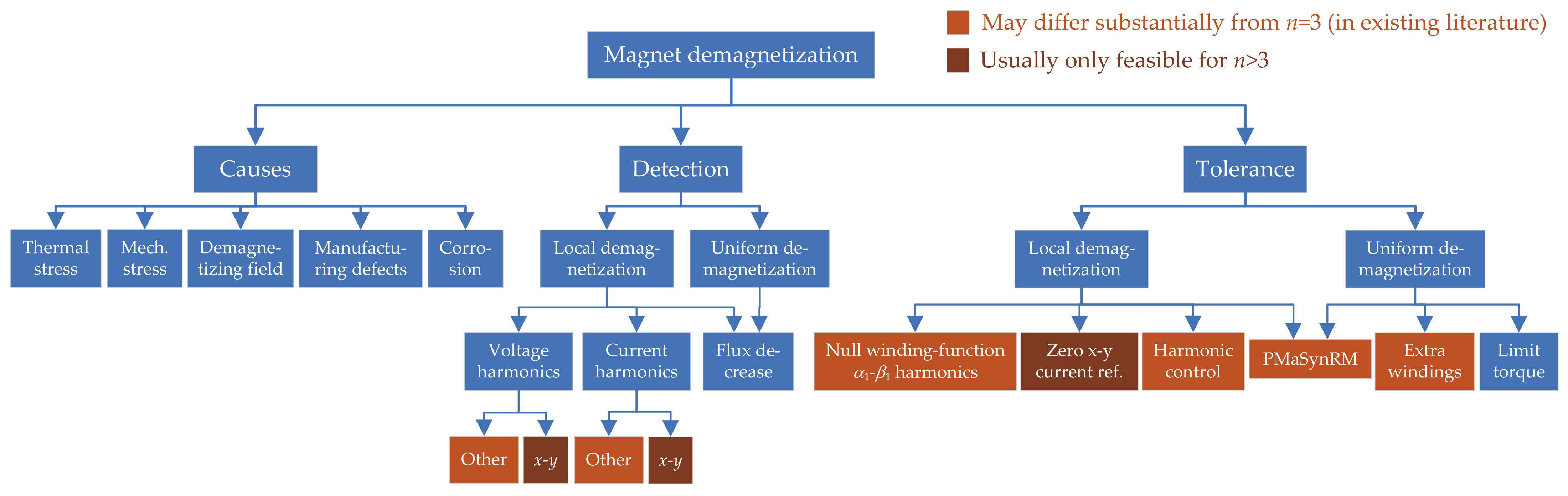
11. Permanent-Magnet Demagnetization

11.1. Causes of Permanent-Magnet Demagnetization
11.2. Detection of Permanent-Magnet Demagnetization
| References | Machine | Current Control with Zero Error at Monitored Harmonic | Monitored Harmonics | x-y Current Reference | Needs Extra * Sensors | Diagnoses Other Faults | Smooth Postfault Torque | ||
|---|---|---|---|---|---|---|---|---|---|
| n | WSA | Rotor | |||||||
| Gritli et al. [77,78] | 5 | Sym. | SPMSM | No | th x-y voltage/current | 0 | No | No | Yes |
| Casadei et al. [76] | 5 | Sym. | SPMSM | Yes | th x-y voltage | 0 | No | No | Yes |
| Tani et al. [68] | 5 | Sym. | SPMSM | Yes | th x-y voltage | 0 | No | High resist. | Yes |
| Mengoni et al. [74] | 6 | Asym. | SPMSM | Yes | 5th x-y voltage | 0 | No | No | Yes |
| Gritli et al. [75] | 6 | Asym. | SPMSM | Yes | 5th and th x-y voltage | 0 | No | No | Yes |
11.3. Tolerance to Permanent-Magnet Demagnetization
| References | Method Description | Reduces Torque Ripple Due to Local Demagnetization | Reduces Impact of Flux Decrease |
|---|---|---|---|
| Gritli et al. [74,75,78] | Null winding-function - harmonics | Yes | No |
| Gritli et al. [68,74,75,76,77,78] | Zero x-y current reference | Yes | No |
| Zhang et al. [178] | Extra windings | No | Yes |
| Wang et al. [129] | Adopt PMaSynRM | Yes | Yes |
11.4. Concluding Remarks about Permanent-Magnet Demagnetization
12. Other Types of Faults
12.1. DC-Link Capacitor Faults

| References | Topology | Figure | Tolerates Capacitor SC | Tolerates Capacitor OC | Tolerates Capacitor Aging | Tolerates Supply Fault |
|---|---|---|---|---|---|---|
| Various [27,130] | VSC modules with capacitors in parallel, using fuses | 40 | Yes | Partially | Partially | No |
| Wang et al. [129] | Independent VSC modules | 9a–c,e | Yes | Yes | Yes | Yes |
12.2. DC-Link Power-Supply Faults
| Topology | Figure | Performance Degradation | Refs. |
|---|---|---|---|
| Independent VSC modules | 9 | Torque derating | [25] |
| Dual HB + (2+3n) fuses and 6 switches | 13 | No | [239] |
12.3. DC-Link Voltage-Sensor Faults
12.4. Current-Sensor Faults
12.5. Control-Unit Faults
12.6. Mechanical Faults
12.6.1. Eccentricity
| References | Machine | Monitored Spectrum | Eccentricity | Needs Extra * Sensors | Differs from n = 3 | ||
|---|---|---|---|---|---|---|---|
| n | WSA | Rotor | |||||
| Andriamalala et al. [79] | 6 | Sym. | IM | Phase current/voltage | Mixed | No | No |
| Maouche et al. [80] | 6 | Sym. | IM | Voltage between neutrals | Static | 1 volt. | Yes |
| Choi et al. [84] | 5 | Sym. | PMaSynRM | Combined phase currents | Mixed | No | Yes |
| Malvar [604] | 5 | Sym. | IM | VSD current/voltage | Mixed | No | Yes |
12.6.2. Broken Rotor Bars
| References | Machine | Monitored Spectrum | Broken Bars | Needs Extra * Sensors | Differs from n = 3 | ||
|---|---|---|---|---|---|---|---|
| n | WSA | Rotor | |||||
| Maouche et al. [82] | 6 | Asym./sym. | IM | Phase current or torque | 1 | No | Yes |
| Maouche et al. [83] | 6 | Asym. | IM | Phase current | 1 | No | Yes |
| Abdel-Mageed et al. [85] | 6 | Asym. | IM | Phase current (neural network) | 1, 2 | No | Yes |
| Farag et al. [62] | 6 | Sym. | IM | - or phase current | 1, 2, 3 | No | No |
12.6.3. Bearing Faults
12.7. Concluding Remarks about Other Types of Faults
13. Comparison of Drive Topologies Considering Multiple Fault Types
- Better signal-to-noise ratio [84] and discrimination between faults [604] for diagnosis based on stator current (see, e.g., Section 12.6.1);
- Some current DOFs may give rise to significant uncontrolled current if, after a switch SC, current can still flow through the corresponding path but it is not controllable (no longer a DOF), e.g., the zero-sequence current in FB VSCs (see Section 6.3.1.4) [273];
- Drive non-idealities, such as undesired asymmetries and harmonics can cause troublesome current components through these DOFs, either at low or high frequencies, worsening torque pulsation and efficiency even in healthy operation unless special measures are taken (e.g., specific control, extra inductors, etc.) [101,488];
| VSC Topology | Stator Splitting | Figure | Stator Current DOFs | ||||
|---|---|---|---|---|---|---|---|
| Healthy Drive | Phase OCs or Terminal SCs | OC legs ( Parallel Pairwise) | Supply Faults | Capacitor Faults | |||
| Single n-phase HB VSC | No | 8a | 0 | 0 | |||
| Single n-phase HB VSC | l-phase | − | 0 | 0 | |||
| Single (n+1)-phase HB VSC | No | 8b | n | 0 | 0 | ||
| Single (n+)-phase HB VSC | l-phase | 8c | n | 0 | 0 | ||
| Single n-phase FB VSC | Single-ph. | 8d | n | 0 | 0 | ||
| Series dc-side connect. of l-phase HBs | l-phase | 8e | 0 | ||||
| Series dc-side connect. of H-bridges | Single-ph. | 8f | n | 0 | |||
| Parallel n-phase HB VSCs | No | 8g | 0 | 0 | |||
| Parallel n-phase HB VSCs | l-phase | − | 0 | 0 | |||
| Series dc-side connect. of parallel l-ph. HBs | l-phase | 8h | 0 | ||||
| Single n-phase T-type three-level VSC | No | 8i | 0 | 0 | |||
| Single n-phase T-type three-level VSC | l-phase | − | 0 | 0 | |||
| Multiple independent l-phase HBs | l-phase | 9a | |||||
| Multiple independent (l+1)-phase HBs | l-phase | 9b | n | ||||
| Multiple independent H-bridges | Single-ph. | 9c | n | ||||
| Dual n-phase HB VSC | Single-ph. | 9d | ;0 if | ;0 if | |||
| Multiple independent parallel l-ph. HBs | l-phase | 9e | |||||
| VSC Topology | Stator Splitting | Figure | Stator Current DOFs for Healthy Drive | Switch SCs (Different Legs and Phases) | ||
|---|---|---|---|---|---|---|
| Reconfiguration (cf. Section 6.3.1 | Stator Current DOFs | Uncontrolled Current Paths | ||||
| Single n-phase FB VSC | Single-ph. | 8d | n | Clamp both ph. terminals | ||
| Multiple independent H-bridges | Single-ph. | 9c | n | Clamp both ph. terminals | ||
| Dual n-phase HB VSC | Single-ph. | 9d | Clamp both ph. terminals | ; if | 0; if | |
| Dual n-phase HB VSC | Single-ph. | 9d | Virtual neutral * | 0 | ||
| VSC Topology | Stator Splitting | Figure | Stator Current DOFs | |||
|---|---|---|---|---|---|---|
| Healthy Drive | 1 OC Phase/leg or Terminal SC | 1 Supply Fault | 1 Capacitor Fault | |||
| Single n-phase HB VSC | No | 8a | 5 | 3 | 0 | 0 |
| Single n-phase HB VSC | 3-phase | − | 3 | 2 | 0 | 0 |
| Single (n+1)-phase HB VSC | No | 8b | 6 | 5 | 0 | 0 |
| Single (n+)-phase HB VSC | 3-phase | 8c | 6 | 5 | 0 | 0 |
| Single n-phase FB VSC | Single-ph. | 8d | 6 | 5 | 0 | 0 |
| Series dc-side connect. of l-phase HBs | 3-phase | 8e | 4 | 4 | 0 | 2 |
| Series dc-side connect. of H-bridges | Single-ph. | 8f | 6 | 5 | 0 | 5 |
| Parallel n-phase HB VSCs | No | 8g | 5 | 5 | 0 | 0 |
| Parallel n-phase HB VSCs | 3-phase | − | 4 | 4 | 0 | 0 |
| Series dc-side connect. of parallel l-ph. HBs | 3-phase | 8h | 4 | 4 | 0 | 2 |
| Single n-phase T-type three-level VSC | No | 8i | 5 | 4 | 0 | 0 |
| Single n-phase T-type three-level VSC | 3-phase | − | 4 | 3 | 0 | 0 |
| Multiple independent l-phase HBs | 3-phase | 9a | 4 | 3 | 2 | 2 |
| Multiple independent (l+1)-phase HBs | 3-phase | 9b | 6 | 5 | 3 | 3 |
| Multiple independent H-bridges | Single-ph. | 9c | 6 | 5 | 5 | 5 |
| Dual n-phase HB VSC | Single-ph. | 9d | 5 | 4 | 5 | 5 |
| Multiple independent parallel l-ph. HBs | 3-phase | 9e | 4 | 4 | 2 | 2 |
| VSC Topology | Stator Splitting | Figure | Stator Current DOFs for Healthy Drive | 1 Switch SC | ||
|---|---|---|---|---|---|---|
| Reconfiguration (cf. Section 6.3.1 | Stator Current DOFs | Uncontrolled Current Paths | ||||
| Single n-phase FB VSC | Single-ph. | 8d | n | Clamp both ph. terminals | 1 | |
| Multiple independent H-bridges | Single-ph. | 9c | n | Clamp both ph. terminals | 1 | |
| Dual n-phase HB VSC | Single-ph. | 9d | Clamp both ph. terminals | 0 | ||
| Dual n-phase HB VSC | Single-ph. | 9d | Virtual neutral | 0 | ||
- In topologies not based on open-end windings, increasing the modularity and isolation of the machine stator by splitting the windings into sets of fewer phases (e.g., 3-phase sets) results in reduced current DOFs and hence worse tolerance to the aforesaid fault types;
- Adopting FB VSCs such as independent H-bridges in order to attain high modularity can be counterproductive for non-isolated switch SC failures, where the uncontrolled zero-sequence paths are excited leading to increased SC current;
- The extra current DOFs provided by H-bridges tend to exhibit undesired currents due to non-idealities, even for healthy drive;
- H-bridges imply inferior dc-link utilization, and, thus, lower tolerance to faults that mean reduced dc-bus voltage/s.
14. Conclusions
Author Contributions
Funding
Institutional Review Board Statement
Informed Consent Statement
Acknowledgments
Conflicts of Interest
Abbreviations
| 1ZS | One zero sequence |
| CB | Carrier-based |
| DOF | Degree of freedom |
| DTC | Direct torque control |
| EMF | Electromotive force |
| FB | Full-bridge |
| FCS-MPC | Finite-control-set model predictive control |
| FF | Feed forward |
| flop | Floating-point operation |
| FRMLS | Full-range minimum-loss strategy |
| FSCW | Fractional-slot concentrated winding |
| HB | Half-bridge |
| IGBT | Insulated-gate bipolar transistor |
| IM | Induction machine |
| IPMSM | Interior permanent-magnet synchronous machine |
| MLS | Minimum-loss strategy |
| MPC | Model predictive control |
| MRAS | Model Reference Adaptive System |
| MTS | Maximum-torque strategy |
| MZS | Multiple zero sequence |
| OC | Open circuit |
| PI | Proportional-integral |
| PMaSynRM | Permanent-magnet-assisted synchronous reluctance machine |
| PMSM | Permanent-magnet synchronous machine |
| PWM | Pulsewidth modulation |
| RFOC | Rotor-field-oriented control |
| SC | Short circuit |
| SCL | Stator copper loss |
| SPMSM | Surface-mounted permanent-magnet synchronous machine |
| SV | Space vector |
| SynRM | Synchronous reluctance machine |
| THD | Total harmonic distortion |
| VSC | Voltage-source converter |
| VSD | Vector space decomposition |
| WFSM | Wound-field synchronous machine |
| WSA | Winding spatial arrangement |
| ZOH | Zero-order hold |
References
- Levi, E.; Bojoi, R.; Profumo, F.; Toliyat, H.A.; Williamson, S. Multiphase induction motor drives—A technology status review. IET Electric Power Appl. 2007, 1, 489–516. [Google Scholar] [CrossRef] [Green Version]
- Levi, E. Multiphase electric machines for variable-speed applications. IEEE Trans. Ind. Electron. 2008, 55, 1893–1909. [Google Scholar] [CrossRef]
- Tahaa, W.; Azerb, P.; Callegaro, A.D.; Emadi, A. Multiphase traction inverters: State-of-the-art review and future trends. IEEE Access 2022, 10, 4580–4599. [Google Scholar] [CrossRef]
- Levi, E. Advances in converter control and innovative exploitation of additional degrees of freedom for multiphase machines. IEEE Trans. Ind. Electron. 2016, 63, 433–448. [Google Scholar] [CrossRef] [Green Version]
- Abdel-Khalik, A.S.; Masoud, M.I.; Ahmed, S.; Massoud, A.M. Effect of current harmonic injection on constant rotor volume multiphase induction machine stators: A comparative study. IEEE Trans. Ind. Appl. 2012, 48, 2002–2013. [Google Scholar] [CrossRef]
- Abdel-Khalik, A.S.; Masoud, M.I.; Williams, B.W. Improved flux pattern with third harmonic injection for multiphase induction machines. IEEE Trans. Power Electron. 2012, 27, 1563–1578. [Google Scholar] [CrossRef]
- Mengoni, M.; Zarri, L.; Tani, A.; Parsa, L.; Serra, G.; Casadei, D. High-torque-density control of multiphase induction motor drives operating over a wide speed range. IEEE Trans. Ind. Electron. 2015, 62, 814–825. [Google Scholar] [CrossRef]
- Bermúdez, M.; Gomozov, O.; Kestelyn, X.; Barrero, F.; Nguyen, N.; Semail, E. Model predictive optimal control considering current and voltage limitations: Real-time validation using OPAL-RT technologies and five-phase permanent magnet synchronous machines. Math. Comput. Simul. 2019, 158, 148–161. [Google Scholar] [CrossRef] [Green Version]
- Bermúdez, M.; Martín, C.; Barrero, F.; Kestelyn, X. Predictive controller considering electrical constraints: A case example for five-phase induction machines. IET Electr. Power Appl. 2019, 13, 1079–1088. [Google Scholar] [CrossRef] [Green Version]
- Levi, E.; Dujic, D.; Jones, M.; Grandi, G. Analytical determination of dc-bus utilization limits in multiphase VSI supplied ac drives. IEEE Trans. Energy Convers. 2008, 23, 433–443. [Google Scholar] [CrossRef] [Green Version]
- Yepes, A.G.; Riveros, J.A.; Doval-Gandoy, J.; Barrero, F.; Lopez, O.; Bogado, B.; Jones, M.; Levi, E. Parameter identification of multiphase induction machines with distributed windings–Part 1: Sinusoidal excitation methods. IEEE Trans. Energy Convers. 2012, 27, 1056–1066. [Google Scholar] [CrossRef]
- Levi, E.; Jones, M.; Vukosavic, S.N.; Toliyat, H.A. A novel concept of a multiphase, multimotor vector controlled drive system supplied from a single voltage source inverter. IEEE Trans. Power Electron. 2004, 19, 320–335. [Google Scholar] [CrossRef]
- dos Santos Moraes, T.; Nguyen, N.K.; Semail, E.; Meinguet, F.; Guerin, M. Dual-multiphase motor drives for fault-tolerant applications: Power electronic structures and control strategies. IEEE Trans. Power Electron. 2018, 33, 572–580. [Google Scholar] [CrossRef] [Green Version]
- dos Santos Moraes, T.J.; Trabelsi, M.; Nguyen, N.K.; Semail, E.; Meinguet, F.; Guerin, M. Inverter open circuit faults diagnosis in series-connected six-phases permanent magnet drive. In Proceedings of the 2017 IEEE 11th International Symposium on Diagnostics for Electrical Machines, Power Electronics and Drives (SDEMPED), Tinos, Greece, 29 August–1 September 2017; pp. 188–194. [Google Scholar] [CrossRef] [Green Version]
- Gupta, N.; Gopika, T.G.; Kaarthik, R.S. Modeling and decoupled control of series-connected split-phase synchronous machines with open-circuit fault. IEEE Trans. Ind. Appl. 2020, 56, 325–334. [Google Scholar] [CrossRef]
- Subotic, I.; Bodo, N.; Levi, E.; Dumnic, B.; Milicevic, D.; Katic, V. Overview of fast on-board integrated battery chargers for electric vehicles based on multiphase machines and power electronics. IET Electr. Power Appl. 2016, 10, 217–229. [Google Scholar] [CrossRef]
- Subotic, I.; Bodo, N.; Levi, E.; Jones, M. Onboard integrated battery charger for EVs using an asymmetrical nine-phase machine. IEEE Trans. Ind. Electron. 2015, 62, 3285–3295. [Google Scholar] [CrossRef]
- Subotic, I.; Bodo, N.; Levi, E.; Jones, M.; Levi, V. Isolated chargers for EVs incorporating six-phase machines. IEEE Trans. Ind. Electron. 2016, 63, 653–664. [Google Scholar] [CrossRef] [Green Version]
- Subotic, I.; Bodo, N.; Levi, E. Single-phase on-board integrated battery chargers for EVs based on multiphase machines. IEEE Trans. Power Electron. 2016, 31, 6511–6523. [Google Scholar] [CrossRef] [Green Version]
- Subotic, I.; Bodo, N.; Levi, E. An EV drive-train with integrated fast charging capability. IEEE Trans. Power Electron. 2016, 31, 1461–1471. [Google Scholar] [CrossRef] [Green Version]
- Bodo, N.; Levi, E.; Subotic, I.; Espina, J.; Empringham, L.; Johnson, C.M. Efficiency evaluation of fully integrated on-board EV battery chargers with nine-phase machines. IEEE Trans. Energy Convers. 2017, 32, 257–266. [Google Scholar] [CrossRef]
- Abdel-Majeed, M.S.; Eldeeb, H.M.; Metwly, M.Y.; Abdel-Khalik, A.S.; Hamad, M.S.; Hamdy, R.A.; Ahmed, S. Postfault operation of onboard integrated battery charger via a nine-phase EV-drive train. IEEE Trans. Ind. Electron. 2021, 68, 5626–5637. [Google Scholar] [CrossRef]
- Sala, G.; Valente, G.; Formentini, A.; Papini, L.; Gerada, D.; Zanchetta, P.; Tani, A.; Gerada, C. Space vectors and pseudoinverse matrix methods for the radial force control in bearingless multisector permanent magnet machines. IEEE Trans. Ind. Electron. 2018, 65, 6912–6922. [Google Scholar] [CrossRef]
- Duran, M.; Barrero, F. Recent advances in the design, modeling and control of multiphase machines–Part 2. IEEE Trans. Ind. Electron. 2016, 63, 459–468. [Google Scholar] [CrossRef]
- Bennett, J.W.; Atkinson, G.J.; Mecrow, B.C.; Atkinson, D.J. Fault-tolerant design considerations and control strategies for aerospace drives. IEEE Trans. Ind. Electron. 2012, 59, 2049–2058. [Google Scholar] [CrossRef]
- Cao, W.; Mecrow, B.C.; Atkinson, G.J.; Bennett, J.W.; Atkinson, D.J. Overview of electric motor technologies used for more electric aircraft (MEA). IEEE Trans. Ind. Electron. 2012, 59, 3523–3531. [Google Scholar] [CrossRef]
- Ifedi, C.J.; Mecrow, B.C.; Brockway, S.T.M.; Boast, G.S.; Atkinson, G.J.; Kostic-Perovic, D. Fault-tolerant in-wheel motor topologies for high-performance electric vehicles. IEEE Trans. Ind. Appl. 2013, 49, 1249–1257. [Google Scholar] [CrossRef]
- Patel, V.I.; Wang, J.; Nugraha, D.T.; Vuletić, R.; Tousen, J. Enhanced availability of drivetrain through novel multiphase permanent-magnet machine drive. IEEE Trans. Ind. Electron. 2016, 63, 469–480. [Google Scholar] [CrossRef]
- Singh, G. Multi-phase induction machine drive research—A survey. Electr. Power Syst. Res. 2002, 61, 139–147. [Google Scholar] [CrossRef]
- Levi, E.; Jones, M. A literature survey of state-of-the art in multiphase ac drives. In Proceedings of the UPEC, Stafford, UK, 9–11 September 2002; pp. 505–510. [Google Scholar]
- Huang, J.; Kang, M.; Yang, J.; Jiang, H.; Liu, D. Multiphase machine theory and its applications. In Proceedings of the ICEMS, Wuhan, China, 17–20 October 2008; pp. 1–7. [Google Scholar]
- Liu, Z.; Li, Y.; Zheng, Z. A review of drive techniques for multiphase machines. CES Trans. Elect. Mach. Syst. 2018, 2, 243–251. [Google Scholar] [CrossRef]
- Gupta, S.K.; Singh, O.; Khan, M.A.; Kushwaha, A.K. A review on developments of polyphase machines. J. Inf. Optim. Sci. 2020, 41, 327–343. [Google Scholar] [CrossRef]
- Barrero, F.; Duran, M.J. Recent advances in the design, modeling and control of multiphase machines–Part 1. IEEE Trans. Ind. Electron. 2016, 63, 449–458. [Google Scholar] [CrossRef]
- Parsa, L. On advantages of multi-phase machines. In Proceedings of the 31st Annual Conference of IEEE Industrial Electronics Society, 2005. IECON 2005, Raleigh, NC, USA, 6–10 November 2005; pp. 1574–1579. [Google Scholar] [CrossRef]
- Parsa, L.; Toliyat, H.A. Five-phase permanent magnet motor drives for ship propulsion applications. In Proceedings of the IEEE Electric Ship Technologies Symposium, Philadelphia, PA, USA, 27 July 2005; pp. 371–378. [Google Scholar] [CrossRef]
- Zoric, I.; Zabaleta, M.; Jones, M.; Levi, E. Techniques for power sharing between winding sets of multiple three-phase machines. In Proceedings of the 2017 IEEE Workshop on Electrical Machines Design, Control and Diagnosis (WEMDCD), Nottingham, UK, 20–21 April 2017; pp. 208–215. [Google Scholar] [CrossRef]
- Casadei, D.; Serra, G.; Tani, A.; Zarri, L. Direct torque control for induction machines: A technology status review. In Proceedings of the 2013 IEEE Workshop on Electrical Machines Design, Control and Diagnosis (WEMDCD), Paris, France, 11–12 March 2013; pp. 117–129. [Google Scholar] [CrossRef]
- Tenconi, A.; Rubino, S.; Bojoi, R. Model predictive control for multiphase motor drives–A technology status review. In Proceedings of the 2018 International Power Electronics Conference (IPEC-Niigata 2018 -ECCE Asia), Niigata, Japan, 20–24 May 2018; pp. 732–739. [Google Scholar] [CrossRef]
- Gonçalves, P.; Cruz, S.; Mendes, A. Finite control set model predictive control of six-phase asymmetrical machines–An overview. Energies 2019, 12, 4693. [Google Scholar] [CrossRef] [Green Version]
- Bermudez, M.; Martín, C.; Gonzalez-Prieto, I.; Duran, M.J.; Arahal, M.R.; Barrero, F. Predictive current control in electrical drives: An illustrated review with case examples using a five-phase induction motor drive with distributed windings. IET Electric Power Appl. 2020, 14, 1291–1310. [Google Scholar] [CrossRef]
- Bojoi, R.; Farina, F.; Profumo, F.; Tenconi, A. Dual-three phase induction machine drives control–A survey. IEEJ Trans. Ind. Appl 2006, 126, 420–429. [Google Scholar] [CrossRef]
- Alosa, C.; Immovilli, F.; Lorenzani, E. Modular multi-three-phase electric drives for enhanced reliability and current ripple minimization. In Proceedings of the IECON 2019—45th Annual Conference of the IEEE Industrial Electronics Society, Lisbon, Portugal, 14–17 October 2019; pp. 7108–7114. [Google Scholar] [CrossRef]
- Oleschuk, V.; Grandi, G.; Dragonas, F.A. Five-phase and six-phase converters with synchronized PWM: An overview. In Proceedings of the 2011 IEEE International Symposium on Industrial Electronics, Gdansk, Poland, 27–30 June 2011; pp. 283–288. [Google Scholar] [CrossRef]
- Vu, D.T.; Nguyen, N.K.; Semail, E. An overview of methods using reduced-ordered transformation matrices for fault-tolerant control of 5-phase machines with an open phase. In Proceedings of the 2019 IEEE International Conference on Industrial Technology (ICIT), Melbourne, Australia, 13–15 February 2019; pp. 1557–1562. [Google Scholar] [CrossRef] [Green Version]
- Levi, E.; Bodo, N.; Dordevic, O.; Jones, M. Recent advances in power electronic converter control for multiphase drive systems. In Proceedings of the 2013 IEEE Workshop on Electrical Machines Design, Control and Diagnosis (WEMDCD), Paris, France, 11–12 March 2013; pp. 158–167. [Google Scholar] [CrossRef]
- Wang, Z.; Wang, X.; Wang, Y.; Chen, J.; Cheng, M. Fault tolerant control of multiphase multilevel motor drives–Technical review. Chin. J. Electr. Eng. 2017, 3, 76–86. [Google Scholar] [CrossRef]
- Salem, A.; Narimani, M. A review on multiphase drives for automotive traction applications. IEEE Trans. Transp. Electrific. 2019, 5, 1329–1348. [Google Scholar] [CrossRef]
- Bojoi, R.; Cavagnino, A.; Tenconi, A.; Tessarolo, A.; Vaschetto, S. Multiphase electrical machines and drives in the transportation electrification. In Proceedings of the 2015 IEEE 1st International Forum on Research and Technologies for Society and Industry Leveraging a better tomorrow (RTSI), Turin, Italy, 16–18 September 2015; pp. 205–212. [Google Scholar] [CrossRef]
- Bojoi, R.; Rubino, S.; Tenconi, A.; Vaschetto, S. Multiphase electrical machines and drives: A viable solution for energy generation and transportation electrification. In Proceedings of the 2016 International Conference and Exposition on Electrical and Power Engineering (EPE), Iasi, Romania, 20–22 October 2016; pp. 632–639. [Google Scholar] [CrossRef]
- Menon, R.; Kadam, A.H.; Azeez, N.A.; Williamson, S.S. A comprehensive survey on permanent magnet synchronous motor drive systems for electric transportation applications. In Proceedings of the IECON 2016—42nd Annual Conference of the IEEE Industrial Electronics Society, Florence, Italy, 23–26 October 2016; pp. 6627–6632. [Google Scholar] [CrossRef]
- Bojoi, R.; Neacsu, M.G.; Tenconi, A. Analysis and survey of multi-phase power electronic converter topologies for the more electric aircraft applications. In Proceedings of the International Symposium on Power Electronics Power Electronics, Electrical Drives, Automation and Motion, Sorrento, Italy, 20–22 June 2012; pp. 440–445. [Google Scholar] [CrossRef]
- Bojoi, R.; Boggero, L.; Comino, S.; Fioriti, M.; Tenconi, A.; Vaschetto, S. Multiphase drives for hybrid-electric propulsion in light aircrafts: A viable solution. In Proceedings of the 2018 International Symposium on Power Electronics, Electrical Drives, Automation and Motion (SPEEDAM), Amalfi, Italy, 20–22 June 2018; pp. 613–619. [Google Scholar] [CrossRef]
- Peng, X.; Liu, Z.; Jiang, D. A review of multiphase energy conversion in wind power generation. Renew. Sust. Energ. Rev. 2021, 147, 111172. [Google Scholar] [CrossRef]
- Laksar, J.; Cermak, R.; Hruska, K. Challenges in the electromagnetic design of multiphase machines: Winding and equivalent circuit parameters. Energies 2021, 14, 7335. [Google Scholar] [CrossRef]
- Noh, Y.; Kim, W.; Lee, J. The optimal current ratio control of redundant electric drive systems and diagnostic strategies for disagreement. IEEE Access 2021, 9, 32115–32130. [Google Scholar] [CrossRef]
- Yao, G.; Pang, S.; Ying, T.; Benbouzid, M.; Ait-Ahmed, M.; Benkhoris, M.F. VPSO-SVM-based open-circuit faults diagnosis of five-phase marine current generator sets. Energies 2020, 13, 6004. [Google Scholar] [CrossRef]
- Wang, X.; Wang, Z.; Xu, Z.; Cheng, M.; Wang, W.; Hu, Y. Comprehensive diagnosis and tolerance strategies for electrical faults and sensor faults in dual three-phase PMSM drives. IEEE Trans. Power Electron. 2019, 34, 6669–6684. [Google Scholar] [CrossRef]
- Chen, H.; He, J.; Guan, X.; Demerdash, N.A.O.; El-Refaie, A.; Lee, C.H.T. High-resistance connection diagnosis in five-phase PMSMs based on the method of magnetic field pendulous oscillation and symmetrical components. IEEE Trans. Ind. Electron. 2022, 69, 2288–2299. [Google Scholar] [CrossRef]
- Sun, J.; Li, C.; Zheng, Z.; Wang, K.; Li, Y. Online estimation of per-phase stator resistance based on dc-signal injection for condition monitoring in multiphase drives. IEEE Trans. Ind. Electron. 2022, 69, 2227–2239. [Google Scholar] [CrossRef]
- Hu, R.; Wang, J.; Mills, A.R.; Chong, E.; Sun, Z. Detection and classification of turn fault and high resistance connection fault in permanent magnet machines based on zero sequence voltage. IEEE Trans. Power Electron. 2020, 35, 1922–1933. [Google Scholar] [CrossRef]
- Farag, K.; Shawier, A.; Abdel-Khalik, A.S.; Ahmed, M.M.; Ahmed, S. Applicability analysis of indices-based fault detection technique of six-phase induction motor. Energies 2021, 14, 5905. [Google Scholar] [CrossRef]
- Gonçalves, P.F.C.; Cruz, S.M.A.; Mendes, A.M.S. Diagnosis of open-phase faults and high resistance connections in six-phase PMSM drives. In Proceedings of the 2020 International Conference on Smart Energy Systems and Technologies (SEST), Istanbul, Turkey, 7–9 September 2020; pp. 1–6. [Google Scholar] [CrossRef]
- Gonçalves, P.F.C.; Cruz, S.M.A.; Mendes, A.M.S. Online diagnostic method for the detection of high-resistance connections and open-phase faults in six-phase PMSM drives. IEEE Trans. Ind. Appl. 2022, 58, 345–355. [Google Scholar] [CrossRef]
- Rossi, C.; Gritli, Y.; Pilati, A.; Rizzoli, G.; Tani, A.; Casadei, D. High resistance fault-detection and fault-tolerance for asymmetrical six-phase surface-mounted ac permanent magnet synchronous motor drives. Energies 2020, 13, 3089. [Google Scholar] [CrossRef]
- Zarri, L.; Mengoni, M.; Gritli, Y.; Tani, A.; Filippetti, F.; Serra, G.; Casadei, D. Detection and localization of stator resistance dissymmetry based on multiple reference frame controllers in multiphase induction motor drives. IEEE Trans. Ind. Electron. 2013, 60, 3506–3518. [Google Scholar] [CrossRef]
- Mengoni, M.; Zarri, L.; Tani, A.; Gritli, Y.; Serra, G.; Filippetti, F.; Casadei, D. Online detection of high-resistance connections in multiphase induction machines. IEEE Trans. Power Electron. 2015, 30, 4505–4513. [Google Scholar] [CrossRef]
- Tani, A.; Gritli, Y.; Mengoni, M.; Zarri, L.; Sala, G.; Bellini, A.; Serra, G. Detection of magnet demagnetization and high-resistance connections in five-phase surface-mounted permanent magnet generators. In Proceedings of the 2015 IEEE 10th International Symposium on Diagnostics for Electrical Machines, Power Electronics and Drives (SDEMPED), Guarda, Portugal, 1–4 September 2015; pp. 487–493. [Google Scholar] [CrossRef]
- Salas-Biedma, P.; Gonzalez-Prieto, I.; Duran, M.J.; Bermudez, M.; Barrero, F. Multiphase current imbalance localisation method applied to natural fault-tolerant strategies. IET Electric Power Appl. 2020, 14, 1421–1429. [Google Scholar] [CrossRef]
- Baneira, F.; Yepes, A.G.; Lopez, O.; Doval-Gandoy, J. Estimation method of stator winding temperature for dual three-phase machines based on dc-signal injection. IEEE Trans. Power Electron. 2016, 31, 5141–5148. [Google Scholar] [CrossRef]
- Li, Z.; Feng, G.; Lai, C.; Tian, J.; Li, W.; Kar, N.C. Dual dc current injection-based stator winding temperature tracking for dual three-phase permanent magnet synchronous machine using Kalman filter. IET Electric Power Appl. 2019, 13, 1726–1733. [Google Scholar] [CrossRef]
- Feng, G.; Lai, C.; Li, W.; Li, Z.; Kar, N.C. Efficient permanent magnet temperature modeling and estimation for dual three-phase PMSM considering inverter nonlinearity. IEEE Trans. Power Electron. 2020, 35, 7328–7340. [Google Scholar] [CrossRef]
- Li, Z.; Feng, G.; Lai, C.; Li, W.; Kar, N.C. Current injection-based simultaneous stator winding and PM temperature estimation for dual three-phase PMSMs. IEEE Trans. Ind. Appl. 2021, 57, 4933–4945. [Google Scholar] [CrossRef]
- Mengoni, M.; Vancini, L.; Tani, A.; Gritli, Y.; Zarri, L.; Rossi, C. On-line detection of magnet demagnetization in asymmetrical six-phase surface-mounted permanent magnet synchronous motor drives. In Proceedings of the 2019 IEEE 12th International Symposium on Diagnostics for Electrical Machines, Power Electronics and Drives (SDEMPED), Toulouse, France, 27–30 August 2019; pp. 188–194. [Google Scholar] [CrossRef]
- Gritli, Y.; Mengoni, M.; Rizzoli, G.; Rossi, C.; Tani, A.; Casadei, D. Rotor magnet demagnetisation diagnosis in asymmetrical six-phase surface-mounted ac PMSM drives. IET Electric Power Appl. 2020, 14, 1747–1755. [Google Scholar] [CrossRef]
- Casadei, D.; Filippetti, F.; Mengoni, M.; Gritli, Y.; Serra, G.; Tani, A.; Zarri, L. Detection of magnet demagnetization in five-phase surface-mounted permanent magnet generators. In Proceedings of the 2012 3rd IEEE International Symposium on Power Electronics for Distributed Generation Systems (PEDG), Aalborg, Denmark, 25–28 June 2012; pp. 841–848. [Google Scholar] [CrossRef]
- Gritli, Y.; Tani, A.; Mengoni, M.; Zarri, L.; Serra, G.; Filippetti, F.; Casadei, D. Effect of the closed-loop control on the diagnosis of rotor demagnetization in five-phase surface-mounted permanent magnet generators. In Proceedings of the 2014 International Conference on Electrical Machines (ICEM), Berlin, Germany, 2–5 September 2014; pp. 2349–2354. [Google Scholar] [CrossRef]
- Gritli, Y.; Tani, A.; Rossi, C.; Casadei, D. Assessment of current and voltage signature analysis for the diagnosis of rotor magnet demagnetization in five-phase ac permanent magnet generator drives. Math. Comput. Simul. 2019, 158, 91–106. [Google Scholar] [CrossRef]
- Andriamalala, R.N.; Razik, H.; Baghli, L.; Sargos, F.M. Eccentricity fault diagnosis of a dual-stator winding induction machine drive considering the slotting effects. IEEE Trans. Ind. Electron. 2008, 55, 4238–4251. [Google Scholar] [CrossRef]
- Maouche, Y.; Oumaamar, M.; Nemmour, A.L.; Khezzar, A. Voltage signatures between two sub-windings in dual three-phase induction motor under static air-gap eccentricity. In Proceedings of the 2013 8th International Conference on Electrical and Electronics Engineering (ELECO), Bursa, Turkey, 28–30 November 2013; pp. 258–262. [Google Scholar] [CrossRef]
- Kaikaa, M.Y.; Yasmine Kecita, Z. Modeling of multiphase induction motors under outer raceway bearing fault. In Proceedings of the 2018 6th International Conference on Control Engineering and Information Technology (CEIT), Istanbul, Turkey, 25–27 October 2018; pp. 1–5. [Google Scholar] [CrossRef]
- Maouche, Y.; Boussaid, A.; Boucherma, M.; Khezzar, A. Analytical study of pulsating torque and harmonic components in rotor current of six-phase induction motor under healthy and faulty conditions. In Proceedings of the 2013 9th IEEE International Symposium on Diagnostics for Electric Machines, Power Electronics and Drives (SDEMPED), Valencia, Spain, 27–30 August 2013; pp. 295–301. [Google Scholar] [CrossRef]
- Maouche, Y.; Oumaamar, M.E.K.; Khezzar, A.; Razik, H. Analysis of stator current of dual-three phase induction motor drive under broken bar fault condition. In Proceedings of the 2018 13th IEEE Conference on Industrial Electronics and Applications (ICIEA), Wuhan, China, 31 May–2 June 2018; pp. 560–564. [Google Scholar] [CrossRef]
- Choi, S.; Haque, M.S.; Arafat, A.; Toliyat, H.A. Detection and estimation of extremely small fault signature by utilizing multiple current sensor signals in electric machines. IEEE Trans. Ind. Appl. 2017, 53, 2805–2816. [Google Scholar] [CrossRef]
- Abdel-Mageed, B.S.; Shalaby, M.S.; Seoudy, H.M. Study of broken rotor bar fault for asymmetrical six-phase induction motor. In Proceedings of the 2020 IEEE International Conference on Power Electronics, Drives and Energy Systems (PEDES), Jaipur, India, 16–19 December 2020; pp. 1–6. [Google Scholar] [CrossRef]
- Bensalem, Y.; Abbassi, R.; Jerbi, H. Fuzzy logic based-active fault tolerant control of speed sensor failure for five-phase PMSM. J. Electr. Eng. Technol. 2021, 16, 287–299. [Google Scholar] [CrossRef]
- Xiao, L.; Zhang, L.; Gao, F.; Qian, J. Robust fault-tolerant synergetic control for dual three-phase PMSM drives considering speed sensor fault. IEEE Access 2020, 8, 78912–78922. [Google Scholar] [CrossRef]
- Gritli, Y.; Mengoni, M.; Rossi, C.; Tani, A.; Casadei, D.; Serra, G. Experimental assessment of winding inter-turn short-circuits fault signatures in six-phase ac permanent magnet synchronous motors. IET Renew. Power Gener. 2020, 14, 2791–2800. [Google Scholar] [CrossRef]
- Immovilli, F.; Bianchini, C.; Lorenzani, E.; Bellini, A.; Fornasiero, E. Evaluation of combined reference frame transformation for interturn fault detection in permanent-magnet multiphase machines. IEEE Trans. Ind. Electron. 2015, 62, 1912–1920. [Google Scholar] [CrossRef]
- Hu, R.; Wang, J.; Sen, B.; Mills, A.R.; Chong, E.; Sun, Z. Pwm ripple currents based turn fault detection for multiphase permanent magnet machines. IEEE Trans. Ind. Appl. 2017, 53, 2740–2751. [Google Scholar] [CrossRef] [Green Version]
- Fan, Y.; Li, C.; Zhu, W.; Zhang, X.; Zhang, L.; Cheng, M. Stator winding interturn short-circuit faults severity detection controlled by OW-SVPWM without CMV of a five-phase FTFSCW-IPM. IEEE Trans. Ind. Appl. 2017, 53, 194–202. [Google Scholar] [CrossRef]
- Sen, B.; Wang, J. Stator interturn fault detection in permanent-magnet machines using PWM ripple current measurement. IEEE Trans. Ind. Electron. 2016, 63, 3148–3157. [Google Scholar] [CrossRef] [Green Version]
- Haylock, J.; Mecrow, B.; Jack, A.; Atkinson, D. Operation of fault tolerant machines with winding failures. IEEE Trans. Energy Convers. 1999, 14, 1490–1495. [Google Scholar] [CrossRef]
- Cui, R.; Fan, Y.; Li, C. On-line inter-turn short-circuit fault diagnosis and torque ripple minimization control strategy based on OW five-phase BFTHE-IPM. IEEE Trans. Energy Convers. 2018, 33, 2200–2209. [Google Scholar] [CrossRef]
- Sun, Z.; Wang, J.; Howe, D.; Jewell, G. Analytical prediction of the short-circuit current in fault-tolerant permanent-magnet machines. IEEE Trans. Ind. Electron. 2008, 55, 4210–4217. [Google Scholar] [CrossRef]
- Wu, F.; EL-Refaie, A.M.; Zheng, P. Diagnosis and remediation of single-turn short circuit in a multiphase FSCW PM machine based on T-type equivalent circuit. IEEE Trans. Ind. Appl. 2020, 56, 158–169. [Google Scholar] [CrossRef]
- Wang, B.; Wang, J.; Griffo, A.; Sen, B. Stator turn fault detection by second harmonic in instantaneous power for a triple-redundant fault-tolerant PM drive. IEEE Trans. Ind. Electron. 2018, 65, 7279–7289. [Google Scholar] [CrossRef] [Green Version]
- Shi, Y.; Wang, J.; Hu, R.; Wang, B. Electromagnetic and thermal behavior of a triple redundant 9-phase PMASynRM with insulation deterioration fault. IEEE Trans. Ind. Appl. 2020, 56, 6374–6383. [Google Scholar] [CrossRef]
- Haylock, J.A.; Mecrow, B.C.; Jack, A.G.; Atkinson, D.J. Operation of a fault tolerant PM drive for an aerospace fuel pump application. IEE Proc.-Electr. Power Appl. 1998, 145, 441–448. [Google Scholar] [CrossRef]
- Jiang, X.; Huang, W.; Cao, R.; Hao, Z.; Jiang, W. Electric drive system of dual-winding fault-tolerant permanent-magnet motor for aerospace applications. IEEE Trans. Ind. Electron. 2015, 62, 7322–7330. [Google Scholar] [CrossRef]
- Jiang, X.; Li, Q.; Huang, W.; Cao, R. A dual-winding fault-tolerant motor drive system based on the redundancy bridge arm. IEEE Trans. Ind. Electron. 2019, 66, 654–662. [Google Scholar] [CrossRef]
- Salehifar, M.; Moreno-Eguilaz, M.; Putrus, G.; Barras, P. Simplified fault tolerant finite control set model predictive control of a five-phase inverter supplying BLDC motor in electric vehicle drive. Electr. Power Syst. Res. 2016, 132, 56–66. [Google Scholar] [CrossRef] [Green Version]
- Wang, X.; Wang, Z.; Xu, Z.; He, J.; Zhao, W. Diagnosis and tolerance of common electrical faults in T-type three-level inverters fed dual three-phase PMSM drives. IEEE Trans. Power Electron. 2020, 35, 1753–1769. [Google Scholar] [CrossRef]
- Arafat, A.; Choi, S.; Baek, J. Open-phase fault detection of a five-phase permanent magnet assisted synchronous reluctance motor based on symmetrical components theory. IEEE Trans. Ind. Electron. 2017, 64, 6465–6474. [Google Scholar] [CrossRef]
- Meinguet, F.; Semail, E.; Gyselinck, J. An on-line method for stator fault detection in multi-phase PMSM drives. In Proceedings of the 2010 IEEE Vehicle Power and Propulsion Conference, Lille, France, 1–3 September 2010; pp. 1–6. [Google Scholar] [CrossRef] [Green Version]
- Meinguet, F.; Sandulescu, P.; Aslan, B.; Lu, L.; Nguyen, N.; Kestelyn, X.; Semail, E. A signal-based technique for fault detection and isolation of inverter faults in multi-phase drives. In Proceedings of the 2012 IEEE International Conference on Power Electronics, Drives and Energy Systems (PEDES), Bengaluru, India, 16–19 December 2012; pp. 1–6. [Google Scholar] [CrossRef] [Green Version]
- Trabelsi, M.; Nguyen, N.K.; Semail, E. Real-time switches fault diagnosis based on typical operating characteristics of five-phase permanent-magnetic synchronous machines. IEEE Trans. Ind. Electron. 2016, 63, 4683–4694. [Google Scholar] [CrossRef] [Green Version]
- Trabelsi, M.; Semail, E.; Nguyen, N.K. Experimental investigation of inverter open-circuit fault diagnosis for biharmonic five-phase permanent magnet drive. IEEE J. Emerg. Sel. Topics Power Electron. 2018, 6, 339–351. [Google Scholar] [CrossRef] [Green Version]
- Gonçalves, P.F.C.; Cruz, S.M.A.; Mendes, A.M.S. Open-phase fault diagnosis in six-phase PMSM drives based on the harmonics of the measured secondary subspace currents. In Proceedings of the IECON 2020 46th Annual Conference of the IEEE Industrial Electronics Society, Singapore, 18–21 October 2020; pp. 4863–4868. [Google Scholar] [CrossRef]
- Kong, J.; Wang, K.; Zhang, J.; Zhang, H. Multiple open-switch fault diagnosis for five-phase permanent magnet machine utilizing currents in stationary reference frame. IEEE Trans. Energy Convers. 2021, 36, 314–324. [Google Scholar] [CrossRef]
- Chen, H.; He, J.; Demerdash, N.A.O.; Guan, X.; Lee, C.H.T. Diagnosis of open-phase faults for a five-phase PMSM fed by a closed-loop vector-controlled drive based on magnetic field pendulous oscillation technique. IEEE Trans. Ind. Electron. 2021, 68, 5582–5593. [Google Scholar] [CrossRef]
- Duran, M.J.; Gonzalez-Prieto, I.; Rios-Garcia, N.; Barrero, F. A simple, fast, and robust open-phase fault detection technique for six-phase induction motor drives. IEEE Trans. Power Electron. 2018, 33, 547–557. [Google Scholar] [CrossRef]
- Mesai-Ahmed, H.; Jlassi, I.; Marques Cardoso, A.J.; Bentaallah, A. Multiple open-circuit faults diagnosis in six-phase induction motor drives, using stator current analysis. IEEE Trans. Power Electron. 2022, 37, 7275–7285. [Google Scholar] [CrossRef]
- Torabi, N.; Sundaram, V.M.; Toliyat, H.A. On-line fault diagnosis of multi-phase drives using self-recurrent wavelet neural networks with adaptive learning rates. In Proceedings of the 2017 IEEE Applied Power Electronics Conference and Exposition (APEC), Tampa, FL, USA, 26–30 March 2017; pp. 570–577. [Google Scholar] [CrossRef]
- Torabi, N.; Naghavi, F.; Toliyat, H.A. Real-time fault isolation in multiphase multilevel NPC converters using active semi-supervised fuzzy clustering algorithm with pairwise constraints. In Proceedings of the 2017 IEEE International Electric Machines and Drives Conference (IEMDC), Miami, FL, USA, 21–24 May 2017. [Google Scholar] [CrossRef]
- Gonzalez-Prieto, I.; Duran, M.J.; Rios-Garcia, N.; Barrero, F.; Martín, C. Open-switch fault detection in five-phase induction motor drives using model predictive control. IEEE Trans. Ind. Electron. 2018, 65, 3045–3055. [Google Scholar] [CrossRef]
- Salehifar, M.; Salehi Arashloo, R.; Moreno-Eguilaz, M.; Sala, V.; Romeral, L. Observer-based open transistor fault diagnosis and fault-tolerant control of five-phase permanent magnet motor drive for application in electric vehicles. IET Power Electron. 2015, 8, 76–87. [Google Scholar] [CrossRef]
- Salehifar, M.; Moreno-Eguilaz, M. Fault diagnosis and fault-tolerant finite control set-model predictive control of a multiphase voltage-source inverter supplying BLDC motor. ISA Trans. 2016, 60, 143–155. [Google Scholar] [CrossRef] [Green Version]
- Salehifar, M.; Arashloo, R.S.; Moreno-Equilaz, J.M.; Sala, V.; Romeral, L. Fault detection and fault tolerant operation of a five phase PM motor drive using adaptive model identification approach. IEEE J. Emerg. Sel. Topics Power Electron. 2014, 2, 212–223. [Google Scholar] [CrossRef]
- Pantea, A.; Yazidi, A.; Betin, F.; Taherzadeh, M.; Carrière, S.; Henao, H.; Capolino, G. Six-phase induction machine model for electrical fault simulation using the circuit-oriented method. IEEE Trans. Ind. Electron. 2016, 63, 494–503. [Google Scholar] [CrossRef]
- Lin, F.; Hung, Y.; Hwang, J.; Tsai, M. Fault-tolerant control of a six-phase motor drive system using a Takagi–Sugeno–Kang type fuzzy neural network with asymmetric membership function. IEEE Trans. Power Electron. 2013, 28, 3557–3572. [Google Scholar] [CrossRef]
- Lin, F.; Hung, Y.; Tsai, M. Fault-tolerant control for six-phase PMSM drive system via intelligent complementary sliding-mode control using TSKFNN-AMF. IEEE Trans. Ind. Electron. 2013, 60, 5747–5762. [Google Scholar] [CrossRef]
- Pantea, A.; Yazidi, A.; Betin, F.; Carrière, S.; Sivert, A.; Vacossin, B.; Henao, H.; Capolino, G. Fault-tolerant control of a low-speed six-phase induction generator for wind turbines. IEEE Trans. Ind. Appl. 2019, 55, 426–436. [Google Scholar] [CrossRef]
- Wen, Z.; Valente, G.; Formentini, A.; Papini, L.; Gerada, C.; Zanchetta, P. Open-circuit fault control techniques for bearingless multisector permanent magnet synchronous machines. IEEE Trans. Ind. Appl. 2021, 57, 2527–2536. [Google Scholar] [CrossRef]
- Lin, F.; Sun, I.; Yang, K.; Chang, J. Recurrent fuzzy neural cerebellar model articulation network fault-tolerant control of six-phase permanent magnet synchronous motor position servo drive. IEEE Trans. Fuzzy Syst. 2016, 24, 153–167. [Google Scholar] [CrossRef]
- Garcia-Entrambasaguas, P.; Gonzalez-Prieto, I.; Duran, M.J. Single-index open-phase fault detection method for six-phase electric drives. IEEE Trans. Ind. Electron. 2020, 67, 10233–10242. [Google Scholar] [CrossRef]
- Olivieri, C. A fault-adaptive and observer-based sensorless strategy for a fault-tolerant five-phase BLDC motor. In Proceedings of the 2013 IEEE International Symposium on Sensorless Control for Electrical Drives and Predictive Control of Electrical Drives and Power Electronics (SLED/PRECEDE), Munich, Germany, 17–19 October 2013; pp. 1–8. [Google Scholar] [CrossRef]
- Guo, H.; Guo, S.; Xu, J.; Tian, X. Power switch open-circuit fault diagnosis of six-phase fault tolerant permanent magnet synchronous motor system under normal and fault-tolerant operation conditions using the average current Park’s vector approach. IEEE Trans. Power Electron. 2021, 36, 2641–2660. [Google Scholar] [CrossRef]
- Wang, B.; Wang, J.; Griffo, A.; Shi, Y. Investigation into fault-tolerant capability of a triple redundant PMA SynRM drive. IEEE Trans. Power Electron. 2019, 34, 1611–1621. [Google Scholar] [CrossRef] [Green Version]
- Villani, M.; Tursini, M.; Fabri, G.; Castellini, L. High reliability permanent magnet brushless motor drive for aircraft application. IEEE Trans. Ind. Electron. 2012, 59, 2073–2081. [Google Scholar] [CrossRef]
- Duran, M.J.; Gonzalez-Prieto, I.; Barrero, F.; Levi, E.; Zarri, L.; Mengoni, M. A simple braking method for six-phase induction motor drives with unidirectional power flow in the base-speed region. IEEE Trans. Ind. Electron. 2017, 64, 6032–6041. [Google Scholar] [CrossRef] [Green Version]
- Gonzalez-Prieto, I.; Duran, M.J.; Barrero, F.J. Fault-tolerant control of six-phase induction motor drives with variable current injection. IEEE Trans. Power Electron. 2017, 32, 7894–7903. [Google Scholar] [CrossRef]
- Priestley, M.; Fletcher, J.E.; Tan, C. Space-vector PWM technique for five-phase open-end winding PMSM drive operating in the overmodulation region. IEEE Trans. Ind. Electron. 2018, 65, 6816–6827. [Google Scholar] [CrossRef]
- Feng, G.; Lai, C.; Li, W.; Li, Z.; Kar, N.C. Dual reference frame based current harmonic minimization for dual three-phase PMSM considering inverter voltage limit. IEEE Trans. Power Electron. 2021, 36, 8055–8066. [Google Scholar] [CrossRef]
- Karttunen, J.; Kallio, S.; Honkanen, J.; Peltoniemi, P.; Silventoinen, P. Partial current harmonic compensation in dual three-phase PMSMs considering the limited available voltage. IEEE Trans. Ind. Electron. 2017, 64, 1038–1048. [Google Scholar] [CrossRef]
- Yu, B.; Song, W.; Guo, Y.; Saeed, M.S.R. A finite control set model predictive control for five-phase PMSMs with improved dc-link utilization. IEEE Trans. Power Electron. 2022, 37, 3297–3307. [Google Scholar] [CrossRef]
- Yepes, A.G.; Doval-Gandoy, J.; Toliyat, H.A. Multifrequency current control for n-phase machines including antiwindup and distortion-free saturation with full dc-bus utilization. IEEE Trans. Power Electron. 2019, 34, 9891–9905. [Google Scholar] [CrossRef]
- Yepes, A.G.; Doval-Gandoy, J. Overmodulation method with adaptive x-y current limitation for five-phase induction motor drives. IEEE Trans. Ind. Electron. 2022, 69, 2240–2251. [Google Scholar] [CrossRef]
- Zhu, Y.; Gu, W.; Lu, K.; Wu, Z. Vector control of asymmetric dual three-phase PMSM in full modulation range. IEEE Access 2020, 8, 104479–104493. [Google Scholar] [CrossRef]
- Klingshirn, E.A. Harmonic filters for six-phase and other multiphase motors on voltage source inverters. IEEE Trans. Ind. Appl. 1985, IA-21, 588–594. [Google Scholar] [CrossRef]
- Sadeghi, S.; Guo, L.; Toliyat, H.A.; Parsa, L. Wide operational speed range of five-phase permanent magnet machines by using different stator winding configurations. IEEE Trans. Ind. Electron. 2012, 59, 2621–2631. [Google Scholar] [CrossRef]
- Yepes, A.G.; Doval-Gandoy, J.; Toliyat, H.A. Improvement in dc-link utilization with reduced current and torque deterioration for five-phase drives by combination of circulating-current filters and simple carrier-based PWM based on closed-form expressions. IEEE Trans. Ind. Electron. 2021, 68, 960–971. [Google Scholar] [CrossRef]
- Yepes, A.G.; Doval-Gandoy, J. Simple carrier-based PWM for prolonged high dc-link utilization for symmetrical and asymmetrical n-phase ac drives. IEEE Trans. Power Electron. 2021, 36, 8696–8712. [Google Scholar] [CrossRef]
- Wang, T.; Fang, F.; Wu, X.; Jiang, X. Novel filter for stator harmonic currents reduction in six-step converter fed multiphase induction motor drives. IEEE Trans. Power Electron. 2013, 28, 498–506. [Google Scholar] [CrossRef]
- Xu, L.; Ye, L. Analysis of a novel stator winding structure minimizing harmonic current and torque ripple for dual six-step converter-fed high power ac machines. IEEE Trans. Ind. Appl. 1995, 31, 84–90. [Google Scholar] [CrossRef]
- Gopakumar, K.; Ranganthan, V.; Bhat, S. Split-phase induction motor operation from PWM voltage source inverter. IEEE Trans. Ind. Appl. 1993, 29, 927–932. [Google Scholar] [CrossRef]
- Young, P.; Preindl, M. Optimal generalized overmodulation for multiphase PMSM drives. In Proceedings of the 2017 IEEE Applied Power Electronics Conference and Exposition (APEC), Tampa, FL, USA, 26–30 March 2017; pp. 500–505. [Google Scholar] [CrossRef]
- Iqbal, A.; Levi, E. Space vector modulation schemes for a five-phase voltage source inverter. In Proceedings of the 2005 European Conference on Power Electronics and Applications, Dresden, Germany, 11–14 September 2005; pp. 1–12. [Google Scholar] [CrossRef]
- Carrasco, G.; Silva, C. Space vector PWM method for five-phase two-level VSI with minimum harmonic injection in the overmodulation region. IEEE Trans. Ind. Electron. 2013, 60, 2042–2053. [Google Scholar] [CrossRef]
- Halasz, S. Overmodulation region of multi-phase inverters. In Proceedings of the 2008 13th International Power Electronics and Motion Control Conference, Poznan, Poland, 1–3 September 2008; pp. 682–689. [Google Scholar] [CrossRef]
- Duran, M.J.; Prieto, J.; Barrero, F. Space vector PWM with reduced common-mode voltage for five-phase induction motor drives operating in overmodulation zone. IEEE Trans. Power Electron. 2013, 28, 4030–4040. [Google Scholar] [CrossRef]
- Prieto, J.; Barrero, F.; Duran, M.J.; Toral Marin, S.; Perales, M.A. SVM procedure for n-phase VSI with low harmonic distortion in the overmodulation region. IEEE Trans. Ind. Electron. 2014, 61, 92–97. [Google Scholar] [CrossRef]
- Vancini, L.; Mengoni, M.; Rizzoli, G.; Sala, G.; Zarri, L.; Tani, A. Carrier-based PWM overmodulation strategies for five-phase inverters. IEEE Trans. Power Electron. 2021, 36, 6988–6999. [Google Scholar] [CrossRef]
- Zhou, C.; Yang, G.; Su, J. PWM strategy with minimum harmonic distortion for dual three-phase permanent-magnet synchronous motor drives operating in the overmodulation region. IEEE Trans. Power Electron. 2016, 31, 1367–1380. [Google Scholar] [CrossRef]
- Komrska, T.; Glasberger, T.; Peroutka, Z. Universal PWM modulator for multiphase drives with a minimum infinity-norm approach. IEEE Trans. Ind. Electron. 2016, 63, 5979–5987. [Google Scholar] [CrossRef]
- Yazdani, D.; Ali Khajehoddin, S.; Bakhshai, A.; Joos, G. Full utilization of the inverter in split-phase drives by means of a dual three-phase space vector classification algorithm. IEEE Trans. Ind. Electron. 2009, 56, 120–129. [Google Scholar] [CrossRef]
- Paul, S.; Basu, K. A three-phase inverter based overmodulation strategy of asymmetrical six-phase induction machine. IEEE Trans. Power Electron. 2021, 36, 5802–5817. [Google Scholar] [CrossRef]
- Paul, S.; Basu, K. Overmodulation techniques of asymmetrical six-phase machine with optimum harmonic voltage injection. IEEE Trans. Ind. Electron. 2021, 68, 4679–4690. [Google Scholar] [CrossRef]
- Bu, F.; Pu, T.; Liu, Q.; Ma, B.; Degano, M.; Gerada, C. Four-degree-of-freedom overmodulation strategy for five-phase space vector pulsewidth modulation. IEEE J. Emerg. Sel. Topics Power Electron. 2021, 9, 1578–1590. [Google Scholar] [CrossRef]
- Yang, G.; Yang, J.; Li, S.; Wang, Y.; Hussain, H.; Yan, L.; Deng, R. Overmodulation strategy for seven-phase induction motors with optimum harmonic voltage injection based on sequential optimization scheme. IEEE Trans. Power Electron. 2021, 36, 14039–14050. [Google Scholar] [CrossRef]
- Bojoi, R.; Cavagnino, A.; Tenconi, A.; Vaschetto, S. Control of shaft-line-embedded multiphase starter/generator for aero-engine. IEEE Trans. Ind. Electron. 2016, 63, 641–652. [Google Scholar] [CrossRef]
- Sun, Z.; Wang, J.; Jewell, G.W.; Howe, D. Enhanced optimal torque control of fault-tolerant PM machine under flux-weakening operation. IEEE Trans. Ind. Electron. 2010, 57, 344–353. [Google Scholar] [CrossRef]
- Ede, J.D.; Atallah, K.; Wang, J.; Howe, D. Effect of optimal torque control on rotor loss of fault-tolerant permanent-magnet brushless machines. IEEE Trans. Magn. 2002, 38, 3291–3293. [Google Scholar] [CrossRef]
- Wang, J.; Atallah, K.; Howe, D. Optimal torque control of fault-tolerant permanent magnet brushless machines. IEEE Trans. Magn. 2003, 39, 2962–2964. [Google Scholar] [CrossRef]
- Atallah, K.; Wang, J.; Howe, D. Torque-ripple minimization in modular permanent-magnet brushless machines. IEEE Trans. Ind. Appl. 2003, 39, 1689–1695. [Google Scholar] [CrossRef]
- Sen, B.; Wang, J. Stationary frame fault-tolerant current control of polyphase permanent-magnet machines under open-circuit and short-circuit faults. IEEE Trans. Power Electron. 2016, 31, 4684–4696. [Google Scholar] [CrossRef]
- Wang, B.; Hu, J.; Hua, W. Design process of a triple redundant fault tolerant PMA SynRM. IEEE Access 2019, 7, 76241–76249. [Google Scholar] [CrossRef]
- Dieterle, O.; Greiner, T.; Heidrich, P. Control of a PMSM with quadruple three-phase star-connected windings under inverter short-circuit fault. IEEE Trans. Ind.l Electron. 2019, 66, 685–695. [Google Scholar] [CrossRef]
- Shamsi-Nejad, M.; Nahid-Mobarakeh, B.; Pierfederici, S.; Meibody-Tabar, F. Fault tolerant and minimum loss control of double-star synchronous machines under open phase conditions. IEEE Trans. Ind. Electron. 2008, 55, 1956–1965. [Google Scholar] [CrossRef]
- Eldeeb, H.M.; Abdel-Khalik, A.S.; Hackl, C.M. Postfault full torque-speed exploitation of dual three-phase IPMSM drives. IEEE Trans. Ind. Electron. 2019, 66, 6746–6756. [Google Scholar] [CrossRef]
- Jing, G.; Zhou, C. Control strategy for a five-leg inverter supplying dual three-phase PMSM. IEEE Access 2020, 8, 174480–174488. [Google Scholar] [CrossRef]
- Munim, W.N.W.A.; Tousizadeh, M.; Che, H.S. Effects of zero-sequence transformations and min-max injection on fault-tolerant symmetrical six-phase drives with single isolated neutral. J. Power Electron. 2019, 19, 968–979. [Google Scholar] [CrossRef]
- Rubino, S.; Bojoi, R.; Odhano, S.A.; Zanchetta, P. Model predictive direct flux vector control of multi-three-phase induction motor drives. IEEE Trans. Ind. Appl. 2018, 54, 4394–4404. [Google Scholar] [CrossRef]
- Vu, D.T.; Nguyen, N.K.; Semail, E.; dos Santos Moraes, T.J. Control strategies for non-sinusoidal multiphase PMSM drives in faulty modes under constraints on copper losses and peak phase voltage. IET Electric Power Appl. 2019, 13, 1743–1752. [Google Scholar] [CrossRef] [Green Version]
- Hang, J.; Ren, X.; Tang, C.; Tong, M.; Ding, S. Fault-tolerant control strategy for five-phase PMSM drive system with high-resistance connection. IEEE Trans. Transport. Electrific. 2021, 7, 1390–1400. [Google Scholar] [CrossRef]
- Patel, V.I.; Wang, J.; Nair, S.S. Demagnetization assessment of fractional-slot and distributed wound 6-phase permanent magnet machines. IEEE Trans. Magn. 2015, 51, 1–11. [Google Scholar] [CrossRef]
- Nair, S.S.; Patel, V.I.; Wang, J. Post-demagnetization performance assessment for interior permanent magnet ac machines. IEEE Trans. Magn. 2016, 52, 1–10. [Google Scholar] [CrossRef]
- Zhang, L.; Fan, Y.; Li, C.; Liu, C. Design and analysis of a new six-phase fault-tolerant hybrid-excitation motor for electric vehicles. IEEE Trans. Magn. 2015, 51, 1–4. [Google Scholar] [CrossRef] [PubMed]
- Keller, D.; Karayel, A.; Naumoski, H.; Parspour, N. Influence of static eccentricities on performance and control of dual three-phase permanent magnet synchronous machines. In Proceedings of the 2020 10th International Electric Drives Production Conference (EDPC), Ludwigsburg, Germany, 8–9 December 2020; pp. 1–8. [Google Scholar] [CrossRef]
- Yang, K.; Akatsu, K.; Okazaki, K.; Miyama, Y. A method to suppress vibration due to dynamic eccentricity by using triple three-phase winding motor. In Proceedings of the 2021 IEEE International Electric Machines and Drives Conference (IEMDC), Hartford, CT, USA, 17–20 May 2021; pp. 1–7. [Google Scholar] [CrossRef]
- Guzman, D.A.T.; Nguyen, N.K.; Trablesi, M.; Semail, E. Low speed sensorless control of non-salient poles multiphase PMSM. In Proceedings of the 2019 IEEE International Conference on Industrial Technology (ICIT), Melbourne, VIC, Australia, 13–15 February 2019; pp. 1563–1568. [Google Scholar] [CrossRef] [Green Version]
- Hezzi, A.; Ben Elghali, S.; Bensalem, Y.; Zhou, Z.; Benbouzid, M.; Abdelkrim, M.N. ADRC-based robust and resilient control of a 5-phase PMSM driven electric vehicle. Machines 2020, 8, 17. [Google Scholar] [CrossRef]
- Mengoni, M.; Zarri, L.; Tani, A.; Serra, G.; Casadei, D. Sensorless multiphase induction motor drive based on a speed observer operating with third-order field harmonics. In Proceedings of the 2011 IEEE Energy Conversion Congress and Exposition, Phoenix, AZ, USA, 17–22 September 2011; pp. 68–74. [Google Scholar] [CrossRef]
- Mengoni, M.; Zarri, L.; Tani, A.; Serra, G.; Casadei, D. Sensorless speed observer based on third-order spatial field harmonic for multiphase induction motor drives. In Proceedings of the 2016 IEEE Symposium on Sensorless Control for Electrical Drives (SLED), Nadi, Fiji, 5–6 June 2016; pp. 1–6. [Google Scholar] [CrossRef]
- Mengoni, M.; Zarri, L.; Tani, A.; Rizzoli, G.; Serra, G.; Casadei, D. Injection of third-order spatial field harmonics for sensorless speed estimation in multiphase induction motor drives. In Proceedings of the 2017 IEEE International Symposium on Sensorless Control for Electrical Drives (SLED), Catania, Italy, 18–19 September 2017; pp. 49–54. [Google Scholar] [CrossRef]
- Nguyen, N.K.; Semail, E.; De Belie, F.; Kestelyn, X. Adaline neural networks-based sensorless control of five-phase PMSM drives. In Proceedings of the IECON 2016 - 42nd Annual Conference of the IEEE Industrial Electronics Society, Florence, Italy, 23–26 October 2016; pp. 5741–5746. [Google Scholar] [CrossRef] [Green Version]
- Olivieri, C.; Fabri, G.; Tursini, M. Sensorless control of five-phase brushless dc motors. In Proceedings of the 2010 First Symposium on Sensorless Control for Electrical Drives, Padua, Italy, 9–10 July 2010; pp. 24–31. [Google Scholar] [CrossRef]
- Ramezani, M.; Ojo, O. The modeling and position-sensorless estimation technique for a nine-phase interior permanent-magnet machine using high-frequency injections. IEEE Trans. Ind. Appl. 2016, 52, 1555–1565. [Google Scholar] [CrossRef]
- Mossa, M.A.; Echeikh, H.; Iqbal, A.; Duc Do, T.; Al-Sumaiti, A.S. A novel sensorless control for multiphase induction motor drives based on singularly perturbed sliding mode observer-experimental validation. Appl. Sci. 2020, 10, 2776. [Google Scholar] [CrossRef] [Green Version]
- Zheng, L.; Fletcher, J.E.; Williams, B.W.; He, X. A novel direct torque control scheme for a sensorless five-phase induction motor drive. IEEE Trans. Ind. Electron. 2011, 58, 503–513. [Google Scholar] [CrossRef]
- Almarhoon, A.H.; Zhu, Z.Q.; Xu, P. Improved rotor position estimation accuracy by rotating carrier signal injection utilizing zero-sequence carrier voltage for dual three-phase PMSM. IEEE Trans. Ind. Electron. 2017, 64, 4454–4462. [Google Scholar] [CrossRef]
- Almarhoon, A.H.; Zhu, Z.Q.; Xu, P.L. Improved pulsating signal injection using zero-sequence carrier voltage for sensorless control of dual three-phase PMSM. IEEE Trans. Energy Convers. 2017, 32, 436–446. [Google Scholar] [CrossRef]
- Saad, K.; Abdellah, K.; Ahmed, H.; Iqbal, A. Investigation on SVM-backstepping sensorless control of five-phase open-end winding induction motor based on model reference adaptive system and parameter estimation. Eng. Sci. Technol. Int. 2019, 22, 1013–1026. [Google Scholar] [CrossRef]
- Khadar, S.; Abu-Rub, H.; Kouzou, A. Sensorless field-oriented control for open-end winding five-phase induction motor with parameters estimation. IEEE Open J. Ind. Electron. Soc. 2021, 2, 266–279. [Google Scholar] [CrossRef]
- Imai, K.; Valente, G.; Gerada, D. Initial position estimation method based on inductance spatial harmonic components for triple three-phase surface-mounted permanent magnet synchronous motor. Singapore, 18–21 October 2020; pp. 4845–4850. [Google Scholar] [CrossRef]
- Imai, K.; Valente, G.; Gerada, D. Position sensorless control for triple three-phase permanent magnet synchronous motor based on extended electromotive force model. In Proceedings of the 2020 23rd International Conference on Electrical Machines and Systems (ICEMS), Hamamatsu, Japan, 24–27 November 2020; pp. 1977–1982. [Google Scholar] [CrossRef]
- Listwan, J.; Pieńkowski, K. Comparative analysis of control methods with model reference adaptive system estimators of a seven-phase induction motor with encoder failure. Energies 2021, 14, 1147. [Google Scholar] [CrossRef]
- Stiscia, O.; Slunjski, M.; Levi, E.; Cavagnino, A. Sensorless control of a nine-phase surface mounted permanent magnet synchronous machine with highly non-sinusoidal back-EMF. IEEE IECON 2019, 1, 1327–1332. [Google Scholar] [CrossRef]
- Slunjski, M.; Stiscia, O.; Jones, M.; Levi, E. General torque enhancement approach for a nine-phase surface PMSM with built-in fault tolerance. IEEE Trans. Ind. Electron. 2021, 68, 6412–6423. [Google Scholar] [CrossRef]
- Parsa, L.; Toliyat, H.A. Sensorless direct torque control of five-phase interior permanent-magnet motor drives. IEEE Trans. Ind. Appl. 2007, 43, 952–959. [Google Scholar] [CrossRef]
- Liu, G.; Geng, C.; Chen, Q. Sensorless control for five-phase IPMSM drives by injecting HF square-wave voltage signal into third harmonic space. IEEE Access 2020, 8, 69712–69721. [Google Scholar] [CrossRef]
- Yepes, A.G.; Baneira, F.; Malvar, J.; Vidal, A.; Pérez-Estévez, D.; Lopez, O.; Doval-Gandoy, J. Selection criteria of multiphase induction machines for speed-sensorless drives based on rotor slot harmonics. IEEE Trans. Ind. Electron. 2016, 63, 4663–4673. [Google Scholar] [CrossRef]
- Amin, M.; Aziz, G.A.A.; Durkin, J.; Al-Durra, A. A robust simplified dynamic observer-based backstepping control of six-phase induction motor for marine vessels applications. IEEE Trans. Ind. Appl. 2020, 56, 7044–7054. [Google Scholar] [CrossRef]
- Holakooie, M.H.; Ojaghi, M.; Taheri, A. Modified DTC of a six-phase induction motor with a second-order sliding-mode MRAS-based speed estimator. IEEE Trans. Power Electron. 2019, 34, 600–611. [Google Scholar] [CrossRef]
- Holakooie, M.H.; Iwanski, G. An adaptive identification of rotor time constant for speed-sensorless induction motor drives: A case study for six-phase induction machine. IEEE J. Emerg. Sel. Topics Power Electron. 2021, 9, 5452–5464. [Google Scholar] [CrossRef]
- Taheri, A.; Ren, H.P.; Holakooie, M.H. Sensorless loss model control of the six-phase induction motor in all speed range by extended kalman filter. IEEE Access 2020, 8, 118741–118750. [Google Scholar] [CrossRef]
- Li, G.; Taheri, A.; Ren, H.P.; Song, C.H. Sensorless direct torque control of the six-phase induction motor by fast reduced order extended kalman filter. Complexity 2020, 2, 1076–2787. [Google Scholar] [CrossRef]
- Tian, B.; An, Q.T.; Molinas, M. High-frequency injection-based sensorless control for a general five-phase BLDC motor incorporating system delay and phase resistance. IEEE Access 2019, 7, 162862–162873. [Google Scholar] [CrossRef]
- Zhang, L.; Zhu, X.; Gao, J.; Mao, Y. Design and analysis of new five-phase flux-intensifying fault-tolerant interior-permanent-magnet motor for sensorless operation. IEEE Trans. Ind. Electron. 2020, 67, 6055–6065. [Google Scholar] [CrossRef]
- Xu, J.; Du, Y.; Fang, H.; Guo, H.; Chen, Y. A robust observer and nonorthogonal PLL-based sensorless control for fault-tolerant permanent magnet motor with guaranteed postfault performance. IEEE Trans. Ind. Electron. 2020, 67, 5959–5970. [Google Scholar] [CrossRef]
- Xu, J.; Du, Y.; Zhang, B.; Fang, H.; Guo, H.; Chen, Y.H. Sensorless fault-tolerant control with phase delay compensation for aerospace FTPMSM drives with phase open-circuit and short-circuit faults. IEEE Trans. Ind. Electron. 2021, 68, 4576–4585. [Google Scholar] [CrossRef]
- Green, S.; Atkinson, D.; Jack, A.G.; Mecrow, B.C.; King, A. Sensorless operation of a fault tolerant PM drive. IEE Proc. Electric Power Appl. 2003, 150, 117–125. [Google Scholar] [CrossRef]
- Geng, Y.; Lai, Z.; Li, Y.; Wang, D.; Chen, R.; Zheng, P. Sensorless fault-tolerant control strategy of six-phase induction machine based on harmonic suppression and sliding mode observer. IEEE Access 2019, 7, 110086–110102. [Google Scholar] [CrossRef]
- Yepes, A.G.; Doval-Gandoy, J.; Baneira, F.; Toliyat, H.A. Speed estimation based on rotor slot harmonics in multiphase induction machines under open-phase fault. IEEE Trans. Power Electron. 2018, 33, 7980–7993. [Google Scholar] [CrossRef]
- Barcaro, M.; Faggion, A.; Bianchi, N.; Bolognani, S. Sensorless rotor position detection capability of a dual three-phase fractional-slot IPM machine. IEEE Trans. Ind. Appl. 2012, 48, 2068–2078. [Google Scholar] [CrossRef]
- Tian, B.; Molinas, M.; An, Q.; Zhou, B.; Wei, J. Freewheeling current-based sensorless field-oriented control of five-phase permanent magnet synchronous motors under insulated gate bipolar transistor failures of a single phase. IEEE Trans. Ind. Electron. 2022, 69, 213–224. [Google Scholar] [CrossRef]
- De Belie, F.; Kestelyn, X.; Nguyen, N.K. Fault-tolerant optimal-current torque-controlled five-phase PMSMs with open-circuited phases: Position self-sensing operation. In Proceedings of the 2014 IEEE Vehicle Power and Propulsion Conference (VPPC), Coimbra, Portugal, 27–30 October 2014; pp. 1–6. [Google Scholar] [CrossRef]
- Kong, W.; Huang, J.; Li, B.; Zhao, L. Sensorless vector control of five-phase induction motor under open-phases fault. Electr. Power Compon. Syst. 2014, 42, 1039–1047. [Google Scholar] [CrossRef]
- Zhang, L.; Fan, Y.; Li, C.; Nied, A.; Cheng, M. Fault-tolerant sensorless control of a five-phase FTFSCW-IPM motor based on a wide-speed strong-robustness sliding mode observer. IEEE Trans. Energy Convers. 2018, 33, 87–95. [Google Scholar] [CrossRef]
- Wu, F.; Tong, C.; Sui, Y.; Cheng, L.; Zheng, P. Influence of third harmonic back EMF on modeling and remediation of winding short circuit in a multiphase PM machine with FSCWs. IEEE Trans. Ind. Electron. 2016, 63, 6031–6041. [Google Scholar] [CrossRef]
- Tong, C.; Wu, F.; Zheng, P.; Yu, B.; Sui, Y.; Cheng, L. Investigation of magnetically isolated multiphase modular permanent-magnet synchronous machinery series for wheel-driving electric vehicles. IEEE Trans. Magn. 2014, 50, 1–4. [Google Scholar] [CrossRef]
- Arumugam, P.; Hamiti, T.; Brunson, C.; Gerada, C. Analysis of vertical strip wound fault-tolerant permanent magnet synchronous machines. IEEE Trans. Ind. Electron. 2014, 61, 1158–1168. [Google Scholar] [CrossRef]
- Arumugam, P.; Hamiti, T.; Gerada, C. Turn–turn short circuit fault management in permanent magnet machines. IET Electric Power Appl. 2015, 9, 634–641. [Google Scholar] [CrossRef]
- Wang, B.; Wang, J.; Griffo, A.; Huang, L. A turn fault mitigation strategy based on current injection technique for a triple three-phase PMA SynRM. IEEE Trans. Ind. Electron. 2020, 67, 2511–2522. [Google Scholar] [CrossRef] [Green Version]
- Wu, F.; Zheng, P.; Sui, Y.; Yu, B.; Wang, P. Design and experimental verification of a short-circuit proof six-phase permanent magnet machine for safety critical applications. IEEE Trans. Magn. 2014, 50, 1–4. [Google Scholar] [CrossRef]
- Mitcham, A.J.; Antonopoulos, G.; Cullen, J.J.A. Favourable slot and pole number combinations for fault-tolerant PM machines. IEE Proc. Electr. Power Appl. 2004, 151, 520–525. [Google Scholar] [CrossRef]
- Mitcham, A.J.; Antonopoulos, G.; Cullen, J.J.A. Implications of shorted turn faults in bar wound PM machines. IEE Proc. Electr. Power Appl. 2004, 151, 651–657. [Google Scholar] [CrossRef]
- Atkinson, G.; Mecrow, B.; Jack, A.; Atkinson, D.; Sangha, P.; Benarous, M. The analysis of losses in high-power fault-tolerant machines for aerospace applications. IEEE Trans. Ind. Appl. 2006, 42, 1162–1170. [Google Scholar] [CrossRef]
- Cavagnino, A.; Li, Z.; Tenconi, A.; Vaschetto, S. Integrated generator for more electric engine: Design and testing of a scaled-size prototype. IEEE Trans. Ind. Appl. 2013, 49, 2034–2043. [Google Scholar] [CrossRef]
- Vaseghi, B.; Takorabet, N.; Caron, J.P.; Nahid-Mobarakeh, B.; Meibody-Tabar, F.; Humbert, G. Study of different architectures of fault-tolerant actuator using a two-channel PM motor. IEEE Trans. Ind. Appl. 2011, 47, 47–54. [Google Scholar] [CrossRef]
- Jiang, X.; Wang, S.; Li, Q.; Gao, Y. Design and optimization of dual-winding fault-tolerant permanent magnet motor. CES Trans. Electr. Mach. Syst. 2019, 3, 45–53. [Google Scholar] [CrossRef]
- Prieto, B.; Martínez-Iturralde, M.; Fontán, L.; Elosegui, I. Fault-tolerant permanent magnet synchronous machine – phase, pole and slot number selection criterion based on inductance calculation. IET Electric Power Appl. 2015, 9, 138–149. [Google Scholar] [CrossRef]
- Bianchi, N.; Bolognani, S.; Pré, M.D.; Grezzani, G. Design considerations for fractional-slot winding configurations of synchronous machines. IEEE Trans. Ind. Appl. 2006, 42, 997–1006. [Google Scholar] [CrossRef]
- Yin, Z.; Sui, Y.; Zheng, P.; Yang, S.; Zheng, Z.; Huang, J. Short-circuit fault-tolerant control without constraint on the D-axis armature magnetomotive force for five-phase PMSM. IEEE Trans. Ind. Electron. 2022, 69, 4472–4483. [Google Scholar] [CrossRef]
- Wang, B.; Wang, J.; Griffo, A. Stator turn fault modeling for a triple redundant 3×3-phase PMA SynRM. IEEE Trans. Ind. Electron. 2019, 66, 4220–4230. [Google Scholar] [CrossRef]
- Wang, B.; Wang, J.; Griffo, A.; Hua, W. Effective turn fault mitigation by creating zero sequence current path for a triple redundant 3×3-phase PMA SynRM. IEEE Trans. Power Electron. 2019, 34, 11080–11089. [Google Scholar] [CrossRef]
- Shi, Y.; Wang, J.; Wang, B. Electromagnetic-thermal coupled simulation under various fault conditions of a triple redundant 9-phase PMASynRM. IEEE Trans. Ind. Appl. 2020, 56, 128–137. [Google Scholar] [CrossRef]
- Shi, Y.; Wang, J.; Wang, B. Transient 3-D lumped parameter and 3-D FE thermal models of a PMASynRM under fault conditions with asymmetric temperature distribution. IEEE Trans. Ind. Electron. 2021, 68, 4623–4633. [Google Scholar] [CrossRef]
- Si, B.; Fu, Q.; Wang, T.; Gao, C.; Zhu, J. Twofold fail-work remedy for reconfigurable driver and windings of four-phase permanent magnet fault-tolerant motor system. IEEE Trans. Power Electron. 2019, 34, 7763–7774. [Google Scholar] [CrossRef]
- Mecrow, B.C.; Jack, A.G.; Haylock, J.A.; Coles, J. Fault-tolerant permanent magnet machine drives. IEE Proc. Electr. Power Appl. 1996, 143, 437–442. [Google Scholar] [CrossRef]
- Huang, J.; Hao, Y.; Sui, Y.; Yin, Z.; Cheng, L.; Zheng, P. Compensation strategy based on rotating rhombus method for five-phase PMSM with one-phase terminal short-circuit fault. IEEE Trans. Magn. 2021, 57, 1–5. [Google Scholar] [CrossRef]
- Wang, B.; Wang, J.; Griffo, A.; Sen, B. Experimental assessments of a triple redundant nine-phase fault-tolerant PMA SynRM drive. IEEE Trans. Ind. Electron. 2019, 66, 772–783. [Google Scholar] [CrossRef] [Green Version]
- Wang, B.; Hu, J.; Hua, W.; Wang, Z. Fault operation analysis of a triple-redundant three-phase PMA-SynRM for EV application. IEEE Trans. Transport. Electrific. 2021, 7, 183–192. [Google Scholar] [CrossRef]
- Wang, B.; Wang, J.; Sen, B.; Griffo, A.; Sun, Z.; Chong, E. A fault-tolerant machine drive based on permanent magnet-assisted synchronous reluctance machine. IEEE Trans. Ind. Appl. 2018, 54, 1349–1359. [Google Scholar] [CrossRef]
- Wang, B.; Wang, J.; Griffo, A.; Sen, B. A general modeling technique for a triple redundant 3×3-phase PMA SynRM. IEEE Trans. Ind. Electron. 2018, 65, 9068–9078. [Google Scholar] [CrossRef] [Green Version]
- Wang, B.; Vakil, G.; Liu, Y.; Yang, T.; Zhang, Z.; Gerada, C. Optimization and analysis of a high power density and fault tolerant starter–generator for aircraft application. Energies 2021, 14, 113. [Google Scholar] [CrossRef]
- Park, J.K.; Babetto, C.; Berardi, G.; Hur, J.; Bianchi, N. Comparison of fault characteristics according to winding configurations for dual three-phase synchronous reluctance motor. IEEE Trans. Ind. Appl. 2021, 57, 2398–2406. [Google Scholar] [CrossRef]
- Fan, Y.; Cui, R.; Zhang, A. Torque ripple minimization for inter-turn short-circuit fault based on open-winding five phase FTFSCW-IPM motor for electric vehicle application. IEEE Trans. Veh. Technol. 2020, 69, 282–292. [Google Scholar] [CrossRef]
- Chen, H.; Liu, X.; Zhao, J.; Demerdash, N.A.O. Magnetic-coupling characteristics investigation of a dual-rotor fault-tolerant PMSM. IEEE Trans. Energy Convers. 2018, 33, 362–372. [Google Scholar] [CrossRef]
- Chen, Q.; Liu, G.; Zhao, W.; Sun, L.; Shao, M.; Liu, Z. Design and comparison of two fault-tolerant interior-permanent-magnet motors. IEEE Trans. Ind. Electron. 2014, 61, 6615–6623. [Google Scholar] [CrossRef]
- Mohammadpour, A.; Mishra, S.; Parsa, L. Fault-tolerant operation of multiphase permanent-magnet machines using iterative learning control. IEEE J. Emerg. Sel. Topics Power Electron. 2014, 2, 201–211. [Google Scholar] [CrossRef]
- Mohammadpour, A.; Parsa, L. Global fault-tolerant control technique for multiphase permanent-magnet machines. IEEE Trans. Ind. Appl. 2015, 51, 178–186. [Google Scholar] [CrossRef]
- Gerada, C.; Bradley, K.; Sumner, M.; Wheeler, P.; Picker, S.; Clare, J.; Whitley, C.; Towers, G. The results do mesh. IEEE Ind. Appl. Mag. 2007, 13, 62–72. [Google Scholar] [CrossRef]
- Bianchi, N.; Bolognani, S.; Pre, M.D. Strategies for the fault-tolerant current control of a five-phase permanent-magnet motor. IEEE Trans. Ind. Appl. 2007, 43, 960–970. [Google Scholar] [CrossRef]
- Chen, C.; Zhou, H.; Wang, G.; Liu, G. Unified decoupling vector control of five-phase permanent-magnet motor with double-phase faults. IEEE Access 2020, 8, 152646–152658. [Google Scholar] [CrossRef]
- Zhou, H.; Xu, J.; Chen, C.; Tian, X.; Liu, G. Disturbance-observer-based direct torque control of five-phase permanent magnet motor under open-circuit and short-circuit faults. IEEE Trans. Ind. Electron. 2021, 68, 11907–11917. [Google Scholar] [CrossRef]
- Zhou, H.; Liu, G.; Zhao, W.; Yu, X.; Gao, M. Dynamic performance improvement of five-phase permanent-magnet motor with short-circuit fault. IEEE Trans. Ind. Electron. 2018, 65, 145–155. [Google Scholar] [CrossRef]
- Barcaro, M.; Bianchi, N.; Magnussen, F. Analysis and tests of a dual three-phase 12-slot 10-pole permanent-magnet motor. IEEE Trans. Ind. Appl. 2010, 46, 2355–2362. [Google Scholar] [CrossRef]
- Barcaro, M.; Bianchi, N.; Magnussen, F. Faulty operations of a PM fractional-slot machine with a dual three-phase winding. IEEE Trans. Ind. Electron. 2011, 58, 3825–3832. [Google Scholar] [CrossRef]
- Madonna, V.; Giangrande, P.; Gerada, C.; Galea, M. Thermal analysis of fault-tolerant electrical machines for aerospace actuators. IET Electric Power Appl. 2019, 13, 843–852. [Google Scholar] [CrossRef]
- Alberti, L.; Bianchi, N. Experimental tests of dual three-phase induction motor under faulty operating condition. IEEE Trans. Ind. Electron. 2012, 59, 2041–2048. [Google Scholar] [CrossRef]
- Li, W.; Cheng, M. Investigation of influence of winding structure on reliability of permanent magnet machines. CES Trans. Electr. Mach. Syst. 2020, 4, 87–95. [Google Scholar] [CrossRef]
- Zhang, L.; Fan, Y.; Lorenz, R.D.; Nied, A.; Cheng, M. Design and comparison of three-phase and five-phase FTFSCW-IPM motor open-end winding drive systems for electric vehicles applications. IEEE Trans. Veh. Technol. 2018, 67, 385–396. [Google Scholar] [CrossRef]
- Zheng, P.; Sui, Y.; Zhao, J.; Tong, C.; Lipo, T.A.; Wang, A. Investigation of a novel five-phase modular permanent-magnet in-wheel motor. IEEE Trans. Magn. 2011, 47, 4084–4087. [Google Scholar] [CrossRef]
- Xu, J.; Zhang, B.; Fang, H.; Guo, H. Guaranteeing the fault transient performance of aerospace multiphase permanent magnet motor system: An adaptive robust speed control approach. CES Trans. Electr. Mach. Syst. 2020, 4, 114–122. [Google Scholar] [CrossRef]
- Mecrow, B.C.; Jack, A.G.; Atkinson, D.J.; Green, S.R.; Atkinson, G.J.; King, A.; Green, B. Design and testing of a four-phase fault-tolerant permanent-magnet machine for an engine fuel pump. IEEE Trans. Energy Convers. 2004, 19, 671–678. [Google Scholar] [CrossRef]
- Chen, Y.; Liu, B. Design and analysis of a five-phase fault-tolerant permanent magnet synchronous motor for aerospace starter-generator system. IEEE Access 2019, 7, 135040–135049. [Google Scholar] [CrossRef]
- Wang, X.; Zhao, M.; Tang, L.; Xu, W.; Islam, M.R. Fault-tolerant analysis and design of AFPMSM with multi-disc type coreless open-end winding. IEEE Access 2020, 8, 171744–171753. [Google Scholar] [CrossRef]
- Bastos, R.R.; de Souza, T.S.; de Carvalho, M.M.; Silva, L.A.R.; Filho, B.J.C. Assessment of a nine-phase induction motor drive for metal industry applications. IEEE Trans. Ind. Appl. 2020, 56, 7217–7226. [Google Scholar] [CrossRef]
- Shi, Y.; Wang, J.; Wang, B. Performance assessment of triple redundant nine-phase delta- and wye-connected permanent magnet-assisted synchronous reluctance motor under healthy and fault conditions. J. Eng. Technol. 2019, 2019, 3563–3567. [Google Scholar] [CrossRef]
- Apsley, J.; Williamson, S. Analysis of multiphase induction machines with winding faults. IEEE Trans. Ind. Appl. 2006, 42, 465–472. [Google Scholar] [CrossRef]
- Guo, H.; Xu, J.; Chen, Y.H. Robust control of fault-tolerant permanent-magnet synchronous motor for aerospace application with guaranteed fault switch process. IEEE Trans. Ind. Electron. 2015, 62, 7309–7321. [Google Scholar] [CrossRef]
- Nguyen, N.K.; Meinguet, F.; Semail, E.; Kestelyn, X. Fault-tolerant operation of an open-end winding five-phase PMSM drive with short-circuit inverter fault. IEEE Trans. Ind. Electron. 2016, 63, 595–605. [Google Scholar] [CrossRef] [Green Version]
- Reddy, B.P.; Rao A, M.; Sahoo, M.; Keerthipati, S. A fault-tolerant multilevel inverter for improving the performance of a pole-phase modulated nine-phase induction motor drive. IEEE Trans. Ind. Electron. 2018, 65, 1107–1116. [Google Scholar] [CrossRef]
- Kumar, P.; Rathore, V.; Yadav, K.B. Fault tolerance study of symmetrical six-phase induction drive. In Proceedings of the 2020 1st IEEE International Conference on Measurement, Instrumentation, Control and Automation (ICMICA), Kurukshetra, India, 24–26 June 2020; pp. 1–6. [Google Scholar] [CrossRef]
- Wang, Z.; Wang, X.; Cheng, M.; Hu, Y. Comprehensive investigation on remedial operation of switch faults for dual three-phase PMSM drives fed by T-3L inverters. IEEE Trans. Ind. Electron. 2018, 65, 4574–4587. [Google Scholar] [CrossRef]
- Wang, X.; Wang, Z.; Gu, M.; Xu, Z.; Zou, Z.; Wang, W.; Cheng, M. Fault-tolerant control of common electrical faults in dual three-phase PMSM drives fed by T-type three-level inverters. IEEE Trans. Ind. Appl. 2021, 57, 481–491. [Google Scholar] [CrossRef]
- Wang, W.; Zhang, J.; Cheng, M.; Li, S. Fault-tolerant control of dual three-phase permanent-magnet synchronous machine drives under open-phase faults. IEEE Trans. Power Electron. 2017, 32, 2052–2063. [Google Scholar] [CrossRef]
- Wang, X.; Wang, Z.; Cheng, M.; Hu, Y. Remedial strategies of T-NPC three-level asymmetric six-phase PMSM drives based on SVM-DTC. IEEE Trans. Ind. Electron. 2017, 64, 6841–6853. [Google Scholar] [CrossRef] [Green Version]
- Wang, X.; Wang, Z.; Gu, M.; Xiao, D.; He, J.; Emadi, A. Diagnosis-free self-healing scheme for open-circuit faults in dual three-phase PMSM drives. IEEE Trans. Power Electron. 2020, 35, 12053–12071. [Google Scholar] [CrossRef]
- Wang, X.; Wang, Z.; Xu, Z.; Wang, W.; Wang, B.; Zou, Z. Deadbeat predictive current control-based fault-tolerant scheme for dual three-phase PMSM drives. IEEE J. Emerg. Sel. Topics Power Electron. 2021, 9, 1591–1604. [Google Scholar] [CrossRef]
- Luo, Y.; Liu, C. Pre- and post-fault tolerant operation of a six-phase PMSM motor using FCS-MPC without controller reconfiguration. IEEE Trans. Veh. Technol. 2019, 68, 254–263. [Google Scholar] [CrossRef]
- Feng, G.; Lai, C.; Li, W.; Han, Y.; Kar, N.C. Computation-efficient solution to open-phase fault tolerant control of dual three-phase interior PMSMs with maximized torque and minimized ripple. IEEE Trans. Power Electron. 2021, 36, 4488–4499. [Google Scholar] [CrossRef]
- Feng, G.; Lai, C.; Li, W.; Tjong, J.; Kar, N.C. Open-phase fault modeling and optimized fault-tolerant control of dual three-phase permanent magnet synchronous machines. IEEE Trans. Power Electron. 2019, 34, 11116–11127. [Google Scholar] [CrossRef]
- Feng, G.; Lu, Y.; Lai, C.; Ding, B.; Kar, N. Fault tolerant maximum torque per ampere (FT-MTPA) control for dual three-phase interior PMSMs under open-phase fault. IEEE Trans. Ind. Electron. accepted for publication. 2022. [Google Scholar] [CrossRef]
- Li, W.; Feng, G.; Li, Z.; Tjong, J.; Kar, N.C. Multireference frame based open-phase fault modeling and control for asymmetrical six-phase interior permanent magnet motors. IEEE Trans. Power Electron. 2021, 36, 11712–11725. [Google Scholar] [CrossRef]
- Gonçalves, P.F.; Cruz, S.M.; Mendes, A.M. Design of a six-phase asymmetrical permanent magnet synchronous generator for wind energy applications. J. Eng. Technol. 2019, 2019, 4532–4536. [Google Scholar] [CrossRef]
- Harikumaran, J.; Buticchi, G.; Galea, M.; Wheeler, P. Open phase fault tolerant control of multi three phase machines. IEEE Open J. Power Electron. 2021, 2, 535–544. [Google Scholar] [CrossRef]
- Vu, D.T.; Nguyen, N.K.; Semail, E. Fault-tolerant control for nonsinusoidal multiphase drives with minimum torque ripple. IEEE Trans. Power Electron. 2022, 37, 6290–6304. [Google Scholar] [CrossRef]
- de Souza, T.S.; Bastos, R.R.; Cardoso Filho, B.J. Modeling and control of a nine-phase induction machine with open phases. IEEE Trans. Ind. Appl. 2018, 54, 6576–6585. [Google Scholar] [CrossRef]
- Mekri, F.; Benelghali, S.; Benbouzid, M.; Charpentier, J.F. A fault-tolerant multiphase permanent magnet generator for marine current turbine applications. In Proceedings of the 2011 IEEE International Symposium on Industrial Electronics, Gdansk, Poland, 27–30 June 2011; pp. 2079–2084. [Google Scholar] [CrossRef] [Green Version]
- Kianinezhad, R.; Nahid-Mobarakeh, B.; Baghli, L.; Betin, F.; Capolino, G.A. Modeling and control of six-phase symmetrical induction machine under fault condition due to open phases. IEEE Trans. Ind. Electron. 2008, 55, 1966–1977. [Google Scholar] [CrossRef]
- Fnaiech, M.A.; Betin, F.; Capolino, G.A.; Fnaiech, F. Fuzzy logic and sliding-mode controls applied to six-phase induction machine with open phases. IEEE Trans. Ind. Electron. 2010, 57, 354–364. [Google Scholar] [CrossRef]
- Betin, F.; Capolino, G. Shaft positioning for six-phase induction machines with open phases using variable structure control. IEEE Trans. Ind. Electron. 2012, 59, 2612–2620. [Google Scholar] [CrossRef]
- Mekri, F.; Ben Elghali, S.; Benbouzid, M.E.H. Fault-tolerant control performance comparison of three- and five-phase pmsg for marine current turbine applications. IEEE Trans. Sustain. Energy 2013, 4, 425–433. [Google Scholar] [CrossRef]
- Tani, A.; Mengoni, M.; Zarri, L.; Serra, G.; Casadei, D. Control of multiphase induction motors with an odd number of phases under open-circuit phase faults. IEEE Trans. Power Electron. 2012, 27, 565–577. [Google Scholar] [CrossRef]
- Lee, K.; Li, L.; Bai, K.; Ouyang, X.; Yang, H. Harmonic model and remedy strategy of multiphase PM motor under open-circuit fault. IEEE/ASME Trans. Mechatronics 2019, 24, 1407–1419. [Google Scholar] [CrossRef]
- de Souza, T.S.; Bastos, R.R.; Cardoso Filho, B.J. Synchronous-frame modeling and dq current control of an unbalanced nine-phase induction motor due to open phases. IEEE Trans. Ind. Appl. 2020, 56, 2097–2106. [Google Scholar] [CrossRef]
- Hu, Y.; Zhu, Z.Q.; Wu, Z.Y. Modelling and vector control of dual three-phase PMSM with one-phase open. IET Electric Power Appl. 2021, 15, 847–860. [Google Scholar] [CrossRef]
- Hu, Y.; Feng, Y.; Li, X. Fault-tolerant hybrid current control of dual three-phase PMSM with one phase open. IEEE J. Emerg. Sel. Topics Power Electron. accepted for publication. 2020. [Google Scholar] [CrossRef]
- Cervone, A.; Dordevic, O.; Brando, G. General approach for modelling and control of multiphase PMSM drives. IEEE Trans. Power Electron. 2021, 36, 10490–10503. [Google Scholar] [CrossRef]
- Li, Z.; Wu, L.; Chen, Z.; Shi, Y.; Qiu, L.; Fang, Y. Single- and two-phase open-circuit fault tolerant control for dual three-phase PM motor without phase shifting. IEEE Access 2020, 8, 171945–171955. [Google Scholar] [CrossRef]
- Kuang, Z.; Wu, S.; Du, B.; Xu, H.; Cui, S.; Chan, C.C. Thermal analysis of fifteen-phase permanent magnet synchronous motor under different fault tolerant operations. IEEE Access 2019, 7, 81466–81480. [Google Scholar] [CrossRef]
- Tursini, M.; Villani, M.; Di Tullio, A.; Fabri, G.; Collazzo, F.P. Nonlinear model suitable for the offline cosimulation of fault-tolerant PM motors drives. IEEE Trans. Ind. Appl. 2017, 53, 3719–3729. [Google Scholar] [CrossRef]
- Gu, C.; Yan, H.; Yang, J.; Sala, G.; De Gaetano, D.; Wang, X.; Galassini, A.; Degano, M.; Zhang, X.; Buticchi, G. A multiport power conversion system for the more electric aircraft. IEEE Trans. Transport. Electrific. 2020, 6, 1707–1720. [Google Scholar] [CrossRef]
- Schiestl, M.; Marcolini, F.; Incurvati, M.; Capponi, F.G.; Stärz, R.; Caricchi, F.; Rodriguez, A.S.; Wild, L. Development of a high power density drive system for unmanned aerial vehicles. IEEE Trans. Power Electron. 2021, 36, 3159–3171. [Google Scholar] [CrossRef]
- Golovanov, D.; Gerada, D.; Sala, G.; Degano, M.; Trentin, A.; Connor, P.H.; Xu, Z.; La Rocca, A.; Galassini, A.; Tarisciotti, L.; et al. 4MW class high-power-density generator for future hybrid-electric aircraft. IEEE Trans. Transport. Electrific. 2021, 7, 2952–2964. [Google Scholar] [CrossRef]
- Eldeeb, H.M.; Abdel-Khalik, A.S.; Kullick, J.; Hackl, C.M. Pre- and postfault current control of dual three-phase reluctance synchronous drives. IEEE Trans. Ind. Electron. 2020, 67, 3361–3373. [Google Scholar] [CrossRef]
- Arafat, A.K.M.; Choi, S. Optimal phase advance under fault-tolerant control of a five-phase permanent magnet assisted synchronous reluctance motor. IEEE Trans. Ind. Electron. 2018, 65, 2915–2924. [Google Scholar] [CrossRef]
- Fu, J.R.; Lipo, T.A. Disturbance-free operation of a multiphase current-regulated motor drive with an opened phase. IEEE Trans. Ind. Appl. 1994, 30, 1267–1274. [Google Scholar] [CrossRef]
- Che, H.S.; Duran, M.J.; Levi, E.; Jones, M.; Hew, W.P.; Abd Rahim, N. Postfault operation of an asymmetrical six-phase induction machine with single and two isolated neutral points. IEEE Trans. Power Electron. 2014, 29, 5406–5416. [Google Scholar] [CrossRef] [Green Version]
- Munim, W.N.W.A.; Duran, M.J.; Che, H.S.; Bermúdez, M.; Gonzalez-Prieto, I.; Rahim, N.A. A unified analysis of the fault tolerance capability in six-phase induction motor drives. IEEE Trans. Power Electron. 2017, 32, 7824–7836. [Google Scholar] [CrossRef]
- Baneira, F.; Doval-Gandoy, J.; Yepes, A.G.; Lopez, O.; Pérez-Estévez, D. Control strategy for multiphase drives with minimum losses in the full torque operation range under single open-phase fault. IEEE Trans. Power Electron. 2017, 32, 6275–6285. [Google Scholar] [CrossRef]
- Baneira, F.; Doval-Gandoy, J.; Yepes, A.G.; Lopez, O.; Pérez-Estévez, D. Comparison of postfault control strategies in terms of converter losses for dual three-phase machines. In Proceedings of the 2017 IEEE Energy Conversion Congress and Exposition (ECCE), Cincinnati, OH, USA, 1–5 October 2017; pp. 3612–3619. [Google Scholar] [CrossRef]
- Baneira, F.; Doval-Gandoy, J.; Yepes, A.G.; Lopez, O.; Pérez-Estévez, D. Comparison of postfault strategies for current reference generation for dual three-phase machines in terms of converter losses. IEEE Trans. Power Electron. 2017, 32, 8243–8246. [Google Scholar] [CrossRef]
- Liang, Z.; Liang, D.; Kou, P.; Jia, S. Postfault control and harmonic current suppression for a symmetrical dual three-phase SPMSM drive under single-phase open-circuit fault. IEEE Access 2020, 8, 67674–67686. [Google Scholar] [CrossRef]
- Guzman, H.; Duran, M.J.; Barrero, F. A comprehensive fault analysis of a five-phase induction motor drive with an open phase. In Proceedings of the 2012 15th International Power Electronics and Motion Control Conference (EPE/PEMC), Novi Sad, Serbia, 4–6 September 2012; pp. LS5b.3–1–LS5b.3–6. [Google Scholar] [CrossRef]
- Guzman, H.; Duran, M.J.; Barrero, F.; Bogado, B.; Toral, S. Speed control of five-phase induction motors with integrated open-phase fault operation using model-based predictive current control techniques. IEEE Trans. Ind. Electron. 2014, 61, 4474–4484. [Google Scholar] [CrossRef]
- Shawier, A.; Abdel-Khalik, A.S.; Hamdy, R.A.; Ahmed, K.H.; Ahmed, S. Postfault operation of five-phase induction machine with minimum total losses under single open-phase fault. IEEE Access 2020, 8, 208696–208706. [Google Scholar] [CrossRef]
- Mossa, M.A.; Echeikh, H.; Diab, A.A.Z.; Haes Alhelou, H.; Siano, P. Comparative study of hysteresis controller, resonant controller and direct torque control of five-phase IM under open-phase fault operation. Energies 2021, 14, 1317. [Google Scholar] [CrossRef]
- Guzman, H.; Duran, M.J.; Barrero, F.; Zarri, L.; Bogado, B.; Gonzalez Prieto, I.; Arahal, M.R. Comparative study of predictive and resonant controllers in fault-tolerant five-phase induction motor drives. IEEE Trans. Ind. Electron. 2016, 63, 606–617. [Google Scholar] [CrossRef]
- Bermudez, M.; Gonzalez-Prieto, I.; Barrero, F.; Guzman, H.; Kestelyn, X.; Duran, M.J. An experimental assessment of open-phase fault-tolerant virtual-vector-based direct torque control in five-phase induction motor drives. IEEE Trans. Power Electron. 2018, 33, 2774–2784. [Google Scholar] [CrossRef] [Green Version]
- Barrero, F.; Bermudez, M.; Duran, M.J.; Salas, P.; Gonzalez-Prieto, I. Assessment of a universal reconfiguration-less control approach in open-phase fault operation for multiphase drives. Energies 2019, 12, 4698. [Google Scholar] [CrossRef] [Green Version]
- Chikondra, B.; Muduli, U.R.; Behera, R.K. An improved open-phase fault-tolerant DTC technique for five-phase induction motor drive based on virtual vectors assessment. IEEE Trans. Ind. Electron. 2021, 68, 4598–4609. [Google Scholar] [CrossRef]
- Kong, W.; Kang, M.; Li, D.; Qu, R.; Jiang, D.; Gan, C. Investigation of spatial harmonic magnetic field coupling effect on torque ripple for multiphase induction motor under open fault condition. IEEE Trans. Power Electron. 2018, 33, 6060–6071. [Google Scholar] [CrossRef]
- Liu, Z.; Sun, X.; Zheng, Z.; Jiang, D.; Li, Y. Optimized current trajectory tracking control of a five-phase induction machine under asymmetrical current limits. IEEE Trans. Power Electron. 2020, 35, 5290–5303. [Google Scholar] [CrossRef]
- Guzman, H.; Barrero, F.; Duran, M.J. IGBT-gating failure effect on a fault-tolerant predictive current-controlled five-phase induction motor drive. IEEE Trans. Ind. Electron. 2015, 62, 15–20. [Google Scholar] [CrossRef] [Green Version]
- Bermudez, M.; Gonzalez-Prieto, I.; Barrero, F.; Guzman, H.; Duran, M.J.; Kestelyn, X. Open-phase fault-tolerant direct torque control technique for five-phase induction motor drives. IEEE Trans. Ind. Electron. 2017, 64, 902–911. [Google Scholar] [CrossRef] [Green Version]
- He, S.; Sui, X.; Liu, Z.; Kang, M.; Zhou, D.; Blaabjerg, F. Torque ripple minimization of a five-phase induction motor under open-phase faults using symmetrical components. IEEE Access 2020, 8, 114675–114691. [Google Scholar] [CrossRef]
- Baudart, F.; Dehez, B.; Matagne, E.; Telteu-Nedelcu, D.; Alexandre, P.; Labrique, F. Torque control strategy of polyphase permanent-magnet synchronous machines with minimal controller reconfiguration under open-circuit fault of one phase. IEEE Trans. Ind. Electron. 2012, 59, 2632–2644. [Google Scholar] [CrossRef]
- Zhou, Y.; Lin, X.; Cheng, M. A fault-tolerant direct torque control for six-phase permanent magnet synchronous motor with arbitrary two opened phases based on modified variables. IEEE Trans. Energy Convers. 2016, 31, 549–556. [Google Scholar] [CrossRef]
- Liu, Z.; Zheng, Z.; Li, Y. Enhancing fault-tolerant ability of a nine-phase induction motor drive system using fuzzy logic current controllers. IEEE Trans. Energy Convers. 2017, 32, 759–769. [Google Scholar] [CrossRef]
- Nounou, K.; Benbouzid, M.; Marouani, K.; Charpentier, J.F.; Kheloui, A. Performance comparison of open-circuit fault-tolerant control strategies for multiphase permanent magnet machines for naval applications. Electr. Eng. 2018, 100, 1827–1836. [Google Scholar] [CrossRef]
- Abdel-Khalik, A.S.; Hamdy, R.A.; Massoud, A.M.; Ahmed, S. Postfault control of scalar (V/f) controlled asymmetrical six-phase induction machines. IEEE Access 2018, 6, 59211–59220. [Google Scholar] [CrossRef]
- Gonzalez-Prieto, I.; Duran, M.J.; Bermudez, M.; Barrero, F.; Martín, C. Assessment of virtual-voltage-based model predictive controllers in six-phase drives under open-phase faults. IEEE J. Emerg. Sel. Topics Power Electron. 2020, 8, 2634–2644. [Google Scholar] [CrossRef]
- Gonzalez-Prieto, A.; Gonzalez-Prieto, I.; Duran, M.J.; Barrero, F. Efficient model predictive control with natural fault-tolerance in asymmetrical six-phase induction machines. Energies 2019, 12, 3989. [Google Scholar] [CrossRef] [Green Version]
- Gonzalez-Prieto, A.; Aciego, J.J.; Gonzalez-Prieto, I.; Duran, M.J. Automatic fault-tolerant control of multiphase induction machines: A game changer. Electronics 2020, 9, 938. [Google Scholar] [CrossRef]
- Gonzalez-Prieto, I.; Duran, M.J.; Garcia-Entrambasaguas, P.; Bermudez, M. Field-oriented control of multiphase drives with passive fault tolerance. IEEE Trans. Ind. Electron. 2020, 67, 7228–7238. [Google Scholar] [CrossRef]
- Gonzalez-Prieto, I.; Duran, M.J.; Barrero, F.; Bermudez, M.; Guzmán, H. Impact of postfault flux adaptation on six-phase induction motor drives with parallel converters. IEEE Trans. Power Electron. 2017, 32, 515–528. [Google Scholar] [CrossRef] [Green Version]
- Gonzalez-Prieto, I.; Duran, M.J.; Che, H.S.; Levi, E.; Bermudez, M.; Barrero, F. Fault-tolerant operation of six-phase energy conversion systems with parallel machine-side converters. IEEE Trans. Power Electron. 2016, 31, 3068–3079. [Google Scholar] [CrossRef] [Green Version]
- Duran, M.J.; Gonzalez-Prieto, I.; Bermudez, M.; Barrero, F.; Guzman, H.; Arahal, M.R. Optimal fault-tolerant control of six-phase induction motor drives with parallel converters. IEEE Trans. Ind. Electron. 2016, 63, 629–640. [Google Scholar] [CrossRef]
- Yepes, A.G.; Doval-Gandoy, J.; Toliyat, H. Improvement of postfault performance of multiphase drives in terms of operating region and stator copper loss. In Proceedings of the IECON 2018—44th Annual Conference of the IEEE Industrial Electronics Society, Washington, DC, USA, 21–23 October 2018; pp. 5819–5824. [Google Scholar] [CrossRef]
- Yepes, A.G.; Doval-Gandoy, J.; Toliyat, H.A. Strategy with smooth transitions and improved torque-speed region and stator copper loss for two-level asymmetrical six-phase induction motor drives under switch faults. IEEE Trans. Power Electron. 2021, 36, 1954–1969. [Google Scholar] [CrossRef]
- Yepes, A.G.; Doval-Gandoy, J.; Baneira, F.; Toliyat, H. Comparison of stator winding connections in multiphase drives under healthy operation and with one open converter leg. IET Electric Power Appl. 2020, 14, 584–596. [Google Scholar] [CrossRef]
- Zhou, Y.; Chen, G. Predictive DTC strategy with fault-tolerant function for six-phase and three-phase PMSM series-connected drive system. IEEE Trans. Ind. Electron. 2018, 65, 9101–9112. [Google Scholar] [CrossRef]
- Chai, F.; Gao, L.; Yu, Y.; Liu, Y. Fault-tolerant control of modular permanent magnet synchronous motor under open-circuit faults. IEEE Access 2019, 7, 154008–154017. [Google Scholar] [CrossRef]
- Lu, H.; Li, J.; Qu, R.; Ye, D.; Xiao, L. Reduction of unbalanced axial magnetic force in postfault operation of a novel six-phase double-stator axial-flux PM machine using model predictive control. IEEE Trans. Ind. Appl. 2017, 53, 5461–5469. [Google Scholar] [CrossRef]
- Lu, H.; Li, J.; Qu, R.; Ye, D. Fault-tolerant predictive current control with two-vector modulation for six-phase permanent magnet synchronous machine drives. IET Electric Power Appl. 2018, 12, 169–178. [Google Scholar] [CrossRef]
- Lu, H.; Li, J.; Qu, R.; Ye, D.; Lu, Y. Fault-tolerant predictive control of six-phase PMSM drives based on pulsewidth modulation. IEEE Trans. Ind. Electron. 2019, 66, 4992–5003. [Google Scholar] [CrossRef]
- He, S.; Sui, X.; Zhou, D.; Blaabjerg, F. Zero torque ripple operation of seven-phase concentrated-full-pitch winding induction motor under open circuit faults. In Proceedings of the 2020 IEEE 29th International Symposium on Industrial Electronics (ISIE), Delft, Netherlands, 17–19 June 2020; pp. 380–385. [Google Scholar] [CrossRef]
- Ye, D.; Li, J.; Chen, J.; Qu, R.; Xiao, L. Study on steady-state errors for asymmetrical six-phase permanent magnet synchronous machine fault-tolerant predictive current control. IEEE Trans. Power Electron. 2020, 35, 640–651. [Google Scholar] [CrossRef]
- Sun, J.; Liu, Z.; Zheng, Z.; Li, Y. An online global fault-tolerant control strategy for symmetrical multiphase machines with minimum losses in full torque production range. IEEE Trans. Power Electron. 2020, 35, 2819–2830. [Google Scholar] [CrossRef]
- Rubino, S.; Dordevic, O.; Bojoi, R.; Levi, E. Modular vector control of multi-three-phase permanent magnet synchronous motors. IEEE Trans. Ind. Electron. 2021, 68, 9136–9147. [Google Scholar] [CrossRef]
- Zoric, I.; Jones, M.; Levi, E. Arbitrary power sharing among three-phase winding sets of multiphase machines. IEEE Trans. Ind. Electron. 2018, 65, 1128–1139. [Google Scholar] [CrossRef] [Green Version]
- Abdel-Khalik, A.S.; Hamad, M.S.; Massoud, A.M.; Ahmed, S. Postfault operation of a nine-phase six-terminal induction machine under single open-line fault. IEEE Trans. Ind. Electron. 2018, 65, 1084–1096. [Google Scholar] [CrossRef]
- Yepes, A.G.; Doval-Gandoy, J.; Baneira, F.; Toliyat, H. Control strategy for dual three-phase machines with two open phases providing minimum loss in the full torque operation range. IEEE Trans. Power Electron. 2018, 33, 10044–10050. [Google Scholar] [CrossRef]
- Zhou, H.; Zhou, C.; Tao, W.; Wang, J.; Liu, G. Virtual-stator-flux-based direct torque control of five-phase fault-tolerant permanent-magnet motor with open-circuit fault. IEEE Trans. Power Electron. 2020, 35, 5007–5017. [Google Scholar] [CrossRef]
- Huang, W.; Hua, W.; Chen, F.; Yin, F.; Qi, J. Model predictive current control of open-circuit fault-tolerant five-phase flux-switching permanent magnet motor drives. IEEE J. Emerg. Sel. Topics Power Electron. 2018, 6, 1840–1849. [Google Scholar] [CrossRef]
- Huang, W.; Hua, W.; Chen, F.; Zhu, J. Enhanced model predictive torque control of fault-tolerant five-phase permanent magnet synchronous motor with harmonic restraint and voltage preselection. IEEE Trans. Ind. Electron. 2020, 67, 6259–6269. [Google Scholar] [CrossRef]
- Huang, W.; Hua, W.; Chen, F.; Hu, M.; Zhu, J. Model predictive torque control with SVM for five-phase PMSM under open-circuit fault condition. IEEE Trans. Power Electron. 2020, 35, 5531–5540. [Google Scholar] [CrossRef]
- Arashloo, R.S.; Martinez, J.L.R.; Salehifar, M.; Moreno-Eguilaz, M. Genetic algorithm-based output power optimisation of fault tolerant five-phase brushless direct current drives applicable for electrical and hybrid electrical vehicles. IET Electric Power Appl. 2014, 8, 267–277. [Google Scholar] [CrossRef]
- Khadar, S.; Abdellah, K.; Benguesmia, H. Remedial robust control of five-phase fault-tolerant induction motor with open-end winding using reduced-order transformation matrices. Model. Meas. Control. A 2019, 92, 52–59. [Google Scholar] [CrossRef]
- Sui, Y.; Zheng, P.; Yin, Z.; Wang, M.; Wang, C. Open-circuit fault-tolerant control of five-phase PM machine based on reconfiguring maximum round magnetomotive force. IEEE Trans. Ind. Electron. 2019, 66, 48–59. [Google Scholar] [CrossRef]
- Raherimihaja, H.J.; Zhang, Q.; Na, T.; Shao, M.; Wang, J. A three-phase integrated battery charger for EVs based on six-phase open-end winding machine. IEEE Trans. Power Electron. 2020, 35, 12122–12132. [Google Scholar] [CrossRef]
- Huang, J.; Zheng, P.; Sui, Y.; Zheng, J.; Yin, Z.; Cheng, L. Third harmonic current injection in different operating stages of five-phase PMSM with hybrid single/double layer fractional-slot concentrated winding. IEEE Access 2021, 9, 15670–15685. [Google Scholar] [CrossRef]
- Zhang, L.; Fan, Y.; Cui, R.; Lorenz, R.D.; Cheng, M. Fault-tolerant direct torque control of five-phase FTFSCW-IPM motor based on analogous three-phase SVPWM for electric vehicle applications. IEEE Trans. Veh. Technol. 2018, 67, 910–919. [Google Scholar] [CrossRef]
- Ouenzerfi, S.; Zahr, H.; Trabelsi, M.; Semail, E.; Harmand, S.; Boubaker, R. 3-D multi-nodal thermal modelling for fault-tolerant machine. In Proceedings of the 2019 IEEE International Conference on Industrial Technology (ICIT), Melbourne, VIC, Australia, 13–15 February 2019; pp. 1551–1556. [Google Scholar] [CrossRef] [Green Version]
- Abdel-Khalik, A.S.; Ahmed, S.; Massoud, A.M. A six-phase 24-slot/10-pole permanent-magnet machine with low space harmonics for electric vehicle applications. IEEE Trans. Magn. 2016, 52, 1–10. [Google Scholar] [CrossRef]
- Xiong, C.; Xu, H.; Guan, T.; Zhou, P. Fault-tolerant FOC for five-phase SPMSM with non-sinusoidal back EMF. IET Electric Power Appl. 2019, 13, 1734–1742. [Google Scholar] [CrossRef]
- Xiong, C.; Guan, T.; Zhou, P.; Xu, H. A fault-tolerant FOC strategy for five-phase SPMSM with minimum torque ripples in the full torque operation range under double-phase open-circuit fault. IEEE Trans. Ind. Electron. 2020, 67, 9059–9072. [Google Scholar] [CrossRef]
- Pham, H.T.; Bourgeot, J.M.; Benbouzid, M. Fault-tolerant model predictive control of 5-phase PMSG under an open-circuit phase fault condition for marine current applications. In Proceedings of the IECON 2016—42nd Annual Conference of the IEEE Industrial Electronics Society, Florence, Italy, 23–26 October 2016; pp. 5760–5765. [Google Scholar] [CrossRef]
- Hu, Y.; Huang, S.; Wu, X.; Li, X. Control of dual three-phase permanent magnet synchronous machine based on five-leg inverter. IEEE Trans. Power Electron. 2019, 34, 11071–11079. [Google Scholar] [CrossRef]
- Sala, G.; Mengoni, M.; Rizzoli, G.; Degano, M.; Zarri, L.; Tani, A. Impact of star connection layouts on the control of multiphase induction motor drives under open-phase fault. IEEE Trans. Power Electron. 2021, 36, 3717–3726. [Google Scholar] [CrossRef]
- Zhao, M.; Liu, G.; Chen, Q.; Zhao, W.; Lee, C.H.T. Fault-tolerant control of a triple redundant PMA-SynRM driven under single-phase open-circuit by mono-inverter. IEEE Trans. Power Electron. 2021, 36, 11593–11605. [Google Scholar] [CrossRef]
- Locment, F.; Semail, E.; Kestelyn, X. Vectorial approach-based control of a seven-phase axial flux machine designed for fault operation. IEEE Trans. Ind. Electron. 2008, 55, 3682–3691. [Google Scholar] [CrossRef] [Green Version]
- Cervone, A.; Slunjski, M.; Levi, E.; Brando, G. Optimal Third-Harmonic Current Injection for Asymmetrical Multiphase Permanent Magnet Synchronous Machines. IEEE Trans. Ind. Electron. 2021, 68, 2772–2783. [Google Scholar] [CrossRef] [Green Version]
- Tousizadeh, M.; Che, H.S.; Abdel-Khalik, A.S.; Munim, W.N.W.A.; Selvaraj, J.; Rahim, N.A. Effects of flux derating methods on torque production of fault-tolerant polyphase induction drives. IET Electric Power Appl. 2021, 15. [Google Scholar] [CrossRef]
- Sala, G.; Mengoni, M.; Rizzoli, G.; Zarri, L.; Tani, A. Decoupled d–q axes current-sharing control of multi-three-phase induction machines. IEEE Trans. Ind. Electron. 2020, 67, 7124–7134. [Google Scholar] [CrossRef]
- Cheng, L.; Sui, Y.; Zheng, P.; Wang, P.; Wu, F. Implementation of postfault decoupling vector control and mitigation of current ripple for five-phase fault-tolerant PM machine under single-phase open-circuit fault. IEEE Trans. Power Electron. 2018, 33, 8623–8636. [Google Scholar] [CrossRef]
- Liu, G.; Lin, Z.; Zhao, W.; Chen, Q.; Xu, G. Third harmonic current injection in fault-tolerant five-phase permanent-magnet motor drive. IEEE Trans. Power Electron. 2018, 33, 6970–6979. [Google Scholar] [CrossRef]
- Zhou, H.; Zhao, W.; Liu, G.; Cheng, R.; Xie, Y. Remedial field-oriented control of five-phase fault-tolerant permanent-magnet motor by using reduced-order transformation matrices. IEEE Trans. Ind. Electron. 2017, 64, 169–178. [Google Scholar] [CrossRef]
- Rahman, U.; Munim, A.; Che, H.; Tousizadeh, M.; Muhammad, K. Fault tolerance of asymmetrical six-phase induction machine during single open circuit fault to three open circuit faults using GUI. Int. J. Power Electron. Drive Syst. 2020, 11, 611. [Google Scholar] [CrossRef]
- Kestelyn, X.; Semail, E. A vectorial approach for generation of optimal current references for multiphase permanent-magnet synchronous machines in real time. IEEE Trans. Ind. Electron. 2011, 58, 5057–5065. [Google Scholar] [CrossRef] [Green Version]
- Mekri, F.; Elghali, S.B.; Charpentier, J.F.; Kestelyn, X.; Benbouzid, M. A new control strategy of 5-phase PM motor under open-circuited phase based on high order sliding mode and current references real-time generation. Electr. Power Compon. Syst. 2019, 47, 261–274. [Google Scholar] [CrossRef]
- Ryu, H.M.; Kim, J.W.; Sul, S.K. Synchronous-frame current control of multiphase synchronous motor under asymmetric fault condition due to open phases. IEEE Trans. Ind. Appl. 2006, 42, 1062–1070. [Google Scholar] [CrossRef]
- Parsa, L.; Toliyat, H.A. Fault-tolerant interior-permanent-magnet machines for hybrid electric vehicle applications. IEEE Trans. Veh. Technol. 2007, 56, 1546–1552. [Google Scholar] [CrossRef]
- Dwari, S.; Parsa, L. An optimal control technique for multiphase PM machines under open-circuit faults. IEEE Trans. Ind. Electron. 2008, 55, 1988–1995. [Google Scholar] [CrossRef]
- Dwari, S.; Parsa, L. Fault-tolerant control of five-phase permanent-magnet motors with trapezoidal back EMF. IEEE Trans. Ind. Electron. 2011, 58, 476–485. [Google Scholar] [CrossRef]
- Mohammadpour, A.; Parsa, L. A unified fault-tolerant current control approach for five-phase PM motors with trapezoidal back EMF under different stator winding connections. IEEE Trans. Power Electron. 2013, 28, 3517–3527. [Google Scholar] [CrossRef]
- Mohammadpour, A.; Sadeghi, S.; Parsa, L. A generalized fault-tolerant control strategy for five-phase PM motor drives considering star, pentagon, and pentacle connections of stator windings. IEEE Trans. Ind. Electron. 2014, 61, 63–75. [Google Scholar] [CrossRef]
- Liu, G.; Song, C.; Chen, Q. FCS-MPC-based fault-tolerant control of five-phase IPMSM for MTPA operation. IEEE Trans. Power Electron. 2020, 35, 2882–2894. [Google Scholar] [CrossRef]
- Tian, B.; An, Q.; Duan, J.; Semenov, D.; Sun, D.; Sun, L. Cancellation of torque ripples with FOC strategy under two-phase failures of the five-phase PM motor. IEEE Trans. Power Electron. 2017, 32, 5459–5472. [Google Scholar] [CrossRef]
- Tian, B.; An, Q.; Duan, J.; Sun, D.; Sun, L.; Semenov, D. Decoupled modeling and nonlinear speed control for five-phase PM motor under single-phase open fault. IEEE Trans. Power Electron. 2017, 32, 5473–5486. [Google Scholar] [CrossRef]
- Tian, B.; Sun, L.; Molinas, M.; An, Q.T. Repetitive control based phase voltage modulation amendment for FOC-based five-phase PMSMs under single-phase open fault. IEEE Trans. Ind. Electron. 2021, 68, 1949–1960. [Google Scholar] [CrossRef]
- Tian, B.; Mirzaeva, G.; An, Q.; Sun, L.; Semenov, D. Fault-tolerant control of a five-phase permanent magnet synchronous motor for industry applications. IEEE Trans. Ind. Appl. 2018, 54, 3943–3952. [Google Scholar] [CrossRef]
- Tao, T.; Zhao, W.; He, Y.; Cheng, Y.; Saeed, S.; Zhu, J. Enhanced fault-tolerant model predictive current control for a five-phase PM motor with continued modulation. IEEE Trans. Power Electron. 2021, 36, 3236–3246. [Google Scholar] [CrossRef]
- Bianchi, N.; Fornasiero, E.; Bolognani, S. Thermal analysis of a five-phase motor under faulty operations. IEEE Trans. Ind. Appl. 2013, 49, 1531–1538. [Google Scholar] [CrossRef]
- Bianchi, N.; Bolognani, S.; Pre, M.D. Impact of stator winding of a five-phase permanent-magnet motor on postfault operations. IEEE Trans. Ind. Electron. 2008, 55, 1978–1987. [Google Scholar] [CrossRef]
- Abdel-Khalik, A.; Masoud, M.; Ahmed, S.; Massoud, A. Calculation of derating factors based on steady-state unbalanced multiphase induction machine model under open phase(s) and optimal winding currents. Electr. Power Syst. Res. 2014, 106, 214–225. [Google Scholar] [CrossRef]
- Tao, T.; Zhao, W.; Du, Y.; Cheng, Y.; Zhu, J. Simplified fault-tolerant model predictive control for a five-phase permanent-magnet motor with reduced computation burden. IEEE Trans. Power Electron. 2020, 35, 3850–3858. [Google Scholar] [CrossRef]
- Boglietti, A.; Bojoi, I.R.; Rubino, S.; Cossale, M. Overload capability of multiphase machines under normal and open-phase fault conditions: A thermal analysis approach. IEEE Trans. Ind. Appl. 2020, 56, 2560–2569. [Google Scholar] [CrossRef]
- Chen, Q.; Zhao, W.; Liu, G.; Lin, Z. Extension of virtual-signal-injection-based MTPA control for five-phase IPMSM into fault-tolerant operation. IEEE Trans. Ind. Electron. 2019, 66, 944–955. [Google Scholar] [CrossRef]
- Priestley, M.; Farshadnia, M.; Fletcher, J.E. FOC transformation for single open-phase faults in the five-phase open-end winding topology. IEEE Trans. Ind. Electron. 2020, 67, 842–851. [Google Scholar] [CrossRef]
- Arafat, A.K.M.; Choi, S. Active current harmonic suppression for torque ripple minimization at open-phase faults in a five-phase PMa-SynRM. IEEE Trans. Ind. Electron. 2019, 66, 922–931. [Google Scholar] [CrossRef]
- Xu, H.; Huang, W.; Bu, F.; Liu, H.; Lin, X. Control of five-phase dual stator-winding induction generator with an open phase. IEEE Trans. Ind. Electron. 2019, 66, 696–706. [Google Scholar] [CrossRef]
- Liu, H.; Wang, D.; Yi, X.; Meng, F. Torque ripple suppression under open-phase fault conditions in a five-phase induction motor with harmonic injection. IEEE J. Emerg. Sel. Topics Power Electron. 2021, 9, 274–288. [Google Scholar] [CrossRef]
- Che, H.S.; Tousizadeh, M.; Duran, M.J.; Munim, W.N.W.; Rahim, N.A. Fault-tolerant symmetrical six-phase induction motor drive based on feed-forward voltage compensation. IEEE IECON 2019, 1, 6212–6216. [Google Scholar] [CrossRef]
- Yepes, A.G.; Doval-Gandoy, J. Study and active enhancement by converter reconfiguration of the performance in terms of stator copper loss, derating factor and converter rating of multiphase drives under two open legs with different stator winding connections. IEEE Access 2021, 9. [Google Scholar] [CrossRef]
- Gjerde, S.S.; Olsen, P.K.; Ljøkelsøy, K.; Undeland, T.M. Control and fault handling in a modular series-connected converter for a transformerless 100 kV low-weight offshore wind turbine. IEEE Trans. Ind. Appl. 2014, 50, 1094–1105. [Google Scholar] [CrossRef]
- Abdel-Khalik, A.S.; Morsy, A.S.; Ahmed, S.; Massoud, A.M. Effect of stator winding connection on performance of five-phase induction machines. IEEE Trans. Ind. Electron. 2014, 61, 3–19. [Google Scholar] [CrossRef]
- Abdel-Khalik, A.S.; Ahmed, S.; Elserougi, A.A.; Massoud, A.M. Effect of stator winding connection of five-phase induction machines on torque ripples under open line condition. IEEE/ASME Trans. Mechatronics 2015, 20, 580–593. [Google Scholar] [CrossRef]
- Abdel-Khalik, A.S.; Ahmed, S.; Massoud, A.M. Steady-state equivalent circuit of five-phase induction machines with different stator connections under open-line conditions. IEEE Trans. Ind. Electron. 2016, 63, 4651–4662. [Google Scholar] [CrossRef]
- Melo, V.F.M.B.; Jacobina, C.B.; Rocha, N.; Braga-Filho, E.R. Fault tolerance performance of two hybrid six-phase drive systems under single-phase open-circuit fault operation. IEEE Trans. Ind. Appl. 2019, 55, 2973–2983. [Google Scholar] [CrossRef]
- Chen, Q.; Gu, L.; Lin, Z.; Liu, G. Extension of space-vector-signal-injection-based MTPA control into SVPWM fault-tolerant operation for five-phase IPMSM. IEEE Trans. Ind. Electron. 2020, 67, 7321–7333. [Google Scholar] [CrossRef]
- Melo, V.F.M.B.; Jacobina, C.B.; Rocha, N. Fault tolerance performance of dual-inverter-based six-phase drive system under single-, two-, and three-phase open-circuit fault operation. IET Power Electron. 2018, 11, 212–220. [Google Scholar] [CrossRef]
- Jordan, S.; Manolopoulos, C.D.; Apsley, J.M. Winding configurations for five-phase synchronous generators with diode rectifiers. IEEE Trans. Ind. Electron. 2016, 63, 517–525. [Google Scholar] [CrossRef]
- Sulligoi, G.; Tessarolo, A.; Benucci, V.; Baret, M.; Rebora, A.; Taffone, A. Modeling, simulation, and experimental validation of a generation system for medium-voltage dc integrated power systems. IEEE Trans. Ind. Appl. 2010, 46, 1304–1310. [Google Scholar] [CrossRef]
- Popescu, M.; Dorrell, D.G.; Alberti, L.; Bianchi, N.; Staton, D.A.; Hawkins, D. Thermal analysis of duplex three-phase induction motor under fault operating conditions. IEEE Trans. Ind. Appl. 2013, 49, 1523–1530. [Google Scholar] [CrossRef]
- Barcaro, M.; Bianchi, N.; Magnussen, F. Six-phase supply feasibility using a PM fractional-slot dual winding machine. IEEE Trans. Ind. Appl. 2011, 47, 2042–2050. [Google Scholar] [CrossRef]
- Scuiller, F.; Charpentier, J.; Semail, E. Multi-star multi-phase winding for a high power naval propulsion machine with low ripple torques and high fault tolerant ability. In Proceedings of the 2010 IEEE Vehicle Power and Propulsion Conference, Lille, France, 1–3 September 2010; pp. 1–5. [Google Scholar] [CrossRef] [Green Version]
- Abdel-Khalik, A.S.; Elgenedy, M.A.; Ahmed, S.; Massoud, A.M. An improved fault-tolerant five-phase induction machine using a combined star/pentagon single layer stator winding connection. IEEE Trans. Ind. Electron. 2016, 63, 618–628. [Google Scholar] [CrossRef]
- Abdel-Khalik, A.S.; Ahmed, S.; Massoud, A.M. A nine-phase six-terminal concentrated single-layer winding layout for high-power medium-voltage induction machines. IEEE Trans. Ind. Electron. 2017, 64, 1796–1806. [Google Scholar] [CrossRef]
- Bonthu, S.S.R.; Choi, S.; Baek, J. Design optimization with multiphysics analysis on external rotor permanent magnet-assisted synchronous reluctance motors. IEEE Trans. Energy Convers. 2018, 33, 290–298. [Google Scholar] [CrossRef]
- Paredes, J.; Prieto, B.; Satrústegui, M.; Elósegui, I.; Gonzalez, P. Improving the performance of a 1-MW induction machine by optimally shifting from a three-phase to a six-phase machine design by rearranging the coil connections. IEEE Trans. Ind. Electron. 2021, 68, 1035–1045. [Google Scholar] [CrossRef]
- Wang, K.; Lin, H. A novel 24-slot/10-pole dual three-phase fractional-slot overlapped winding for low non-working space harmonics and stator modularization. IEEE Access 2020, 8, 85490–85503. [Google Scholar] [CrossRef]
- Abdel-Khalik, A.S.; Massoud, A.M.; Ahmed, S. An improved torque density pseudo six-phase induction machine using a quadruple three-phase stator winding. IEEE Trans. Ind. Electron. 2020, 67, 1855–1866. [Google Scholar] [CrossRef]
- Abdel-Khalik, A.S.; Massoud, A.M.; Ahmed, S. Application of standard three-phase stator frames in prime phase order multiphase machine construction. IEEE Trans. Ind. Electron. 2019, 66, 2506–2517. [Google Scholar] [CrossRef]
- Abdel-Khalik, A.S.; Ahmed, S.; Elserougi, A.A.; Massoud, A.M. A voltage-behind-reactance model of five-phase induction machines considering the effect of magnetic saturation. IEEE Trans. Energy Convers. 2013, 28, 576–592. [Google Scholar] [CrossRef]
- Toliyat, H.A. Analysis and simulation of five-phase variable-speed induction motor drives under asymmetrical connections. IEEE Trans. Power Electron. 1998, 13, 748–756. [Google Scholar] [CrossRef]
- Abdel-Khalik, A.S.; Massoud, A.M.; Ahmed, S. Nine-phase six-terminal induction machine modeling using vector space decomposition. IEEE Trans. Ind. Electron. 2019, 66, 988–1000. [Google Scholar] [CrossRef]
- Abdel-Khalik, A.S.; Ahmed, S.; Massoud, A.M. Steady-state mathematical modeling of a five-phase induction machine with a combined star/pentagon stator winding connection. IEEE Trans. Ind. Electron. 2016, 63, 1331–1343. [Google Scholar] [CrossRef]
- Abdel-Khalik, A.S.; Ahmed, S.; Massoud, A.M. Dynamic modeling of a five-phase induction machine with a combined star/pentagon stator winding connection. IEEE Trans. Energy Convers. 2016, 31, 1645–1656. [Google Scholar] [CrossRef]
- Abdel-Khalik, A.S.; Hamdy, R.A.; Massoud, A.M.; Ahmed, S. Low-order space harmonic modeling of asymmetrical six-phase induction machines. IEEE Access 2019, 7, 6866–6876. [Google Scholar] [CrossRef]
- Abdel-Khalik, A.S.; Massoud, A.M.; Ahmed, S. Effect of dc-link voltage limitation on postfault steady-state performance of asymmetrical six-phase induction machines. IEEE Trans. Ind. Electron. 2018, 65, 6890–6900. [Google Scholar] [CrossRef]
- Shata, A.M.; Abdel-Khalik, A.S.; Hamdy, R.A.; Mostafa, M.Z.; Ahmed, S. Improved mathematical modeling of six phase induction machines based on fractional calculus. IEEE Access 2021, 9, 53146–53155. [Google Scholar] [CrossRef]
- Alberti, L.; Bianchi, N. Impact of winding arrangement in dual 3-phase induction motor for fault tolerant applications. In Proceedings of the XIX International Conference on Electrical Machines—ICEM 2010, Rome, Italy, 6–8 September 2010; pp. 1–6. [Google Scholar] [CrossRef]
- Zhao, Y.; Lipo, T.A. Modeling and control of a multi-phase induction machine with structural unbalance–Part I: Machine modeling and multidimensional current regulation. IEEE Trans. Energy Convers. 1996, 11, 570–577. [Google Scholar] [CrossRef]
- Zhao, Y.; Lipo, T.A. Modeling and control of a multi-phase induction machine with structural unbalance–Part II: Field-oriented control and experimental verification. IEEE Trans. Energy Convers. 1996, 11, 578–584. [Google Scholar] [CrossRef]
- Jung, E.; Yoo, H.; Sul, S.K.; Choi, H.S.; Choi, Y.Y. A nine-phase permanent-magnet motor drive system for an ultrahigh-speed elevator. IEEE Trans. Ind. Appl. 2012, 48, 987–995. [Google Scholar] [CrossRef]
- Nounou, K.; Charpentier, J.F.; Marouani, K.; Benbouzid, M.; Kheloui, A. Emulation of an electric naval propulsion system based on a multiphase machine under healthy and faulty operating conditions. IEEE Trans. Veh. Technol. 2018, 67, 6895–6905. [Google Scholar] [CrossRef]
- Akay, A.; Lefley, P. Research on torque ripple under healthy and open-circuit fault-tolerant conditions in a PM multiphase machine. CES Trans. Electr. Mach. Syst. 2020, 4, 349–359. [Google Scholar] [CrossRef]
- Shi, Z.; Sun, X.; Cai, Y.; Yang, Z. Robust design optimization of a five-phase PM hub motor for fault-tolerant operation based on Taguchi method. IEEE Trans. Energy Convers. 2020, 35, 2036–2044. [Google Scholar] [CrossRef]
- Zhang, H.; Giangrande, P.; Sala, G.; Xu, Z.; Hua, W.; Madonna, V.; Gerada, D.; Gerada, C. Thermal model approach to multisector three-phase electrical machines. IEEE Trans. Ind. Electron. 2021, 68, 2919–2930. [Google Scholar] [CrossRef]
- Liu, G.; Qu, L.; Zhao, W.; Chen, Q.; Xie, Y. Comparison of two SVPWM control strategies of five-phase fault-tolerant permanent-magnet motor. IEEE Trans. Power Electron. 2016, 31, 6621–6630. [Google Scholar] [CrossRef]
- Qiu-Liang, H.; Yong, C.; Li, X. Fault-tolerant control strategy for five-phase PMSM with third-harmonic current injection. IEEE Access 2018, 6, 58501–58509. [Google Scholar] [CrossRef]
- Chen, Q.; Liu, G.; Zhao, W.; Qu, L.; Xu, G. Asymmetrical SVPWM fault-tolerant control of five-phase PM brushless motors. IEEE Trans. Energy Convers. 2017, 32, 12–22. [Google Scholar] [CrossRef]
- Salehi Arashloo, R.; Salehifar, M.; Romeral, L.; Sala, V. A robust predictive current controller for healthy and open-circuit faulty conditions of five-phase BLDC drives applicable for wind generators and electric vehicles. Energy Convers. Manag. 2015, 92, 437–447. [Google Scholar] [CrossRef]
- Tian, B.; Molinas, M.; An, Q. PWM investigation of a field-oriented controlled five-phase PMSM under two-phase open faults. IEEE Trans. Energy Convers. 2021, 36, 580–593. [Google Scholar] [CrossRef]
- Sun, J.; Zheng, Z.; Li, C.; Wang, K.; Li, Y. Optimal fault-tolerant control of multiphase drives under open-phase/open-switch faults based on dc current injection. IEEE Trans. Power Electron. 2022, 37, 5928–5936. [Google Scholar] [CrossRef]
- Bianchi, N.; Park, J.; Tortella, A.; Zavagnin, R. Experimental tests of dual three-phase synchronous reluctance motor under half-control mode. IEEE Trans. Ind. Appl. 2021, 57, 5887–5893. [Google Scholar] [CrossRef]
- Wang, P.; Gong, S.; Sun, X.; Liu, Z.; Jiang, D.; Qu, R. Fault-tolerant reconfiguration topology and control strategy for symmetric open-winding multiphase machines. IEEE Trans. Ind. Electron. accepted for publication. 2021. [Google Scholar] [CrossRef]
- Zhang, Z.; Huang, J.; Jiang, Y.; Geng, W.; Xu, Y. Overview and analysis of PM starter/generator for aircraft electrical power systems. CES Trans. Electr. Mach. Syst. 2017, 1, 117–131. [Google Scholar] [CrossRef]
- Metwly, M.Y.; Abdel-Majeed, M.S.; Abdel-Khalik, A.S.; Hamdy, R.A.; Hamad, M.S.; Ahmed, S. A review of integrated on-board EV battery chargers: Advanced topologies, recent developments and optimal selection of FSCW slot/pole combination. IEEE Access 2020, 8, 85216–85242. [Google Scholar] [CrossRef]
- Javaid, U.; Freijedo, F.D.; Dujic, D.; van der Merwe, W. MVDC supply technologies for marine electrical distribution systems. CPSS Trans. Power Electron. Appl. 2018, 3, 65–76. [Google Scholar] [CrossRef]
- Yaramasu, V.; Wu, B.; Sen, P.C.; Kouro, S.; Narimani, M. High-power wind energy conversion systems: State-of-the-art and emerging technologies. Proc. IEEE 2015, 103, 740–788. [Google Scholar] [CrossRef]
- El-Refaie, A. Fault-tolerant permanent magnet machines: A review. IET Electric Power Appl. 2011, 5, 59–74. [Google Scholar] [CrossRef]
- Zhao, W.; Xu, L.; Liu, G. Overview of permanent-magnet fault-tolerant machines: Topology and design. CES Trans. Electr. Mach. Syst. 2018, 2, 51–64. [Google Scholar] [CrossRef]
- Rodriguez, J.; Garcia, C.; Mora, A.; Davari, S.A.; Rodas Benítez, J.E.; Valencia, D.F.; Elmorshedy, M.F.; Wang, F.; Tarisciotti, L.; Flores-Bahamonde, F.; et al. Latest advances of model predictive control in electrical drives—Part II: Applications and benchmarking with classical control methods. IEEE Trans. Power Electron. 2022, 37, 5047–5061. [Google Scholar] [CrossRef]
- Valente, M.; Wijekoon, T.; Freijedo, F.; Pescetto, P.; Pellegrino, G.; Bojoi, R. Integrated on-board ev battery chargers: New perspectives and challenges for safety improvement. In Proceedings of the 2021 IEEE Workshop on Electrical Machines Design, Control and Diagnosis (WEMDCD), Modena, Italy, 8–9 April 2021; pp. 349–356. [Google Scholar] [CrossRef]
- Liu, Y.; Stettenbenz, M.; Bazzi, A.M. Smooth fault-tolerant control of induction motor drives with sensor failures. IEEE Trans. Power Electron. 2019, 34, 3544–3552. [Google Scholar] [CrossRef]
- Bellini, A.; Filippetti, F.; Tassoni, C.; Capolino, G. Advances in diagnostic techniques for induction machines. IEEE Trans. Ind. Electron. 2008, 55, 4109–4126. [Google Scholar] [CrossRef]
- Nandi, S.; Toliyat, H.A.; Li, X. Condition monitoring and fault diagnosis of electrical motors–A review. IEEE Trans. Energy Convers. 2005, 20, 719–729. [Google Scholar] [CrossRef]
- Gao, Z.; Cecati, C.; Ding, S.X. A survey of fault diagnosis and fault-tolerant techniques–Part I: Fault diagnosis with model-based and signal-based approaches. IEEE Trans. Ind. Electron. 2015, 62, 3757–3767. [Google Scholar] [CrossRef] [Green Version]
- Welchko, B.A.; Lipo, T.A.; Jahns, T.M.; Schulz, S.E. Fault tolerant three-phase ac motor drive topologies: A comparison of features, cost, and limitations. IEEE Trans. Power Electron. 2004, 19, 1108–1116. [Google Scholar] [CrossRef] [Green Version]
- Zhang, W.; Xu, D.; Enjeti, P.N.; Li, H.; Hawke, J.T.; Krishnamoorthy, H.S. Survey on fault-tolerant techniques for power electronic converters. IEEE Trans. Power Electron. 2014, 29, 6319–6331. [Google Scholar] [CrossRef]
- Zhang, X.; Foo, G.H.B. Overmodulation of constant-switching-frequency-based DTC for reluctance synchronous motors incorporating field-weakening operation. IEEE Trans. Ind. Electron. 2019, 66, 37–47. [Google Scholar] [CrossRef]
- Kim, S.; Seok, J. Induction motor control with a small dc-link capacitor inverter fed by three-phase diode front-end rectifiers. IEEE Trans. Power Electron. 2015, 30, 2713–2720. [Google Scholar] [CrossRef]
- Lee, S.-B.; Habetler, T.G. A remote and sensorless thermal protection scheme for small line-connected ac machines. IEEE Trans. Ind. Appl. 2003, 39, 1323–1332. [Google Scholar] [CrossRef]
- Slunjski, M.; Dordevic, O.; Jones, M.; Levi, E. Symmetrical/asymmetrical winding reconfiguration in multiphase machines. IEEE Access 2020, 8, 12835–12844. [Google Scholar] [CrossRef]
- Abdel-Khalik, A.S.; Abdel-Majeed, M.S.; Ahmed, S. Effect of winding configuration on six-phase induction machine parameters and performance. IEEE Access 2020, 8, 223009–223020. [Google Scholar] [CrossRef]
- Shawier, A.; Habib, A.; Mamdouh, M.; Abdel-Khalik, A.S.; Ahmed, K.H. Assessment of predictive current control of six-phase induction motor with different winding configurations. IEEE Access 2021, 9, 81125–81138. [Google Scholar] [CrossRef]
- EL-Refaie, A.M. Fractional-slot concentrated-windings synchronous permanent magnet machines: Opportunities and challenges. IEEE Trans. Ind. Electron. 2010, 57, 107–121. [Google Scholar] [CrossRef]
- Che, H.S.; Abdel-Khalik, A.S.; Dordevic, O.; Levi, E. Parameter estimation of asymmetrical six-phase induction machines using modified standard tests. IEEE Trans. Ind. Electron. 2017, 64, 6075–6085. [Google Scholar] [CrossRef] [Green Version]
- Hadiouche, D.; Razik, H.; Rezzoug, A. On the modeling and design of dual-stator windings to minimize circulating harmonic currents for VSI fed ac machines. IEEE Trans. Ind. Appl. 2004, 40, 506–515. [Google Scholar] [CrossRef]
- Abdel-Khalik, A.S.; Ahmed, S.; Massoud, A.M.; Elserougi, A.A. An improved performance direct-drive permanent magnet wind generator using a novel single-layer winding layout. IEEE Trans. Magn. 2013, 49, 5124–5134. [Google Scholar] [CrossRef]
- Zhang, X.; Ji, J.; Zheng, J.; Zhu, X. Improvement of reluctance torque in fault-tolerant permanent-magnet machines with fractional-slot concentrated-windings. IEEE Trans. Appl. Supercond. 2018, 28, 1–5. [Google Scholar] [CrossRef]
- Wang, J.; Patel, V.I.; Wang, W. Fractional-slot permanent magnet brushless machines with low space harmonic contents. IEEE Trans. Magn. 2014, 50, 1–9. [Google Scholar] [CrossRef]
- Dujic, D.; Jones, M.; Levi, E. Analysis of output current-ripple rms in multiphase drives using polygon approach. IEEE Trans. Power Electron. 2010, 25, 1838–1849. [Google Scholar] [CrossRef]
- Edelson, J.S. High Phase Order Motor with Mesh Connected Windings. U.S. Patent 6,831,430, 22 March 2004. [Google Scholar]
- Lei, Y.; Zhao, Z.; Wang, S.; Dorrell, D.G.; Xu, W. Design and analysis of star–delta hybrid windings for high-voltage induction motors. IEEE Trans. Ind. Electron. 2011, 58, 3758–3767. [Google Scholar] [CrossRef]
- Zhao, B.; Gong, J.; Tong, T.; Xu, Y.; Semail, E.; Nguyen, N.K.; Gillon, F. A novel five-phase fractional slot concentrated winding with low space harmonic contents. IEEE Trans. Magn. 2021, 57, 1–5. [Google Scholar] [CrossRef]
- Li, J.; Meng, D. Magneto-motive force and performance comparative analysis research for a novel pentacle-star hybrid winding five-phase induction motor. Prog. Electromagn. Res. C 2021, 109, 125–138. [Google Scholar] [CrossRef]
- Pazouki, E.; Islam, M.Z.; Bonthu, S.S.R.; Choi, S. Eccentricity fault detection in multiphase permanent magnet assisted synchronous reluctance motor. In Proceedings of the 2015 IEEE International Electric Machines and Drives Conference (IEMDC), Coeur d’Alene, ID, USA, 10–13 May 2015; pp. 240–246. [Google Scholar] [CrossRef]
- Che, H.S.; Levi, E.; Jones, M.; Duran, M.J.; Hew, W.P.; Rahim, N.A. Operation of a six-phase induction machine using series-connected machine-side converters. IEEE Trans. Ind. Electron. 2014, 61, 164–176. [Google Scholar] [CrossRef] [Green Version]
- Jung, H.S. Interleaved pulse width modulation based on modified carrier in parallel operation. IEEE Access 2021, 9, 1–10. [Google Scholar] [CrossRef]
- Li, A.; Jiang, D.; Liu, Z.; Sun, X.; Kong, W. Unified analysis of winding connection sequence in series-end winding topology. IEEE Trans. Ind. Appl. 2021, 57, 516–527. [Google Scholar] [CrossRef]
- Yepes, A.G.; Malvar, J.; Vidal, A.; Lopez, O.; Doval-Gandoy, J. Current harmonics compensation based on multiresonant control in synchronous frames for symmetrical n-phase machines. IEEE Trans. Ind. Electron. 2015, 62, 2708–2720. [Google Scholar] [CrossRef]
- Yepes, A.G.; Doval-Gandoy, J.; Baneira, F.; Pérez-Estévez, D.; Lopez, O. Current harmonic compensation for n-phase machines with asymmetrical winding arrangement and different neutral configurations. IEEE Trans. Ind. Appl. 2017, 53, 5426–5439. [Google Scholar] [CrossRef]
- Abdel-Khalik, A.S.; Ahmed, S. Performance evaluation of a five-phase modular winding induction machine. IEEE Trans. Ind. Electron. 2012, 59, 2654–2669. [Google Scholar] [CrossRef]
- Jecmenica, M.; Brkovic, B.; Levi, E.; Lazarevic, Z. Interplane cross-saturation in multiphase machines. IET Electric Power Appl. 2019, 13, 1812–1822. [Google Scholar] [CrossRef] [Green Version]
- Fudeh, H.R.; Ong, C.M. Modeling and analysis of induction machines containing space harmonics Part I: Modeling and transformation. IEEE Trans. Power App. Syst. 1983, PAS-102, 2608–2615. [Google Scholar] [CrossRef]
- Bruzzese, C. Analysis and application of particular current signatures (symptoms) for cage monitoring in nonsinusoidally fed motors with high rejection to drive load, inertia, and frequency variations. IEEE Trans. Ind. Electron. 2008, 55, 4137–4155. [Google Scholar] [CrossRef]
- Jones, M.; Vukosavic, S.N.; Dujic, D.; Levi, E. A synchronous current control scheme for multiphase induction motor drives. IEEE Trans. Energy Convers. 2009, 24, 860–868. [Google Scholar] [CrossRef]
- Che, H.S.; Levi, E.; Jones, M.; Hew, W.P.; Rahim, N.A. Current control methods for an asymmetrical six-phase induction motor drive. IEEE Trans. Power Electron. 2014, 29, 407–417. [Google Scholar] [CrossRef] [Green Version]
- Arumugam, P.; Hamiti, T.; Gerada, C. Modeling of different winding configurations for fault-tolerant permanent magnet machines to restrain interturn short-circuit current. IEEE Trans. Energy Convers. 2012, 27, 351–361. [Google Scholar] [CrossRef]
- Siddique, A.; Yadava, G.S.; Singh, B. A review of stator fault monitoring techniques of induction motors. IEEE Trans. Energy Convers. 2005, 20, 106–114. [Google Scholar] [CrossRef]
- Shifat, T.A.; Hur, J.W. An effective stator fault diagnosis framework of BLDC motor based on vibration and current signals. IEEE Access 2020, 8, 106968–106981. [Google Scholar] [CrossRef]
- Zafarani, M.; Bostanci, E.; Qi, Y.; Goktas, T.; Akin, B. Interturn short-circuit faults in permanent magnet synchronous machines: An extended review and comprehensive analysis. IEEE J. Emerg. Sel. Topics Power Electron. 2018, 6, 2173–2191. [Google Scholar] [CrossRef]
- Gandhi, A.; Corrigan, T.; Parsa, L. Recent advances in modeling and online detection of stator interturn faults in electrical motors. IEEE Trans. Ind. Electron. 2011, 58, 1564–1575. [Google Scholar] [CrossRef]
- Neethu, N.; Nikam, S.P.; Singh, S.; Pal, S.; Wankhede, A.K.; Fernandes, B.G. High-speed coreless axial-flux permanent-magnet motor with printed circuit board winding. IEEE Trans. Ind. Appl. 2019, 55, 1954–1962. [Google Scholar] [CrossRef]
- Welchko, B.; Wai, J.; Jahns, T.; Lipo, T. Magnet-flux-nulling control of interior PM machine drives for improved steady-state response to short-circuit faults. IEEE Trans. Ind. Appl. 2006, 42, 113–120. [Google Scholar] [CrossRef] [Green Version]
- Jiang, Y.; Zhang, Z.; Jiang, W.; Geng, W.; Huang, J. Three-phase current injection method for mitigating turn-to-turn short-circuit fault in concentrated-winding permanent magnet aircraft starter generator. IET Electric Power Appl. 2018, 12, 566–574. [Google Scholar] [CrossRef]
- Jeong, I.; Hyon, B.J.; Nam, K. Dynamic modeling and control for SPMSMs with internal turn short fault. IEEE Trans. Power Electron. 2013, 28, 3495–3508. [Google Scholar] [CrossRef]
- Lu, B.; Sharma, S.K. A literature review of IGBT fault diagnostic and protection methods for power inverters. IEEE Trans. Ind. Appl. 2009, 45, 1770–1777. [Google Scholar] [CrossRef]
- Muduli, U.R.; Beig, A.R.; Jaafari, K.A.; Alsawalhi, J.Y.; Behera, R.K. Interrupt-free operation of dual-motor four-wheel drive electric vehicle under inverter failure. IEEE Trans. Transport. Electrific. 2021, 7, 329–338. [Google Scholar] [CrossRef]
- Hu, K.; Liu, Z.; Yang, Y.; Iannuzzo, F.; Blaabjerg, F. Ensuring a reliable operation of two-level IGBT-based power converters: A review of monitoring and fault-tolerant approaches. IEEE Access 2020, 8, 89988–90022. [Google Scholar] [CrossRef]
- Xu, D.; Wang, B.; Zhang, G.; Wang, G.; Yu, Y. A review of sensorless control methods for ac motor drives. CES Trans. Electr. Mach. Syst. 2018, 2, 104–115. [Google Scholar] [CrossRef]
- Lima, F.; Kaiser, W.; da Silva, I.N.; de Oliveira, A.A.A. Open-loop neuro-fuzzy speed estimator applied to vector and scalar induction motor drives. Appl. Soft Comput. 2014, 21, 469–480. [Google Scholar] [CrossRef]
- Mollet, Y.; Gyselinck, J. Mechanical-state estimator for doubly-fed induction generators–Application to encoder-fault tolerance and sensorless control. In Proceedings of the 2014 International Conference on Electrical Machines (ICEM), Berlin, Germany, 2–5 September 2014; pp. 1779–1785. [Google Scholar] [CrossRef]
- Sul, S.K.; Kwon, Y.C.; Lee, Y. Sensorless control of IPMSM for last 10 years and next 5 years. CES Trans. Electr. Mach. Syst. 2017, 1, 91–99. [Google Scholar] [CrossRef]
- Wang, G.; Valla, M.; Solsona, J. Position sensorless permanent magnet synchronous machine drives–A review. IEEE Trans. Ind. Electron. 2020, 67, 5830–5842. [Google Scholar] [CrossRef]
- Pellegrino, G.; Bojoi, R.I.; Guglielmi, P. Unified direct-flux vector control for ac motor drives. IEEE Trans. Ind. Appl. 2011, 47, 2093–2102. [Google Scholar] [CrossRef]
- Kim, J.H.; Choi, J.W.; Sul, S.K. Novel rotor-flux observer using observer characteristic function in complex vector space for field-oriented induction motor drives. IEEE Trans. Ind. Appl. 2002, 38, 1334–1343. [Google Scholar] [CrossRef]
- Jansen, P.; Lorenz, R. A physically insightful approach to the design and accuracy assessment of flux observers for field oriented induction machine drives. IEEE Trans. Ind. Appl. 1994, 30, 101–110. [Google Scholar] [CrossRef] [Green Version]
- Harnefors, L.; Hinkkanen, M. Stabilization methods for sensorless induction motor drives–A survey. IEEE J. Emerg. Sel. Topics Power Electron. 2014, 2, 132–142. [Google Scholar] [CrossRef]
- Lorenz, R.D.; Lipo, T.A.; Novotny, D.W. Motion control with induction motors. In Power Electronics and Variable Frequency Drives; Chapter 5; John Wiley & Sons, Ltd.: Hoboken, NJ, USA, 1996; pp. 209–276. [Google Scholar] [CrossRef]
- Vagati, A.; Pastorelli, M.; Franceschini, G. High performance control of synchronous reluctance motor. In Proceedings of the IAS ’96. Conference Record of the 1996 IEEE Industry Applications Conference Thirty-First IAS Annual Meeting, San Diego, CA, USA, 6–10 October 1996; Volume 1, pp. 295–303. [Google Scholar] [CrossRef]
- Korzonek, M.; Tarchala, G.; Orlowska-Kowalska, T. A review on MRAS-type speed estimators for reliable and efficient induction motor drives. ISA Trans. 2019, 93, 1–13. [Google Scholar] [CrossRef]
- Consoli, A.; Musumeci, S.; Raciti, A.; Testa, A. Sensorless vector and speed control of brushless motor drives. IEEE Trans. Ind. Electron. 1994, 41, 91–96. [Google Scholar] [CrossRef]
- Chen, Z.; Tomita, M.; Doki, S.; Okuma, S. An extended electromotive force model for sensorless control of interior permanent-magnet synchronous motors. IEEE Trans. Ind. Electron. 2003, 50, 288–295. [Google Scholar] [CrossRef]
- Foo, G.; Rahman, M.F. Sensorless sliding-mode MTPA control of an IPM synchronous motor drive using a sliding-mode observer and HF signal injection. IEEE Trans. Ind. Electron. 2010, 57, 1270–1278. [Google Scholar] [CrossRef]
- Fan, Y.; Zhang, L.; Cheng, M.; Chau, K.T. Sensorless SVPWM-FADTC of a new flux-modulated permanent-magnet wheel motor based on a wide-speed sliding mode observer. IEEE Trans. Ind. Electron. 2015, 62, 3143–3151. [Google Scholar] [CrossRef] [Green Version]
- Blasco-Gimenez, R.; Asher, G.M.; Sumner, M.; Bradley, K.J. Dynamic performance limitations for MRAS based sensorless induction motor drives. Part 1: Stability analysis for the closed loop drive. IEE Proc. Electr. Power Appl. 1996, 143, 113–122. [Google Scholar] [CrossRef]
- Orlowska-Kowalska, T.; Dybkowski, M. Stator-current-based MRAS estimator for a wide range speed-sensorless induction-motor drive. IEEE Trans. Ind. Electron. 2010, 57, 1296–1308. [Google Scholar] [CrossRef]
- Blasco, R.; Sumner, M.; Asher, G. Speed measurement of inverter fed induction motors using the FFT and the rotor slot harmonics. In Proceedings of the 1994 5th International Conference on Power Electronics and Variable-Speed Drives, London, UK, 26–28 October 1994; pp. 470–475. [Google Scholar] [CrossRef]
- Ferrah, A.; Bradley, K.J.; Hogben-Laing, P.J.; Woolfson, M.S.; Asher, G.M.; Sumner, M.; Cilia, J.; Shuli, J. A speed identifier for induction motor drives using real-time adaptive digital filtering. IEEE Trans. Ind. Appl. 1998, 34, 156–162. [Google Scholar] [CrossRef]
- Abu-Rub, H.; Guzinski, J.; Krzeminski, Z.; Toliyat, H.A. Speed observer system for advanced sensorless control of induction motor. IEEE Trans. Energy Convers. 2003, 18, 219–224. [Google Scholar] [CrossRef]
- Keysan, O.; Ertan, H.B. Real-time speed and position estimation using rotor slot harmonics. IEEE Trans. Ind. Informat. 2013, 9, 899–908. [Google Scholar] [CrossRef]
- Nandi, S.; Ahmed, S.; Toliyat, H.A.; Mohan Bharadwaj, R. Selection criteria of induction machines for speed-sensorless drive applications. IEEE Trans. Ind. Appl. 2003, 39, 704–712. [Google Scholar] [CrossRef]
- Bellini, A.; Franceschini, G.; Tassoni, C. Monitoring of induction machines by maximum covariance method for frequency tracking. IEEE Trans. Ind. Appl. 2006, 42, 69–78. [Google Scholar] [CrossRef]
- Silva, W.L.; Nogueira Lima, A.M.; Oliveira, A. Speed estimation of an induction motor operating in the nonstationary mode by using rotor slot harmonics. IEEE Trans. Instrum. Meas. 2015, 64, 984–994. [Google Scholar] [CrossRef]
- Sahraoui, M.; Cardoso, A.J.M.; Yahia, K.; Ghoggal, A. The use of the modified Prony’s method for rotor speed estimation in squirrel-cage induction motors. IEEE Trans. Ind. Appl. 2016, 52, 2194–2202. [Google Scholar] [CrossRef]
- Hurst, K.; Habetler, T.G.; Griva, G.; Profumo, F. Zero-speed tacholess IM torque control: Simply a matter of stator voltage integration. IEEE Trans. Ind. Appl. 1998, 34, 790–795. [Google Scholar] [CrossRef]
- Ha, J.I.; Sul, S.K. Sensorless field-orientation control of an induction machine by high-frequency signal injection. IEEE Trans. Ind. Appl. 1999, 35, 45–51. [Google Scholar] [CrossRef]
- Consoli, A.; Scarcella, G.; Testa, A. A new zero-frequency flux-position detection approach for direct-field-oriented-control drives. IEEE Trans. Ind. Appl. 2000, 36, 797–804. [Google Scholar] [CrossRef]
- Matsui, N. Sensorless PM brushless dc motor drives. IEEE Trans. Ind. Electron. 1996, 43, 300–308. [Google Scholar] [CrossRef]
- Mao, S.; Liu, W.; Chen, Z.; Jiao, N.; Peng, J. Rotor position estimation of brushless synchronous starter/generators by using the main exciter as a position sensor. IEEE Trans. Power Electron. 2020, 35, 800–815. [Google Scholar] [CrossRef]
- Jang, J.H.; Sul, S.K.; Ha, J.I.; Ide, K.; Sawamura, M. Sensorless drive of surface-mounted permanent-magnet motor by high-frequency signal injection based on magnetic saliency. IEEE Trans. Ind. Appl. 2003, 39, 1031–1039. [Google Scholar] [CrossRef]
- Bianchi, N.; Bolognani, S.; Faggion, A. Predicted and measured errors in estimating rotor position by signal injection for salient-pole PM synchronous motors. In Proceedings of the 2009 IEEE International Electric Machines and Drives Conference, Miami, FL, USA, 3–6 May 2009; pp. 1565–1572. [Google Scholar] [CrossRef]
- Xu, P.L.; Zhu, Z.Q. Novel carrier signal injection method using zero-sequence voltage for sensorless control of PMSM drives. IEEE Trans. Ind. Electron. 2016, 63, 2053–2061. [Google Scholar] [CrossRef]
- Briz, F.; Diez, A.; Degner, M.W. Dynamic operation of carrier-signal-injection-based sensorless direct field-oriented ac drives. IEEE Trans. Ind. Appl. 2000, 36, 1360–1368. [Google Scholar] [CrossRef]
- Garcia, P.; Briz, F.; Degner, M.W.; Diaz-Reigosa, D. Accuracy, bandwidth, and stability limits of carrier-signal-injection-based sensorless control methods. IEEE Trans. Ind. Appl. 2007, 43, 990–1000. [Google Scholar] [CrossRef]
- Yoon, Y.D.; Sul, S.K. Sensorless control for induction machines based on square-wave voltage injection. IEEE Trans. Power Electron. 2014, 29, 3637–3645. [Google Scholar] [CrossRef]
- Zafari, Y.; Shoja-Majidabad, S. Sensorless fault-tolerant control of five-phase IPMSMs via model reference adaptive systems. Automatika 2020, 61, 564–573. [Google Scholar] [CrossRef]
- Yepes, A.G.; Doval-Gandoy, J. Effective current limitation for multifrequency current control with distortion-free voltage saturation and antiwindup. IEEE Trans. Power Electron. 2020, 35, 13697–13713. [Google Scholar] [CrossRef]
- Zhu, Z.Q.; Pothi, N.; Xu, P.L.; Ren, Y. Uncontrolled generator fault protection of novel hybrid-excited doubly salient synchronous machines with field excitation current control. IEEE Trans. Ind. Appl. 2019, 55, 3598–3606. [Google Scholar] [CrossRef]
- Casadei, D.; Mengoni, M.; Serra, G.; Tani, A.; Zarri, L. A control scheme with energy saving and dc-link overvoltage rejection for induction motor drives of electric vehicles. IEEE Trans. Ind. Appl. 2010, 46, 1436–1446. [Google Scholar] [CrossRef]
- Djokic, S.; Stockman, K.; Milanovic, J.; Desmet, J.; Belmans, R. Sensitivity of ac adjustable speed drives to voltage sags and short interruptions. IEEE Trans. Power Del. 2005, 20, 494–505. [Google Scholar] [CrossRef]
- Seibel, B.; Rowan, T.; Kerkman, R. Field-oriented control of an induction machine in the field-weakening region with dc-link and load disturbance rejection. IEEE Trans. Ind. Appl. 1997, 33, 1578–1584. [Google Scholar] [CrossRef]
- Kwon, Y.C.; Kim, S.; Sul, S.K. Voltage feedback current control scheme for improved transient performance of permanent magnet synchronous machine drives. IEEE Trans. Ind. Electron. 2012, 59, 3373–3382. [Google Scholar] [CrossRef]
- Bojoi, R.; Lazzari, M.; Profumo, F.; Tenconi, A. Digital field-oriented control for dual three-phase induction motor drives. IEEE Trans. Ind. Appl. 2003, 39, 752–760. [Google Scholar] [CrossRef]
- Lopez, O.; Alvarez, J.; Malvar, J.; Yepes, A.G.; Vidal, A.; Baneira, F.; Perez-Estevez, D.; Freijedo, F.D.; Doval-Gandoy, J. Space-vector PWM with common-mode voltage elimination for multiphase drives. IEEE Trans. Power Electron. 2016, 31, 8151–8161. [Google Scholar] [CrossRef]
- Yu, Z.; Qin, M.; Chen, X.; Meng, L.; Huang, Q.; Fu, C. Computationally efficient coordinate transformation for field-oriented control using phase shift of linear hall-effect sensor signals. IEEE Trans. Ind. Electron. 2020, 67, 3442–3451. [Google Scholar] [CrossRef]
- Lopez, O.; Alvarez, J.; Yepes, A.G.; Baneira, F.; Perez-Estevez, D.; Freijedo, F.D.; Doval-Gandoy, J. Carrier-based PWM equivalent to multilevel multiphase space vector PWM techniques. IEEE Trans. Ind. Electron. 2020, 67, 5220–5231. [Google Scholar] [CrossRef]
- Kothare, M.V.; Campo, P.J.; Morari, M.; Nett, C.N. A unified framework for the study of anti-windup designs. Automatica 1994, 30, 1869–1883. [Google Scholar] [CrossRef] [Green Version]
- Goodwin, G.C.; Graebe, S.F.; Salgado, M.E. Control system design, 1st ed.; Prentice Hall PTR: Hoboken, NJ, USA, 2000. [Google Scholar]
- Harnefors, L.; Yepes, A.G.; Vidal, A.; Doval-Gandoy, J. Multifrequency current control with distortion-free saturation. IEEE J. Emerg. Sel. Topics Power Electron. 2016, 4, 37–43. [Google Scholar] [CrossRef]
- McGrath, B.P.; Holmes, D.G.; McNabb, L. A signal conditioning antiwindup approach for digital stationary frame current regulators. IEEE Trans. Ind. Appl. 2019, 55, 6036–6046. [Google Scholar] [CrossRef]
- Harnefors, L.; Nee, H.P. Model-based current control of ac machines using the internal model control method. IEEE Trans. Ind. Appl. 1998, 34, 133–141. [Google Scholar] [CrossRef]
- Harnefors, L.; Pietilainen, K.; Gertmar, L. Torque-maximizing field-weakening control: Design, analysis, and parameter selection. IEEE Trans. Ind. Electron. 2001, 48, 161–168. [Google Scholar] [CrossRef]
- Zhang, D.; Li, H.; Collins, E. Digital anti-windup PI controllers for variable-speed motor drives using FPGA and stochastic theory. IEEE Trans. Power Electron. 2006, 21, 1496–1501. [Google Scholar] [CrossRef]
- Xia, C.; Ji, B.; Yan, Y. Smooth speed control for low-speed high-torque permanent-magnet synchronous motor using proportional-integral-resonant controller. IEEE Trans. Ind. Electron. 2015, 62, 2123–2134. [Google Scholar] [CrossRef]
- Mattavelli, P.; Tubiana, L.; Zigliotto, M. Torque-ripple reduction in PM synchronous motor drives using repetitive current control. IEEE Trans. Power Electron. 2005, 20, 1423–1431. [Google Scholar] [CrossRef]
- Song, Z.; Wang, Y.; Shi, T. A dual-loop predictive control structure for permanent magnet synchronous machines with enhanced attenuation of periodic disturbances. IEEE Trans. Power Electron. 2020, 35, 760–774. [Google Scholar] [CrossRef]
- Teodorescu, R.; Blaabjerg, F.; Borup, U.; Liserre, M. A new control structure for grid-connected LCL PV inverters with zero steady-state error and selective harmonic compensation. In Proceedings of the 19th Annual IEEE Applied Power Electronics Conference and Exposition, APEC ’04, Anaheim, CA, USA, 22–26 February 2004; Volume 1, pp. 580–586. [Google Scholar] [CrossRef]
- Bottrell, N.; Green, T.C. Comparison of current-limiting strategies during fault ride-through of inverters to prevent latch-up and wind-up. IEEE Trans. Power Electron. 2014, 29, 3786–3797. [Google Scholar] [CrossRef] [Green Version]
- Pérez-Estévez, D.; Doval-Gandoy, J.; Yepes, A.G.; Lopez, O.; Baneira, F. Generalized multifrequency current controller for grid-connected converters with LCL filter. IEEE Trans. Ind. Appl. 2018, 54, 4537–4553. [Google Scholar] [CrossRef]
- Moriano, J.; Rizo, M.; Bueno, E.; Sendra, J.R.; Mateos, R. Distortion-free instantaneous multifrequency saturator for THD current reduction. IEEE Trans. Ind. Electron. 2019, 66, 5310–5320. [Google Scholar] [CrossRef]
- Moral, C.G.; Guerrero, J.M.; Fernández, D.; Reigosa, D.; Rivas, C.; Briz, F. Realizable reference antiwindup implementation for parallel controller structures. IEEE J. Emerg. Sel. Topics Power Electron. 2021, 9, 5055–5068. [Google Scholar] [CrossRef]
- Amerise, A.; Mengoni, M.; Rizzoli, G.; Zarri, L.; Tani, A.; Casadei, D. Comparison of three voltage saturation algorithms in shunt active power filters with selective harmonic control. IEEE Trans. Ind. Appl. 2020, 56, 2762–2772. [Google Scholar] [CrossRef]
- Harnefors, L.; Yepes, A.G.; Vidal, A.; Doval-Gandoy, J. Reduction of saturation-induced distortion and antiwindup in multifrequency current control. In Proceedings of the 2015 17th European Conference on Power Electronics and Applications (EPE’15 ECCE-Europe), Geneva, Switzerland, 8–10 September 2015; pp. 1–7. [Google Scholar] [CrossRef]
- Yepes, A.G.; Doval-Gandoy, J.; Toliyat, H.A. Multifrequency current control including distortion-free saturation and antiwindup with enhanced dynamics. IEEE Trans. Power Electron. 2018, 33, 7309–7313. [Google Scholar] [CrossRef]
- Varatharajan, A.; Pellegrino, G.; Armando, E. Direct flux vector control of synchronous motor drives: A small-signal model for optimal reference generation. IEEE Trans. Power Electron. 2021, 36, 10526–10535. [Google Scholar] [CrossRef]
- Lopez, O.; Dujic, D.; Jones, M.; Freijedo, F.D.; Doval-Gandoy, J.; Levi, E. Multidimensional two-level multiphase space vector PWM algorithm and its comparison with multifrequency space vector PWM method. IEEE Trans. Ind. Electron. 2011, 58, 465–475. [Google Scholar] [CrossRef]
- McGrath, B.P.; Parker, S.G.; Holmes, D.G. High-performance current regulation for low-pulse-ratio inverters. IEEE Trans. Ind. Appl. 2013, 49, 149–158. [Google Scholar] [CrossRef]
- Young, H.A.; Perez, M.A.; Rodriguez, J.; Abu-Rub, H. Assessing finite-control-set model predictive control: A comparison with a linear current controller in two-level voltage source inverters. IEEE Ind. Electron. Mag. 2014, 8, 44–52. [Google Scholar] [CrossRef]
- Aguilera, R.P.; Lezana, P.; Quevedo, D.E. Finite-control-set model predictive control with improved steady-state performance. IEEE Trans. Ind. Informat. 2013, 9, 658–667. [Google Scholar] [CrossRef]
- Garcia, C.F.; Silva, C.A.; Rodriguez, J.R.; Zanchetta, P.; Odhano, S.A. Modulated model-predictive control with optimized overmodulation. IEEE J. Emerg. Sel. Topics Power Electron. 2019, 7, 404–413. [Google Scholar] [CrossRef]
- Lim, C.; Levi, E.; Jones, M.; Rahim, N.; Hew, W. FCS-MPC-based current control of a five-phase induction motor and its comparison with PI-PWM control. IEEE Trans. Ind. Electron. 2014, 61, 149–163. [Google Scholar] [CrossRef]
- Lam, C.S.; Wong, M.C.; Han, Y.D. Voltage swell and overvoltage compensation with unidirectional power flow controlled dynamic voltage restorer. IEEE Trans. Power Del. 2008, 23, 2513–2521. [Google Scholar] [CrossRef]
- Habetler, T.G.; Naik, R.; Nondahl, T.A. Design and implementation of an inverter output LC filter used for dv/dt reduction. IEEE Trans. Power Electron. 2002, 17, 327–331. [Google Scholar] [CrossRef]
- Conroy, J.F.; Watson, R. Low-voltage ride-through of a full converter wind turbine with permanent magnet generator. IET Renew. Power Gener.n 2007, 1, 182–189. [Google Scholar] [CrossRef]
- Faiz, J.; Mazaheri-Tehrani, E. Demagnetization modeling and fault diagnosing techniques in permanent magnet machines under stationary and nonstationary conditions: An overview. IEEE Trans. Ind. Appl. 2017, 53, 2772–2785. [Google Scholar] [CrossRef]
- Zhang, P.; Du, Y.; Habetler, T.G.; Lu, B. A survey of condition monitoring and protection methods for medium-voltage induction motors. IEEE Trans. Ind. Appl. 2011, 47, 34–46. [Google Scholar] [CrossRef]
- Cheng, S.; Du, Y.; Restrepo, J.A.; Zhang, P.; Habetler, T.G. A nonintrusive thermal monitoring method for induction motors fed by closed-loop inverter drives. IEEE Trans. Power Electron. 2012, 27, 4122–4131. [Google Scholar] [CrossRef]
- Popov, N.Z.; Vukosavic, S.N.; Levi, E. Motor temperature monitoring based on impedance estimation at PWM frequencies. IEEE Trans. Energy Convers. 2014, 29, 215–223. [Google Scholar] [CrossRef] [Green Version]
- Baneira, F.; Doval-Gandoy, J.; Yepes, A.G.; Lopez, O. DC-current injection with minimum torque ripple in interior permanent-magnet synchronous motors. IEEE Trans. Power Electron. 2020, 35, 1176–1181. [Google Scholar] [CrossRef]
- Yoo, J.; Lee, J.; Sul, S.K.; Baloch, N.A. Stator resistance estimation using dc injection with reduced torque ripple in induction motor sensorless drives. IEEE Trans. Ind. Appl. 2020, 56, 3744–3754. [Google Scholar] [CrossRef]
- Sun, T.; Wang, J.; Griffo, A.; Sen, B. Active thermal management for interior permanent magnet synchronous machine (IPMSM) drives based on model predictive control. IEEE Trans. Ind. Appl. 2018, 54, 4506–4514. [Google Scholar] [CrossRef] [Green Version]
- Sun, T.; Yang, R.; Li, H.; Zhang, X.; Xu, T. Active motor rotor temperature management based on one-node thermal network model predictive control. IEEE Trans. Power Electron. 2020, 35, 11213–11221. [Google Scholar] [CrossRef]
- Wang, C.; Delgado Prieto, M.; Romeral, L.; Chen, Z.; Blaabjerg, F.; Liu, X. Detection of partial demagnetization fault in PMSMs operating under nonstationary conditions. IEEE Trans. Magn. 2016, 52, 1–4. [Google Scholar] [CrossRef] [Green Version]
- Pyrhonen, J.; Jokinen, T.; Hrabovcova, V. Design of rotating electrical machines; John Wiley & Sons: Hoboken, NJ, USA, 2008; p. 397. [Google Scholar]
- Wang, H.; Blaabjerg, F. Reliability of capacitors for dc-link applications in power electronic converters–An overview. IEEE Trans. Ind. Appl. 2014, 50, 3569–3578. [Google Scholar] [CrossRef] [Green Version]
- Pu, X.S.; Nguyen, T.H.; Lee, D.C.; Lee, K.B.; Kim, J.M. Fault diagnosis of dc-link capacitors in three-phase ac/dc PWM converters by online estimation of equivalent series resistance. IEEE Trans. Ind. Electron. 2013, 60, 4118–4127. [Google Scholar] [CrossRef]
- Najafabadi, T.A.; Salmasi, F.R.; Jabehdar-Maralani, P. Detection and isolation of speed-, dc-link voltage-, and current-sensor faults based on an adaptive observer in induction-motor drives. IEEE Trans. Ind. Electron. 2011, 58, 1662–1672. [Google Scholar] [CrossRef]
- Gong, Z.; Huang, D.; Jadoon, H.U.K.; Ma, L.; Song, W. Sensor-fault-estimation-based tolerant control for single-phase two-level PWM rectifier in electric traction system. IEEE Trans. Power Electron. 2020, 35, 12274–12284. [Google Scholar] [CrossRef]
- Jlassi, I.; Estima, J.O.; El Khil, S.K.; Bellaaj, N.M.; Cardoso, A.J.M. A robust observer-based method for IGBTs and current sensors fault diagnosis in voltage-source inverters of PMSM drives. IEEE Trans. Ind. Appl. 2017, 53, 2894–2905. [Google Scholar] [CrossRef]
- Riera-Guasp, M.; Antonino-Daviu, J.A.; Capolino, G.A. Advances in electrical machine, power electronic, and drive condition monitoring and fault detection: State of the art. IEEE Trans. Ind. Electron. 2015, 62, 1746–1759. [Google Scholar] [CrossRef]
- Zanardelli, W.G.; Strangas, E.G.; Aviyente, S. Identification of intermittent electrical and mechanical faults in permanent-magnet ac drives based on time–frequency analysis. IEEE Trans. Ind. Appl. 2007, 43, 971–980. [Google Scholar] [CrossRef]
- Yao, Y.; Xie, B.; Lei, L.; Li, Y.; Yin, Q. Signal enhancement method for mechanical fault diagnosis in flexible drive-train. IEEE Trans. Ind. Electron. 2021, 68, 2554–2563. [Google Scholar] [CrossRef]
- Ye, Z.; Wu, B.; Sadeghian, A. Current signature analysis of induction motor mechanical faults by wavelet packet decomposition. IEEE Trans. Ind. Electron. 2003, 50, 1217–1228. [Google Scholar] [CrossRef] [Green Version]
- Cameron, J.R.; Thomson, W.T.; Dow, A.B. Vibration and current monitoring for detecting airgap eccentricity in large induction motors. Proc. Inst. Elect. Eng. Part B 1986, 133, 155–163. [Google Scholar] [CrossRef]
- Nandi, S.; Ahmed, S.; Toliyat, H.A. Detection of rotor slot and other eccentricity related harmonics in a three phase induction motor with different rotor cages. IEEE Trans. Energy Convers. 2001, 16, 253–260. [Google Scholar] [CrossRef]
- Malvar, J. Analysis of Time and Space Harmonics in Symmetrical Multiphase Induction Motor Drives by Means of Vector Space Decomposition. Ph.D. thesis, Department of Electronics Technology, University of Vigo, Vigo, Spain, 2015. [Google Scholar]
- Jiang, J.W.; Bilgin, B.; Sathyan, A.; Dadkhah, H.; Emadi, A. Analysis of unbalanced magnetic pull in eccentric interior permanent magnet machines with series and parallel windings. IET Electric Power Appl. 2016, 10, 526–538. [Google Scholar] [CrossRef]
- Che, H.S.; Hew, W.P. Dual three-phase operation of single neutral symmetrical six-phase machine for improved performance. In Proceedings of the IECON 2015—41st Annual Conference of the IEEE Industrial Electronics Society, Yokohama, Japan, 9–12 November 2015; pp. 1176–1181. [Google Scholar] [CrossRef]
Publisher’s Note: MDPI stays neutral with regard to jurisdictional claims in published maps and institutional affiliations. |
© 2022 by the authors. Licensee MDPI, Basel, Switzerland. This article is an open access article distributed under the terms and conditions of the Creative Commons Attribution (CC BY) license (https://creativecommons.org/licenses/by/4.0/).
Share and Cite
Yepes, A.G.; Lopez, O.; Gonzalez-Prieto, I.; Duran, M.J.; Doval-Gandoy, J. A Comprehensive Survey on Fault Tolerance in Multiphase AC Drives, Part 1: General Overview Considering Multiple Fault Types. Machines 2022, 10, 208. https://doi.org/10.3390/machines10030208
Yepes AG, Lopez O, Gonzalez-Prieto I, Duran MJ, Doval-Gandoy J. A Comprehensive Survey on Fault Tolerance in Multiphase AC Drives, Part 1: General Overview Considering Multiple Fault Types. Machines. 2022; 10(3):208. https://doi.org/10.3390/machines10030208
Chicago/Turabian StyleYepes, Alejandro G., Oscar Lopez, Ignacio Gonzalez-Prieto, Mario J. Duran, and Jesus Doval-Gandoy. 2022. "A Comprehensive Survey on Fault Tolerance in Multiphase AC Drives, Part 1: General Overview Considering Multiple Fault Types" Machines 10, no. 3: 208. https://doi.org/10.3390/machines10030208