3. ZED Depth Sensors
This section will introduce the technology and some of the more important features of the ZED depth cameras, alongside their working principle.
The ZED depth camera is a passive depth ranging tool without an active ranging device because it does not contain an IR laser projector. This depth camera employs a binocular camera to capture 3D scene data, measures the disparity of the objects using a stereo matching algorithm, and finally calculates the depth map according to the sensor parameters [
16,
17,
18,
19,
20].
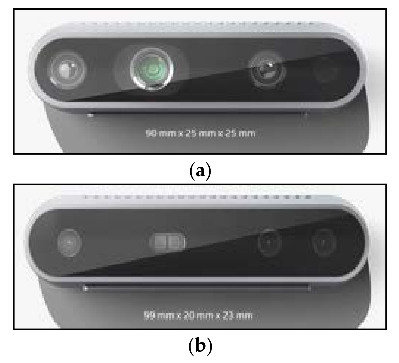
The ZED depth sensor is composed of stereo cameras with a video resolution of 2560 × 1440 pixels (2K) with dual 4 mega-pixel RGB sensors. The two RGB cameras are at a fixed base distance of 12 cm. This base distance allows the ZED camera to generate a depth image up to 20 m (40 m is the maximum distance in the new updated firmware, according to the Stereolabs datasheet) [
16]. The camera contains a USB video device class supported USB 3.0 port backward compatible with the USB 2.0. standard. It should be noted that the ZED 3D depth sensor is optimized for real-time depth calculation using NVidia Compute Unified Device Architecture technology [
16]. Therefore, a corresponding graphical processing unit (GPU) and appropriate computer hardware are required to use it [
16,
17,
18].
The ZED sensor uses wide-angle optical lenses with a FOV of 110°, and it can stream an uncompressed video signal at a rate up to 100 fps in Wide Video Graphics Array (WVGA) format. The depth image is provided with a 32-bit resolution. Hence, the camera gives a very accurate and precise depth image that describes the depth differences, i.e., the different distances from the plane of the camera. Right and left video frames are synchronized and streamed as a single uncompressed video frame in the side-by-side format. Various configurations and capturing parameters of the on-board image signal processor, such as brightness, saturation, resolution, and contrast, can be adjusted through the SDK provided by Stereolabs [
16]. Furthermore, ZED devices support several software packages, called “wrappers,” such as ROS, MATLAB, Python, etc. All these software packages allow the modification of different parameters depending on the user requirements, such as the image quality, depth quality, sensing mode, name of topics, quantity of frames per second, etc. [
16,
17,
18,
19,
20].
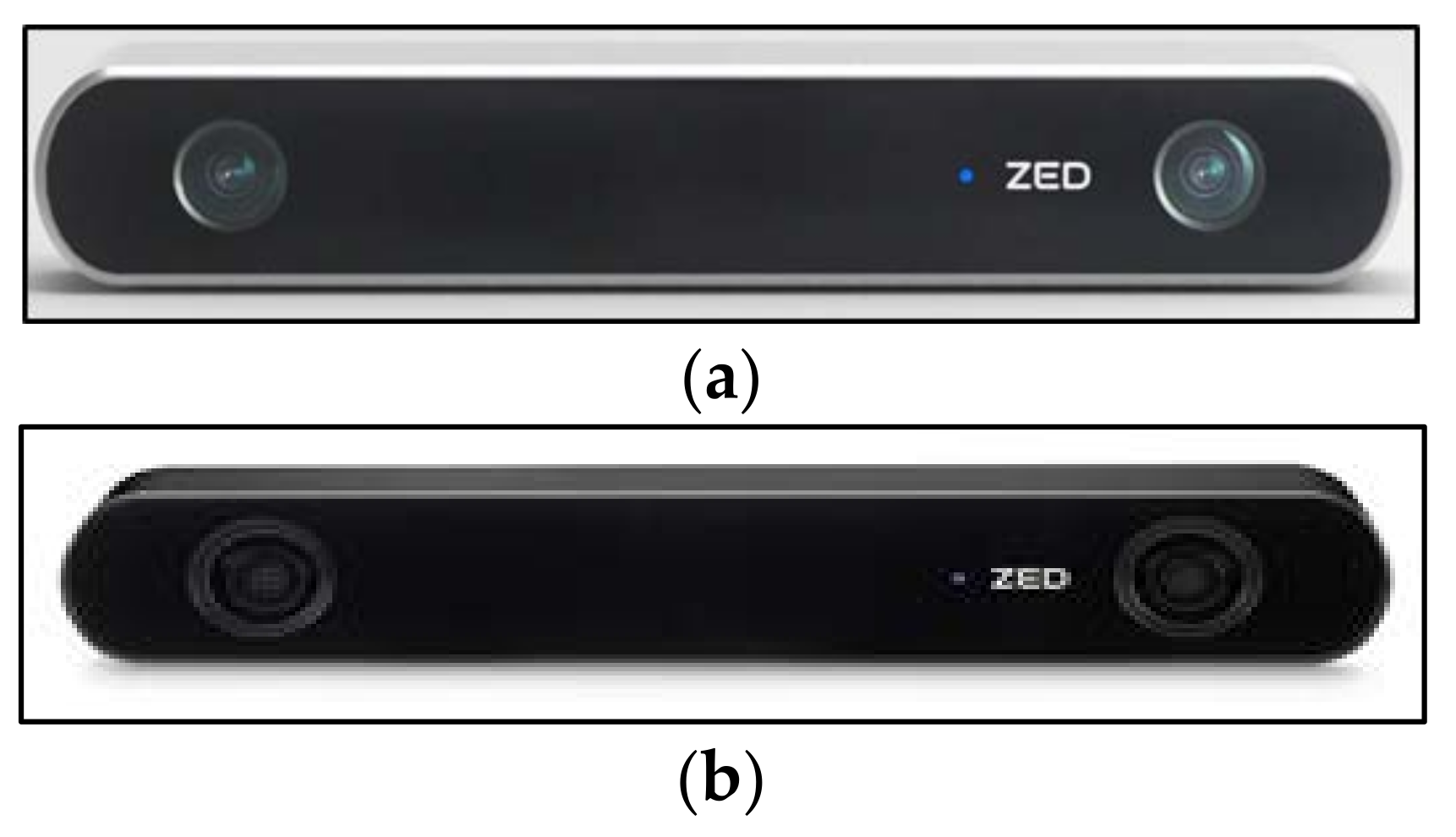
Figure 3 shows the ZED depth sensors [
16].
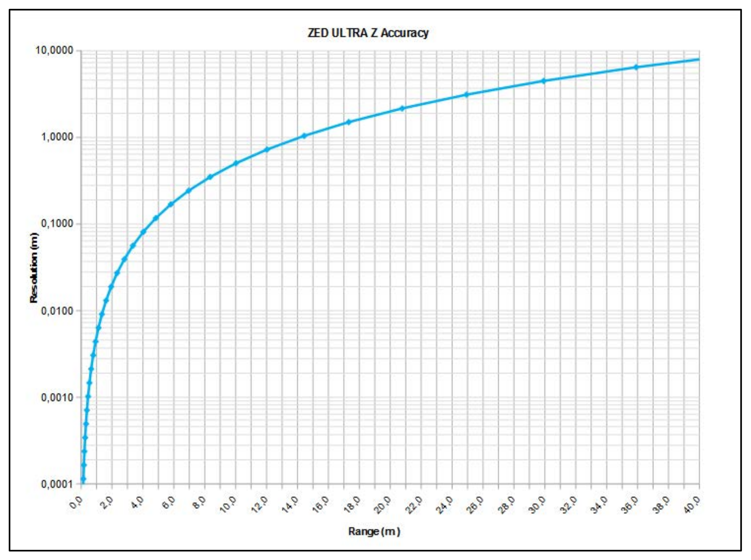
Figure 4 presents the accuracy graph of the ZED depth sensor depending on the distance of an object from the depth camera. As shown, the depth resolution, i.e., the depth precision, is impaired with increasing distance [
16].
Finally, it should be remarked that the ZED depth sensor comes with a unique factory calibration file, which is downloaded automatically. The recommendation is to use the Stereolabs factory settings, but users can also calibrate the ZED sensor with the ZED SDK software package [
16,
17,
18,
19,
20].
The new ZED 2i depth camera has some similarities and shares some properties with the previous version of the ZED depth camera. However, the new ZED 2i sensor includes several significant improvements.
ZED 2i is the first stereo depth camera that uses artificial neural networks (ANNs) to reproduce human vision, bringing stereo perception to a new level [
16]. It contains a neural engine that significantly improves the captured depth image or depth video stream. This ANN is connected to the image DSP, and they contribute jointly to creating the best possible depth map [
16]. Furthermore, the ZED 2i camera has a built-in object detection algorithm [
16]. This algorithm detects objects with spatial context. It combines artificial intelligence with 3D localization to create next-generation spatial awareness [
16]. There is also a built-in skeleton tracking option that uses 18x body key points for the tracking application. The algorithm detects and tracks human body skeletons in real time. The tracking result is displayed via a bounding box, and the algorithm works up to a 10 m range [
16].
Next, this ZED 2i camera has an enhanced positional tracking algorithm that is a significant improvement suitable for robotic applications [
16,
17,
18,
19,
20,
21]. This benefit arises from a wide 120° angle FOV, advanced sensor stack, and thermal calibration for greatly improved positional tracking precision and accuracy [
16]. The ZED 2i depth camera has a built-in inertial measurement unit, barometer, temperature sensor, and magnetometer. All these sensors provide extraordinary opportunities for easy and accurate multi-sensor capturing. These sensors are factory calibrated on nine axes with robotic arms [
16]. The data rates of the position sensors, i.e., the barometer and magnetometer, are 25 Hz/50 Hz. The built-in motion sensors, accelerometer, and gyroscope contribute significantly to the development of robotic applications since there is no need to install any other sensor except the ZED 2i camera itself. The data rate of these sensors is 400 Hz. The thermal sensors monitor the temperature and compensate for the drifts caused by heating. In this way, gathered real-time synchronized inertial, elevation, and magnetic field data along with image and depth are collected. These sensors also contribute to accurate and precise depth sensing. The all-aluminum frame reduces the camera heating that induces changes in focal length and motion sensor biases [
16]. The case in aluminum allows to better dissipate the internal heat generated by the electronic components reducing the internal temperature of the depth camera. Additionally, the case deformations cannot affect the measure of the depth in any way because the lenses do not move. Furthermore, the software is factory calibrated in order to use the temperature information provided by the internal sensors and modify the data accordingly [
16]. All the mentioned motion and positional features indicate that the ZED 2i depth camera is extremely suitable for development of autonomous and industrial robotic applications [
21,
22,
23,
24,
25,
26,
27,
28,
29,
30,
31,
32,
33,
34,
35,
36,
37,
38,
39,
40].
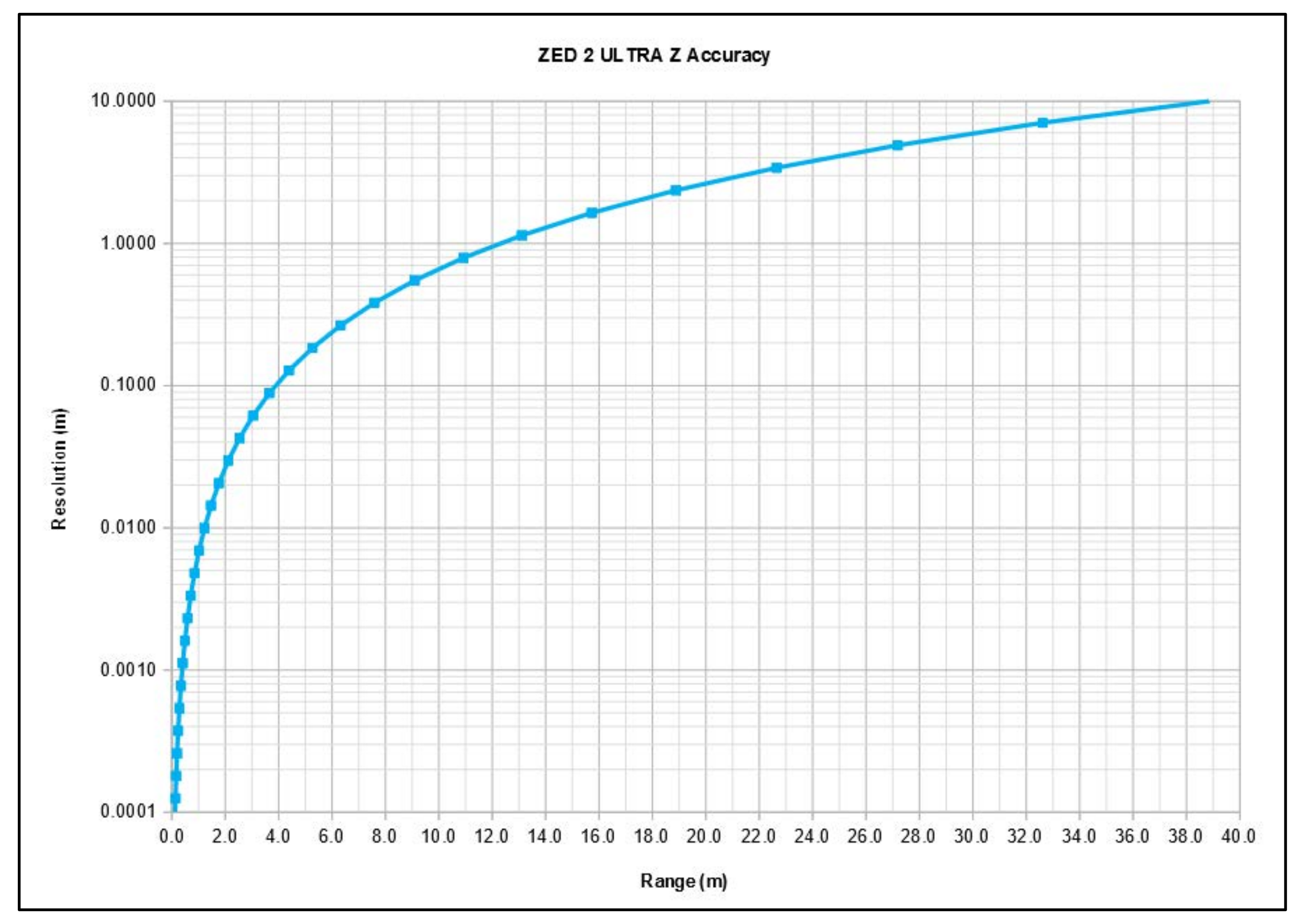
Figure 5 shows the accuracy graph of the ZED 2i depth sensor, depending on the distance of an object from the depth camera. As shown, the depth resolution, i.e., the depth precision, decreases with increasing distance [
16]; however, for instance, at the 1 m range, the accuracy is better than that of the previous ZED, as seen in
Figure 4.
One of the most important improvements in ZED 2i is the inclusion of new ultra-sharp eight-element all-glass lenses able to capture video and depth up to a 120° FOV, with optically corrected distortion and a wider ƒ/1.8 aperture, which allows capturing 40% more light [
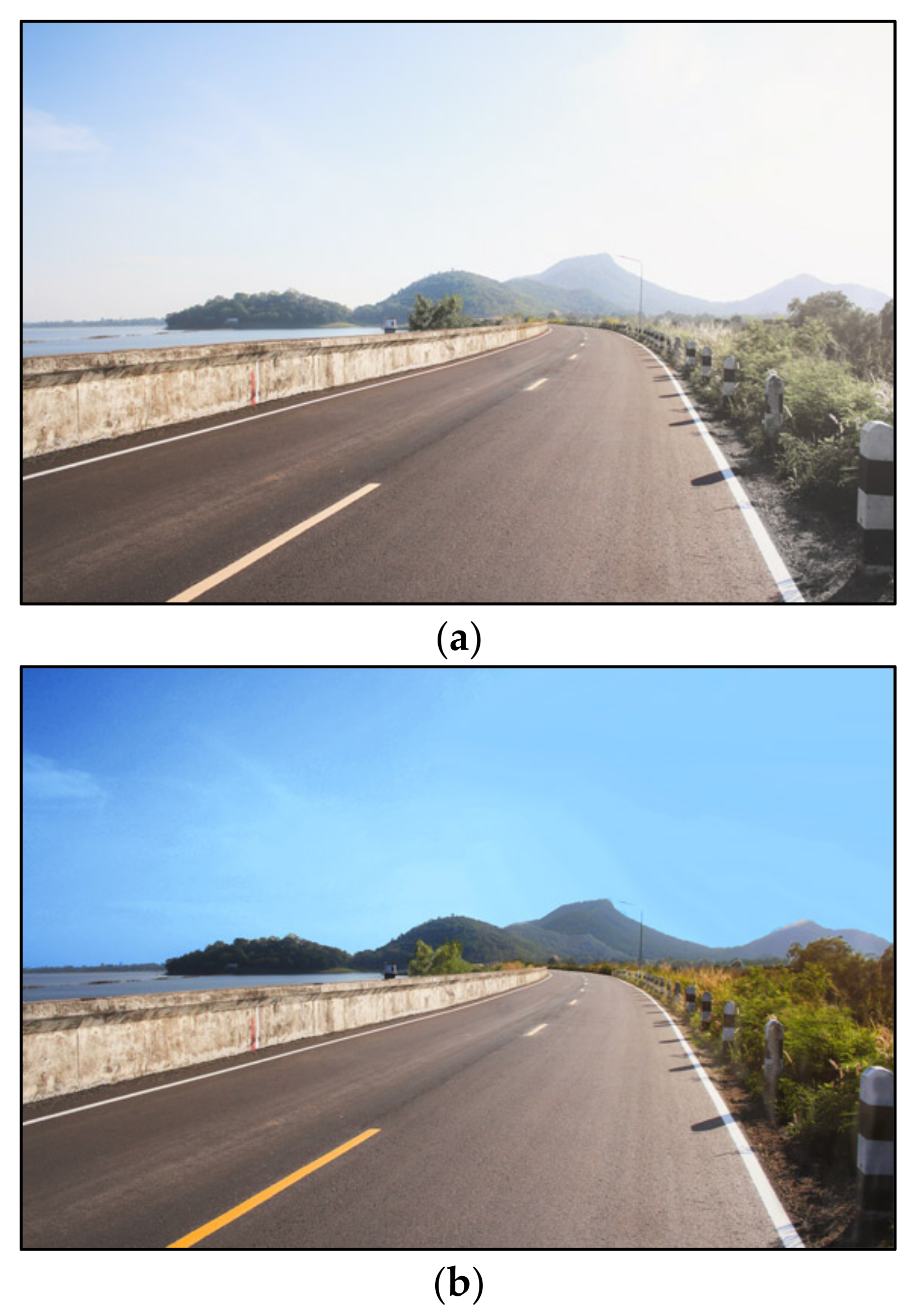
16]. Furthermore, the ZED 2i has an optional feature: the polarizing filter. This built-in polarizing filter gives the highest possible image quality in various outdoors applications. This lens helps to reduce glare and reflections and increases the color depth and quality of the captured images [
16]. The effect of the polarizer can be seen in
Figure 6.
The ZED 2i stereo camera also has two lens options. It is possible to choose between a 2.1 mm lens for a wide FOV or a 4 mm lens for increased depth and image quality at long range, according to the manufacturer [
16]. However, the 4 mm lens option entails delays in delivery [
16]. These are principal features related to all depth cameras since the lenses, aperture, and light significantly affect the image quality of any camera, not only the depth camera. These features enable high-quality depth images to be obtained, upon which promising robotic vision applications can be developed [
41,
42,
43,
44,
45,
46,
47,
48,
49,
50,
51,
52,
53,
54,
55,
56,
57,
58,
59]. According to the Stereolabs [
16], the main features of ZED cameras are listed in
Table 2.
Furthermore, the ZED 2i has an Ingress Protection 66 (IP66)-rated enclosure that is highly resistant to humidity, water, and dust, since the ZED 2i depth sensor is designed for outdoor applications and challenging industrial and agricultural environments, etc. [
16], while the ZED camera, such as the D415 and D435 RealSense cameras, is mainly designed for indoor applications [
7]. Moreover, the ZED 2i has multiple mounting options and a flat bottom, and it can be easily integrated into any system and environment [
16].
Since the ZED 2i can be cloud-connected, there is an option to monitor and control the camera remotely. Using a dedicated cloud platform, capturing and analyzing the 3D data of the depth image is possible from anywhere in the world [
16]. It is also possible to monitor live video streams, remotely control the cameras, deploy applications, and collect data.
Finally, it should be mentioned that there is also a ZED two-depth camera provided by Stereolabs [
16]. The main features and the accuracy graph of the ZED 2i are the same as those of the ZED 2 as the internal sensor stack and the lens configuration of the two sensors are the same [
16]. The only differences are the external enclosure for the ZED 2i, which is IP66 and hence more robust, and the option of a built-in polarizing filter [
16].
The essential features of ZED and ZED 2i depth devices are summarized and compared in
Table 2 [
16].
4. Experiments and Results
In this section, the experiments and their outcomes are explained in detail. Numerous measurements in various situations of different scenes and objects were made with the described four depth cameras, and several results are presented here. The scenes are selected in such a way to present many different situations as possible, with many different objects as possible to cover the aspects of possible obstacle avoidance applications and the aspects of possible applications where high accuracy is needed for object detection. Further, the available depth sensors are using different parameters that are discussed in this paper, and all the parameters of used depth cameras are set automatically by the cameras themselves and its software. In that sense, the goal of experiments is to investigate the resulting depth maps and determine the abilities of the depth sensors in particular capturing situations. The fair comparison of the results will be presented, since the depth maps are very informative as the results of the depth measurements, and they provide the best assessment of the capabilities of available depth cameras themselves, specially from the practical point [
1,
2,
3,
4,
5,
6,
7,
8,
9,
10,
11,
12,
13,
14,
15,
16,
17,
18,
19,
20,
21,
22]. In all the examples, the position and the capturing conditions such as the illumination, angle, shadows, etc., of all the depth sensors were the same for a particular example in order that the results could be compared appropriately. All the depth maps in examples are displayed in grayscale, since with the ZED software only the grayscale depth maps can be displayed [
16]. The RealSense software can display depth maps in various color and grayscale modes [
7], but for a better comparison all the depth maps are presented in grayscale in the paper.
Furthermore, it should be noted that all the examples are provided without any post-processing methods, since the goal was to examine, analyze, and present the capabilities of the depth sensors themselves. All the examples were recorded with the built-in options provided by the depth cameras and their recording software. Both the RealSense and the ZED software support the so-called fill option of the depth map, where the objects in the depth image are smoothed and blurred. This option was suitable for examples where the overall visual experience was preferred, such as panoramas. The opposite of this fill option is the standard high accuracy preset, where the edges of the objects in the depth map are more pronounced in order, such that the finer details in the depth image can be efficiently distinguished. This option is mandatory in applications where high precision and accuracy are the main demands. The effects of these options will be presented later in this section.
It should also be mentioned that the experiments were conducted with two kinds of hardware configurations: with an older, modest quality laptop with an on-board graphic card and a new desktop computer with an NVidia GPU. The goal of using both computers in experiments was to explore the capabilities of the depth sensors depending on the quality of the computer equipment to which the depth cameras were connected. In practice, it can happen that an application does not require state-of-the-art computer equipment or a high-quality depth sensor, so it was convenient to check the capabilities of the depth cameras in this case, as well. The latter case primarily refers to applications that do not require high accuracy and precision of depth measuring of the scene, i.e., applications where the depth map of the environment will be used for orientation and navigation in space when moving the robot or a vehicle. Therefore, the presented examples cover this issue as well.
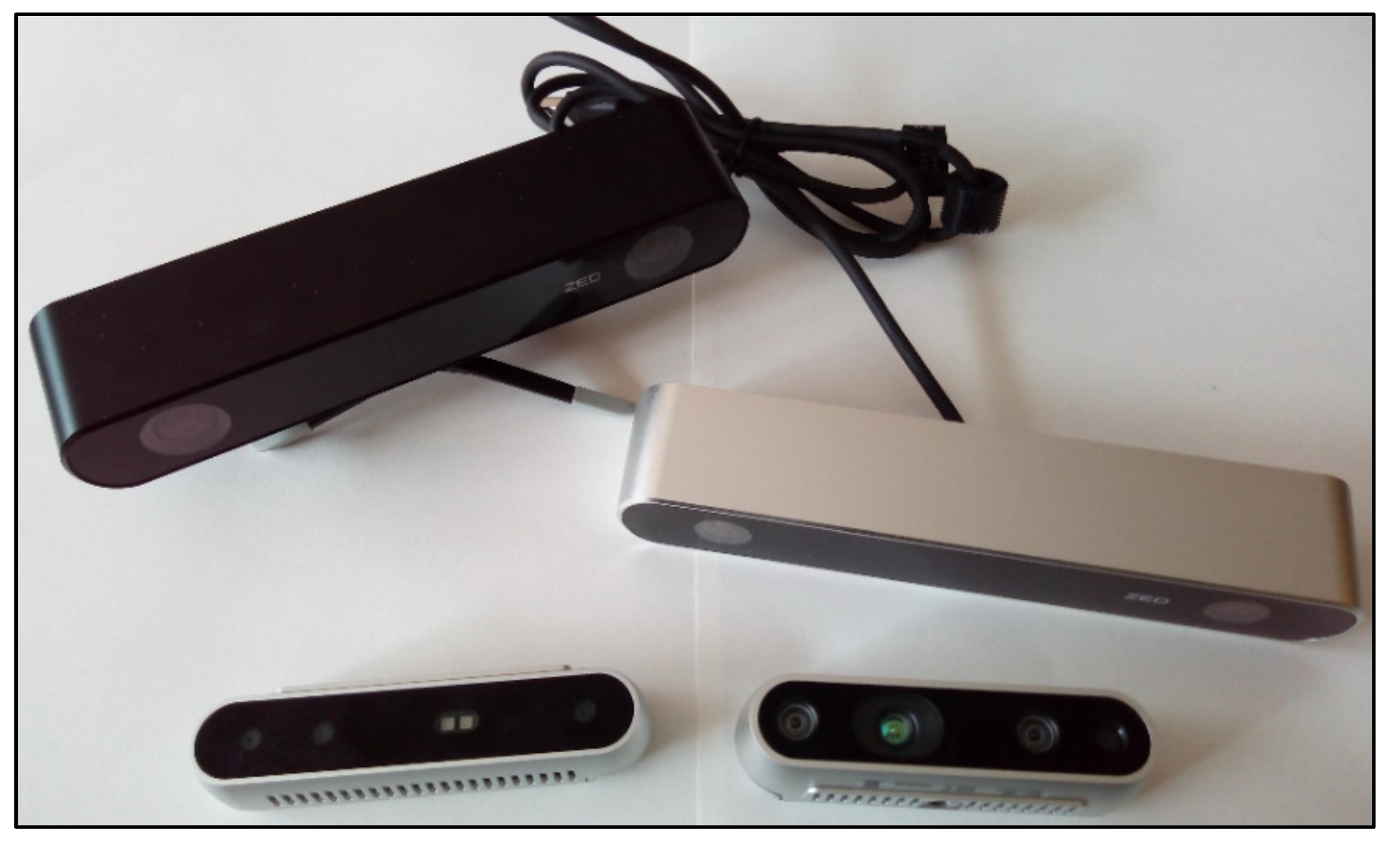
Figure 7 shows the equipment utilized in the experiments.
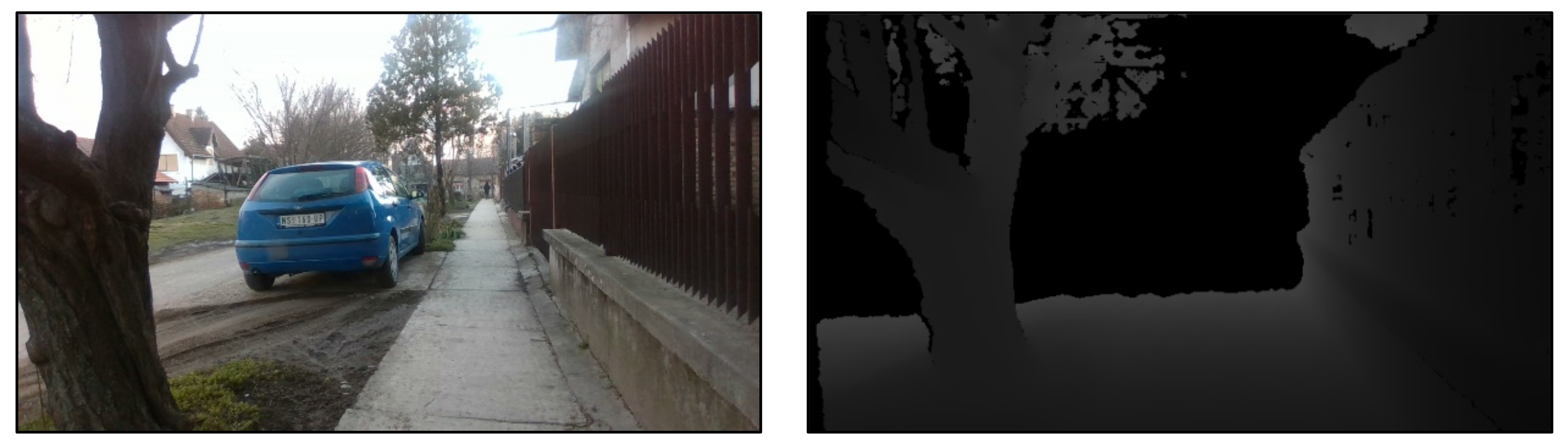
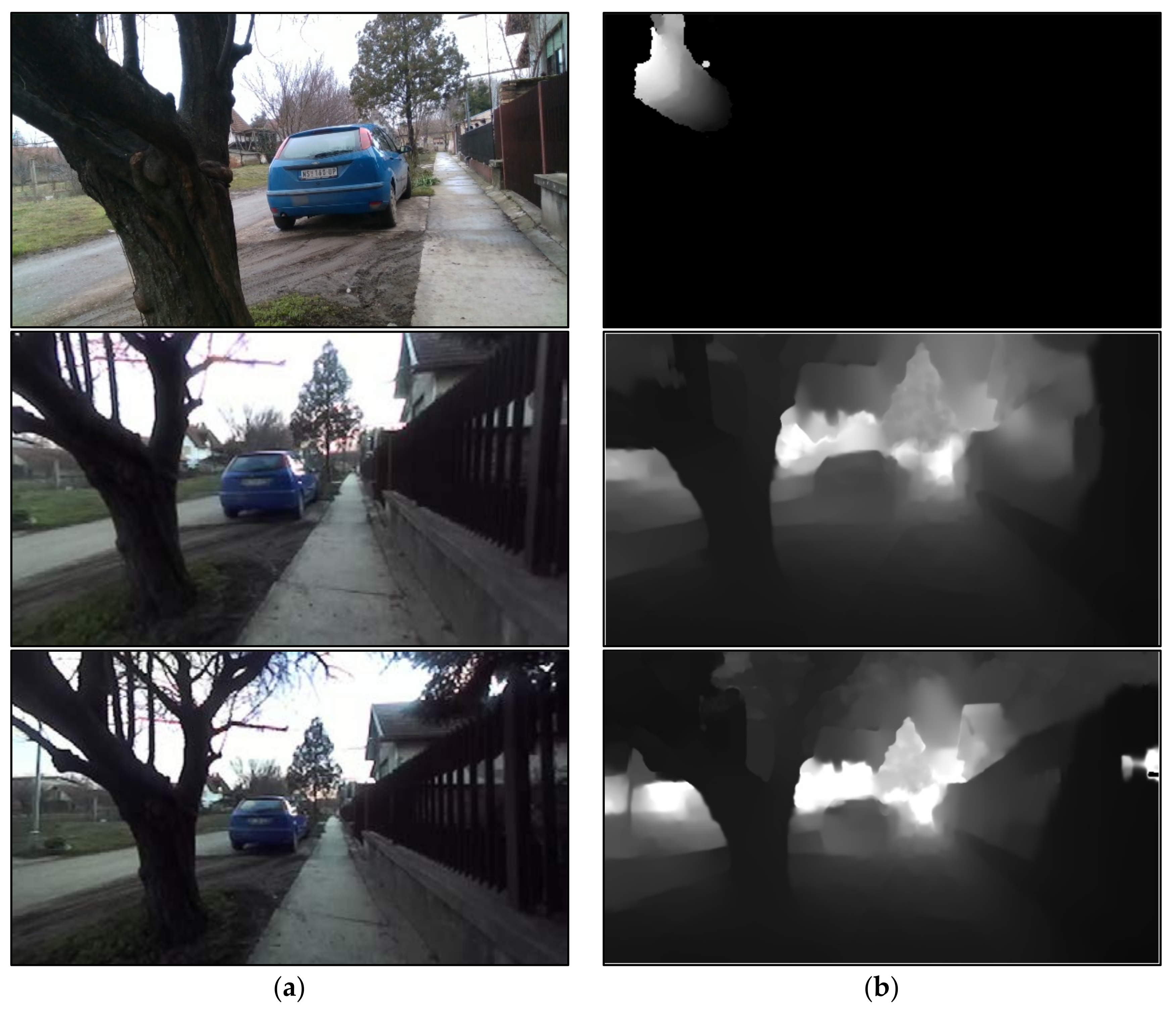
Figure 8 shows color street photos in (a) column and their corresponding depth maps in (b) column, one below another, as recorded with the D435, D415, ZED, and ZED 2i depth cameras, respectively. The first row is the result from the D435 camera, the second row is the result from the D415 camera, the third row is the result from the ZED camera, and the fourth row is the result from the ZED 2i camera. It should be noted that in all further examples the measurement results from the depth sensors are displayed in the same way. Furthermore, the (a) column shows the color images recorded from the left cameras of all the depth sensors, while the (b) column displays the corresponding depth images in all the presented examples in this section. It is important to highlight that the depth images are always aligned with the color images from the left cameras for all the depth sensors, and this is the reason the left camera’s color images are used in all the examples. The color image from the left camera and the depth image share the same set of XYZ coordinates for all depth sensors. It should also be noted that the vertical black, thin areas in the depth images are caused by the distance between the cameras in the depth sensors, and they are called the “dead zones”. In this zone, the depth cameras cannot detect anything in depth [
7,
16]. This is the effect generated by the parallax [
16]. Parallax effect is a difference or displacement in the apparent position of an object viewed along two different lines of sight, and is measured by the angle or semi-angle of inclination among those two lines. Hence, the two-camera sensors, the left and the right sensors, look at the scene from a horizontal distance of few centimeters, so it can happen that part of the scene, objects are not visible by both the sensors [
7,
16]. Accordingly, the first example in
Figure 8 shows the results recorded with the RealSense D435 depth camera. The depth camera was set on the sidewalk, and the illumination was satisfactory, without any sunrays, shadows, and non-specific artifacts. The tree was at a distance of about 3 m from the camera, and the car was about 7 m away from the camera. The fence was 0.5 m away from the depth camera, and it moved farther from the depth camera itself with the growing distance. Other trees, houses, road, etc., can be seen in the photo, but at greater distances. The recording conditions and depth sensor positions were the same for all depth sensors. As noticed in the first example in (a) column, there is a rich content in the captured image. In column (b) the corresponding depth map is shown. The depth map was generated with the so-called default preset in the RealSense Viewer [
7], which provides the filling option for the depth image. As noted, this option ensures an overall visual experience, and the depth image is pleasant to view. The nearest tree, the nearest part of the fence, and the nearest part of the ground are clearly visible, but on the other hand, the car is very dark and invisible in the depth map. This can be considered a good result, since the D435 depth camera and all the other depth cameras are mainly designed for indoor use [
7,
16,
17]. Based on this result, we concluded that the D435 depth sensor yielded a satisfactory depth image of the panorama, and this depth image could be used for applications where the robot orientation and spatial navigation are required. Finally, this measurement result was generated with a modest quality laptop, where the resolution of the color image and the depth map was 1280 × 720 pixels. The same resolution was used in the RealSense D415 depth camera measurement as well as the same default preset.
The second example shows the result of measurement with the D415 depth camera. It can be noticed that the scene is a little narrower because of the built-in optics in the depth sensor; hence, the recorded color image in the first column contains fewer details. Unfortunately, the depth map is almost invisible, and only a small part of the scene is present near the tree area. The reason for this lies in the architecture and properties of the D415 camera itself, since the D415 depth sensor is intended for high accuracy measurement of small indoor distances [
7]. Therefore, the obtained results were not a surprise, and any useful visible result in the depth image would have been a gain in this case.
The third example in
Figure 8 was recorded with the ZED depth sensor. The color image on the left contains much more detail. The reason for this wide view was the wide FOV of both ZED depth sensors. Moreover, since the modest quality laptop without the GPU was used for the recording, the maximal supported resolution was only 672 × 376 pixels. Despite the poor resolution, the recorded scene is of good quality. The recording was done with the ZED Explorer [
16], and the images were saved in *.svo [
16] files. Later, using the desktop computer and the NVidia GPU, the depth maps were generated via the ZED Depth Viewer Tool [
16]. The reason for this was the absence of a high-quality GPU on the laptop as required by the ZED depth cameras for depth calculation [
16,
17]. Unfortunately, the original resolution of the saved images could not be changed during the depth determination; hence, the depth measurement was done with a resolution of 672 × 376 pixels. The corresponding depth map is shown on the right.
Regardless of the stated quality losses, the generated depth image is of very good quality and could be very useful in applications where the robot needs to orient itself in space. In the obtained depth map, not only the tree and the fence are correctly visible, but the car is visible, too, along with the far trees and the houses. Therefore, we concluded that the ZED depth sensor can generate a satisfactory depth map, even with the degraded performance. During the depth calculation, the so-called ultra-quality depth determination [
16] was used with the filling option in order to generate a pleasing depth image for an overall visual experience.
Finally, the fourth example shows the result generated with the ZED 2i depth sensor. All the settings in the ZED software [
16] were the same for the ZED 2i camera as for the ZED camera. Since the ZED 2i has wider optics and FOV, the color image is the most detailed of all the examples in
Figure 8. This is to be expected regarding the features of all the depth sensors in this research. The determined depth image is displayed in the right column and as can be noticed, it contains more details because of the wider angle of view. Additionally, the quality of the depth map is almost the same as that of the ZED camera, and possibly the details are a little sharper. Hence, this depth camera can be very useful in applications where the robot’s spatial orientation is mandatory.
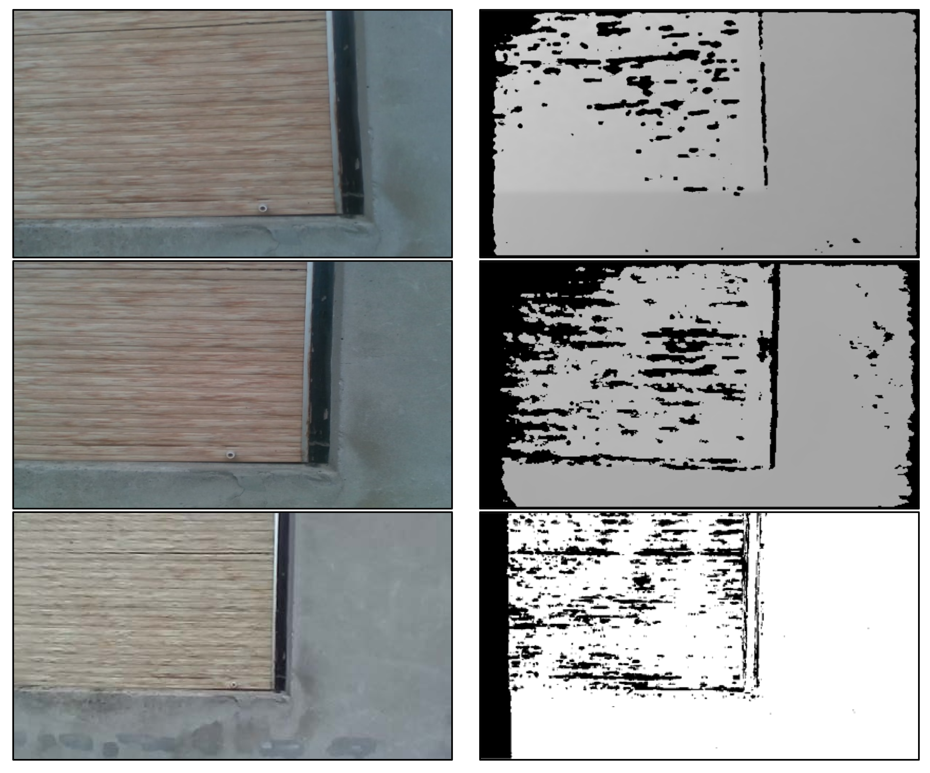
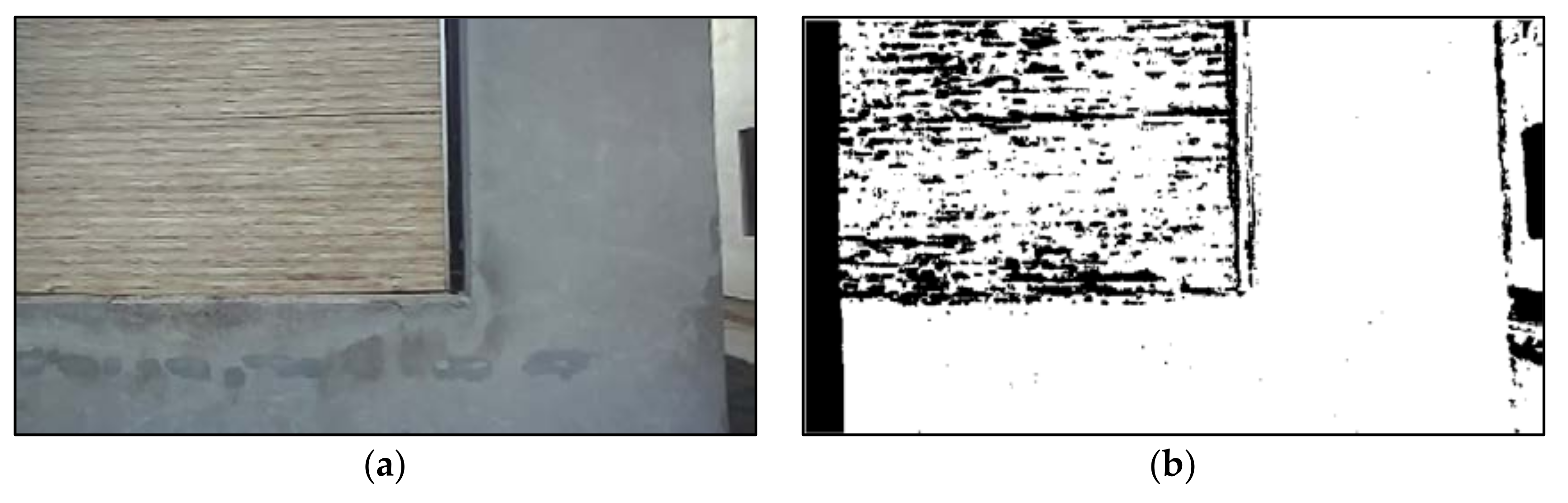
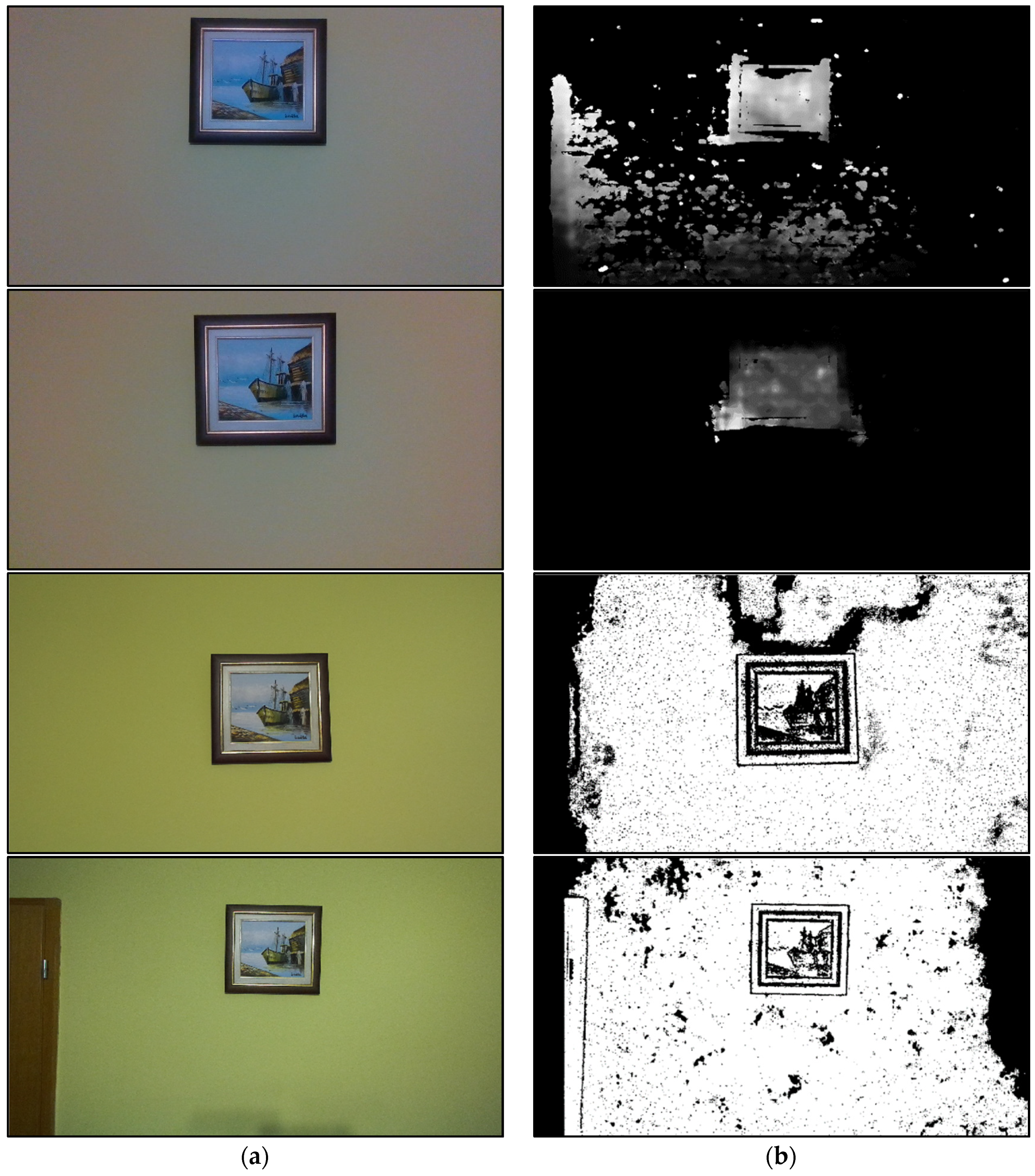
Figure 9 presents the example of window frame depth measurement on a facade. This experiment reflected the necessity of accurately determining the depth for industrial robotic applications, such as painting robots [
17,
20]. The goal in this and similar applications was to separate the background from useful objects or surfaces. In order to achieve this, it was very important to clearly distinguish the edges of objects in depth in the depth images. The depth sensors in all measurements were set 1 m away from the wall. The depth difference between the wall and window was about 8 cm.
In the first two examples in
Figure 9 the resolution of the D435 and D415 sensors was 1280 × 720 pixels, and this resolution was used in all the examples in this paper. However, since the accuracy and precision were very important, the high accuracy preset [
7] was used in these measurements, since the goal was to distinguish the wall from the window. As we see in first two color images, they are almost of the same quality, without any significant differences. However, the depth maps are very different. It can be seen that in the first example, the depth map recorded with the D435, the window edges are not clearly visible, especially the bottom region. This result will also affect the post-processing, since it would be very difficult to distinguish the window frame in order to separate it from the wall. On the other hand, the second depth image in
Figure 9 shows the result generated by the D415 depth camera, where the window frame is clearly visible and distinguishable. Later, this result can be post-processed successfully to separate the wall from the window. However, observing the depth images of the D435 and D415 cameras, one can notice the noise and very poor shade distinction of the surfaces of the wall and the window. The reason for this was the poorer ability of the sensors themselves that are built into RealSense cameras, compared to those in the ZED cameras.
The third and fourth image examples show the results obtained by the ZED and ZED 2i depth cameras. In both examples where the ZED depth sensors were utilized, the image resolution was 672 × 376 pixels, the depth calculation setup was in ultra-quality, but now with the standard preset [
16] recommended for high depth accuracy measurements. The wider FOV in both color image samples should first be noticed. Because of the wide FOV in the fourth image obtained from the ZED 2i, part of adjacent building can also be seen in the right side of the image. Therefore, the ZED 2i would be very useful for facade painting application via robots because from one position it can capture a very large wall surface in the image vision stage. Furthermore, in both depth maps the window frame is clearly separated. These results are very suitable for additional image processing in order to extract the wall area intended for painting [
20]. However, we noticed that the measured window edges are more preserved in the fourth example, namely, in the depth map measured by the ZED 2i. The reason for this was probably the better lens optics of the ZED 2i camera compared to the previous version, the ZED camera. In the depth map generated with the ZED 2i, the edge of the building is visibly preserved relative to the background. In this example, it was expected that the window should have a well-defined distance determined by depth cameras, and gray level different with respect to the wall. On the contrast, the window area presents many horizontal dark lines and its gray level is the same as of the wall. According to depth camera manufacturers, the texture of the window is not very informative, and the wall texture too, and this problem results the depth maps seen in
Figure 9b [
16]. Additionally, the window presents many black pixels that correspond to zones with no depth information from the same reason. The final conclusion based on the examples in
Figure 9 was that the ZED depth cameras yielded much better accuracy and depth maps than the RealSense depth cameras in measurements where accuracy are mandatory. Based on the images in
Figure 9 the difference in the quality of the equipment capabilities is obvious for possible painting robot application.
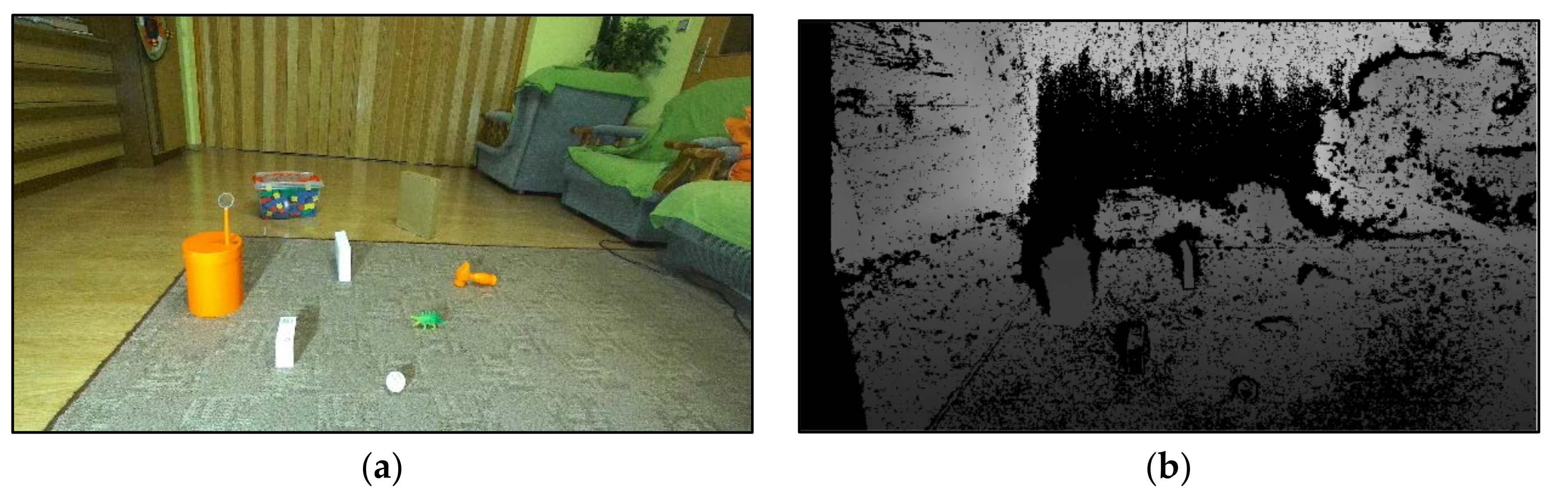
The experiment presented in
Figure 10 depicts a homemade polygon for robotic application where the main goal is obstacle avoidance. Objects of various dimensions and shapes were randomly arranged in the room at different distances from the depth camera position. The lighting of the room came from a common chandelier with five LED bulbs with so-called natural yellow light. Some of the objects were very small, such as a table tennis ball, a small dinosaur figure, and a magnifying glass placed on a big orange box. The dimensions of the toy hammer, the white boxes, the brown box, and the box with wooden block were bigger. This polygon could serve as a movement testing polygon for a small robot. Naturally, this setup could be expanded with more objects at greater distances from each other in a room of much larger dimensions for larger robots. From the color images, it is obvious that a depth map with great accuracy was needed, since there were small objects in the scene that needed to be avoided. The closest object was about 1 m away from the camera, and the farthest object about 3 m away. Hence, the previously mentioned presets for high accuracy depth measurements were chosen in all depth sensors [
7,
16].
The first example in
Figure 10 shows the images captured with the D435 depth camera. The resolution of the depth sensor was 1280 × 720 pixels, as was the resolution of the D415 depth camera in the second example in this figure. As can be seen, the color image is a little blurred because of the illumination, but the image can be considered as satisfactory. The corresponding depth image is shown in the right-hand column. The depth sensor detected the object very superficially, especially the objects with small dimensions. This was an expected result, since the D435 depth camera is not designed for applications where high accuracy is mandatory. However, the objects are detectable in the depth map, and the depth map could be used for an obstacle avoidance application.
The second result presents the measurement obtained with the D415 depth sensor. The quality of the color image is similar, possibly less blurred compared to the color image captured with the D435 camera. Still, the corresponding depth map in the right-hand column is much better, and the objects are more visible in the depth image. The drawback is that the farthest objects were not detected with the D415 sensor. This was because the D415 sensor cannot detect far objects, as was shown in previous examples. However, this problem would not affect the possible robot movement application, since the robot would receive the depth maps correctly, only from shorter distances, and it would process them.
The third and fourth examples show the results captured with ZED and ZED 2i depth sensors. The main difference compared to previous examples is the resolution. In this and in next examples, the resolution of the ZED cameras was 2208 × 1242 pixels for both the color and depth images. The depth calculation mode remained the standard ultra-quality [
16]. Again, because of the large FOV, the images contain more details, especially the image captured with the ZED 2i in the fourth row in
Figure 10. The recorded color images are high quality, and they are very sharp. In the third example obtained from the ZED depth camera, all the objects in the depth map are visible and detectable; however, the image is not very pleasing to view because of the many details in it. The depth image is considered accurate and precise; hence, it could be used for robot movement applications.
In
Figure 10, the fourth example in the second column shows the depth image obtained with the ZED 2i. The yielded depth map contains all the important objects and the large background from the color image. Since the ZED 2i FOV is very large, the depth image has many details, and some of them are not significant for the possible robot movement application. This is considered to be a disadvantage in some situations. However, the preferred objects are accurately recognizable in the depth map. Based on the examples presented in
Figure 10, all the depth sensors could be used in robot movement applications for obstacle avoidance where the objects are not very small, since all the sensors yielded satisfactory depth maps. If the objects intended for avoidance are of very small dimensions, the ZED sensors could be the solution, since these sensors can measure and detect small depth differences in practice.
The next three examples were experiments where high measurement accuracy and precision were required. Medical and industrial robotic applications require very accurate and precise depth maps, and the goal of the following experiments was to investigate the capabilities of depth sensors in such examples and setups. In the examples in
Figure 11,
Figure 12 and
Figure 13 the high accuracy presets were used with resolutions of 1280 × 720 pixels for RealSense depth cameras and 2208 × 1242 pixels for ZED depth cameras. The RealSense Viewer tool or the RealSense cameras sometimes crashed when the resolution was set to a maximal 1920 × 1080 pixels, and this is the reason why these results were excluded from this paper.
In
Figure 11 the depth measurement of a painting is presented, where the painting was the object intended for detection via depth map. The painting frame was about 2 cm thin against the wall area, and the wall was similarly yellow-colored. The height and width of the painting were not significant since the depth camera calculates the depth information in order to generate the depth map. The depth sensors were about 1.2 m away from the wall in all measurements. The lighting of the room was derived from the same common chandelier with five LED bulbs.
The first example shows the results yielded with the D435 depth camera. The yellow color of the wall is not overly pronounced, since the image sensors of the camera cannot sense a better color image. Still, the color image is good enough, and all the details are recognizable. The corresponding depth image in the right-hand column is considered as good, since the painting frame is visible, but the painting area is damaged a little and not clearly visible. This shortcoming could cause problems for post-processing algorithms when the goal is the detection and extraction of the painting. There are also some noise and artifacts remaining in the background on the left side and under the painting in the depth map. Hopefully, these artifacts will not affect the detection algorithm for the desired object from the depth image.
The second experiment presents the images obtained from the D415 depth sensor. In this example, the color image is much better, since the yellow color of the wall is more pronounced, and the painting details are more visible. Furthermore, the corresponding depth image in the (b) column is more accurate and precise, and the painting frame is detected very well, without the surrounding artifacts and noise. This result was expected, since the D415 depth camera is designed for applications where high accuracy is the main demand, compared to the D435 depth camera where the visual experience is the goal [
7]. This depth map is considered as very good, and it could be very usable in robotic vision applications.
The third example shows the measurements obtained with the ZED depth camera. The color image is high quality, and the yellow color of the wall as well as all the details in the image are clearly visible. The corresponding depth map is shown next to the color image, and it is very accurate. All the details in the painting as well as the painting frame itself are clearly visible. However, most of the wall area is visible, too, but this can most likely be eliminated with post-processing algorithms.
The fourth example in
Figure 11 presents the results obtained with the ZED 2i depth sensor. The effect of a wide lens is noticeable, since a larger wall surface was covered with this camera. Again, the colors and details in the depth image are clearly visible, even the door on the left is in the scene. The measured depth map is very accurate. All the details in the painting and its frame are clearly visible, even the edges of the door. Again, part of the background wall area is also visible in the depth map, but it and the door area can be eliminated later with post-processing if needed. Furthermore, it can be noticed the drawing inside the picture in depth maps obtained with ZED cameras. The reason of such results could be because the sides of the picture present minimal occlusions that cannot be matched during the stereo matching step of the stereo algorithm. The black borders are zone where the depth information is not available [
16]. Additionally, the boat probably has a homogeneous color that does not generate depth results. The boat on the depth map is indeed black, which means that no depth is detected in that area hence the depth map contains some part of the drawing inside the picture area in black color that acts as a texture [
16]. However, the edges of the picture area are clearly and accurately distinguishable in-depth maps measured with ZED sensors, and this information would be used in post-processing.
Based on experiments presented in
Figure 11, we concluded that the ZED and ZED 2i depth sensors yielded accurate and precise depth maps, but in certain robotic applications, the depth maps generated with the D435 and D415 depth sensors could be better used for robotic vision purposes, since the picture area is separated from the background. The reason of better depth maps lies in the fact that the RealSense cameras use IR sensors for depth measurement [
7], and this is the key reason of the acceptable picture area in depth maps generated by RealSense cameras. However, in the absence of satisfactory computer hardware, the measurements need to be limited on RealSense depth cameras or equipment with similar requirements, since these cameras do not require high quality GPUs for depth calculation.
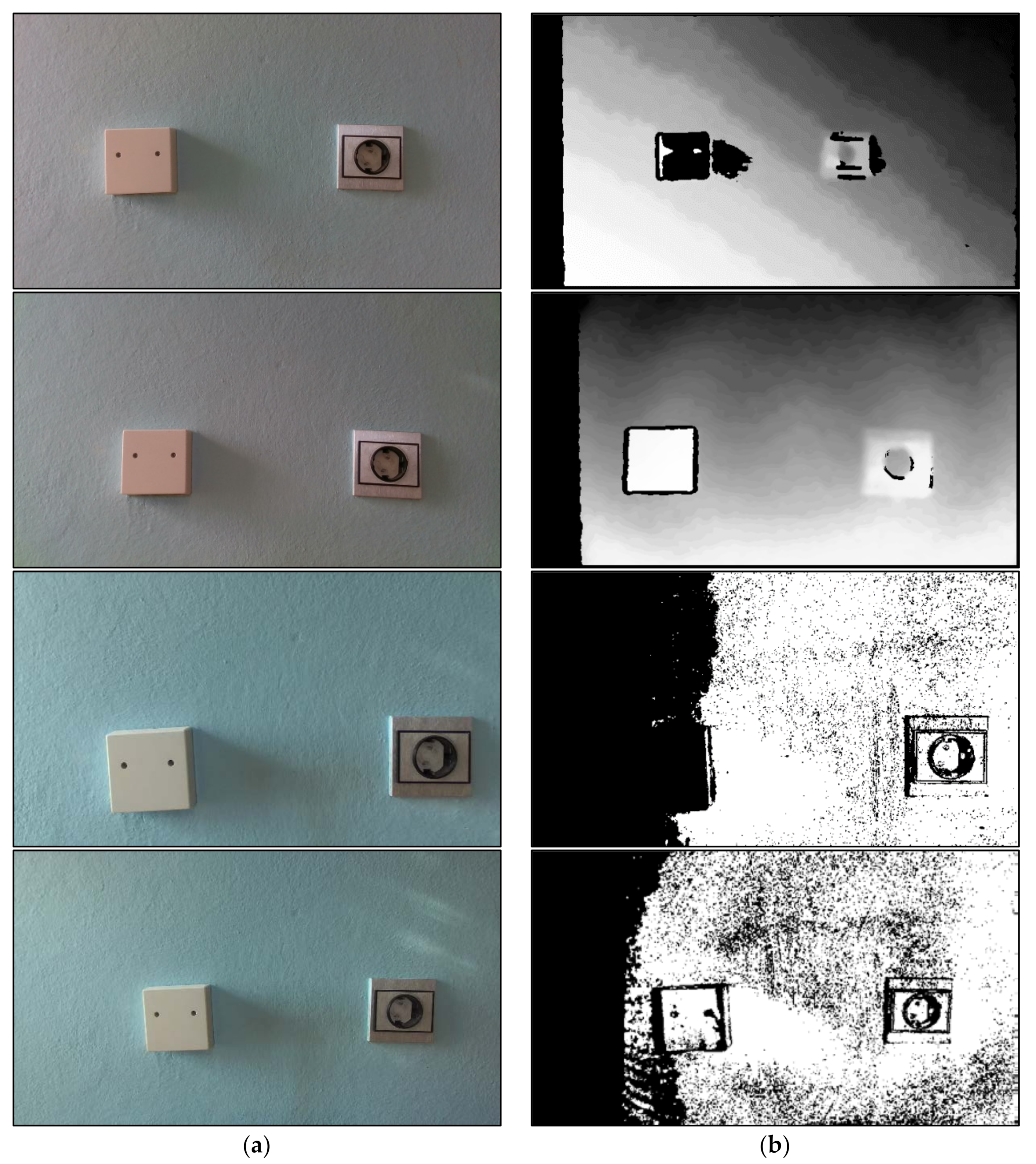
In
Figure 12 an experiment is presented where the goal was to detect the AC socket in the wall. Near the AC socket there was also a junction box. The AC socket was about 7 mm thin, and the junction box, about 2.2 cm thin. The measurements were conducted in daylight, and the windows were to the left of the scene, as was the illumination. The area around the junction box was brighter, since it was closer to the window compared to the AC socket, and it obtained more light. The depth camera distance from the wall was set to the minimum depth limits. The minimum depth limit of RealSense cameras is around 30 cm, and the minimum depth limit of ZED cameras is around 20 cm; hence, these were the distance positions from the wall in these experiments.
In the first example in
Figure 12, the D435 depth camera captured a very good color image, as can be seen on the left. However, again the wall color is not pronounced, since the blue color is very poor in the image. In the right-hand column, the depth map is shown. The depth image is not very clear, the AC socket is very hazy, and the junction box is not visible. Hence, this depth map cannot be used for robotic vision applications. This result was not unexpected, since the D435 is not very accurate and not suitable for applications that demand high accuracy and precision [
7].
In the second example, the quality of the color image recorded with the D415 is similar, but the corresponding depth map is significantly better. The frame and edges of the junction box are clearly visible, and the desired AC socket is easily distinguishable. However, the upper part of the AC socket is blurred and hazy. This result can be considered satisfactory for robotic vision applications, since it provides enough information for further image processing. This was also an expected result, since the D415 camera is designed mainly for applications with high accuracy requirements at small distances [
7].
In first two examples in
Figure 12b, the wall area is at the same distance from the depth camera plain, however the first two depth maps show different gray levels inside the wall area. The reason for this phenomenon lies in the next explanation [
7,
16]. The gray levels depend on the range of the scale used to render the depth map. If the range is short, the “minimum” depth difference can be visible in object at similar distances. On other hand, if the range of the scale is too large, some objects may not be visible in the image. Additionally, the capturing conditions (illumination, shadows, darkness, etc.) can affect to the visualization of depth maps too. Furthermore, when measuring large areas, such as walls whose planes are at a certain distance from the plane of the depth camera, the results may be scattered, dispersed and different gray levels can occur since, in real-life scenarios, the distances between the wall and depth camera are different in relation to the direct distance of the depth camera from the wall surface itself. Such phenomena are possible due to the imperfections of the depth sensors themselves, and due to the illumination and shadows, and can affect the depth calculation results of the stereo algorithm [
16]. Hence, only through experiments the best possible depth map can be achieved [
7,
16]. There are no universal solutions, and the appropriate measuring conditions must be determined for each application and scene separately [
7,
16].
The third example shows the images obtained from the ZED depth camera. The color image on the left can be considered as perfect. The generated depth map in the right is very accurate; the AC socket is clearly visible, including the child protection holes (the round white area in the middle of the AC socket). This result was very good, despite the junction box not being visible (which was not the goal of this experiment). The reason why the junction box is not visible lies in the illumination from the left. The junction box got more light, this light blinded the camera sensors, and the objects illuminated from the left, i.e., the junction box, are not visible in the depth map [
16]. This is a common problem with passive stereo cameras because the illumination can cause false detection [
16].
The final example in
Figure 12 shows the results obtained with the ZED 2i depth camera. The color image is very good, and all the details are clear. There are some light reflections above the AC socket, which can cause some negative effects in the calculated depth map. The depth image is displayed on the right. The obtained depth image is noticeably very precise and accurate, and the AC socket and junction box are emphasized well. Quite likely, the polarizing filter eliminated some illumination and light reflection, and the result is the good depth image. Even the small holes in the box and socket are precisely visible in the depth image.
According to images in
Figure 12, the ZED 2i depth camera generated the best depth image of all available depth cameras. The reason for this is primarily its improved optics, which include a polarizing filter [
16].
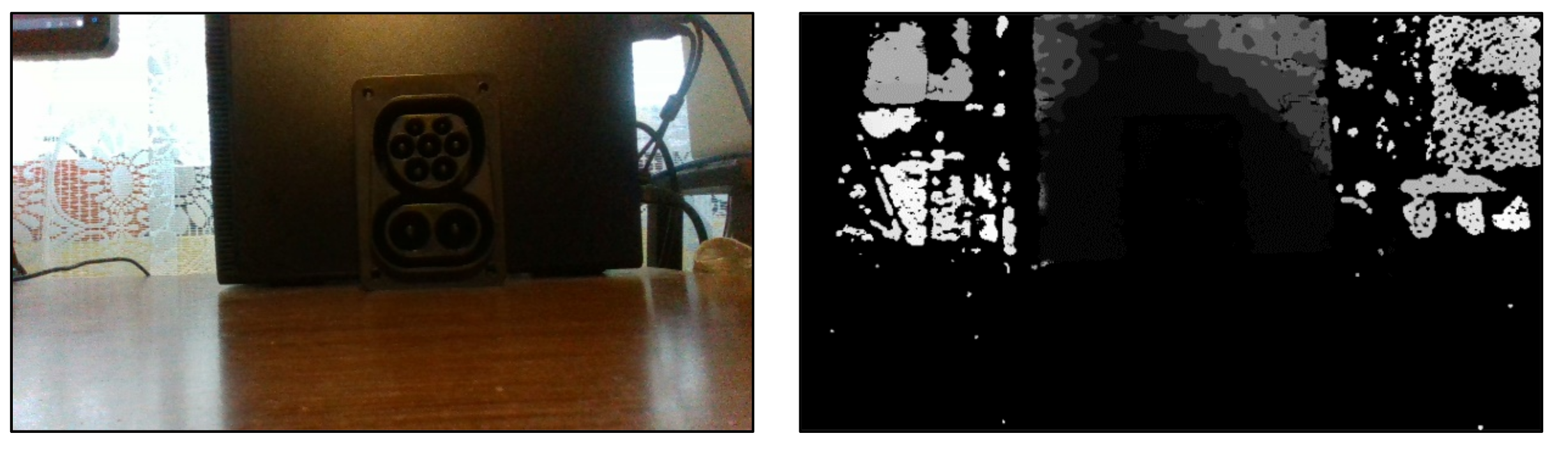
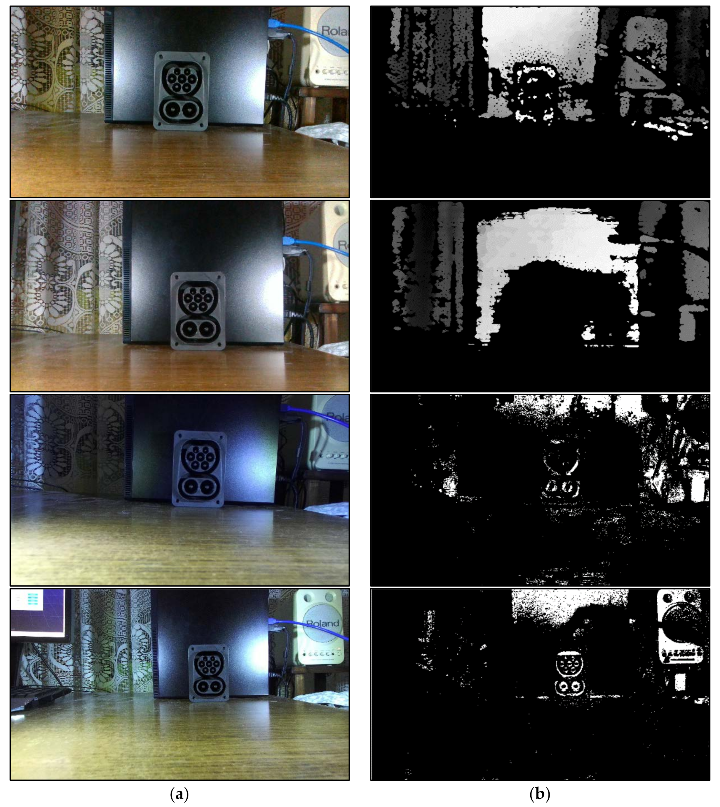
The next example in
Figure 13 shows the results obtained in measurements where high precision and accuracy were mandatory.
Figure 13 shows a special electric car charging socket, the so-called CCS2 socket. This example is very interesting, since the socket was pure black and very dark. The textures of the socket were not clearly visible. The holes around the electric contacts as well the electric contacts themselves were very dark. The background of the socket was also black. The goal of this experiment was to find and analyze the limit case of measurement, when the details of the object itself are very poorly visible and very dark. Dark objects reflect light less, which results in poorer capabilities of all depth cameras since the textures of dark objects are not visible appropriately, and makes it very difficult to calculate the depth of scenes which contain dark objects and materials [
7,
16]. The lighting of the room was derived from the same common chandelier with five LED bulbs in this example, and the background light was partly derived from sunrays through the window located behind the black background and socket. The depth sensors were set about 30 cm away from the CCS2 socket in all measurements. It should also be noticed that the sunrays from through the window radiated directly at the depth camera, and there were shadows in the image. The goal of such experiment was to analyze the behavior of depth sensors in real applications with various illumination sources acting simultaneously.
In
Figure 13 the first example shows the result of recording with the D435 depth sensor. The color image on the left is a little blurry, but the details are clear. The corresponding depth map is displayed on the right. We see that the CCS2 socket is invisible, and the depth map contains lot of noise and artifacts.
The second example shows the result of capturing with the D415 depth camera. The color image on the left is similar, and the depth map on the right is almost pure black, without any useful content. These results were expected since the RealSense cameras cannot handle the light reflection and the direct illumination [
7].
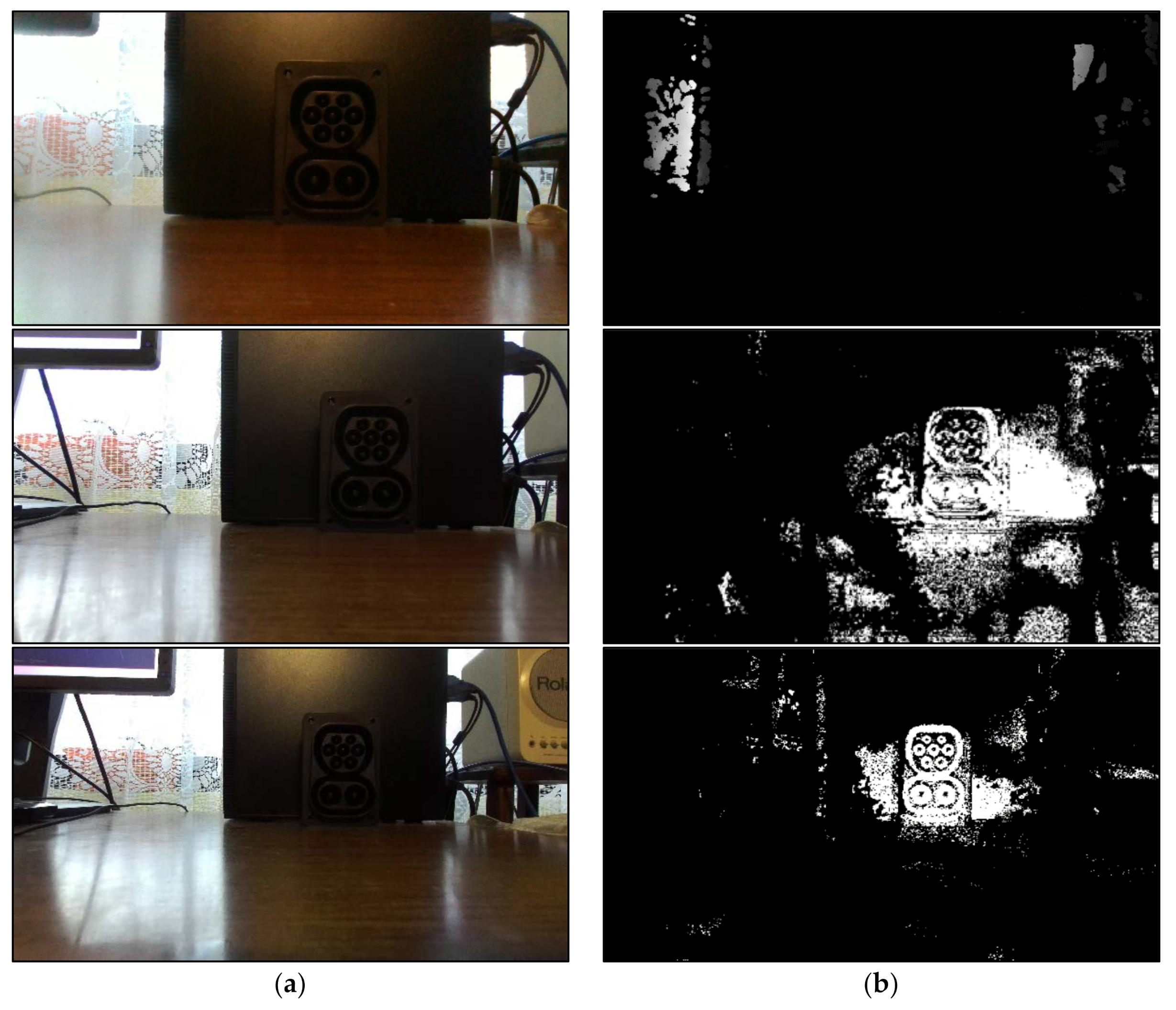
The third example presents the measurements obtained with the ZED depth camera. The color image on the left is very good, and it contains more details owing to the wider FOV and better lens. The yielded depth image is displayed in the right-hand column. The socket is visible in the depth map; however, its region is very noisy and fuzzy, and it cannot be clearly separated from the background. Obviously, the dark surface of the CCS2 socket and the direct illumination affected the image sensors, making it difficult to detect the desired area in the image. Still, this is a much better result compared to the results generated with the RealSense depth sensors.
The final measurement in
Figure 13 presents the result obtained with the ZED 2i depth sensor. Again, the wider FOV provided more details in the color image, and the polarizer lens handled the illumination and reflection to a certain extent. The obtained depth map is displayed on the right. The measurement result is significantly better compared to the depth map generated with the ZED. The CCS2 socket is clearly visible, with less noise and artifacts. The electric contact and the holes are also clearly visible; hence, this depth map could be used for robotic vision application. Apparently, the high-quality lens and polarizing filter provide more features in the ZED 2i than the depth cameras with modest quality lenses.
As it can be noticed in
Figure 13, a not good illumination reduces the quality of the visual features degrading the performances of the stereo matching algorithm in ZED cameras. Dark objects and materials do not reflect the light (they are absorbing the light) and so there is no appropriate visual information to process. Since ZED cameras has no active illumination, so the darker is the scene, and less visual information is available. If the light is indeed too strong the effect is dual, but the result is mostly the same, the depth map will be poor [
16]. The same problem is with the IR laser in RealSense cameras, since dark objects and materials does not reflect the light suitably, there is no suitable visual information to process even with the laser [
7]. Sometimes a good lighting system can help with stereo vision, but the dark object must be illuminated using different angles to create shadows that act as visual textures. Unfortunately, this is very hard to achieve and there is no reliable and unique solution [
7,
16].
Based on the examples in
Figure 13, the ZED 2i depth sensor yielded the most accurate depth map in applications where the objects were not clearly visible because of the dark colors and invisible textures, and in the presence of dim illumination and shadows.
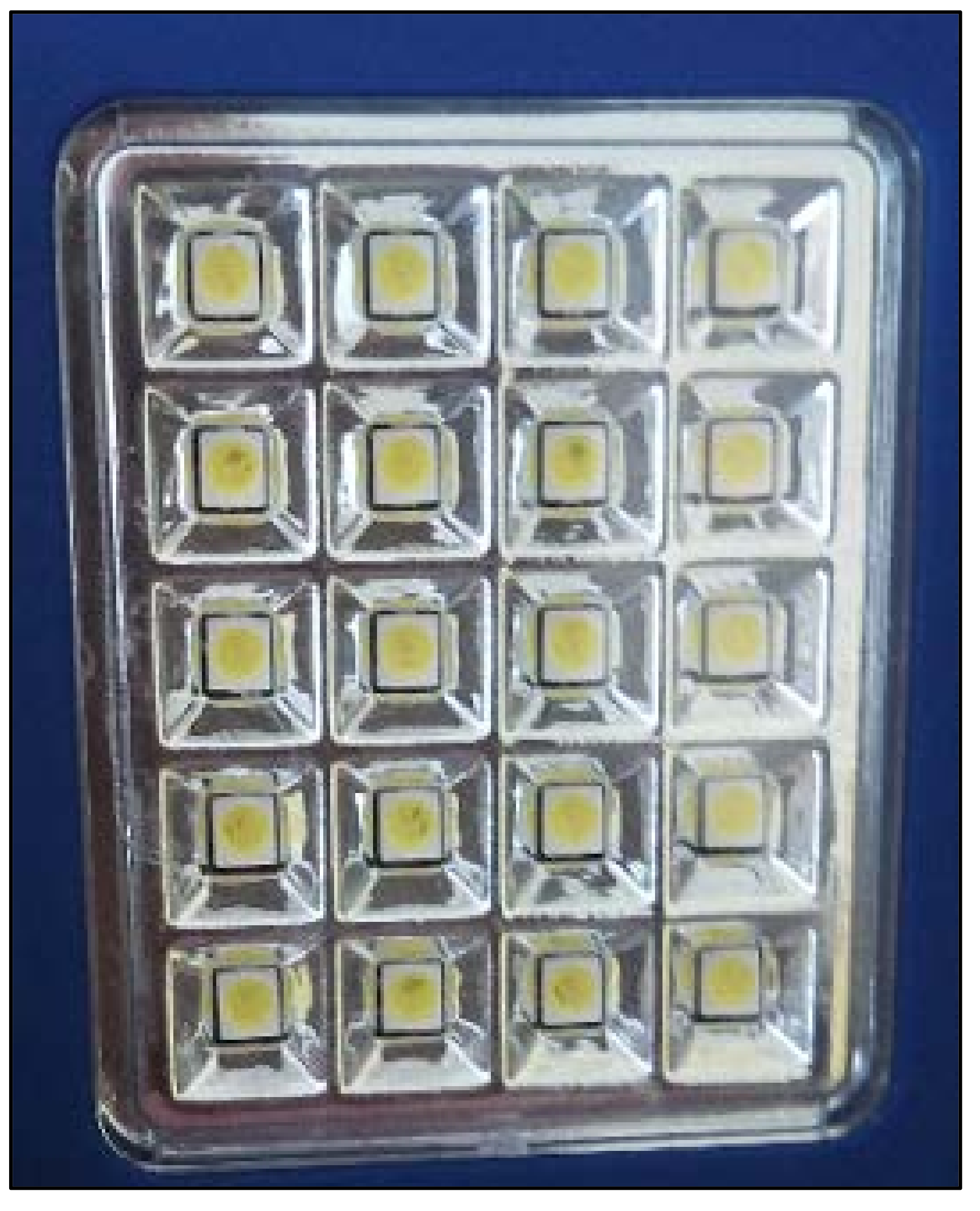
The final example in
Figure 14 shows the results of the same CCS2 socket, but in this example the scene is illuminated with two small SMD (Surface-Mount Device) LED (Light Emitting Diode) panels with 20 built-in LED diodes.
This example is very interesting, since the depth maps in
Figure 13 were not obtained well, and now the experiment is expanded with the use of artificial illumination source and the measurements were repeated. The expectation is, if the LED panel will highlight the textures of the socket, then the depth maps will be better. The illumination has been done simultaneously from the left and right sides of depth sensors, where the LED panels were placed in the same plain with depth cameras. In this position, the LED panels will not blind the camera sensors, and this is considered as a very important task in artificial lighting [
7,
16].
As it can be seen in
Figure 14, the use of artificial illumination source illuminates the scene and the textures of the socket with its surrounding are more visible in contrary to the images from
Figure 13. Obviously, the LED panels showed in
Figure 15 provide satisfactory lighting conditions, because in all the color images the scene is more clearly visible. Additionally, it can be noticed that RealSense cameras capture more colorful RGB images, while ZED cameras suppress the influence of the artificial lighting and their images contain less color. This phenomenon can be attributed to the different optics used by ZED cameras, compared to RealSense cameras. On the other hand, ZED depth sensors provide better depth maps, according to the results in
Figure 15. The first example was captured with D435 camera. As it can be seen, the frame of the CCS2 socket is poorly visible in the depth image, unfortunately it is not enough to be able to determine some of its details. The second example shows the results obtained with D415 camera. Here, the connector is not visible at all in the generated depth map. Even the use of lasers could not affect the generation of a quality depth maps with RealSense cameras in this experiment. The third example shows the result measured with ZED depth sensor. In the corresponding depth map some parts of the socket are recognizable and the frame of the socket is visible, however, the small holes in the socket are not visible. The final example presents the depth image obtained with ZED 2i depth sensor. As it can be seen, the socket is clearly recognizable in the depth map with all its parts. Obviously, the built-in polarizing lens compensated the light reflections caused by LED panels, which led to the generation of a quality depth map.
Based on the examples in
Figure 15, the ZED 2i depth sensor yielded the most accurate and realistic depth map in applications where the objects were illuminated with artificial illumination. As it can be concluded from example in
Figure 15, a quality illumination system can improve the visibility of the scene which leads to better noticeable textures in the RGB image. Thanks to the better visible scene, depth sensors can generate a depth map with greater reliability and quality.


 ,
, 


