Review

Motion Planning for Mobile Manipulators—A Systematic Review

by
Thushara Sandakalum
* and
Marcelo H. Ang, Jr.
Department of Mechanical Engineering, National University of Singapore, Singapore 119077, Singapore
*
Author to whom correspondence should be addressed.
Machines 2022, 10(2), 97; https://doi.org/10.3390/machines10020097
Submission received: 29 December 2021 / Revised: 22 January 2022 / Accepted: 24 January 2022 / Published: 27 January 2022
(This article belongs to the Special Issue Feature Papers to Celebrate the First Impact Factor of Machines)

Abstract

:
One of the fundamental fields of research is motion planning. Mobile manipulators present a unique set of challenges for the planning algorithms, as they are usually kinematically redundant and dynamically complex owing to the different dynamic behavior of the mobile base and the manipulator. The purpose of this article is to systematically review the different planning algorithms specifically used for mobile manipulator motion planning. Depending on how the two subsystems are treated during planning, sampling-based, optimization-based, search-based, and other planning algorithms are grouped into two broad categories. Then, planning algorithms are dissected and discussed based on common components. The problem of dealing with the kinematic redundancy in calculating the goal configuration is also analyzed. While planning separately for the mobile base and the manipulator provides convenience, the results are sub-optimal. Coordinating between the mobile base and manipulator while utilizing their unique capabilities provides better solution paths. Based on the analysis, challenges faced by the current planning algorithms and future research directions are presented.

1. Introduction

Mobile manipulator (MM) is a system created by mounting a robot manipulator on a mobile platform. Even though mobile manipulators are becoming popular only recently, the two main components—the robot manipulator and the mobile platform—have been popular for quite some time. From the first industrial robot Unimate #001 in 1959 [1], robot manipulators have developed significantly and have a vast range of capabilities. Mobile base robots have also come a long way since the first automated guided vehicle (AGV) in the 1950s, by Barrett-Cravens of Northbrook, Illinois (currently Savant Automation Inc., Walker, MI, USA) [2].
Robot manipulators have a wide range of uses across various industries such as space, health care, agriculture, military, and manufacturing. They have been used in factories for repetitive, dangerous tasks like welding, heavy object manipulation replacing human workers. These stationary robots were bulky and usually operated inside safety cells for the purpose of safety. Robot manipulators such as PUMA 560 by Unimation or 1000 kg—payload robots like KR 1000 titan by KUKA [3] have many Degrees of Freedom (DOF) allowing the robot to move its links to carry out a task like moving an object from one table to another (Pick-and-Place). Similarly, mobile base robots have also being used in various industry sectors, particularly in manufacturing facilities for product transportation. AGVs usually used lines marked on the ground for navigation. However, with the development in autonomous technologies, companies are moving away from simple guided vehicles towards autonomous mobile platforms which allow greater flexibility by using features from the environment to localize and navigate. They are more intelligent and capable of functioning within a more dynamic industrial environment comprising human workers. Compared with fixed routes of AVGs, autonomous mobile platforms are able to plan and execute paths on its own while avoiding obstacles which is far more efficient and time saving.
A robot arm has high manipulation capabilities but is limited in the workable area due to the stationary base. A mobile platform lacks the manipulation capabilities but has the ability to reach a wider work area. The mobile manipulator follows the ‘One Plus One Equals Three’ concept by combining capabilities of both the robot manipulator and the mobile platform while mitigating each component’s drawbacks. A mobile manipulator usually has 9 DOFs or higher (3-DOF mobile platform and 6-DOF robot manipulator), making the system kinematically redundant. These high capability robot systems have applications in flexible production [4], service [5,6], rehabilitation [7] and medical industries [8], military [9], as well as space exploration [10]. With an autonomous base, a mobile manipulator complements or replaces the work carried out by human workers independently requiring less human intervention. However, as these robot systems are now operating in complex, less structured, and dynamic environments potentially in close proximity with humans, unique challenges in system design, sensing, motion planning, and control emerge related to mobile manipulators.
These challenges have driven researchers to pursue various avenues when planning for mobile manipulators. The objective of this review is to discuss the motion planning techniques used specifically for mobile manipulators, identify current research progress, and formulate future research directions. Based on a systematic analysis, the advances made in the research studies are summarized and analyzed while giving insights. Researchers will be able to easily grasp the current research directions and state-of-the-art planning algorithms related to mobile manipulator motion planning.
While this article gives an in-depth analysis on motion planning algorithm for mobile manipulators, readers are referred to the work in [11] for an overview of challenges in mobile manipulation and to the work in [12] for a step-by-step tutorial on simulating an object fetch task using a mobile manipulator using Robot Operating System (ROS version 1). A list of publications with open-source codes can be found in Appendix A and the source codes are available on a GitHub repository (https://github.com/sandakalum/Mobile-Manipulator-Planning (accessed on 21 January 2022))

Contribution

It must be stated that reviews on mobile manipulator motion planning exist in the literature. Both [13,14] focus on benchmarking different motion planners using Moveit! [15]. A review on underwater manipulator motion planning was carried out in [13], while the authors of [14] reviewed path planning for KUKA KMR iiwa mobile manipulator’s arm. In both of these publications, the focus was mainly on comparing performance of few state-of-the-art planners rather than exploring the recent research work. A list of motion planners used for mobile manipulators was included in [16] but in-depth analysis was not included.
In this work, the current research was systematically surveyed to specifically find planning algorithms used for mobile manipulators. The special structure of the mobile manipulator creates unique challenges and the efforts by various researchers to address those challenges were summarized in this work. The planners were categorized into two categories which were specific to mobile manipulators rather than following the common categorization. The similarities and differences between different planners were also summarized. Different methods adopted to calculate the goal configuration for a mobile manipulator were extracted, which is one of the unique challenges for mobile manipulators.
The uniqueness of mobile manipulators and the impact on planning algorithms are briefly discussed in Section 1. The terminologies and common definitions used in planning algorithms are included in Section 2. Section 3 discusses the different planning algorithms used for mobile manipulator motion planning under two categories. Different methods of transforming a task space goal to a configuration space goal are evaluated in Section 4. An overall discussion on the planning algorithms is given in Section 5, and Section 6 concludes the article by discussing the available future research opportunities.

2. Common Concepts

It is important to have a good understanding about the common terminologies used in planning algorithms. The following section gives an introduction to the various terms and definitions used by motion planners.
  • Planning Space
    -
    Configuration Space (CS):Configuration of a mechanical system (composed of rigid bodies) uniquely specifies the position of every point in the system relative to a fixed reference frame [17]. A configuration q can be specified using a list of real values [18]. For a serial link manipulator arm, its configuration can be described using the joint values (either prismatic or revolute), i.e., q = ( θ 1 , θ 2 , , θ n ) , while for a mobile robot operating on a flat horizontal plane, its configuration can be described using two Cartesian coordinates specifying the position and one variable specifying the orientation, i.e., q = ( x , y , δ ) . If the parameters used to define a configuration are independent, i.e., the minimum number of parameters were used, those are called generalized coordinates of the system [19] and the number of parameters is called the degrees of freedom ( DOF ) of the system.
    If a configuration is considered as a point in some space, that space is called the Configuration Space C [19]. The dimension of the configuration space (N) is the number of parameters used to specify a configuration. For a mobile manipulator whose configuration is specified as q = ( x , y , δ , θ 1 , θ 2 , , θ n ) (Mobile base configuration q b = ( x , y , δ ) , Manipulator configuration q a = ( θ 1 , θ 2 , , θ n ) ), the configuration space is 3 + n with dimension (3 + n). The collection of configurations which does not collide with obstacles is called the free configuration space C f r e e while the configurations which collide with obstacles are members of C o b s t a c l e . The configuration space is the union of these two subsets ( C = C f r e e C o b s t a c l e ) and robot motions need to be in C f r e e .
    DOF of a robot refers to its control variables which helps to differentiate between DOF and configuration space dimension [20]. For example, a differentially driven mobile robot has three CS parameters but has only two DOF (Two controllable wheels).
    Joint space is interchangeably used to identify the configuration space.
    -
    Task Space (TS): The space at which the end effector (EE) of a robot operates in is referred to as the Task Space [21]. Cartesian Space, Operational Space, and End Effector Space are common names referring to the task space. Generally, Cartesian coordinates are used to specify the position of the end effector in 3 and the rotation group S O ( 3 ) for the orientation resulting in the task space 3 × S O ( 3 ) . An element in the task space is a M-dimensional vector where M is the maximum number of independent parameters required to specify the end effector pose (position and orientation) in the real world. Consequently, M 6 and M N .
    If M DOF of the system, such a system is called a kinematically redundant system. For example, a 4- DOF planar manipulator is a redundant system as the task space is 2 × S O ( 1 ) with M = 3 while DOF = 4 .
    The function f mapping a configuration q to a task space point X (Pose of the end effector) is called the forward kinematics (FK) function X = f ( q ) which depends on the kinematic structure of the robot. The calculation of a corresponding configuration for a TS point is called the inverse kinematics (IK) problem ( q = f 1 ( X ) ).
    -
    State Space: A state represents the status or condition of a robot. The State Space contains all the possible states that the robot can be in which are usually infinite. For example, it is possible to define a state for a manipulator by considering joint positions and joint velocities for which the state will be s = ( q , q ˙ ) = ( θ 1 , θ 2 , , θ n , θ ˙ 1 , θ ˙ 2 , , θ ˙ n ) .
    Path planning vs. Motion planning vs. Trajectory planning—A Path is a purely geometric function which specifies the change in robot’s state with reference to a scalar parameter s, varying from 0 to 1 with no reference to time ( C ( s ) or T S ( s ) ) [22]. Therefore, path planning results in a pure geometric description of robot’s motion. In motion planning, the change in robot’s state is expressed as a function of time t usually considering system kinematics including velocities and/or accelerations ( C ( t ) or T S ( t ) ) [22]. Trajectory planning and motion planning are used interchangeably but usually during trajectory planning, the time evolution of velocity and acceleration are also calculated.
    The basic path planning problem is to find a path specifying continuous sequence of robot’s states starting at the start/initial state and ending at goal/final state while avoiding obstacles [18]. Satisfying different constraints imposed on the robot complicates the planning problem. The goal state can be specified in CS or TS (TS is more common for real world applications).
  • Constraints There are various constraints that needs to be satisfied by the planning algorithm depending on the nature of the task and the robot’s mechanical design.
    -
    Collision: In the planning problem, collision avoidance is considered as a constraint as it limits the options for the robot. Robot colliding with environment obstacles as well as self-collisions (e.g., Manipulator of a mobile manipulator colliding with the mobile base or with the manipulator itself) must be avoided in the motion plan.
    -
    Physical constraints: These refer to the constraints applied due to the operational limits of the robot and the environment. Joint limits of the robot, torque limits of the actuators, and workspace area limits inside a room are considered under this category. Like collisions, these constraints cannot be violated by the motion plan.
    -
    Task constraints: These constraints are applied due to the nature of the task that the robot has to perform. For example, when the robot needs to transport an open liquid container, the container needs to be held upright to prevent spillage (this applies a constraint on the orientation of the end effector). Another example would be keeping the target object within the Field of view (FoV) of a sensor (camera, LiDAR) mounted on the robot. If the camera is mounted on the end effector (Eye-in-Hand), this constraint would limit both the position and orientation of the end effector.
    -
    Differential constraints: Kinematic constraints due to the robot structure (for example, non-holonomic constraint of a differently driven robot), velocity/acceleration/jerk constraints arising from system dynamics and robot’s stability constraints (tip-over stability of a mobile manipulator) are considered as differential constraints.
    These constrains can also be categorized as follows.
    -
    Geometric: Collision avoidance, Joint limits, Floor area limits
    -
    Kinematic: Non-holonomic constraints, Joint velocity limits, Joint acceleration limits
    -
    Dynamic: Joint torque limits, Tip-over stability
    -
    Kinodynamic: Both kinematic and dynamic constraints
  • Computational cost: Usually this refers to the time taken by the algorithm to calculate a valid solution to the planning problem. However, the memory requirement can also be considered as part of the computational cost especially for high-dimensional problems.
  • Completeness: A planning algorithm is said to be complete if it is able to find a collision-free solution whenever one exists while returning failure otherwise in a finite time [18]. These algorithms are mathematically more involved and usually build an exact representation of the planning space without loss of information. Therefore, these algorithms are usually difficult to implement. To solve this problem approximate methods were developed with weaker notions of completeness. A resolution-complete algorithm would find a solution in finite time if the resolution used to discretize the planning space is arbitrarily small to capture the relevant information. However, if these is no solution, the algorithm may run indefinitely [18]. For a probabilistic-complete algorithm, if a solution exists, the probability of finding a solution will tend to 1 as more time is spent on the planning problem exploring the planning space [23]. These algorithms trade completeness with computational cost.
  • Offline vs. Online If a planning algorithm is calculating the motion plan based on the information available at that time and does not conduct any modifications even when new information is available it is considered an offline motion planner. In contrast, if a planning algorithm is able to generate a completely new plan or update a previously available plan in real-time as new information is made available it is an online planner.
  • Optimality: A planning algorithm can generate a feasible plan while optimizing a defined criteria. This criteria can include a cost which needs to be minimized referring to distance traveled (in CS or TS), energy usage, execution time, or a measure which needs to be maximized such as distance to obstacles, path smoothness and manipulability measure of a robot arm. It is also possible to calculate a weighted average of all/several of these measures as the cost to be optimized.
  • Robustness
    -
    Dynamic environment: There are two instances of a dynamic environment: (1) Environment changes with time—In this dynamic environment, there will be multiple moving obstacles with known or unknown trajectories. (2) The robot has limited (partial and/or uncertain) knowledge about the environment at the beginning, and this knowledge will change introducing dynamism to the robot’s planning environment. A planning algorithm is said to be robust against dynamic environments when the planner can maintain the same performance level even when the environment changes.
    -
    Uncertainty: In the real world, there are various uncertainties introduced by the imperfections and limitations of the sensing/actuating mechanisms. Sensor noise, actuation errors, dynamic modeling errors, and approximation errors all contribute to the uncertainties of a robot system [24]. Most planning algorithms require a perfect knowledge about the environment and also assume that a robot is able to perform an action with a deterministic outcome. However, this is not a valid assumption when operating in the real world. For example, due to the slipping between the wheel and the floor, a mobile robot may not move as expected. To deal with the effect of these uncertainties, probabilistic robotics explicitly model the uncertainties using calculus of probability theory [24] which can be used in planning algorithms.

3. Motion Planning Algorithms for Mobile Manipulators

Mobile manipulators are high DOF systems with complex constrains and system dynamics. In most scenarios, mobile manipulators become kinematically redundant due to the high DOF. This redundancy allows the system to be flexible when operating in complex environments but complicates the planning process as there are infinite solutions to the inverse kinematics problem. Further, the mobile base and manipulator have significantly different dynamic characteristics because the mobile base has a higher inertia than the manipulator. However, these two systems are strongly coupled resulting in complex dynamic behaviors. Both of these characteristics compound the planning problem complexity.
There are various approaches taken to solve the motion planning problem of mobile manipulators which are summarized below. The planning algorithms are divided into two broader classes depending on the treatment of the whole system, i.e., whether the planning algorithm consider the behavioral differences between the mobile base and the robot manipulator or not.

3.1. Two Subsystems—Separate Planning

Often, a complex task is divided into sequence of sub-tasks and planning is carried out for each sub-task separately which essentially decouples the planning for the mobile base and robot manipulator. Various planning algorithms are available in the literature for mobile base [20,25,26,27,28] and manipulator [29] planning, but those were not specifically implemented on mobile manipulators. When motion planning was carried out separately for the mobile base and the manipulator, the prevailing algorithms for the mobile base [20,25,26,27,28] and the manipulator [29] can be used after deciding on a goal configuration for the mobile base and for the manipulator (Figure 1). This section analyzes planning algorithms where the plans for the two subsystems were carried separately.
In [30], the authors proposed Receding Horizon Task and Motion Planning (RH-TAMP) algorithm which used RRT-Connect for the manipulator planning, while the mobile base planning was carried out using Djikstra’s algorithm. The task of transporting a colored cylinder from one table to another was realized using a mobile manipulator where the goal configurations were calculated using a geometric reasoning module. The geometric reasoning module calculated the mobile manipulator’s configuration using inverse kinematics and verified the feasibility by carrying out collision checks.
Saoji et al. [31] used RRT-Connect for motion planning of both the manipulator and the mobile base but the planning was carried out separately. For the task of pick-and-place task, the goal for the mobile base was pre-recorded while the manipulator goal configuration was selected from pre-calculated two end-effector poses based on collision.
Dijkstra algorithm was used in [32] for the mobile base planning. The pick-and-place task was realized by identifying the task space goals using a stereo camera. The manipulator motion was planned through four key points (Observation point, Reach point, Grasp point, and Unload point) which were selected from a database based on the object to be grasped.
Rastegarpanah et al. [33] used the A* algorithm for mobile base planning while RRT was used for manipulator planning. The task of picking up objects from a table and returning them to relevant bins was realized using a mobile manipulator. The mobile base locations for object pickup and object unload were pre-recorded and the best pose was selected based on the Euclidean distance from the current mobile base pose. The A* algorithm used this as a goal configuration for the mobile base.
OMNIVIL—a mobile manipulator—was developed by Engemann et al. [34]. The mobile base motion was planned using A* or Dijkstra algorithm while the manipulator motion was planned using RRT-Connect.
In [35], the authors used the A* algorithm for mobile base planning while the manipulator motion was planned by simple interpolation and curve fitting. The mobile base goal was pre-calculated and the goal poses for the manipulator were selected from two pose collections. The manipulator goal pose selection was done after identifying the goal regions from the environment using a deep learning technique.
In [36], the authors used a Cubic Benzier spline to plan the mobile base path to reach a task space goal. After mobile base goal configuration was calculated (considering manipulator’s reachability), different paths were calculated considering obstacle avoidance, velocity limit, and acceleration limit. The best path was selected based on the path length and path curvature (Equation (1)). During the mobile base motion, the manipulator was kept stationary. The sequential nature of the method allows the path to be updated in real-time when more sensor data are available.
P a t h _ c o s t = k l e n g t h 0 1 x ( s ) 2 + y ( s ) 2 d s + k c u r v a t u r e 0 1 | x ˙ ( s ) y ¨ ( s ) x ¨ ( s ) y ˙ ( s ) | ( x ˙ ( s ) 2 + y ˙ ( s ) 2 ) 3 2 d s
where x ( s ) and y ( s ) are Cartesian coordinates of the mobile base path with x ˙ ( s ) , and x ¨ ( s ) represent the first and second derivatives with respect to the scalar parameter s. In [37], the authors proposed three different local planners (an intuitive planner, a barycentric planner, and a chained planner) for the mobile base path which were used depending on the goal mobile base orientation and the distance from the start position to the goal position. The manipulator configurations were simply calculated by iteratively adding a portion of the difference between the start and goal configurations along the path.
Akli et al. [38] further improved the random profile approach (RPA) concept by considering manipulability (using Inverse condition number [39] (Equation (2)) of the manipulator as an additional constraint while specifying a goal position in the task space.
c ( q a ) = 1 c o n d ( J ( q a ) ) = s n s 1
where s 1 and s n are the largest and smallest singular values of the Jacobian matrix. The algorithm first calculated the mobile base motion for the goal Cartesian coordinates (randomly sampled within a bounded region about the task space goal) and verified that the task space goal was reachable. Then, the goal configuration was accepted only if the current inverse condition number was greater than a threshold. Finally, the manipulator motion was planned for the calculated goal configuration using a B-splines.
Iriondo et al. [40] used a deep reinforcement learning model to generate the mobile base behavior. The RL model was able to drive the mobile base to a location such that the manipulator can carry out the pick-up task. Even though the algorithm was able to successfully execute tasks, these algorithms were not robust due to the unstable nature of the algorithms.
For the task of picking up an object while the mobile base is moving, Shan et al. [41] proposed to plan the mobile base path considering the manipulability index [42] distribution. The authors calculated the manipulability index distribution on two z-axis heights (at object height and at object pick up pose height). The resulting distributions were again filtered to have a minimum manipulability threshold and intersection was taken. A simple straight-line path was drawn on the resulting distribution, which ensured that the manipulator will have the capability (due to high manipulability) to account for the errors in mobile base placement during task execution. The path of the manipulator was planned using inverse kinematics.
Unlike in [36], the manipulator and the mobile base were moved simultaneously in [37,41] but those two motions were completely decoupled. Even though this allowed the use of available algorithms to be used for each subsystem, the capabilities of the mobile manipulator were not fully utilized.
The above algorithms planned for a single goal, while planning to follow a given EE (end effector) trajectory is summarized below. When it is required to calculate the CS path for a given EE trajectory, usually the motion of the mobile base or the manipulator was planned first, and then kinematic relations were used to calculate the path of the other.
In [43], the authors first decided the manipulator configurations. Zhao et al. [43] used the Genetic Algorithm (GA) with the cost related to squared Euclidean distance in mobile base configuration space to calculate the manipulator configurations for multiple EE poses while considering joint limits, torque limits, EE pose error, and force applied at EE. However, this method was not applicable on non-holonomic mobile bases. Jiang et al. [44] used a Self-Adjust Genetic Algorithm to calculate the intermediate configurations for a given EE trajectory. This method was implemented on a redundant manipulator arm where one joint angle was calculated to minimize the joint movements while kinematics relations were used to calculate the remaining configuration parameters. The Self-Adjust Genetic Algorithm improved convergence speed and optimization accuracy over generic Genetic Algorithm.
In [22,45,46,47,48,49,50,51,52,53], the mobile base motion was planned first. The path planning technique proposed in [48] calculated the mobile base locations for a given EE path such that the number of mobile base poses is minimum. The authors calculated the longest EE path segment that the mobile manipulator can follow without moving the mobile base and removed that segment from the EE path and start the same process again. For this, a cost considering the reachability (Inverse kinematics solution is available) and directional manipulability (Manipulability tangent to the EE path) was maximized.
The work in [37] was improved to follow a given EE trajectory in [22]. From the mobile base start configuration, the incremental change needed in configuration space relating to a change in EE path was calculated using Reduced Inverse Differential Kinematic Model (RIDKM). The RIDKM model included only independent parameters after accounting for the dependency due to the non-holonomic mobile base. The manipulator configurations were simply calculated by iteratively adding a portion of the difference between the start and goal configurations along the path.
Aarno et al. [49] used attractive forces (dependent on the distance between the base and the given EE) applied by the EE pose and repulsive forces (force on arm links due to distance from obstacles were transformed to mobile base using kinematics) applied by the obstacles to plan the mobile base path for a given EE path. The weights for each force were chosen such that the EE pose was within reach of the manipulator. Inverse kinematics was used to calculate the intermediate manipulator configurations.
Papadopoulos et al. extended their work presented in [54] (related to collision avoidance) to consider the whole mobile manipulator for collision avoidance [55] and further extended to consider polygonal obstacles and trajectory-known obstacles [50]. To make sure that the mobile base was positioned such that the EE position is reachable, for each EE position, the mobile base position bounds were assumed as a circle with radius defined by manipulator link length. Then, these bounds were considered as a virtual inverse obstacle and used in mobile base path planning to ensure each EE was reachable.
In [51], the mobile base poses were determined using the Genetic Algorithm. Few key points were sampled from the discretized EE path for which the mobile base pose was calculated using GA to minimize the mobile base rotations, traveling distance, and manipulator joint velocities (Equation (3)).
C o s t = w b _ r o t t = 1 n | δ ( t i + 1 ) δ ( t i ) | + w b _ d i s t = 1 n ( x ( t i + 1 ) x ( t i ) ) 2 + ( y ( t i + 1 ) y ( t i ) ) 2 + w a r m q a ( t i + 1 ) q a ( t i ) t i + 1 t i
where w b _ r o t , w b _ d i s , and w a r m are weighing scalar parameters with t i is a time instance. More weightage was given to joint velocities to obtain smooth motions. Linear interpolation was used to plan the motion between calculated mobile base poses. Finally, inverse kinematics was used to calculate the manipulator configurations (previous manipulator configuration was given as a seed to the IK algorithm to generate solutions with small joint angle changes).
Dong and Zhao [52] first planned the mobile base path (in Cartesian coordinates) using the Genetic Algorithm where the cost function accounted for the distance traveled and obstacle collision. The same optimization algorithm was used for calculating the manipulator configurations and mobile base orientation while minimizing joint angle change, orientation change and maximizing manipulability.
Both in [51,52] the smoothness of mobile base path was considered implicitly by minimizing the mobile base orientation change. However, in [53], the mobile base path was represented using a Cubic Benzier spline and during optimization, maximum allowable path curvature was explicitly considered. Hu et al. [53] used the Particle Swam Optimization Algorithm (PSO) to calculate the mobile base path for a given EE path. The cost to be optimized contained information related to the uncertainty of localization, maximum allowable path curvature, and minimum allowable manipulability index. The reachability of EE during the path was guaranteed by maintaining a lower bound on the manipulability index.
Chitta et al. [56] proposed a method to plan the motion of a mobile base to open a door. The goal configuration for the mobile base was not specified rather the constraint that the EE should be able to stay on the door handle was specified. The mobile base motion graph was created in a 4-dimensional state space (mobile base pose and binary value encoding the state of the door) by using motion primitives to generate transitions (lattice-based representation [57]). The state of the door was represented using a binary variable [0, 1] which represented the motion range of the door while the goal state of the door was easily represented using value 1. A path through the graph was found using Anytime Repairing A* (ARA*) [58] algorithm with the cost accounting for the distance to obstacles on a 2D projected costmap and manipulator comfort (distance between the door handle and the shoulder of the manipulator). The heuristic cost to the goal was the amount by which the door needs to be opened to be considered fully open. The manipulator path was planned using sampling based planners introduced in [59].
In [60], the authors developed a framework for pick-and-place tasks using mobile manipulators and validated it using the PR2 mobile manipulator. The complete task was divided into three sub-tasks—pick, transition, and place, while motion planning for the mobile base and the robot manipulator was decoupled. During the pick phase and place phase, robot arm motion was planned using sampling based motion planners. Planning was carried out in the task space due to the ease of generating constraint motion (Gripper orientation constraint if the object contains liquid). Further, post-smoothing processing was done on the path using cubic splines to satisfy velocity and acceleration bounds. The transition phase mobile base motion was planned using a method introduced in [61] which used Anytime Repairing A* (ARA*) for path planning while collision checking was done using a Multi-Layered 2D Obstacle Map. Motion planning for the mobile base did not account for the manipulator movement while the base was in motion.
All the above planning algorithms did not consider the tip-over stability of the mobile manipulator. Huang et al. [45,46] planned the mobile base trajectory by formulating the problem as a nonlinear optimization problem considering the minimum mobile base acceleration, ability to reach EE (Circular boundary about EE position) and system stability (as a velocity limit on curved path segments) and solving it using a gradient projection method. Then, manipulator configurations were calculated maximizing manipulability [42]. In [47], the authors followed the same procedure except the manipulator configuration were calculated to make manipulator’s static potential energy low (elbow at its lowest point and the wrist directly in front of the shoulder). Unlike previously stated planning algorithms where the tip-over stability of the system was assumed to be satisfied during the whole EE trajectory, in [45,46,47] the planned motion was modified (using Runge–Kutta method) based on Zero Moment Point (ZMP) [62] trajectory which was a measure of tip-over stability.
Table 1 summarizes the different algorithms used when planning to follow a given EE trajectory. Once a task is divided into sub-tasks, mobile base placement is especially important as it affects the subsequent manipulation tasks. Poor base placement may even render the final goal state unreachable. One main issue with this approach is the sub-optimality of the generated solution paths. Even though it is possible to generate optimal solutions for each sub-task, collection of those solution does not necessary results in a global optimal solution. The goal state of the previous sub task will greatly affect the planning of the next task and may even prevent from generating a feasible solution creating the need to re-plan the previous task. Therefore, this approach will result in either locally optimal, globally sub-optimal paths or high number of unsuccessful motion planning queries.

3.2. Combined System with High DOF

Manipulation planning for the entire task would alleviate the issues of global sub-optimality, but this is highly computationally intensive. Motion coordination between the mobile base and the manipulator, collision checking with the environment and self-collision checking, motion constraints are some of the added complexities that are seen in this approach.

3.2.1. General High DOF Planning

Planning algorithms that are capable of dealing with high dimensions were used for mobile manipulators where the whole system was considered as a single system despite the behavioral difference of the mobile base and the manipulator.
Brock and Kavraki [63] calculated the free space representation as a swept volume (Tunnel) using wavefront expansion algorithm and used a local minima free potential field function to find a path through the tunnel. This method sacrificed completeness for real-time performance while guaranteeing a minimum safety distance to obstacles. This algorithm was validated on a free-floating mobile manipulator which made it applicable for holonomic wheeled mobile manipulators.
Su and Xie proposed the Representation Space (RS) in their work in [64] which is a space spanned by the attributes of the robot system and the given task. CS and TS can be considered as subsets of RS where even a link length of a manipulator can be one of the variables in RS. The authors explicitly calculated RS (Discretized each dimension and checked for validity at each point then recorded whether the point is valid or not) and carried out motion planning using A* algorithm. In [65], A* algorithm was used on RS where the heuristic cost was calculated as the Euclidean distance from current node to goal.
Both above algorithms calculated a representation of the free space which was computationally expensive and the representation needed to be updated if the environment was dynamic. Rather than explicitly calculating the free space, it is possible to create a graph which spans through the free space which is computationally efficient.
Gochev et al. [66] proposed a graph-creating algorithm which used Anytime Repairing A* (ARA*) for state transition graph searching. Here, the idea was based on adaptive dimensionality where a discretized finite state space graph G a d was built and queried for a path. G a d had both low-dimensional (3D-TS) regions and high-dimensional (11D-CS) states and transitions. G a d started as a low-dimensional graph and high-dimensional regions were added iteratively. When adding high-dimensional regions, the low-dimensional states and transitions in the overlapping regions were replaced with their high-dimensional counterparts. State transitions between low-dimensional states and high-dimensional states were replaced as follows. If the state was already in G a d , then the other state was converted to match the dimension and the edge between those two states was added to G a d . Then, the graph was searched for a suitable path and if a path was found, all the states and state transitions were converted to high-dimensional components while if a path was not available, G a d was updated by adding another high-dimensional region. This approach was slower than sampling based planners but bounds on sub-optimality and guarantees on completeness were attractive characteristics.
Kinodynamic Planning by Interior-Exterior Cell Exploration (KPIECE) [67] iteratively constructed a tree in the state space of the robot. From the initial state, the transitions were calculated using a physics simulation engine (increased accuracy, convenient model construction outweighed the increase in computational cost). The tree expansion was guided by the discretization (a grid) of a projection of the state space. The priority of expansion was given to grid boundaries which were less explored. This algorithm was implemented on a mobile manipulator in [68].
When motion planning is considered as a trajectory optimization problem, the goal is to find a trajectory that minimizes a given cost function while satisfying the constraints (Note: Even though some of these algorithms were not implemented on a mobile manipulator, those were included for completeness.). Covariant Hamiltonian Optimization for Motion Planning (CHOMP) [69] used covariant gradient descent (non-stochastic) to minimize a cost function which encoded path smoothness (squared velocity) and obstacle collision (calculated using a precomputed signed distance field) to transform a simple trajectory to a collision-free executable trajectory. The joint limit constraint was satisfied by projecting the joint values to an acceptable range when a violation was detected.
Stochastic trajectory optimization for motion planning (STOMP) [70] also used optimization to find suitable trajectories. This algorithm used a derivative-free stochastic optimization technique to update a series of noisy initial trajectories. The cost function contained information on obstacles (similar to CHOMP), EE position and/or orientation constraints (cost for violating constraints), and joint torque constraints (Magnitude of torque). The joint limit was considered when generating initial trajectories and due to the convex nature and the smoothing, joint limits were not violated during optimization.
Both CHOMP and STOMP used large number of states to represent a trajectory so that the optimizers were able to safely navigate obstacles while ensuring smoothness.
TrajOpt [68,71] tried to account for this problem by considering swept volumes for collision checking which allowed to use sparsely sampled trajectory. The optimization was done with numerical sequential convex optimization with cost being the Euclidean distance in configuration space (encourage minimum-length paths). This algorithm was capable of handling non-holonomic constraints as well.
Gaussian Process Motion Planner (GPMP) [72] considered the joint space trajectory (position, velocity and acceleration) as a sample from a vector-valued Gaussian process (GP). This allowed the smooth trajectories to be represented with few states while facilitating the use of Gaussian process regression to calculate robot state for any time of interest. The GP was generated by the linear time varying (LTV) stochastic differential equations (SDEs). The gradient-based optimization was used to minimize the trajectory displacement from the prior mean (keep the trajectory smooth) and obstacle cost (This definition was similar to that of CHOMP [69] which promoted circumventing obstacles rather than passing them quickly).
Gaussian Process Motion Planner 2 (GPMP2) [73] solved the trajectory planning problem using probabilistic inference. This formulation required the user to find a maximum a posteriori (MAP) continuous-time trajectory given the prior distribution (The authors represented the continuous-time joint trajectories as samples from Gaussian Process (GP) [72]. A Gaussian RBF kernel was used to define prior distribution of trajectories.) and a likelihood function (encoded information about obstacles, start and goal). The MAP estimation problem was then solved using nonlinear least square optimization algorithms (gradient-based) such as Gauss–Newton or Levenberg–Marquardt. This algorithm was implemented on a complete mobile manipulator in [74].
Simultaneous trajectory estimation and planning (STEAP) [74,75] was an improvement from Gaussian Process Motion Planner 2 (GPMP2) [73] where the likelihood function not only considered collisions, start and goal but also the sensor measurements. The authors specifically defined the configuration space of a mobile manipulator by a Lie group product x S E ( 2 ) × n where S E ( 2 ) Lie groups defined the Cartesian coordinates and yaw angle of the mobile base while n was the DOF of the arm. By incorporating the sensor measurements, better state estimation was achieved which helped to generate better trajectories over GPMP2.
Gupta and Lee [76,77] proposed a global path re-planner which used Sequential Quadratic Programming for optimization. Straight line path through way points was planned in the task space and a local planner generated the joint trajectories to follow the EE trajectory. If the joint limits were violated during the trajectory generating process, a small deviation at the point of failure was introduced to the task space trajectory. In calculating this deviation, the authors used Sequential Quadratic Programming to minimize the deviation from the desired trajectory while satisfying joint limits.
Sampling-based planners (RRT [78], PRM [79,80], and EST [81]) and their variants (RRT-Connect [68,82,83], RRT-GoalBias [78,84], Informed RRT, Bidirectional Informed RRT, RRT* [85], Bidirectional RRT* [86], Informed RRT* [87], and Constrained Bidirectional RRT (CBiRRT2) [88])) have been used for mobile manipulators where the whole system is considered as one high DOF system during the planning process due to planer’s ability to deal with high-dimensional spaces.
In [89], the RRT algorithm was used with a modification to the local planner where at each iteration, the local planner varied the step length made towards the sample point from the nearest neighbor based on the current lowest path cost and the approximate lowest path cost.
Seyboldt et al. [90] used the RRT algorithm with the goal specified in the task space. The distance between the task space goal and a node in the tree was calculated by transforming the tree node into the task space using forward kinematics. This distance was used as a heuristic to guide the exploration towards the goal pose. However, as it was not guaranteed to reach the goal pose, tree nodes which were closer to the goal pose were selected, and a direct connection between the tree node and goal pose was attempted using the Jacobian matrix.
A novel sampling-based planning algorithm named XXL was proposed by Luna et al. [91] where robot’s workspace information was used to guide the planner through the high-dimensional planning space. Even though this method was not tested on a mobile manipulator, the authors state that this algorithm was specially designed to plan the motions of high-dimensional mobile manipulators and related platforms. Here, the robot’s workspace was decomposed, and an informed sampling strategy was developed such that it was possible to generate samples which explicitly projected onto a particular workspace region. However, if the solution was a simple straight-line path, using XXL would be a waste of resources, as XXL had high computational overhead owing to the projection scheme and workspace decomposition.
Several authors have tried to mitigate the inherent issues of sampling based planners using different techniques. In some applications, there were task constraints (e.g., follow a given end effector trajectory) that needed to be satisfied. One approach to address this constraint for sampling based planners was to project (using randomized gradient descent, tangent space sampling or retraction [92] for articulated manipulators) the random samples onto a sub-manifold which satisfied the task constraint with an acceptable error tolerance.
Another approach was to generate samples by first selecting a task space point from the desired task path and calculating the configuration using inverse kinematics [93]. This method was further supplemented by using a Jacobian-based equation of motion with motion primitives for motion generation from a selected node which ensured continuous task constraint satisfaction. In [94], the authors further improved their method by considering dynamic obstacles with known trajectories in the environment. For this, the authors proposed using the RRT algorithm in the task-constrained planning space augmented with the time dimension. Cefalo et al. further improved their method in [95] where the planner satisfied the task constraint exactly (hard constraint) whenever possible while being capable of exploiting the available constraint tolerances (soft constraints) when needed. In [95], the authors proposed a heuristic to identify the nodes at which the hard constraint satisfaction was no longer feasible (number of vertices on the frontier leaf (indicate that frontier leaf has been sufficiently explored) and number of failed expansions (indicate that sufficient number of extensions have been attempted, i.e., kinematic redundancy has been fully exploited)) and becomes feasible again (number of collision free configurations out of randomly generated configurations on the next leaf). However, these methods only considered the end effector position as a task constraint not the orientation.
Zhu et al. [96] proposed a method to generate paths online for a mobile manipulator. A large database of paths was generated offline (using CBiRRT2 [88]) (Database included start and goal configurations, generated paths, swept volume of the robot, and environments.) and during the online path generation phase, the start configuration and the goal configuration were extracted from the database based on a nearest neighbor search. Then, for those start and goal configurations, a path (or a combination of paths) was selected from the database using A* algorithm. The path from the approximate goal to the actual goal was separately planned (can be done in parallel once the approximate goal was decided to speed up the algorithm). For fast collision checking, swept volume of the robot along the planned path was used. Even though this method allowed for online path generation, significant offline date generation was needed to build a sufficient database while the generated path quality directly depended on the quality of the database.
Task Space RRT (TS-RRT) [97] was introduced by Shkolnik and Tedrake where the nodes contained both the task space information and configuration while the sample generation, nearest neighbor search and path extend were done in the task space. Heuristic map-guided TS-RRT (HM-TS-RRT) [98] was an improvement of TS-RRT where a heuristic map of the task space was used to guide the exploration (The nearest neighbor was selected from a set of nodes whose heuristic value is low.) instead of just pure exploration. The heuristic map represented the distance to the goal and distance from obstacles. The map was calculated using a 3D-CNN architecture named Heuristic Map Networks (HMNet).
In [99], the authors used a modified version of RRT-Connect to plan mobile manipulator motions. Along with the conventional approach to connecting the two trees, the authors proposed to extend the two trees along a linking line between the two trees. This greatly reduced the number of nodes.
Yang et al. [100] proposed a modified RRT-Connect planner which plans in the configuration space augmented by time. This was a geometric planner whereby adding the time dimension, the joint velocity was considered implicitly during the planning stage. The planner was capable of generating motion plans for moving object grasping but the object trajectory needed to be known in advance. The time dimension of a generated sample was modified if there was no valid nearest neighbor that could be reached while satisfying joint velocity limits.
These sampling-based planners are capable of finding solutions but the path quality in terms of smoothness can be low resulting in jerky motion of the system. To deal with this issue, various smoothing techniques have been proposed but this is less effective in cluttered environments. Shao et al. [84] proposed a postprocessing technique for a path generated by RRT-GoalBias [78] where motion between two non-adjacent nodes was replaced with a linear motion discarding the intermediate nodes provided that the linear motion was collision free. Further, sampling-based algorithms are only probabilistic complete and may provide different solutions during different runs due to random nature.
While the above algorithms were capable of generating a path, they did not consider the dynamic limitations of the system. Both works in [101,102] considered the system dynamics in order the limit the actuator torques.
Haddad et al. [101] adapted the Random Profile Approach (RPA) [103] which was proposed for fixed base manipulators to mobile manipulators. This method was capable of handling dynamic constrains (active joint torque bounds) along with collisions and other physical constraints. This trajectory optimization method calculated time-scaled trajectory profiles where the trajectory time was bounded by the kinodynamic constraints. To do this, the problem was reduced to a single parameter profile optimization problem and solved using simulated annealing method. This method required an initial trajectory to be planned using another method, and the optimized trajectory belonged to that homotopy class.
Continuous Clonal Selection Algorithm based on wavelet mutation (CCSA-WM) was used to minimize the joint torques in [102]. The joint torques were represented using a 5th order polynomial which were mutated using a Artificial Immune System (AIS) Algorithm. At each iteration, the system’s state was calculated by applying the joint torques on the system’s dynamics equation. If the desired goal state was not reached, the authors suggested to divide the final time segment into two (break point decided by AIS) and calculated a separate polynomial from the break point to reach the exact goal state (This was possible as the break point state values were not fixed.).
In [104], the trajectories were sampled from a Gaussian process (GP) but the optimization cost only encoded information about collision avoidance. Authors stated that it was possible to consider additional cost items such as task constraints, joint torques, and manipulability. The cost was optimized using a derivative-free cross-entropy stochastic optimization algorithm which was less prone to local minima than gradient based algorithms. This method allowed the algorithm to store a smaller number of states while facilitating parallel processing for speed.
Evolutionary strategy rather than Genetic Algorithm was used in [105] to plan a EE trajectory. The trajectory was modeled as a B-spline, and the data points for the B-pline were calculated using Evolutionary strategy which considered motion smoothness (squared integration of time derivative for each joint torque), joint limits, manipulator singularity, and stability (zero-Moment Point (ZMP) [106]). This was implemented on a non-redundant mobile manipulator, but the authors suggested that it can be extended to redundant manipulators easily.
Abdessemed [107] formulated the forward kinematics equation of a mobile manipulator as a pseudo neural network and used that to calculate the configurations for a given EE trajectory. At each time, the previous time stamp’s configuration was used as input to the network to calculate the EE position. Then, EE error (Euclidean distance by comparing with the required EE position) was calculated and back propagation was done to update the weights (using Levenberg–Marquardt algorithm). Then, the input vector was multiplied with the updated weight vector to get the next time stamp’s configuration. This algorithm was applied on a redundant robot but only EE position was considered.
Sequential Expanded Lagrangian Homotopy (SELH) approach proposed in [108] sequentially calculated the configurations for a given EE path. The algorithm calculated the configuration for each point in the discretized trajectory by optimizing manipulability index [42] using SELH where the algorithm used the knowledge from the previously calculated configuration in the next configuration calculation. This method was able to easily integrate collision avoidance, soft task constraints, and dynamic obstacles (as the problem is solved sequentially); however, the final solution quality significantly depended on the start configuration (Calculated offline to get several good guesses).
In [109], performance of different metaheuristic algorithms was compared when generating the configurations for a given EE trajectory. The authors used a cost function which accounted for the EE error, distance from the previous configuration, and a penalty term for violating joint limits. Different algorithms (CS—Cuckoo Search, DE—Differential Evolution, HBBO—Human behavior-based optimization, PSO—Particle Swarm Optimization, and TLBO—Teaching-Learning-Based Optimization) were implemented and simulated. The authors concluded that DE algorithm outperforms others with respect to the cost and computational time.
Costanzo et al. [110] used a mobile manipulator for the task of shelf replenishment. A new grasp pivoting method was introduced which allowed the gripper to change the grasp configuration without re-grasping the object. This effectively added another constrained DOF to the robot and required a planner capable of efficiently handling constraints. Authors used the learned action generation models proposed in [111] to plan for the 10-DOF system (Mobile base—3, Manipulator—6, Gripper virtual joint—1).
Reinforcement Learning (RL) techniques was used in [112] for mobile manipulator pick-up tasks. The planning was carried out in the state space which encoded the position of the gripper w.r.t the robot base frame, the position of object w.r.t the gripper frame, the position of object w.r.t the robot base frame, the joint positions and velocities of the arm, as well as the gripper state. The RL module was trained using Proximal Policy Optimization (PPO) algorithm. The RL model was able to calculate the EE position actions, mobile base pose actions, and gripper action which were required to pick-up an object from a random pose.
Summary of motion planning algorithms discussed in this section is included in Table 2 (properties of these planners are summarized in Appendix B.1). Motion planning in the high-dimensional space is not only computationally expensive, but also the generated paths can be of low quality. Due to the randomness of the sampling based planners, there may be unnecessary motions of the manipulator even after post smoothing processes. In most cases, it is sufficient to move the mobile base only, the manipulator motion is required only at certain base poses. These issues can be solved by coordinating the two subsystems.

3.2.2. Two Subsystems—Different Capabilities

The information about the different characteristics of the two subsystems can be used for making planning decisions.
Perrier et al. [114,115] proposed to use dual quaternions to represent a robot’s state where the non-holonomic motion of the mobile base was represented as a constrained displacement in the quaternion space. The motion planning problem was reduced to just iteratively moving the mobile manipulator towards the goal in planar quaternion space. Even though this approach was associated with simple matrix arithmetic, the planned path needed to be transformed from the quaternion space to configuration space. One of the main advantages of using dual quaternions was the insensitivity to measurement units as opposed to using homogeneous matrices.
A motion graph was built in [116] by sequentially applying motion primitives on the system (similar to the work in [117]). From the start configuration, forward motion of the mobile manipulator was obtained by applying several control inputs to the system. Then, a node was selected based on a metric and motion primitives were applied again. The number of acceptable control inputs was termed as Feasible Acceleration Count (FAC) where those control inputs were calculated such that the mobile base was always in contact with the ground and the friction cone constraint was satisfied for the wheel–ground contact (tip-over stability). The next node to be extended was selected based on the FAC and the geodesic distance to the goal. This algorithm was applied on a system navigating on an uneven terrain which showed the planner’s ability to keep the mobile manipulator stable without tipping over.
In [118], the authors used the FAC in conjunction with a RRT-like algorithm. The control inputs available for the local planner to extend from a particular node were selected for the collection of Feasible Accelerations. In selecting a node to be extended from, rather than using the closest node to the random configuration, a node with the highest ratio of FAC to geodesic distance to the goal was selected. Because of this, stability and maneuverability of the robot was promoted in an uneven terrain.
Lamiraux et al. [119] proposed an extension of RRT algorithm to be used for mobile manipulation where the planning problem was represented through a constraint graph. This allowed the planning algorithm to handle implicit and explicit constraints. In [120], the authors extended their work by decomposing the planned path into different segments based on the constraint graph and generating a suitable controller for each segment based on the planned path and available visual information.
Oriolo and Mongillo [
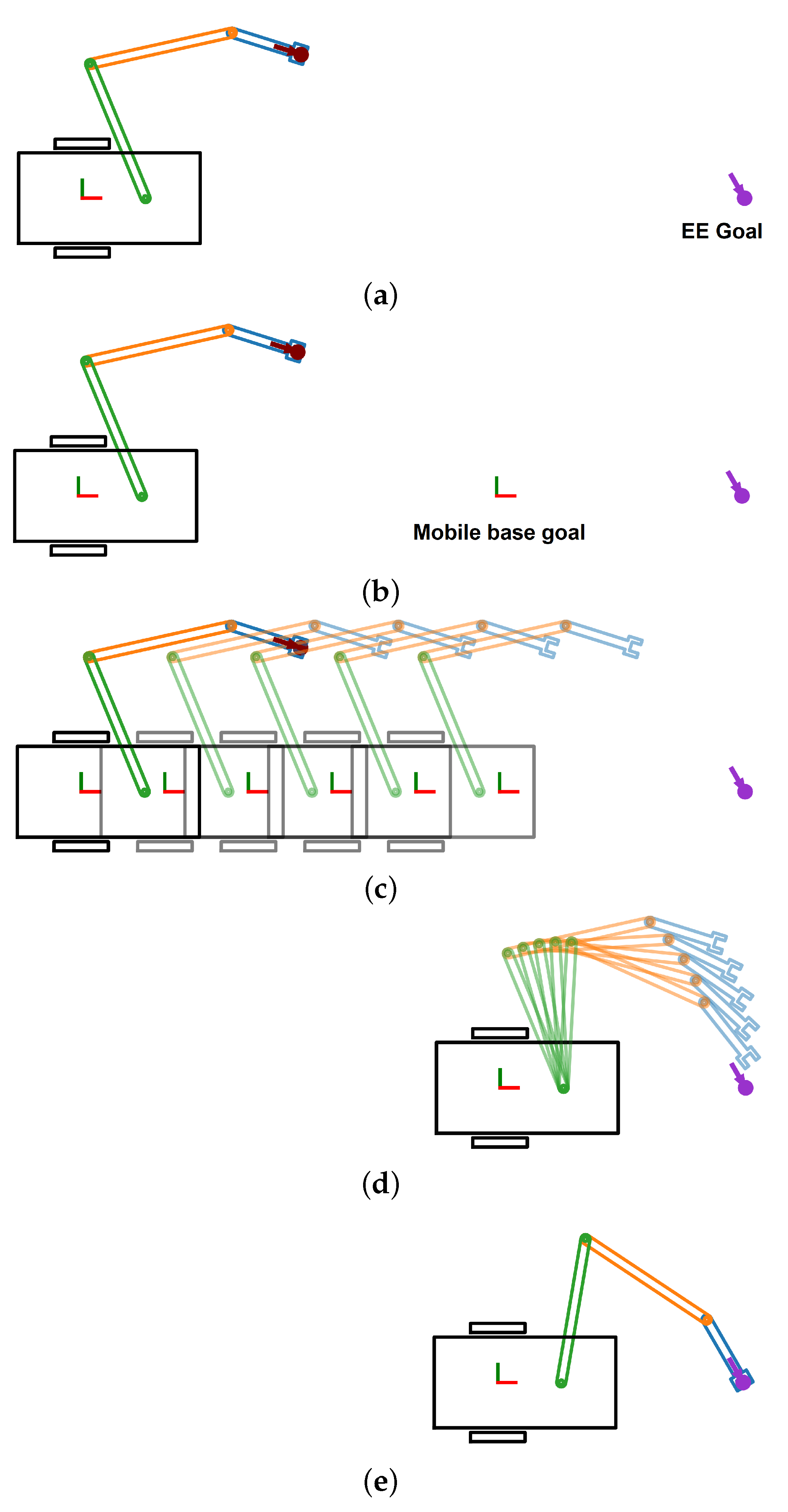
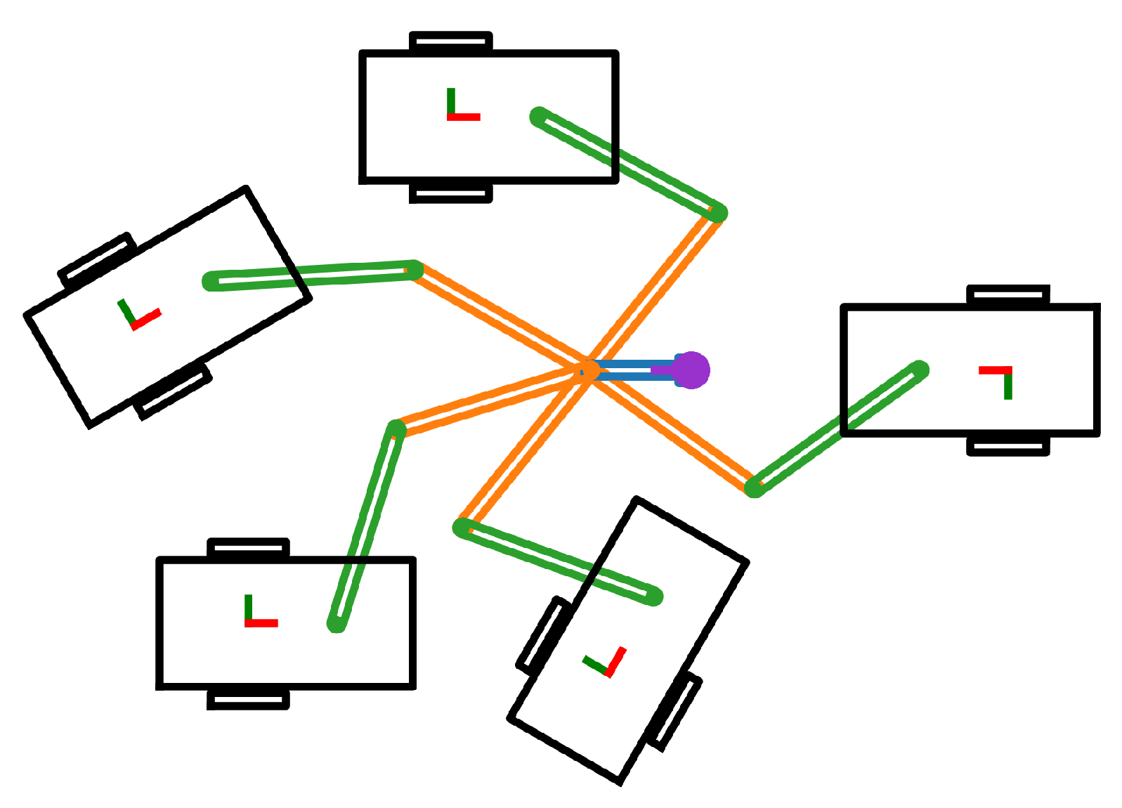
121] proposed a variant of RRT for following a given EE path. The main contribution was related to the sample generation algorithm specifically dealing with kinematic redundancies. The configuration space was divided into two partitions: base variables and redundant variables. The authors selected the configuration variables of the mobile base as redundant variables. For each point in the trajectory, redundant variables were sampled randomly and then the configuration of the manipulator was calculated using inverse kinematics. If the inverse kinematic solution was available, the combined configuration was used by the planner. The redundant variables were sampled from a coarse estimation (circle with radius equal to sum of link lengths) of the mobile base locations such that the end effector pose was reachable. If a biasing configuration parameter (e.g., the goal configuration) was given to the sample generation algorithm, the redundant variables were generated by first selecting a pseudovelocity which optimized some criteria (weighted Euclidean distance between configurations or Task compatibility of the manipulator) and then moving the system according to the selected pseudovelocity by using the system’s equation of motion.
Hierarchical and adaptive mobile manipulator planner (HAMP) [122] proposed by Pilania and Gupta was another method that planned with adaptive dimensionality. HAMP first planed the mobile base path using PRM considering a fixed manipulator configuration. Then, for each edge along the path (found using a variant of Dijkstra’s algorithm with Euclidean distance as the cost), collision between the manipulator and the environment was checked and if there was collision, the manipulator was moved to a new configuration by building a manipulator PRM such that collision was avoided along the mobile base edge. In [123], the authors further improved the algorithm to HAMP-U which considered the mobile base pose uncertainty during the planning process.
Optimized Hierarchical Mobile Manipulator Planner (OHMP) [124] was proposed by Li et al. to deal with the narrow passage exploration problem in PRM by using a hybrid sampling strategy (Hybrid Randomized Bridge Builder (HRBB) [125]. The authors defined a narrow passage as a space where the width was less than the diameter of the manipulator’s reachable workspace. First, a path was planned for the mobile base using PRM and at each mobile base node, if the manipulator was in collision, the manipulator was moved to a safe configuration. This was another planner with adaptive planning dimension where the planning dimension was increased only when required. However, various parameters were required to be tuned in order to achieve superior performance while collision checking for the manipulator was carried out using a 2D projection onto the floor. To get smooth trajectories for the manipulator, the authors used cubic polynomials.
Bidirectional Informed RRT* (BI2RRT*) was proposed in [113] (Extension of Informed RRT* [87]) which quickly generated an initial path and improved the path if more planning time was available. Once an initial path was found, informed sampling was carried out from two hyperellipsoids (One for revolute components of the mobile manipulator and one for prismatic components) which were centered around current nodes. To satisfy task constraints, a first-order retraction method [92] was used for sample projections.
In [126,127], the authors used CBiRRT2 [88] for motion planning. The tasks were categorized into two types: move the EE accurately to the goal, and exert a large force by EE. To move accurately to a goal pose, the manipulator motion needed to be given prominence and it was easier to exert forces using the mobile base. These two types of motions were prioritized by using proper weighing matrix in calculating the distance between two configurations.
Kang et al. [128] proposed a new sampling approach for LazyPRM* [129] to be used for motion planning of mobile manipulators. Their sampling method named Harmonious sampling was used for optimal motion planning which helped to efficiently explore the high-dimensional configuration space of both the mobile base and the robot manipulator. This sampling method adjusted the planning space dimension in such a way that in complex regions both the base and the manipulator were moved simultaneously while in other regions only the mobile base was moved. The authors defined two complex regions: near the end effector goal pose and near obstacles creating narrow passages. This was also another planner with adaptive dimensionality.
Time-optimal local planners for a differentially driven robot were introduced in [130]. In [131], the authors further introduced two concepts named detachability and time dominance which expanded the suggested local planners when planning for mobile manipulators. Detachability was related to the cost function where if satisfied, it allowed to join new local planners to the previously available ones. When planning for a mobile manipulators, this property allowed the use of local planners developed for mobile bases coupled with local planners for manipulators rather than developing new local planners for the whole system from scratch. The algorithms were tested on a mobile manipulator performing a task of moving between two configurations while maintaining an object within manipulator-mounted camera’s FoV.
Hybrid Sampling-based Bi-directional RRT (HS-Bi-RRT) [132] used a hybrid sampling strategy with BiRRT in configuration space for path planning (Alternate Task space and Configuration Space Exploration (ATACE)). The free space (the authors named this as focus region) for the mobile base was represented as a collection of overlapping disks and for the manipulator’s end effector, free space was represented using overlapping spheres. The trees were grown in the configuration space, but each node included information about the EE pose as well. The hybrid sampling was done on the configuration space (mobile base position inside a disk while mobile base orientation and manipulator configuration were random) or on the task space (Homogeneous matrix such the EE position was within a focus sphere). As the mobile base was non-holonomic, in finding the nearest neighbor, first, few neighbors were found considering only the mobile base position and then one was selected based on the closeness in manipulator’s configuration space.
RRT*-Constrained Riemannian Mapping Manipulability (RRT*-CRMM) was introduced in [133]. The samples were obtained from the point cloud which represented the object to be manipulated and the configuration was obtained using constrained Jacobian matrix. The cost between two configurations accounted for EE displacement, manipulability, and movement of the mobile base.
Lee et al. [134] used the Genetic algorithm in calculating commutation configurations (Intermediate configurations for several sequential EE poses) while the cost to be optimized was a weighted average between the cost of the current EE pose (Encode information about obstacle avoidance, joint limits, joint torque limits) and the cost of the path to the next EE. Once the commutation configurations were decided, the trajectory between two configurations was planned using Lagrangian formulation while the path cost included costs related to obstacle avoidance, joint torques and manipulability.
In [135], the authors addressed the problem of mobile base placement for several sequential EE poses. The optimum configurations for each EE pose were calculated using the Genetic Algorithm which minimized the number of mobile base movements and change in manipulator configuration subject to joint angle limits and collision avoidance. The path between these optimum configurations was planned using RRT-Connect algorithm.
Mobile manipulator path for a given EE trajectory was calculated using Full Space Parameterization (FSP) with Lagrangian optimization [136]. The inverse kinematics problem for each EE pose was solved using Lagrangian optimization where the non-holonomic constraint was linearized about the current operating point and was included in the optimization process.
The Augmented Lagrangian Method was used for optimization in [137] to calculate the mobile manipulator configurations for a given EE trajectory. The cost to be minimized was the Euclidean distance in configuration space (Mobile base movements were penalized more) while reaching the desired EE position and maintaining a desired manipulability. Furthermore, the authors suggested to have a upper bound on yaw angle of the mobile base to ensure acceptable path curvature.
Real-Time Adaptive Motion Planning (RAMP) [138] was similar to the Evolutionary algorithms in path planning with few with differences (used random selections and random modification operations, drastic changes rather than small changes (mutations), and less tuning parameters (just population size)). The planner modified the paths to account for the motion of the obstacles at each planning cycle. The path feasibility was checked considering execution time, energy consumption and manipulability index. Manipulator trajectory was represented using cubic splines while the mobile base trajectory was a linear trajectory with parabolic bends where both trajectories were loosely coupled by having few connected configurations (Knot points).
In [139], the authors collected path data from a demonstration by a human. Then, during the path planning process, each configuration in the path was modified to account for the mobile base pose error and the distance to obstacles to get a better path. The authors used their previous knowledge [140] to quantify the effect of base pose error on the EE pose error.
Welschehold et al. [141] also learned the motions by human demonstration. The task of moving through a doorway was executed using the paths generated by the learned model. The demonstrations were linked to the robot motions by formulating a graph and carrying out optimization to satisfy the robot’s kinematic constraints. One of the main benefit in this approach was that the demonstrations did not needed to be tailored to robot learning.
In [142], the authors proposed HRL4IN, a novel hierarchical RL architecture for interactive navigation tasks. The RL model was trained to efficiently use mobile base navigation, manipulator motion, and their combination in different phases of the task. The model was able to generate velocity commands to drive the robot towards the goal.
Raja et al. [143] used modified Kohonen Self-Organizing Map (KSOM) to calculate the mobile manipulator configurations for a given EE trajectory. A mapping between the task space and configuration space was learned while maximizing manipulability and minimizing the end effector error. More weightage was given to the mobile base movement in the cost function to restrict the heavier mobile base movement.
In [
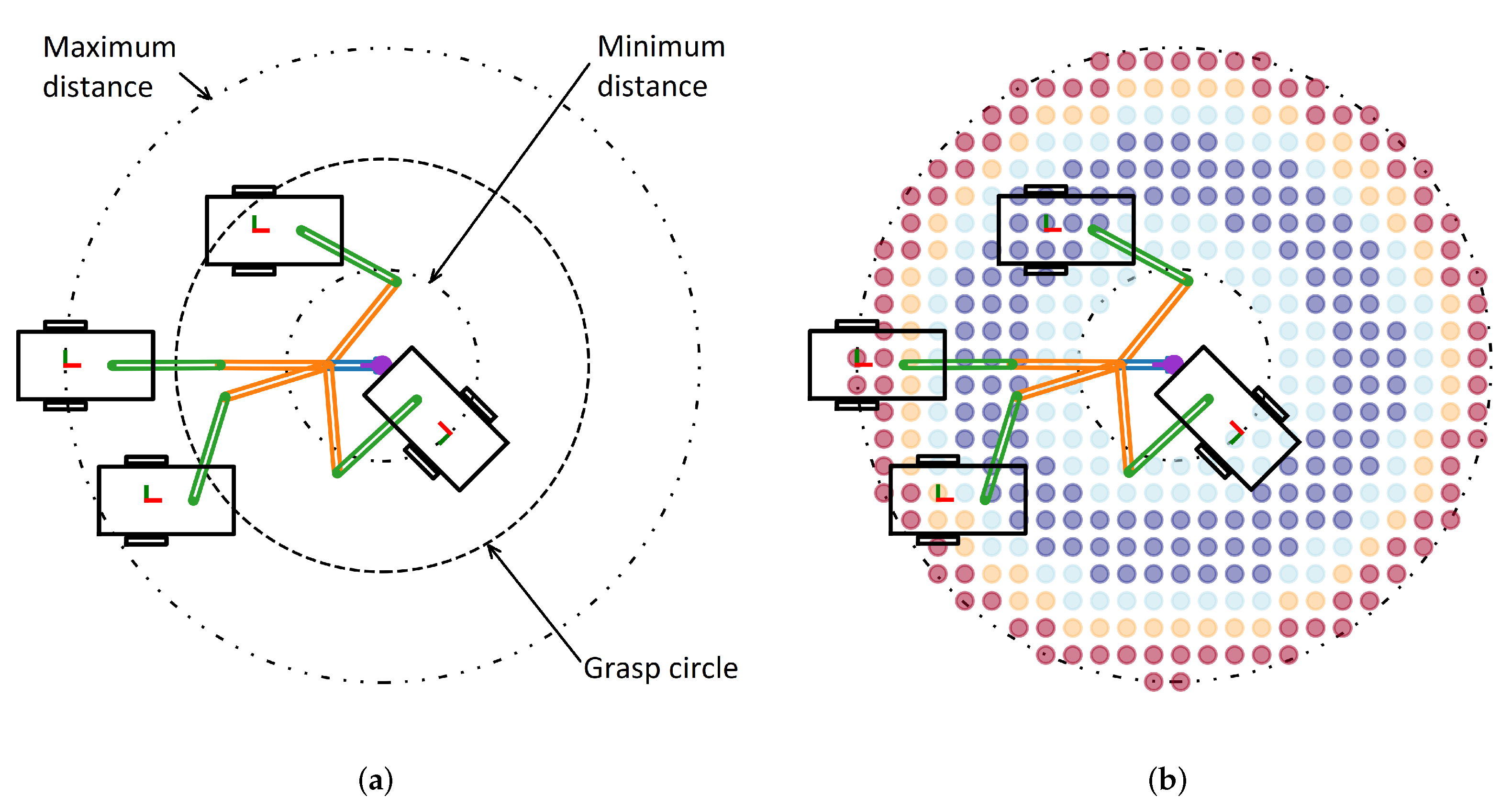
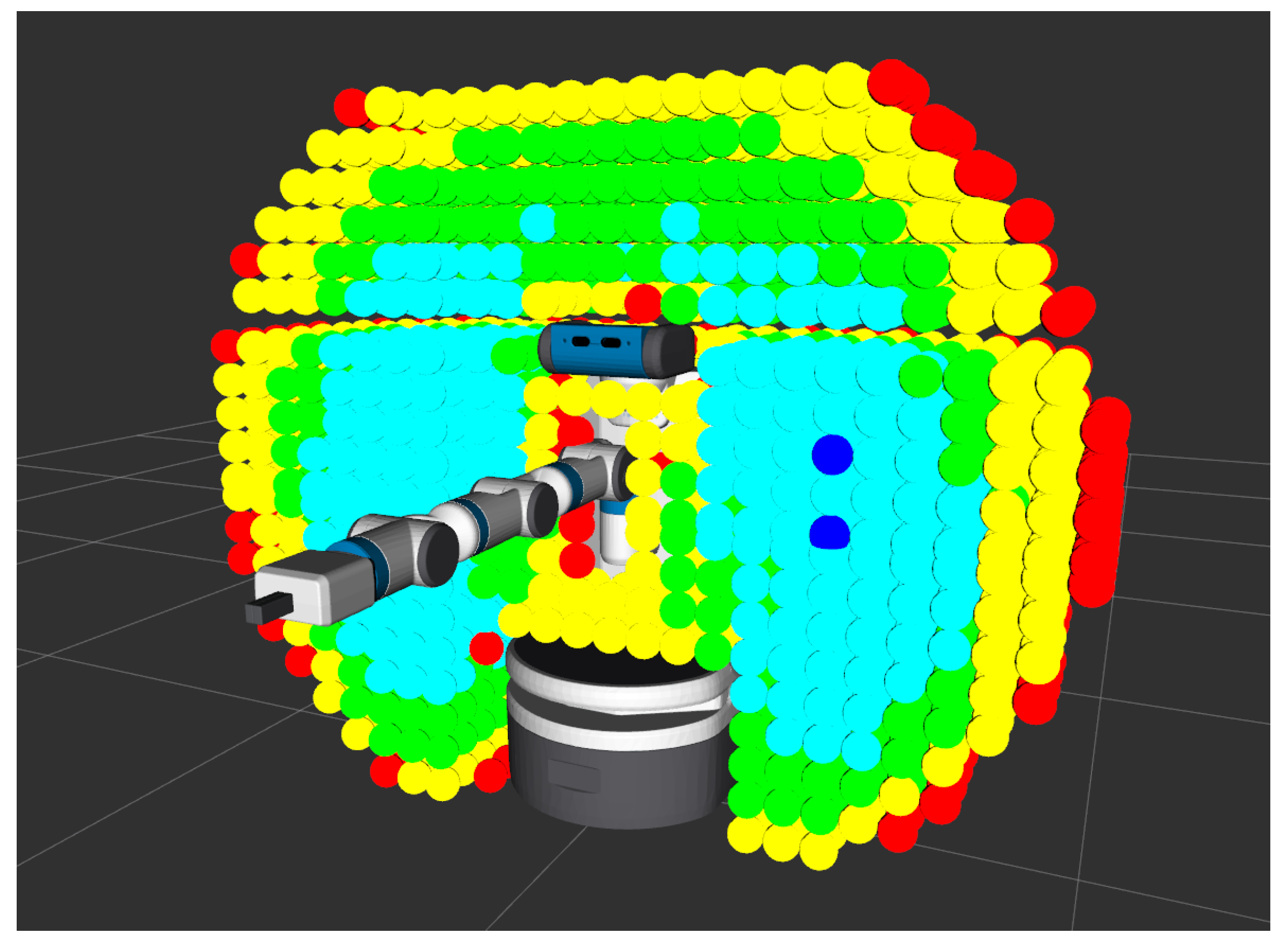
144], Zhang et al. proposed to use the Capability map and the Inverse Capability map for motion planning. The motion planning task was to define a path for a given end-effector trajectory such the manipulator maintains high manipulability by coordinating between the mobile base and the manipulator. First, for each of the discretized points in the end effector trajectory, a set of suitable mobile base configurations were calculated using the capability map of the manipulator. Then, an initial path for the mobile base through these point sets were calculated by starting from the initial pose and iteratively selecting the nearest pose from the next pose set. This initial path was then optimized to yield the shortest path by using hyper-ellipsoids where configurations were sampled from the hyperellipsoid and if the path through the new configuration was shorter, the path was updated. Once the base poses were finalized, the manipulator configurations were calculated using inverse kinematics. One of the main contributions in this work was on fast algorithm for generating a set of suitable mobile base poses for a given end effector pose. As the mobile base needed to be upright i.e., roll and pitch angles needed to be zero, the capability map was filtered to remove points that violated those conditions which significantly reduced the number of points in the capability map. Then, the feasible mobile base configurations were calculated and further filtered to remove points with low manipulability.
Welschehold et al. [145] used the obstacle avoidance principle introduced by [146] to calculate the mobile base poses such that the given EE poses were reachable. The suitable base pose bounds were modeled as ellipses where the inner bound was treated as an obstacle (to keep the mobile base away from that region) while the outer bound was treated as an inverse obstacle to keep the mobile base within the outer bounds. However, only the mobile base position was handled by the above method where the acceptable orientation ranges were obtained from a lookup table based on the EE pose and mobile base pose.
Summary of motion planning algorithms discussed in this section is included in Table 3 (properties of these planners are summarized in Appendix B.2).

4. Calculate Goal Configuration

In almost all the real-world applications, the goal state of the mobile manipulator is specified in the task space whether it is grasping a cup on a table or picking up a box from a shelf. The start configuration is usually available for the planner to use as the planner starts from the current state of the robot. If the planner is operating in the configuration space (e.g., using RRT algorithm in configuration space), the goal state also needs to be stated in the configuration space. Due to the usual kinematic redundancy of the mobile manipulator, transforming this task space goal state to a goal configuration using inverse kinematics will result in infinite solutions (Figure 2). However, all of these solutions would not be feasible due to the constraints applied on the problem. Therefore, deciding the goal configuration for a mobile manipulator is not a question with one definite answer. Summary of different techniques used for this calculation is included in Table 4.
As the manipulator has a limited reachable workspace, the minimum requirement for selecting the mobile base goal configuration is that the task space goal should be within the reachable workspace of the manipulator. In [36,121], the authors simply considered a circular region about the task space goal as the boundary to place the mobile base. The radius of the circle (the authors referred it to as Grasp circle) (Figure 3a) was selected as the average of maximum radius (Manipulator was fully extended, i.e., kinematic limit) and minimum radius (Limited by collision with the mobile base) of all possible grasp circles. Welschehold et al. [145] modeled the boundary of this region about the task space goal as a ellipsoid with a elliptical hole in the middle for PR2 robot. In [147], the manipulator’s reachable workspace boundary was calculated using joint sweeps and the mobile base configuration was selected such that the EE goal was within the reachable workspace boundary. Akli et al. [38] considered the base placement region as a square around the task space goal steaming from the joint limits and manipulator geometry. The Cartesian coordinates of the mobile base was randomly sampled from this squared region and the mobile base motion was planned which defined the final orientation of the non-holonomic base.
Merely considering a boundary for the mobile base placement does not guarantee that the EE goal is reachable due to the kinematics behavior of the manipulator. Even if the IK solution for the manipulator is available, it may be a singular configuration. Therefore, in [38], the ability of the manipulator to reach the task space goal was verified by ensuring that the manipulator’s inverse condition number [39] was greater than a threshold.
In [140,148], the mobile base location was selected from a 2D grid surrounding the task space goal based on some measure and inverse kinematics was used to calculate the manipulator configuration.
The reachability index distribution of a manipulator was calculated (Figure 4). Then, this was converted to the Inverse Reachability Map which was the collection of possible base configurations based on kinematic reachability of the manipulator [148] (Figure 3b) and was filtered using the task space goal and the fact that most mobile manipulators operated on a flat surface. This had more information relating to the possible mobile base configurations rather than just the boundary. The mobile base configuration was selected based on the reachability score which maximized the manipulator’s ability to reach the EE before fixing the manipulator configuration. Once the mobile base configuration was decided, the manipulator configuration was calculated using inverse kinematics algorithm.
Xu et al. [149,150] used the reachability database to find the joint configurations for a given EE pose rather than using an IK solver. Even though this method did not result in exact solutions, larger number of approximate configurations were obtained which increased the probability of finding a collision-free configuration. It was proven that this method was resolution complete. For each of the EE pose, the possible mobile base configurations were calculated and intersection was taken to arrive at the final mobile base pose distribution. The centers of these disjoint distributions were taken as the mobile base poses as those were considered to be robust against mobile base pose uncertainty.
In [151], the authors used the reachability map (Figure 4) to calculate the potential mobile base locations. For a EE pose, the mobile base locations were filtered based on collision using a physical engine. As the robot moves on a flat surface, the mobile base poses without upright orientations were also filtered and the feasibility of the available poses were further validated by calculating a mobile base path using A* algorithm. Then, the filtered poses were clustered into uniform cells. For each of the EE goal, the collection of mobile base poses were calculated and the suitable poses and the sequence was selected by formulating the problem as a Traveling Salesman Problem with Pickup and Delivery (TSPPD) problem.
In [152], the inverse reachability map was extended to a surface map which showed the reachability distribution about a flat polygon shape (like a desk). The mobile base poses were sampled from this distribution and verified for EE pose reachability before using for planning queries. This helped to improve the planning queries success rate. However, the surface map needed to be calculated offline and could only be used for that particular robot and polygon.
The authors of [153] first created a distribution of valid mobile base poses and selected the pose with the highest quality measure. Suitable area around the EE pose was sampled and for each of the mobile base sample, the manipulator joint configurations were calculated using IK and the extended manipulability measure (considering manipulability index, joint limits and self collision) was calculated. The mobile base pose with the highest extended manipulability measure was selected.
In all the above methods, the goal was to ensure that the EE pose was reachable by the manipulator. While the infinite solution space for inverse kinematics allows for optimization where it is possible to select one solution based on some cost criterion. Different researchers have used different cost criterion and optimization techniques to calculate the goal configuration [37,83,89,113,140,154,155,156,157]. In [154,155], the authors used the same cost criterion (they considered absolute joint torque values, joint torque distribution among joints, distance to obstacles, and a Jacobian-based manipulability measure (Equation (4)), while the authors of [154] used Lagrangian formulation with Newton and Tunneling-type algorithms for optimization whereas [155] used the Genetic Algorithm.
C o s t ( q ) = a t o r q u e _ n o r m τ q 2 + a t o r q u e _ d i s t r i b u t i o n m a x i | B i τ q i | + a m a n i p u l a b i l i t y 1 d e t ( J J T ) + a o b s t a c l e λ x x o b s 2
τ q = [ τ b , α τ a ] with scalar parameter α decides the relative importance between mobile base and manipulator torques. B i is a weighing factor representing the inverse of the individual joint torque limits. J is the Jacobian matrix of the manipulator. λ is a scalar parameter with x and x o b s is a Cartesian point on the mobile manipulator and on an obstacle, respectively. a t o r q u e _ n o r m , a t o r q u e _ d i s t r i b u t i o n , a m a n i p u l a b i l i t y , and a o b s t a c l e are scalar parameters deciding the relative importance between each cost item. For Berenso et al., in [83], the cost included grasp quality, manipulability, and distance to obstacles which was optimized using co-evolutionary algorithm. However, this required the grasps to be parameterized in order to be used in optimization.
One of the practical limitations of mobile base motions is the uncertainty in localization (i.e., calculating the exact mobile base pose). Yamazaki et al. [140] selected the mobile base location such that the expected manipulator recovery motion was minimum (which was required to correct the task space error created by the uncertainty of the non-holonomic mobile base placement). The recovery motion was handled by the manipulator as pose correction of non-holonomic mobile base was difficult. In [140,158], the authors improved their algorithm to consider multiple task space goals (same position but different orientations to grasp an object) and select the best goal configuration. However, this method was only applied on planar mobile manipulators and as a result, no explicit collision detection was carried out. Further, the method used to find the best mobile base location (similar to Gradient descent algorithm on a grid) suffered from a local minima problem, to which the authors suggested using multiple initial seeds.
Table 4. Summary of goal configuration calculation methods.
ReferenceCriteriaCalculation method
[36,121]EE pose reachabilityRandom sample inside circle & IK
[145]EE pose reachabilityRandom sample inside ellipse & IK
[147]EE pose reachabilityEE inside the boundary
[38]EE pose reachabilityRandom sample inside square & IK
[148]Reachability scoreGrid search
[154]Absolute joint torque values, Joint torque distribution among joints, Distance to obstacles and Manipulability measureLagrangian formulation
[155]Absolute joint torque values, Joint torque distribution among joints, Distance to obstacles and Manipulability measureGenetic Algorithm
[83]Grasp quality, manipulability and distance to obstaclesCo-evolutionary Algorithm
[140]Expected recovery joint motionGrid search
[149,150]EE pose reachabilityCenter of distribution
[151]Reachability scoreTSPPD problem solving
[152]Reachability scoreRandom sample within and verify
[153]Extended manipulability measureGrid search
[156]Euclidean distance from the start configurationDeoxyribonucleic acid Algorithm
[113]Same connected space as the start configurationDamped least-square IK algorithm
[157]Euclidean distance from the start configuration and EE errorParticle swarm optimization (PSO)
[99]EE error, manipulability, joint displacement and EE displacement w.r.t. mobile baseImproved MaxiMin NSGA-II Algorithm
[109]EE error, joint displacement, Joint limit violation penaltyMetaheuristic algorithms
[89]Motion plan costSequential planning
[37]Mobile base velocityLagrangian formulation
Huang et al. [156] calculated the goal configuration by minimized the Euclidean distance from the start configuration using Deoxyribonucleic acid algorithm (DNA), while higher weights were given for mobile base movements as those required more time to execute. Burget et al. [113] also tried make the goal configuration closer to start configuration while ensuring that both configurations does not lie in disjoint regions of the configuration space. To achieve this, the damped least-square inverse kinematics algorithm [159] was used with seeds generated by Gaussian sampling around the start configuration. Ram et al. [157] used Particle swarm optimization (PSO) to calculate the goal configuration with a fitness function accounting for the total joint movement from the start configuration and the end effector error.
In [99], the authors used the improved MaxiMin NSGA-II Algorithm to calculate the goal configuration while optimizing the EE position and orientation error, manipulability, joint displacement relative to joint limits, and EE displacement with respect to the mobile base.
In [109], different metaheuristic algorithms (CS, DE, HBBO, PSO, and TLBO) were used to calculate the mobile manipulator configurations. The cost function to be optimized considered the EE error, joint movement, and a penalty term for violating the joint limits.
The motivation in [113,156] was to make the motion plan cost (estimated as the distance between the start and goal configurations) lower by reducing the joint movements. However, the actual motion plan cost was not explicitly calculated. In [89], the authors considered multiple goal configurations arranged in the ascending order of Manhattan distance [160] from the start configuration and sequentially calculated the motion plans for each goal configuration in the list. Then, the best goal configuration was selected if the actual cost of the motion plan was less than the Manhattan distance cost of the next goal configuration in the list. This method ensured that the total cost of the motion plan was optimized rather than the goal configuration cost. However, this came with a significant increase in computational load due to the motion plan calculation for each goal configuration.
Foulon et al. [37] suggested that, depending on the mobile manipulator structure, the manipulability index can be maximized for an infinite set of configurations. Therefore, the author proposed to find the mobile base location by minimizing the mobile base velocity along the path. Optimization was done using Lagrangian multipliers subject to EE goal reachability (circle centered on the EE position). The motivation for this suggestion was that the manipulator was easier to move compared with the non-holonomic mobile base. The authors also proposed another method where the position of the mobile base was first calculated minimizing the square of y-axis coordinate and then the mobile base orientation was calculated by minimizing the velocity along the path.

5. Discussion

In planning motions for mobile manipulators, separate planning for the two subsystems was the simpler approach. This allowed to use the available planning algorithms proven on each subsystem but the method did not utilize the mobile manipulator to the fullest. In planning to follow a EE trajectory, either the mobile base or manipulator path was planned first and the other’s path was derived using kinematic relations. Optimization algorithms coupled with kinematics relationships were used for this but these methods were prone to local minima, required computationally expensive cost function evaluations at each iteration and rarely considered system dynamics during planning. Tip-over stability was considered in [45,46,47] but this was also regarding static tip-over stability while the planned paths were modified to a safety margin over the tip-over condition.
When the mobile manipulator was considered as a single high DOF system, the system’s kinematic redundancy was utilized to plan complex motions. Calculating a free space representation and finding a path was a computationally expensive approach which required the representation to be updated if there were dynamic obstacles. Building a graph in the free space was less computationally expensive and several researchers utilized this idea while using prevailing graph search algorithms to find feasible paths. When optimization algorithms were used to plan trajectories, it was possible to evaluate complex cost function which was an advantage. However, these algorithms usually required high memory usage for path storage while evaluating complex cost functions was computationally expensive. Further, the inherent mathematical complexity of these optimization algorithms adversely impacted their implementation on real world applications. General sampling based planners were able to generate a path in a reasonable time but these path usually were of low quality in terms of smoothness and path cost. Low-cost paths were obtained using asymptotically optimal sampling based planers while the smoothness problem was alleviated using post processing techniques. To guide the tree in the high-dimensional space, some researchers proposed to use the task space information but calculating this information was computationally expensive. To satisfy task space constraints, rather than doing the computationally expensive sample projections, task space points were sampled and IK was used to calculate configuration space samples. Even though this method was further extended to consider task constraints within a range, it was not able to constrain EE orientations. Some optimization algorithms under this category were able to account for system dynamics and prevent tip-over and joint torque limit violations. However, these algorithms required high computational power while being prone to local minima. Machine learning techniques were used to supplement the motion planning algorithms which can be explored further.
To utilize the mobile manipulator to the fullest, the different capabilities of the mobile base and the manipulator were identified and exploited by several researchers. Building a motion graph in the free space and searching for a path could result in optimal plans but path quality highly depended on the number of motion primitives and the resolution used. Deciding the suitable motion primitives such that the system was stable required complex system analysis. In most instances, it was sufficient to either move the mobile base or the manipulator. This fact was incorporated into sampling based planners where the planners planned with adaptive dimensionality. Researchers used different techniques to identify when to change the planning dimension. Manipulator collision, narrow passages, and proximity to goal state were some of the cases where planning in a high dimension was required. While this approach helped to efficiently explore the planning space, determining when to change the planning space dimension was a challenge. Some optimization-based planners penalized mobile base movements more, as it was difficult to move the mobile base compared with manipulator motion. Several researchers used the manipulator’s ability to reach an EE pose to guide the mobile base motion. This method required a map of manipulator’s capabilities to be calculated. Even though this map generation required computation resources, this was outweighted by the reduced planning time and quality increment of the generated paths.
In transforming a task space goal to a configuration space goal, the mobile base configuration was chosen to ensure EE pose was reachable by the manipulator which was the minimum requirement. This was simply satisfied by selecting the mobile base configuration within a boundary. Even though this approach was simpler, this does not guarantee that the manipulator was able to comfortably reach the EE pose. Due to the kinematic structure, there might be singular configurations. Using reachability score greatly reduced the probability of having a singular configuration but this came with an increase in computational cost. Different cost functions, while satisfying reachability, were optimized using different techniques to calculate the goal configuration. These optimization algorithms were prone to local minima or had several parameters that needed to be tuned if good performance was needed. Some algorithms needed parameterized variables for optimization which could be difficult to formulate. Some researchers tried to account for practical limitations such as mobile base localization error in calculating the goal configuration but the proposed method was prone to local minima and was only implemented on a 2D planar robot. Considering only the conditions at the goal configuration may not be the optimal solution when considering the whole motion. Therefore, an argument was made to select the goal configuration such that the motion plan cost was minimum. In the simplest form, the goal configuration was selected to be closer to the start configuration but this was a very crude approximation of motion plan cost. Calculating motion plans for different goal configurations and selecting the best one was was conceptually superior, it came with a significant increase in computational cost.
In optimization problems, it was difficult for model-based optimization algorithms to calculate a solution due to the complex constraints of the mobile manipulator system. This required significant computational resources. Therefore, learning-based algorithms such as Genetic Algorithm and Evolutionary Algorithm were popular choices for optimization problems. The characteristics of the mobile manipulator made the planning space topology complex. Therefore, model-based algorithms were at a disadvantage. Even with high computational capabilities, it may not be possible to calculate an exact representation of the planning space. Even if it was possible, a change in the environment made the representation obsolete. This made it difficult for sampling-based algorithms to find a solution quickly by guiding the space exploration. As a remedy, learning-based algorithms were used to generate an approximate representation of the free space and guide the exploration. These learning-based methods, specially machine learning techniques increased in popularity in recent years and have helped to improve the performance of conventional algorithms by generating relevant heuristics.

6. Conclusions

Unique kinematic and dynamic behaviors of mobile manipulators pose unique challenges for motion planning algorithms. Even though separately planning for a mobile base and an manipulator is convenient, sub-optimal plans will be generated. When using sampling-based, optimization-based, grid-based, or other planning algorithms, the mobile manipulator can simply be considered as a high DOF system. This allows for optimal plans to be generated based on the used criteria, but the computational cost may be higher. To alleviate this problem, knowledge about the manipulator’s capabilities and system’s behavior can be utilized during the planning process.
Coordination between the mobile base and manipulator during the planning phase was not fully explored in the literature along with utilizing the mobile manipulator’s unique capabilities. This is a significant research opportunity, specially calculating the mobile manipulator’s capabilities using machine learning techniques and using the derived knowledge in planning algorithms. This will help to coordinate motion between the mobile base and the manipulator. Most of the planning algorithms were focused on geometric path planning rather than motion planning, while system dynamics was not extensively used during the motion planning phase. A geometric plan may not be executable due to the dynamic limitations of the system which promotes studies on kinodynamic planning algorithms. In practical applications, it is common for the mobile base and the manipulator to have two separate controllers with different control loop rates. For superior performance, these two controllers need to be properly coordinated. This creates the interesting research question pertaining to the controller coordination as well. The planned paths are given to the controller to be executed. Taking this controller coordination into consideration during the motion planning stage is an interesting research direction. Even though few works considered the uncertainty of operating in the real world, this is a open research field which helps to produce robust planning algorithms. With the development of human–robot collaborations, planning with dynamic environments and human-aware planning are also few research areas with significant potential.

Author Contributions

Conceptualization, T.S. and M.H.A.J.; methodology, T.S.; software, T.S.; validation, T.S. and M.H.A.J.; formal analysis, T.S.; investigation, T.S.; resources, T.S.; data curation, T.S.; writing—original draft preparation, T.S.; writing—review and editing, M.H.A.J.; visualization, T.S.; supervision, M.H.A.J.; project administration, M.H.A.J.; funding acquisition, M.H.A.J. All authors have read and agreed to the published version of the manuscript.

Funding

This research was funded by National University of Singapore—NUS Research Scholarship grant number GOSU00000042 PVO ARS-FOE 101 IS.

Institutional Review Board Statement

Not applicable.

Informed Consent Statement

Not applicable.

Data Availability Statement

Not applicable.

Conflicts of Interest

The authors declare no conflict of interest.

Abbreviations

The following abbreviations are used in this manuscript:
MMMobile Manipulator
DOFDegrees of Freedom
CSConfiguration Space
TSTask Space
FKForward Kinematics
IKInverse Kinematics
RRTRapidly-exploring Random Trees
PRMProbabilistic Road Maps
ESTExpansive space trees
EEEnd Effector

Appendix A

Table A1. Source codes and additional resources.
PublicationReferenceLink
Prehensile Manipulation Planning: Modeling, Algorithms and Implementation[119]Code
Receding Horizon Task and Motion Planning in Changing Environments[30]Code
Flexibly configuring task and motion planning problems for mobile manipulators[31]Code
HRL4IN: Hierarchical Reinforcement Learning for Interactive Navigation with Mobile Manipulators[142]Code
Reuleaux: Robot Base Placement by Reachability Analysis[148]Code
Motion planning with sequential convex optimization and convex collision checking[68]Code
Semi-Autonomous Behaviour Tree-Based Framework for Sorting Electric Vehicle Batteries Components[33]Code
Service robot system with an informationally structured environment[161]Code
Real-Time Adaptive Motion Planning (RAMP) of Mobile Manipulators in Dynamic Environments With Unforeseen Changes[138]Code*
Mobile Manipulation Tutorial[12]Code
Accelerating Bi-Directional Sampling-Based Search for Motion Planning of Non-Holonomic Mobile Manipulators[132]Material
A hierarchical and adaptive mobile manipulator planner[122]Material
A novel coordinated motion planner based on capability map for autonomous mobile manipulator[144]Material
Manipulation Planning and Control for Shelf Replenishment[110]Material
Planning in Time-Configuration Space for Efficient Pick-and-Place in Non-Static Environments with Temporal Constraints[100]Material
Real-Time Adaptive Motion Planning (RAMP) of Mobile Manipulators in Dynamic Environments With Unforeseen Changes[138]Material
* Not implemented by the authors.

Appendix B

Appendix B.1

Table A2. Properties of general high DOF planners.
ReferenceCompletenessOptimalityOffline vs. OnlineNon-Holonomic CompatibilityTask Constraint CompatibilityEnvironment
[64,65]CompleteYesOnlineNoYesDynamic
[66]CompleteBounded suboptimalityOfflineNoNoStatic
[102] Converges to OptimalOfflineYesNoStatic
[69] Converges to OptimalOfflineNoNoStatic
[72] Converges to OptimalOfflineNoYesStatic
[73] Converges to OptimalOfflineNoYesStatic
[108] Converges to OptimalOnlineNoYesDynamic
[109] Converges to OptimalOfflineNoYesStatic
[74,75] Converges to OptimalOnlineNoNoStatic
[70] Converges to OptimalOfflineNoYesStatic
[68,71] Converges to OptimalOfflineNoYesStatic
[76,77] Converges to OptimalOfflineYesNoStatic
[101] Converges to OptimalOfflineYesNoStatic
[104] Converges to OptimalOfflineNoYesStatic
[105] Converges to OptimalOfflineNoNoStatic
[107] NoOnlineYesYesStatic
[110] NoOfflineNoYesStatic
[112] NoOfflineNoNoStatic
[63]Not completeNoOnlineNoNoDynamic
[113]Probabilistic CompleteNoOfflineNoNoStatic
[86] *, [113]Probabilistic CompleteConverges to OptimalOfflineNoNoStatic
[88]Probabilistic CompleteNoOfflineNoYesStatic
[93]Probabilistic CompleteNoOfflineYesYesStatic
[81] *Probabilistic CompleteNoOfflineNoNoStatic
[98]Probabilistic CompleteNoOfflineYesNoStatic
[113]Probabilistic CompleteNoOfflineNoNoStatic
[87] *, [113]Probabilistic CompleteConverges to OptimalOfflineNoNoStatic
[67] *, [68]Probabilistic CompleteNoOfflineYesNoStatic
[79,80]Probabilistic CompleteNoOfflineNoNoStatic
[78] *, [113]Probabilistic CompleteNoOfflineNoNoStatic
[89]Probabilistic CompleteNoOfflineNoNoStatic
[90]Probabilistic CompleteNoOfflineNoYesStatic
[85] *, [113]Probabilistic CompleteConverges to OptimalOfflineNoNoStatic
[82] *, [68,83,113]Probabilistic CompleteNoOfflineNoNoStatic
[78] *, [84]Probabilistic CompleteNoOfflineNoNoStatic
[84]Probabilistic CompleteNoOfflineNoNoStatic
[97]Probabilistic CompleteNoOnlineYesYesStatic
[99]Probabilistic CompleteNoOfflineNoNoStatic
[91]Probabilistic CompleteNoOfflineNoNoStatic
[95]Probabilistic CompleteNoOfflineNoYesStatic
[93,94]Probabilistic CompleteNoOfflineYesYesDynamic
[100]Probabilistic CompleteNoOfflineNoNoDynamic
[96]Not completeNoOnlineNoYesStatic
* Algorithm’s original publication but no implementation on a mobile manipulator.

Appendix B.2

Table A3. Properties of planners with collaboration between mobile base and manipulator.
ReferenceCompletenessOptimalityOffline vs. OnlineNon-Holonomic CompatibilityTask Constraint CompatibilityEnvironment
[116] NoOfflineYesNoStatic
[118] NoOfflineYesNoStatic
[145] NoOnlineNoNoStatic
[138]Not completeConverges to OptimalOnlineYesYesDynamic
[134] Converges to OptimalOfflineNoYesStatic
[115] Converges to OptimalOfflineYesNoStatic
[136] Converges to OptimalOfflineYesYesStatic
[137] Converges to OptimalOfflineYesYesStatic
[135] Converges to OptimalOfflineNoYesStatic
[114] NoOfflineYesNoStatic
[139] NoOfflineYesNoStatic
[141] NoOfflineNoNoStatic
[142] NoOfflineNoNoStatic
[144]Not specifiedNoOfflineNoYesStatic
[143] NoOfflineYesNoStatic
[119]Probabilistic CompleteNoOfflineNoYesStatic
[113]Probabilistic CompleteYesOfflineNoYesStatic
[126,127]Probabilistic CompleteNoOfflineNoYesStatic
[123]Probabilistic CompleteNoOfflineNoNoStatic
[122]Probabilistic CompleteNoOfflineNoNoStatic
[132]Probabilistic CompleteNoOfflineYesNoStatic
[133]Probabilistic CompleteNoOfflineYesNoStatic
[128]Probabilistic CompleteConverges to OptimalOfflineNoNoStatic
[124]Probabilistic CompleteNoOfflineNoNoStatic
[121]Probabilistic CompleteNoOfflineYesYesStatic
[131]Probabilistic CompleteYesOfflineYesNoStatic

References

  1. Malone, B. George Devol: A Life Devoted to Invention, and Robots—IEEE Spectrum; IEEE: Piscataway, NJ, USA, 2011. [Google Scholar]
  2. Ullrich, G. (Ed.) The History of Automated Guided Vehicle Systems. In Automated Guided Vehicle Systems: A Primer with Practical Applications; Springer: Berlin/Heidelberg, Germany, 2015; pp. 1–14. [Google Scholar] [CrossRef]
  3. Available online: https://www.kuka.com/en-sg/products/robotics-systems/industrial-robots/kr-1000-titan (accessed on 14 October 2021).
  4. Outón, J.L.; Villaverde, I.; Herrero, H.; Esnaola, U.; Sierra, B. Innovative Mobile Manipulator Solution for Modern Flexible Manufacturing Processes. Sensors 2019, 19, 5414. [Google Scholar] [CrossRef] [PubMed] [Green Version]
  5. King, C.H.; Chen, T.L.; Fan, Z.; Glass, J.D.; Kemp, C.C. Dusty: An assistive mobile manipulator that retrieves dropped objects for people with motor impairments. Disabil. Rehabil. Assist. Technol. 2012, 7, 168–179. [Google Scholar] [CrossRef] [PubMed] [Green Version]
  6. Caselli, S.; Fantini, E.; Monica, F.; Occhi, P.; Reggiani, M. Toward a Mobile Manipulator Service Robot for Human Assistance. In Proceedings of the 1st Robocare Workshop, ISTC-CNR, Roma, Italy, 30 October 2003. [Google Scholar]
  7. Seo, K.H.; Lee, J.J. The Development of Two Mobile Gait Rehabilitation Systems. IEEE Trans. Neural Syst. Rehabil. Eng. 2009, 17, 156–166. [Google Scholar] [CrossRef] [PubMed]
  8. Li, Z.; Moran, P.; Dong, Q.; Shaw, R.J.; Hauser, K. Development of a tele-nursing mobile manipulator for remote care-giving in quarantine areas. In Proceedings of the 2017 IEEE International Conference on Robotics and Automation (ICRA), Singapore, 29 May–3 June 2017; pp. 3581–3586. [Google Scholar] [CrossRef]
  9. Kang, S.; Cho, C.; Lee, J.; Ryu, D.; Park, C.; Shin, K.C.; Kim, M. ROBHAZ-DT2: Design and integration of passive double tracked mobile manipulator system for explosive ordnance disposal. In Proceedings of the 2003 IEEE/RSJ International Conference on Intelligent Robots and Systems (IROS 2003) (Cat. No.03CH37453), Las Vegas, NA, USA, 27–31 October 2003; Volume 3, pp. 2624–2629. [Google Scholar] [CrossRef]
  10. Zereik, E.; Sorbara, A.; Casalino, G.; Didot, F. Autonomous dual-arm mobile manipulator crew assistant for surface operations: Force/vision-guided grasping. In Proceedings of the 2009 4th International Conference on Recent Advances in Space Technologies, Istanbul, Turkey, 11–13 June 2009; pp. 710–715. [Google Scholar] [CrossRef]
  11. Sereinig, M.; Werth, W.; Faller, L.M. A review of the challenges in mobile manipulation: Systems design and RoboCup challenges. E I Elektrotech. Inform. 2020, 137, 297–308. [Google Scholar] [CrossRef]
  12. Hou, J.; Zhang, Y.; Rosendo, A.; Schwertfeger, S. Mobile Manipulation Tutorial. Available online: https://robotics.shanghaitech.edu.cn/static/robotics2020/MoManTu_Intro.pdf (accessed on 14 January 2022).
  13. Youakim, D.; Ridao, P. Motion planning survey for autonomous mobile manipulators underwater manipulator case study. Robot. Auton. Syst. 2018, 107, 20–44. [Google Scholar] [CrossRef]
  14. Tudico, A.; Lau, N.; Pedrosa, E.; Amaral, F.; Mazzotti, C.; Carricato, M. Improving and Benchmarking Motion Planning for a Mobile Manipulator Operating in Unstructured Environments. In Progress in Artificial Intelligence; Lecture Notes in Computer Science; Oliveira, E., Gama, J., Vale, Z., Lopes Cardoso, H., Eds.; Springer International Publishing: Cham, Switzerland, 2017; pp. 498–509. [Google Scholar] [CrossRef]
  15. Ioan, A. Sucan and Sachin Chitta, MoveIt. Available online: moveit.ros.org. (accessed on 2 September 2021).
  16. Hu, F.; Bao, Y. Progress and Challenges of Hand-eye-foot Coordination for Mobile Manipulator. In Proceedings of the 2019 WRC Symposium on Advanced Robotics and Automation (WRC SARA), Beijing, China, 21–22 August 2019; pp. 360–366. [Google Scholar] [CrossRef]
  17. Arnold, V.I. (Ed.) Rigid bodies. In Mathematical Methods of Classical Mechanics; Graduate Texts in Mathematics; Springer: New York, NY, USA, 1978; pp. 123–159. [Google Scholar] [CrossRef]
  18. Latombe, J.C. (Ed.) Introduction and Overview. In Robot Motion Planning; The Springer International Series in Engineering and Computer Science; Springer: Boston, MA, USA, 1991; pp. 1–57. [Google Scholar] [CrossRef]
  19. Neimark, J.I.; Fufaev, N.A. Dynamics of Nonholonomic Systems; American Mathematical Society: Providence, RI, USA, 2004. [Google Scholar]
  20. Tzafestas, S.G. Mobile Robot Path, Motion, and Task Planning. In Introduction to Mobile Robot Control; Elsevier: Amsterdam, The Netherlands, 2014; pp. 429–478. [Google Scholar] [CrossRef]
  21. Yu, W. (Ed.) Chapter 1—Preliminaries. In PID Control with Intelligent Compensation for Exoskeleton Robots; Academic Press: Cambridge, MA, USA, 2018; pp. 1–12. [Google Scholar] [CrossRef]
  22. Foulon, G.; Fourquet, J.Y.; Renaud, M. Coordinating mobility and manipulation using nonholonomic mobile manipulators. Control Eng. Pract. 1999, 7, 391–399. [Google Scholar] [CrossRef]
  23. LaValle, S.M. Planning Algorithms; Cambridge University Press: Cambridge, UK, 2006. [Google Scholar]
  24. Thrun, S.; Burgard, W.; Fox, D. Probabilistic Robotics; Intelligent Robotics and Autonomous Agents Series; MIT Press: Cambridge, MA, USA, 2005. [Google Scholar]
  25. Zhang, H.Y.; Lin, W.M.; Chen, A.X. Path Planning for the Mobile Robot: A Review. Symmetry 2018, 10, 450. [Google Scholar] [CrossRef] [Green Version]
  26. Sánchez-Ibáñez, J.R.; Pérez-del Pulgar, C.J.; García-Cerezo, A. Path Planning for Autonomous Mobile Robots: A Review. Sensors 2021, 21, 7898. [Google Scholar] [CrossRef]
  27. Zafar, M.N.; Mohanta, J.C. Methodology for Path Planning and Optimization of Mobile Robots: A Review. Procedia Comput. Sci. 2018, 133, 141–152. [Google Scholar] [CrossRef]
  28. Gul, F.; Mir, I.; Abualigah, L.; Sumari, P.; Forestiero, A. A Consolidated Review of Path Planning and Optimization Techniques: Technical Perspectives and Future Directions. Electronics 2021, 10, 2250. [Google Scholar] [CrossRef]
  29. Ata, A.A. Optimal trajectory planning of manipulators: A review. J. Eng. Sci. Technol. 2007, 2, 23. [Google Scholar]
  30. Castaman, N.; Pagello, E.; Menegatti, E.; Pretto, A. Receding Horizon Task and Motion Planning in Changing Environments. Robot. Auton. Syst. 2021, 145, 103863. [Google Scholar] [CrossRef]
  31. Saoji, S.; Rosell, J. Flexibly configuring task and motion planning problems for mobile manipulators. In Proceedings of the 2020 25th IEEE International Conference on Emerging Technologies and Factory Automation (ETFA), Vienna, Austria, 8–11 September 2020; Volume 1, pp. 1285–1288. [Google Scholar] [CrossRef]
  32. You, Y.; Fan, Z.; Chen, W.; Zhu, G.; Qiu, B.; Xin, J.; Chen, J.; Deng, F.; Hou, Y.; Liang, W.; et al. Design and Implementation of Mobile Manipulator System. In Proceedings of the 2019 IEEE 9th Annual International Conference on CYBER Technology in Automation, Control, and Intelligent Systems (CYBER), Suzhou, China, 29 July–2 August 2019; pp. 113–118. [Google Scholar]
  33. Rastegarpanah, A.; Gonzalez, H.C.; Stolkin, R. Semi-Autonomous Behaviour Tree-Based Framework for Sorting Electric Vehicle Batteries Components. Robotics 2021, 10, 82. [Google Scholar] [CrossRef]
  34. Engemann, H.; Du, S.; Kallweit, S.; Cönen, P.; Dawar, H. OMNIVIL—An Autonomous Mobile Manipulator for Flexible Production. Sensors 2020, 20, 7249. [Google Scholar] [CrossRef]
  35. Hu, D.; Zhong, H.; Li, S.; Tan, J.; He, Q. Segmenting areas of potential contamination for adaptive robotic disinfection in built environments. Build. Environ. 2020, 184, 107226. [Google Scholar] [CrossRef]
  36. Jiao, J.; Cao, Z.; Zhao, P.; Liu, X.; Tan, M. Bezier curve based path planning for a mobile manipulator in unknown environments. In Proceedings of the 2013 IEEE International Conference on Robotics and Biomimetics (ROBIO), Shenzhen, China, 12–14 December 2013; pp. 1864–1868. [Google Scholar] [CrossRef]
  37. Foulon, G.; Fourquet, J.; Renaud, M. Planning point to point paths for nonholonomic mobile manipulators. In Proceedings of the 1998 IEEE/RSJ International Conference on Intelligent Robots and Systems. Innovations in Theory, Practice and Applications (Cat. No. 98CH36190), Victoria, BC, Canada, 17 October 1998; Volume 1, pp. 374–379. [Google Scholar] [CrossRef]
  38. Akli, I.; Bouzouia, B.; Achour, N. Motion analysis of a mobile manipulator executing pick-up tasks. Comput. Electr. Eng. 2015, 43, 257–269. [Google Scholar] [CrossRef]
  39. Togai, M. An application of the singular value decomposition to manipulability and sensitivity of industrial robots. SIAM J. Algebr. Discret. Methods 1986, 7, 315–320. [Google Scholar] [CrossRef]
  40. Iriondo, A.; Lazkano, E.; Susperregi, L.; Urain, J.; Fernandez, A.; Molina, J. Pick and Place Operations in Logistics Using a Mobile Manipulator Controlled with Deep Reinforcement Learning. Appl. Sci. 2019, 9, 348. [Google Scholar] [CrossRef] [Green Version]
  41. Shan, W.; Nagatani, K.; Tanaka, Y. Motion planning for Mobile Manipulator to Pick up an Object while Base Robot’s Moving. In Proceedings of the 2004 IEEE International Conference on Robotics and Biomimetics, Shenyang, China, 22–26 August 2004; pp. 350–355. [Google Scholar] [CrossRef]
  42. Yoshikawa, T. Manipulability of Robotic Mechanisms. Int. J. Robot. Res. 1985, 4, 3–9. [Google Scholar] [CrossRef]
  43. Zhao, M.; Ansari, N.; Hou, E.S.H. Mobile manipulator path planning by a genetic algorithm. J. Robot. Syst. 1994, 11, 143–153. [Google Scholar] [CrossRef]
  44. Jiang, L.; Liu, B.; Zeng, L.; Chen, X.; Zhao, J.; Yan, J. Research on the omni-directional mobile manipulator motion planning based on improved genetic algorithm. In Proceedings of the 2009 IEEE International Conference on Automation and Logistics, Shenyang, China, 5–7 August 2009; pp. 1921–1926. [Google Scholar] [CrossRef]
  45. Huang, Q.; Sugano, S. Motion planning of stabilization and cooperation of a mobile manipulator-vehicle motion planning of a mobile manipulator. In Proceedings of the IEEE/RSJ International Conference on Intelligent Robots and Systems, Osaka, Japan, 4–8 November 1996; Volume 2, pp. 568–575. [Google Scholar] [CrossRef]
  46. Huang, Q.; Sugano, S.; Tanie, K. Motion planning for a mobile manipulator considering stability and task constraints. In Proceedings of the 1998 IEEE International Conference on Robotics and Automation (Cat. No. 98CH36146), Leuven, Belgium, 20–20 May 1998; Volume 3, pp. 2192–2198. [Google Scholar] [CrossRef]
  47. Huang, Q.; Tanie, K.; Sugano, S. Stability compensation of a mobile manipulator by manipulatorPaper motion: Feasibility and planning. Adv. Robot. 1998, 13, 25–40. [Google Scholar] [CrossRef]
  48. Shin, D.H.; Hamner, B.; Singh, S.; Hwangbo, M. Motion planning for a mobile manipulator with imprecise locomotion. In Proceedings of the 2003 IEEE/RSJ International Conference on Intelligent Robots and Systems (IROS 2003) (Cat. No. 03CH37453), Las Vegas, NV, USA, 27–31 October 2003; Volume 1, pp. 847–853. [Google Scholar] [CrossRef] [Green Version]
  49. Aarno, D.; Lingelbach, F.; Kragic, D. Constrained path planning and task-consistent path adaptation for mobile manipulators. In Proceedings of the ICAR ’05, 12th International Conference on Advanced Robotics, Seatle, WA, USA, 18–20 July 2005; pp. 268–273. [Google Scholar] [CrossRef]
  50. Papadopoulos, E.; Papadimitriou, I.; Poulakakis, I. Polynomial-based obstacle avoidance techniques for nonholonomic mobile manipulator systems. Robot. Auton. Syst. 2005, 51, 229–247. [Google Scholar] [CrossRef]
  51. Vazquez-Santiago, K.; Goh, C.F.; Shimada, K. Motion Planning for Kinematically Redundant Mobile Manipulators with Genetic Algorithm, Pose Interpolation, and Inverse Kinematics. In Proceedings of the 2021 IEEE 17th International Conference on Automation Science and Engineering (CASE), Lyon, France, 23–27 August 2021; pp. 1167–1174. [Google Scholar]
  52. Dong, P.; Zhao, X. Static path planning of tracked mobile manipulator and simulation. In Proceedings of the 2011 International Conference on Mechatronic Science, Electric Engineering and Computer (MEC), Jilin, China, 19–22 August 2011; pp. 2266–2269. [Google Scholar] [CrossRef]
  53. Hu, C.; Chen, W.; Wang, J.; Wang, H. Optimal path planning for mobile manipulator based on manipulability and localizability. In Proceedings of the 2016 IEEE International Conference on Real-Time Computing and Robotics (RCAR), Angkor Wat, Cambodia, 6–10 June 2016; pp. 638–643. [Google Scholar] [CrossRef]
  54. Papadopoulos, E.; Poulakakis, I. Planning and obstacle avoidance for mobile robots. In Proceedings of the 2001 ICRA. IEEE International Conference on Robotics and Automation (Cat. No. 01CH37164), Seoul, Korea, 21–26 May 2001; Volume 4, pp. 3967–3972. [Google Scholar] [CrossRef] [Green Version]
  55. Papadopoulos, E.; Poulakakis, I.; Papadimitriou, I. On Path Planning and Obstacle Avoidance for Nonholonomic Platforms with Manipulators: A Polynomial Approach. Int. J. Robot. Res. 2002, 21, 367–383. [Google Scholar] [CrossRef]
  56. Chitta, S.; Cohen, B.; Likhachev, M. Planning for autonomous door opening with a mobile manipulator. In Proceedings of the 2010 IEEE International Conference on Robotics and Automation, Anchorage, AK, USA, 3–8 May 2010; pp. 1799–1806. [Google Scholar] [CrossRef] [Green Version]
  57. Pivtoraiko, M.; Kelly, A. Generating near minimal spanning control sets for constrained motion planning in discrete state spaces. In Proceedings of the 2005 IEEE/RSJ International Conference on Intelligent Robots and Systems, Edmonton, AB, Canada, 2–6 August 2005; pp. 3231–3237. [Google Scholar] [CrossRef] [Green Version]
  58. Likhachev, M.; Gordon, G.; Thrun, S. ARA*: Anytime A* with Provable Bounds on Sub-Optimality. Adv. Neural Inf. Process. Syst. 2003, 16, 767–774. [Google Scholar]
  59. Şucan, I.A.; Kalakrishnan, M.; Chitta, S. Combining planning techniques for manipulation using realtime perception. In Proceedings of the 2010 IEEE International Conference on Robotics and Automation, Anchorage, AK, USA, 3–8 May 2010; pp. 2895–2901. [Google Scholar] [CrossRef]
  60. Chitta, S.; Jones, E.G.; Ciocarlie, M.; Hsiao, K. Mobile Manipulation in Unstructured Environments: Perception, Planning, and Execution. IEEE Robot. Autom. Mag. 2012, 19, 58–71. [Google Scholar] [CrossRef]
  61. Hornung, A.; Phillips, M.; Gil Jones, E.; Bennewitz, M.; Likhachev, M.; Chitta, S. Navigation in three-dimensional cluttered environments for mobile manipulation. In Proceedings of the 2012 IEEE International Conference on Robotics and Automation, St. Paul, MI, USA, 14–18 May 2012; pp. 423–429. [Google Scholar] [CrossRef] [Green Version]
  62. Vukobratovic, M.; Juricic, D. Contribution to the Synthesis of Biped Gait. IEEE Trans. Biomed. Eng. 1969, BME-16, 1–6. [Google Scholar] [CrossRef]
  63. Brock, O.; Kavraki, L. Decomposition-based motion planning: A framework for real-time motion planning in high-dimensional configuration spaces. In Proceedings of the 2001 ICRA. IEEE International Conference on Robotics and Automation (Cat. No. 01CH37164), Seoul, Korea, 21–26 May 2001; Volume 2, pp. 1469–1474. [Google Scholar] [CrossRef]
  64. Su, J.; Xie, W. Motion Planning and Coordination for Robot Systems Based on Representation Space. IEEE Trans. Syst. Man Cybern. Part B 2011, 41, 248–259. [Google Scholar] [CrossRef]
  65. Liu, K.; Sui, J.; Yue, N.; Liu, S. Path planning method of mobile manipulator based on the representation space. In Proceedings of the 2016 IEEE International Conference on Mechatronics and Automation, Heilongjiang, China, 7–10 August 2016; pp. 322–326. [Google Scholar] [CrossRef]
  66. Gochev, K.; Safonova, A.; Likhachev, M. Planning with adaptive dimensionality for mobile manipulation. In Proceedings of the 2012 IEEE International Conference on Robotics and Automation, Saint Paul, MI, USA, 14–18 May 2012; pp. 2944–2951. [Google Scholar] [CrossRef] [Green Version]
  67. Şucan, I.A.; Kavraki, L.E. Kinodynamic Motion Planning by Interior-Exterior Cell Exploration. In Algorithmic Foundation of Robotics VIII; Siciliano, B., Khatib, O., Groen, F., Chirikjian, G.S., Choset, H., Morales, M., Murphey, T., Eds.; Springer: Berlin/Heidelberg, Germany, 2009; Volume 57, pp. 449–464. [Google Scholar] [CrossRef]
  68. Schulman, J.; Duan, Y.; Ho, J.; Lee, A.; Awwal, I.; Bradlow, H.; Pan, J.; Patil, S.; Goldberg, K.; Abbeel, P. Motion planning with sequential convex optimization and convex collision checking. Int. J. Robot. Res. 2014, 33, 1251–1270. [Google Scholar] [CrossRef] [Green Version]
  69. Ratliff, N.; Zucker, M.; Bagnell, J.A.; Srinivasa, S. CHOMP: Gradient optimization techniques for efficient motion planning. In Proceedings of the 2009 IEEE International Conference on Robotics and Automation, Kobe, Japan, 12–17 May 2009; pp. 489–494. [Google Scholar] [CrossRef] [Green Version]
  70. Kalakrishnan, M.; Chitta, S.; Theodorou, E.; Pastor, P.; Schaal, S. STOMP: Stochastic trajectory optimization for motion planning. In Proceedings of the 2011 IEEE International Conference on Robotics and Automation, Shanghai, China, 9–13 May 2011; pp. 4569–4574. [Google Scholar] [CrossRef]
  71. Schulman, J.; Ho, J.; Lee, A.; Awwal, I.; Bradlow, H.; Abbeel, P. Finding Locally Optimal, Collision-Free Trajectories with Sequential Convex Optimization. Robot. Sci. Syst. 2013, 9, 1–10. [Google Scholar]
  72. Mukadam, M.; Yan, X.; Boots, B. Gaussian Process Motion planning. In Proceedings of the 2016 IEEE International Conference on Robotics and Automation (ICRA), Stockholm, Sweden, 16–21 May 2016; pp. 9–15. [Google Scholar] [CrossRef]
  73. Dong, J.; Mukadam, M.; Dellaert, F.; Boots, B. Motion Planning as Probabilistic Inference using Gaussian Processes and Factor Graphs. Robot. Sci. Syst. 2016, 12, 9. [Google Scholar]
  74. Mukadam, M.; Dong, J.; Dellaert, F.; Boots, B. Simultaneous Trajectory Estimation and Planning via Probabilistic Inference. In Robotics: Science and Systems XIII; Robotics: Science and Systems Foundation: New York, MY, USA, 2017. [Google Scholar] [CrossRef]
  75. Mukadam, M.; Dong, J.; Dellaert, F.; Boots, B. STEAP: Simultaneous trajectory estimation and planning. Auton. Robot. 2019, 43, 415–434. [Google Scholar] [CrossRef] [Green Version]
  76. Gupta, G.; Lee, S. The global path re-planner for a mobile manipulator. In Proceedings of the 2003 IEEE/RSJ International Conference on Intelligent Robots and Systems (IROS 2003) (Cat. No. 03CH37453), Las Vegas, NV, USA, 27–31 October 2003; Volume 2, pp. 1431–1436. [Google Scholar] [CrossRef]
  77. Lee, S.-Y. Sequential Quadratic Programming based Global Path Re-Planner for a Mobile Manipulator. Int. J. Control Autom. Syst. 2006, 4, 318–324. [Google Scholar]
  78. Lavalle, S.M. Rapidly-Exploring Random Trees: A New Tool for Path Planning. 1998. Available online: http://citeseerx.ist.psu.edu/viewdoc/download?doi=10.1.1.35.1853&rep=rep1&type=pdf (accessed on 5 October 2020).
  79. Kavraki, L.E.; Svestka, P.; Latombe, J.; Overmars, M.H. Probabilistic roadmaps for path planning in high-dimensional configuration spaces. IEEE Trans. Robot. Autom. 1996, 12, 566–580. [Google Scholar] [CrossRef] [Green Version]
  80. Mbede, J.B.; Ele, P.; Mveh-Abia, C.M.; Toure, Y.; Graefe, V.; Ma, S. Intelligent mobile manipulator navigation using adaptive neuro-fuzzy systems. Inf. Sci. 2005, 171, 447–474. [Google Scholar] [CrossRef]
  81. Hsu, D.; Latombe, J.; Motwani, R. Path planning in expansive configuration spaces. In Proceedings of the International Conference on Robotics and Automation, Albuquerque, NM, USA, 21–27 April 1997; Volume 3, pp. 2719–2726. [Google Scholar] [CrossRef]
  82. Kuffner, J.J.; LaValle, S.M. RRT-connect: An efficient approach to single-query path planning. In Proceedings of the 2000 ICRA. Millennium Conference. IEEE International Conference on Robotics and Automation. Symposia Proceedings (Cat. No. 00CH37065), San Francisco, CA, USA, 24–28 April 2000; Volume 2, pp. 995–1001. [Google Scholar] [CrossRef] [Green Version]
  83. Berenson, D.; Kuffner, J.; Choset, H. An optimization approach to planning for mobile manipulation. In Proceedings of the 2008 IEEE International Conference on Robotics and Automation, Pasadena, CA, USA, 19–23 May 2008; pp. 1187–1192. [Google Scholar] [CrossRef]
  84. Shao, J.; Xiong, H.; Liao, J.; Song, W.; Chen, Z.; Gu, J.; Zhu, S. RRT-GoalBias and Path Smoothing Based Motion Planning of Mobile Manipulators with Obstacle Avoidance. In Proceedings of the 2021 IEEE International Conference on Real-time Computing and Robotics (RCAR), Guiyang, China, 15–19 July 2021; pp. 217–222. [Google Scholar] [CrossRef]
  85. Karaman, S.; Frazzoli, E. Sampling-based Algorithms for Optimal Motion Planning. arXiv 2011, arXiv:1105.1186. [Google Scholar] [CrossRef]
  86. Jordan, M.; Perez, A. Optimal Bidirectional Rapidly-Exploring Random Trees. 2013. Available online: https://dspace.mit.edu/handle/1721.1/79884 (accessed on 16 December 2021).
  87. Gammell, J.D.; Srinivasa, S.S.; Barfoot, T.D. Informed RRT*: Optimal Sampling-based Path Planning Focused via Direct Sampling of an Admissible Ellipsoidal Heuristic. In Proceedings of the 2014 IEEE/RSJ International Conference on Intelligent Robots and Systems, Chicago, IL, USA, 14–18 September 2014; pp. 2997–3004. [Google Scholar] [CrossRef] [Green Version]
  88. Berenson, D.; Srinivasa, S.; Kuffner, J. Task Space Regions: A framework for pose-constrained manipulation planning. Int. J. Robot. Res. 2011, 30, 1435–1460. [Google Scholar] [CrossRef]
  89. Ward, J.; Katupitiya, J. Mobile Manipulator Motion Planning Towards Multiple Goal Configurations. In Proceedings of the 2006 IEEE/RSJ International Conference on Intelligent Robots and Systems, Beijing, China, 9–15 October 2006; pp. 2283–2288. [Google Scholar] [CrossRef]
  90. Seyboldt, R.; Frese, C.; Zube, A. Sampling-based Path Planning to Cartesian Goal Positions for a Mobile Manipulator Exploiting Kinematic Redundancy. In Proceedings of the ISR 2016: 47st International Symposium on Robotics, Munich, Germany, 21–22 June 2016; pp. 1–9. [Google Scholar]
  91. Luna, R.; Moll, M.; Badger, J.; Kavraki, L.E. A scalable motion planner for high-dimensional kinematic systems. Int. J. Robot. Res. 2020, 39, 361–388. [Google Scholar] [CrossRef]
  92. Stilman, M. Global Manipulation Planning in Robot Joint Space With Task Constraints. IEEE Trans. Robot. 2010, 26, 576–584. [Google Scholar] [CrossRef]
  93. Oriolo, G.; Vendittelli, M. A control-based approach to task-constrained motion planning. In Proceedings of the 2009 IEEE/RSJ International Conference on Intelligent Robots and Systems, St. Louis, MO, USA, 11–15 October 2009; pp. 297–302. [Google Scholar]
  94. Cefalo, M.; Oriolo, G.; Vendittelli, M. Task-constrained motion planning with moving obstacles. In Proceedings of the 2013 IEEE/RSJ International Conference on Intelligent Robots and Systems, Tokyo, Japan, 3–7 November 2013; pp. 5758–5763. [Google Scholar] [CrossRef]
  95. Cefalo, M.; Ferrari, P.; Oriolo, G. An Opportunistic Strategy for Motion Planning in the Presence of Soft Task Constraints. IEEE Robot. Autom. Lett. 2020, 5, 6294–6301. [Google Scholar] [CrossRef]
  96. Zhu, R.; Nagahama, K.; Takeshita, K.; Yamazaki, K. Online motion generation using accumulated swept volumes. Adv. Robot. 2021, 35, 368–380. [Google Scholar] [CrossRef]
  97. Shkolnik, A.; Tedrake, R. Path planning in 1000+ dimensions using a task-space Voronoi bias. In Proceedings of the 2009 IEEE International Conference on Robotics and Automation, Kobe, Japan, 12–17 May 2009; pp. 2061–2067. [Google Scholar]
  98. Terasawa, R.; Ariki, Y.; Narihira, T.; Tsuboi, T.; Nagasaka, K. 3D-CNN Based Heuristic Guided Task-Space Planner for Faster Motion Planning. In Proceedings of the 2020 IEEE International Conference on Robotics and Automation (ICRA), Paris, France, 31 May–31 August 2020; pp. 9548–9554. [Google Scholar] [CrossRef]
  99. Wei, Y.; Jiang, W.; Rahmani, A.; Zhan, Q. Motion Planning for a Humanoid Mobile Manipulator System. Int. J. Humanoid Robot. 2019, 16, 1950006. [Google Scholar] [CrossRef] [Green Version]
  100. Yang, Y.; Merkt, W.; Ivan, V.; Vijayakumar, S. Planning in Time-Configuration Space for Efficient Pick-and-Place in Non-Static Environments with Temporal Constraints. In Proceedings of the 2018 IEEE-RAS 18th International Conference on Humanoid Robots (Humanoids), Beijing, China, 6–9 November 2018; pp. 1–9. [Google Scholar] [CrossRef] [Green Version]
  101. Haddad, M.; Chettibi, T.; Hanchi, S.; Lehtihet, H. Optimal motion planner of mobile manipulators in generalized point-to-point task. In Proceedings of the 9th IEEE International Workshop on Advanced Motion Control, Istanbul, Turkey, 27–29 March 2006; pp. 300–306. [Google Scholar] [CrossRef]
  102. Asadi, S.; Azimirad, V.; Eslami, A.; Eghbal, S.K. Immune–wavelet optimization for path planning of large-scale robots. Robotica 2014, 32, 77–95. [Google Scholar] [CrossRef]
  103. Chettibi, T.; Lehtihet, H. A new approach for point to point optimal motion planning problems of robotic manipulators. In Proceedings of the 6th Biennial Conference on Engineering Systems Design and Analysis, Istanbul, Turkey, 8–11 July 2002. [Google Scholar]
  104. Petrović, L.; Peršić, J.; Seder, M.; Marković, I. Cross-entropy based stochastic optimization of robot trajectories using heteroscedastic continuous-time Gaussian processes. Robot. Auton. Syst. 2020, 133, 103618. [Google Scholar] [CrossRef]
  105. Watanabe, K.; Kiguchi, K.; Izumi, K.; Kunitake, Y. Path planning for an omnidirectional mobile manipulator by evolutionary computation. In Proceedings of the 1999 Third International Conference on Knowledge-Based Intelligent Information Engineering Systems. Proceedings (Cat. No. 99TH8410), Adelaide, SA, Australia, 31 August–1 September 1999; pp. 135–140. [Google Scholar] [CrossRef]
  106. Huang, Q.; Sugano, S.; Kato, I. Stability Control for a Vehicle-Mounted Manipulator. Trans. Soc. Instrum. Control Eng. 1995, 31, 861–870. [Google Scholar] [CrossRef] [Green Version]
  107. Abdessemed, F. Trajectory generation for mobile manipulators using a learning method. In Proceedings of the 2007 Mediterranean Conference on Control Automation, Athens, Greece, 27–29 June 2007; pp. 1–6. [Google Scholar] [CrossRef]
  108. Dharmawan, A.G.; Foong, S.; Soh, G.S. Task-Constrained Optimal Motion Planning of Redundant Robots Via Sequential Expanded Lagrangian Homotopy. J. Mech. Robot. 2018, 10, 031010. [Google Scholar] [CrossRef]
  109. López-Franco, C.; Hernández-Barragán, J.; Alanis, A.Y.; Arana-Daniel, N.; López-Franco, M. Inverse kinematics of mobile manipulators based on differential evolution. Int. J. Adv. Robot. Syst. 2018, 15, 1729881417752738. [Google Scholar] [CrossRef] [Green Version]
  110. Costanzo, M.; Stelter, S.; Natale, C.; Pirozzi, S.; Bartels, G.; Maldonado, A.; Beetz, M. Manipulation Planning and Control for Shelf Replenishment. IEEE Robot. Autom. Lett. 2020, 5, 1595–1601. [Google Scholar] [CrossRef] [Green Version]
  111. Fang, Z.; Bartels, G.; Beetz, M. Learning models for constraint-based motion parameterization from interactive physics-based simulation. In Proceedings of the 2016 IEEE/RSJ International Conference on Intelligent Robots and Systems (IROS), Daejeon, Korea, 9–14 October 2016; pp. 4005–4012. [Google Scholar] [CrossRef]
  112. Wang, C.; Zhang, Q.; Tian, Q.; Li, S.; Wang, X.; Lane, D.; Petillot, Y.; Wang, S. Learning Mobile Manipulation through Deep Reinforcement Learning. Sensors 2020, 20, 939. [Google Scholar] [CrossRef] [Green Version]
  113. Burget, F.; Bennewitz, M.; Burgard, W. BI2RRT*: An efficient sampling-based path planning framework for task-constrained mobile manipulation. In Proceedings of the 2016 IEEE/RSJ International Conference on Intelligent Robots and Systems (IROS), Daejeon, Korea, 9–14 October 2016; pp. 3714–3721. [Google Scholar] [CrossRef]
  114. Perrier, C.; Dauchez, P.; Pierrot, F. Towards the use of dual quaternions for motion generation of nonholonomic mobile manipulators. In Proceedings of the 1997 IEEE/RSJ International Conference on Intelligent Robot and Systems. Innovative Robotics for Real-World Applications. IROS ’97, Grenoble, France, 11 September 1997; Volume 3, pp. 1293–1298. [Google Scholar]
  115. Perrier, C.; Dauchez, P.; Pierrot, F. A global approach for motion generation of non-holonomic mobile manipulators. In Proceedings of the 1998 IEEE International Conference on Robotics and Automation (Cat. No. 98CH36146), Leuven, Belgium, 20 May 1998; Volume 4, pp. 2971–2976. [Google Scholar] [CrossRef]
  116. Singh, A.K.; Krishna, K.M. Coordinating mobile manipulator’s motion to produce stable trajectories on uneven terrain based on feasible acceleration count. In Proceedings of the 2013 IEEE/RSJ International Conference on Intelligent Robots and Systems, Tokyo, Japan, 3–7 November 2013; pp. 5009–5014. [Google Scholar] [CrossRef]
  117. Cohen, B.J.; Chitta, S.; Likhachev, M. Search-based planning for manipulation with motion primitives. In Proceedings of the 2010 IEEE International Conference on Robotics and Automation, Anchorage, AK, USA, 3–8 May 2010; pp. 2902–2908. [Google Scholar] [CrossRef] [Green Version]
  118. Singh, A.K.; Krishna, K.M. Feasible acceleration count: A novel dynamic stability metric and its use in incremental motion planning on uneven terrain. Robot. Auton. Syst. 2016, 79, 156–171. [Google Scholar] [CrossRef]
  119. Lamiraux, F.; Mirabel, J. Prehensile Manipulation Planning: Modeling, Algorithms and Implementation. IEEE Trans. Robot. 2021. [Google Scholar] [CrossRef]
  120. Mirabel, J.; Lamiraux, F.; Ha, T.L.; Nicolin, A.; Stasse, O.; Boria, S. Performing manufacturing tasks with a mobile manipulator: From motion planning to sensor based motion control. In Proceedings of the 2021 IEEE 17th International Conference on Automation Science and Engineering (CASE), Lyon, France, 23–27 August 2021; pp. 159–164. [Google Scholar]
  121. Oriolo, G.; Mongillo, C. Motion Planning for Mobile Manipulators along Given End-effector Paths. In Proceedings of the 2005 IEEE International Conference on Robotics and Automation, Barcelona, Spain, 18–22 April 2005; pp. 2154–2160. [Google Scholar]
  122. Pilania, V.; Gupta, K. A hierarchical and adaptive mobile manipulator planner. In Proceedings of the 2014 IEEE-RAS International Conference on Humanoid Robots, Madrid, Spain, 18–20 November 2014; pp. 45–51. [Google Scholar]
  123. Pilania, V.; Gupta, K. A hierarchical and adaptive mobile manipulator planner with base pose uncertainty. Auton. Robot. 2015, 39, 65–85. [Google Scholar] [CrossRef]
  124. Li, Q.; Mu, Y.; You, Y.; Zhang, Z.; Feng, C. A Hierarchical Motion Planning for Mobile Manipulator. IEEJ Trans. Electr. Electron. Eng. 2020, 15, 1390–1399. [Google Scholar] [CrossRef]
  125. Sun, Z.; Hsu, D.; Jiang, T.; Kurniawati, H.; Reif, J. Narrow passage sampling for probabilistic roadmap planning. IEEE Trans. Robot. 2005, 21, 1105–1115. [Google Scholar] [CrossRef]
  126. Yamamoto, T.; Terada, K.; Ochiai, A.; Saito, F.; Asahara, Y.; Murase, K. Development of the Research Platform of a Domestic Mobile Manipulator Utilized for International Competition and Field Test. In Proceedings of the 2018 IEEE/RSJ International Conference on Intelligent Robots and Systems (IROS), Madrid, Spain, 1–5 October 2018; pp. 7675–7682. [Google Scholar]
  127. Yamamoto, T.; Terada, K.; Ochiai, A.; Saito, F.; Asahara, Y.; Murase, K. Development of Human Support Robot as the research platform of a domestic mobile manipulator. Robomech J. 2019, 6, 4. [Google Scholar] [CrossRef]
  128. Kang, M.; Kim, D.; Yoon, S.E. Harmonious Sampling for Mobile Manipulation Planning. In Proceedings of the 2019 IEEE/RSJ International Conference on Intelligent Robots and Systems (IROS), Macau, China, 3–8 November 2019; pp. 3185–3192. [Google Scholar]
  129. Hauser, K. Lazy collision checking in asymptotically-optimal motion planning. In Proceedings of the 2015 IEEE International Conference on Robotics and Automation (ICRA), Seattle, WA, USA, 26–30 May 2015; pp. 2951–2957. [Google Scholar]
  130. Becerra, I.; Yervilla-Herrera, H.; Murrieta-Cid, R. An Experimental Analysis on the Necessary and Sufficient Conditions for the RRT* Applied to Dynamical Systems. In Algorithmic Foundations of Robotics XIII; Springer Proceedings in Advanced Robotics; Morales, M., Tapia, L., Sánchez-Ante, G., Hutchinson, S., Eds.; Springer International Publishing: Cham, Switzerland, 2020; pp. 835–851. [Google Scholar] [CrossRef]
  131. Becerra, I.; Yervilla-Herrera, H.; Antonio, E.; Murrieta-Cid, R. On the Local Planners in the RRT* for Dynamical Systems and Their Reusability for Compound Cost Functionals. IEEE Trans. Robot. 2021, 1–38. [Google Scholar] [CrossRef]
  132. Thakar, S.; Rajendran, P.; Kim, H.; Kabir, A.M.; Gupta, S.K. Accelerating Bi-Directional Sampling-Based Search for Motion Planning of Non-Holonomic Mobile Manipulators. In Proceedings of the 2020 IEEE/RSJ International Conference on Intelligent Robots and Systems (IROS), Las Vegas, NV, USA, 25–29 October 2020; pp. 6711–6717. [Google Scholar] [CrossRef]
  133. Pardi, T.; Maddali, V.; Ortenzi, V.; Stolkin, R.; Marturi, N. Path planning for mobile manipulator robots under non-holonomic and task constraints. In Proceedings of the 2020 IEEE/RSJ International Conference on Intelligent Robots and Systems (IROS), Las Vegas, NV, USA, 24 October–24 January 2020; pp. 6749–6756. [Google Scholar] [CrossRef]
  134. Lee, J.K.; Kim, S.H.; Cho, H.S. Motion planning for a mobile manipulator to execute a multiple point-to-point task. In Proceedings of the IEEE/RSJ International Conference on Intelligent Robots and Systems. IROS ’96, Osaka, Japan, 4–8 November 1996; Volume 2, pp. 737–742. [Google Scholar] [CrossRef]
  135. Vafadar, S.; Olabi, A.; Panahi, M.S. Optimal motion planning of mobile manipulators with minimum number of platform movements. In Proceedings of the 2018 IEEE International Conference on Industrial Technology (ICIT), Lyon, France, 20–22 February 2018; pp. 262–267. [Google Scholar] [CrossRef]
  136. Pin, F.; Hacker, C.; Gower, K.; Morgansen, K. Including a non-holonomic constraint in the FSP (full space parameterization) method for mobile manipulators’ motion planning. In Proceedings of the International Conference on Robotics and Automation, Albuquerque, NM, USA, 25 April 1997; Volume 4, pp. 2914–2919. [Google Scholar] [CrossRef] [Green Version]
  137. Raja, R.; Dasgupta, B.; Dutta, A. Cooperative motion planning of redundant rover manipulators on uneven terrains. In Proceedings of the 2017 18th International Conference on Advanced Robotics (ICAR), Hong Kong, China, 10–12 July 2017; pp. 99–105. [Google Scholar]
  138. Vannoy, J.; Xiao, J. Real-Time Adaptive Motion Planning (RAMP) of Mobile Manipulators in Dynamic Environments With Unforeseen Changes. IEEE Trans. Robot. 2008, 24, 1199–1212. [Google Scholar] [CrossRef]
  139. Yamazaki, K.; Tsubouchi, T.; Tomono, M. Modeling and motion planning for handling furniture by a mobile manipulator. In Proceedings of the 2007 IEEE/RSJ International Conference on Intelligent Robots and Systems, San Diego, CA, USA, 29 October–2 November 2007; pp. 1926–1931. [Google Scholar] [CrossRef]
  140. Yamazaki, K.; Tomono, M.; Tsubouchi, K.; Yuta, S. Motion Planning for a Mobile Manipultor Based on Joint Motions for Error Recovery. In Proceedings of the 2006 IEEE/RSJ International Conference on Intelligent Robots and Systems, Kunming, China, 17–20 December 2006; pp. 7–12. [Google Scholar] [CrossRef]
  141. Welschehold, T.; Dornhege, C.; Burgard, W. Learning mobile manipulation actions from human demonstrations. In Proceedings of the 2017 IEEE/RSJ International Conference on Intelligent Robots and Systems (IROS), Vancouver, BC, Canada, 24–28 September 2017; pp. 3196–3201. [Google Scholar] [CrossRef]
  142. Li, C.; Xia, F.; Martin-Martin, R.; Savarese, S. HRL4IN: Hierarchical Reinforcement Learning for Interactive Navigation with Mobile Manipulators. arXiv 2019, arXiv:1910.11432. [Google Scholar]
  143. Raja, R.; Dutta, A.; Dasgupta, B. Learning framework for inverse kinematics of a highly redundant mobile manipulator. Robot. Auton. Syst. 2019, 120, 103245. [Google Scholar] [CrossRef]
  144. Zhang, H.; Sheng, Q.; Sun, Y.; Sheng, X.; Xiong, Z.; Zhu, X. A novel coordinated motion planner based on capability map for autonomous mobile manipulator. Robot. Auton. Syst. 2020, 129, 103554. [Google Scholar] [CrossRef]
  145. Welschehold, T.; Dornhege, C.; Paus, F.; Asfour, T.; Burgard, W. Coupling Mobile Base and End-Effector Motion in Task Space. In Proceedings of the 2018 IEEE/RSJ International Conference on Intelligent Robots and Systems (IROS), Madrid, Spain, 1–5 October 2018; pp. 1–9. [Google Scholar] [CrossRef]
  146. Khansari-Zadeh, S.M.; Billard, A. A dynamical system approach to realtime obstacle avoidance. Auton. Robot. 2012, 32, 433–454. [Google Scholar] [CrossRef] [Green Version]
  147. Qizhi, W.; De, X. On the kinematics analysis and motion planning of the manipulator of a mobile robot. In Proceedings of the 2011 Chinese Control and Decision Conference (CCDC), Mianyang, China, 23–25 May 2011; pp. 4033–4037. [Google Scholar] [CrossRef]
  148. Makhal, A.; Goins, A.K. Reuleaux: Robot Base Placement by Reachability Analysis. In Proceedings of the 2018 Second IEEE International Conference on Robotic Computing (IRC), Laguna Hills, CA, USA, 31 January–2 February 2018; pp. 137–142. [Google Scholar] [CrossRef] [Green Version]
  149. Xu, J.; Harada, K.; Wan, W.; Ueshiba, T.; Domae, Y. Planning an Efficient and Robust Base Sequence for a Mobile Manipulator Performing Multiple Pick-and-place Tasks. In Proceedings of the 2020 IEEE International Conference on Robotics and Automation (ICRA), Paris, France, 31 May–31 August 2020; pp. 11018–11024. [Google Scholar] [CrossRef]
  150. Xu, J.; Domae, Y.; Ueshiba, T.; Wan, W.; Harada, K. Planning a Minimum Sequence of Positions for Picking Parts From Multiple Trays Using a Mobile Manipulator. IEEE Access 2021, 9, 165526–165541. [Google Scholar] [CrossRef]
  151. Wang, F.; Olvera, J.R.G.; Cheng, G. Optimal Order Pick-and-Place of Objects in Cluttered Scene by a Mobile Manipulator. IEEE Robot. Autom. Lett. 2021, 6, 6402–6409. [Google Scholar] [CrossRef]
  152. Hertle, A.; Nebel, B. Identifying good poses when doing your household chores: Creation and exploitation of inverse surface reachability maps. In Proceedings of the 2017 IEEE/RSJ International Conference on Intelligent Robots and Systems (IROS), Vancouver, BC, Canada, 24–28 September 2017; pp. 6053–6058. [Google Scholar] [CrossRef]
  153. Chen, F.; Selvaggio, M.; Caldwell, D.G. Dexterous Grasping by Manipulability Selection for Mobile Manipulator With Visual Guidance. IEEE Trans. Ind. Inform. 2019, 15, 1202–1210. [Google Scholar] [CrossRef]
  154. Pin, F.G.; Culioli, J.C. Optimal positioning of combined mobile platform-manipulator systems for material handling tasks. J. Intell. Robot. Syst. 1992, 6, 165–182. [Google Scholar] [CrossRef]
  155. Chen, M.W.; Zalzala, A.M.S. Optimal Positioning for Mobile Platform/Manipulator Systems using Genetic Algorithms. IFAC Proc. Vol. 1997, 30, 197–202. [Google Scholar] [CrossRef]
  156. Huang, H.C.; Tsai, C.C.; Wang, T.S. Kinematics Motion Planning of an Omnidirectional Mobile Manipulator Using DNA Algorithm. In Proceedings of the IECON 2007—33rd Annual Conference of the IEEE Industrial Electronics Society, Taipei, Taiwan, 5–8 November 2007; pp. 2706–2711. [Google Scholar] [CrossRef]
  157. Ram, R.V.; Pathak, P.M.; Junco, S.J. Inverse kinematics of mobile manipulator using bidirectional particle swarm optimization by manipulator decoupling. Mech. Mach. Theory 2019, 131, 385–405. [Google Scholar] [CrossRef]
  158. Yamazaki, K.; Tomono, M.; Tsubouchi, T. Pose Planning for a Mobile Manipulator Based on Joint Motions for Posture Adjustment to End-Effector Error. Adv. Robot. 2008, 22, 411–431. [Google Scholar] [CrossRef]
  159. Chiaverini, S.; Siciliano, B.; Egeland, O. Review of the damped least-squares inverse kinematics with experiments on an industrial robot manipulator. IEEE Trans. Control Syst. Technol. 1994, 2, 123–134. [Google Scholar] [CrossRef] [Green Version]
  160. Krause, E.F. Taxicab Geometry: An Adventure in Non-Euclidean Geometry; Courier Corporation: Chelmsford, MA, USA, 1986. [Google Scholar]
  161. Pyo, Y.; Nakashima, K.; Kuwahata, S.; Kurazume, R.; Tsuji, T.; Morooka, K.; Hasegawa, T. Service robot system with an informationally structured environment. Robot. Auton. Syst. 2015, 74, 148–165. [Google Scholar] [CrossRef] [Green Version]
Figure 1. Separate planning for mobile base and manipulator. (a) Task space goal. (b) Goal for mobile base. (c) Motion plan for the mobile base. (d) Motion plan for the manipulator. (e) Task space goal reached.
Machines 10 00097 g001
Figure 2. Different goal configurations.
Machines 10 00097 g002
Figure 3. Mobile base placement techniques. (a) Boundaries for mobile base placement. (b) Inverse reachability map.
Machines 10 00097 g003
Figure 4. Reachability index distribution of Fetch robot (image created using this software package (https://github.com/jontromanab/reuleauxmoveit (accessed on 19 January 2022)).
Machines 10 00097 g004
Table 1. Summary of EE trajectory following planners.
ReferenceTechniqueMobile Base PlannerManipulator PlannerCriteriaConstraints
[43]OptimizationKinematicsGenetic AlgorithmSquared Euclidean distance in mobile base CSJoint limits, torque limits, EE pose error and force applied at EE
[44]OptimizationKinematicsSelf-Adjust Genetic AlgorithmJoint angle changeJoint limits
[48]Optimization-IKReachability and Directional manipulability-
[37]OtherJacobian basedIK--
[40]OtherReinforcement Learning---
[22]OptimizationKinematicsIK--
[49]Potential fieldAttractive force, Repulsive forceIK--
[50,55]OtherPolynomialsPolynomials--
[51]OptimizationGenetic AlgorithmIKMobile base rotations, travelling distance, and manipulator joint velocitiesCollsion free, Follow EE with allowable error, Joint limits
[52]OptimizationGenetic AlgorithmGenetic AlgorithmBase—Eucledian distance in mobile base CS, Collision, Arm—Manipulator joint angle change, Mobile base orientation change, Manipulability-
[53]OptimizationParticle Swam Optimization AlgorithmIKUncertainty of localization, maximum allowable path curvature and minimum allowable manipulability index-
[56,60]GraphAnytime Repairing A* (ARA*) algorithmSampling basedDistance to obstacles, Manipulator comfort-
[45,46,47]OptimizationGradient Projection methodRunge-Kutta methodBase—Cartesian acceleration, Arm—Tip-over stability (ZMP)Base—Ability to reach EE and system, Joint limits, Arm—Ability to reach EE and system, Joint limits
Table 2. Summary of general high DOF planners.
ReferenceTypeCategoryPlanner NamePlanning SpaceRemarks
[64,65]Path planningGrid basedA* algorithmRepresentation SpaceFree space calculation in Representation Space
[66]Path planningGrid basedARA*EE pose, Other configuration variablesAdaptive dimensionality
[102]Motion PlanningOptimization-basedCCSA-WMConfiguration SpaceMinimize required torque
[69]Motion PlanningOptimization-basedCHOMPConfiguration SpaceUsed covariant gradient descent for optimization
[72]Motion PlanningOptimization-basedGPMPConfiguration SpaceTrajectories are samples from GP
[73]Motion PlanningOptimization-basedGPMP2Configuration SpaceUse probabilistic inference
[108]Path planningOptimization-basedSELH approachConfiguration SpaceSequential solving
[109]Path planningOptimization-basedCS, DE, HBBO, PSO, and TLBOConfiguration SpaceUse metaheuristic algorithms
[74,75]Motion PlanningOptimization-basedSTEAPConfiguration SpaceUse probabilistic inference
[70]Motion PlanningOptimization-basedSTOMPConfiguration SpaceUsed derivative-free stochastic optimization
[68,71]Motion PlanningOptimization-basedTrajOptConfiguration SpaceUsed numerical sequential convex optimization
[76,77]Motion planningOptimization-based Configuration SpacePath deviation when required
[101]Motion PlanningOptimization-based Configuration SpaceConsidered kinodynamic constraints
[104]Motion PlanningOptimization-based Configuration SpaceUsed derivative-free cross-entropy stochastic optimization method
[105]Path planningOptimization-based Task SpaceEvolutionary strategy to fit the B-spline path
[107]Motion planningOther Configuration SpaceUse a neural network to calculate configurations
[110]Motion planningOther Configuration SpaceUse a learned model to calculate actions
[112]Path planningOther State SpaceUse a RL model to calculate actions
[63]Path planningPotential FieldsGuide Reactive Motion ControlJoint Torque spaceFree space calculation
[113]Path planningSampling-basedBI2RRTConfiguration SpaceTwo trees with informed sampling
[86] *, [113]Path planningSampling-basedBiRRT*Configuration SpaceTwo trees with rewiring
[88]Path planningSampling-basedCBiRRT2Configuration SpaceSample projection for task constraints
[93]Path planningSampling-basedCONTROL BASED PlannerConfiguration SpaceGurantees continuous task constraint satisfaction
[81] *Path planningSampling-basedESTConfiguration SpaceGuided exploration
[98]Path planningSampling-basedHM-TS-RRTTask Space, ConfigurationUse 3D-CNN generated heuristic map for tree expansion guide
[113]Path planningSampling-basedInformed RRTConfiguration SpaceUsed neighboring samples for fine tuning
[87] *, [113]Path planningSampling-basedInformed RRT*Configuration SpaceRewiring with informed sampling
[67] *, [68]Motion PlanningSampling-basedKPIECEState Space (Configuration, Velocity)Guided exploration
[79,80]Path planningSampling-basedPRMConfiguration SpaceFree space roadmap
[78] *, [113]Path planningSampling-basedRRTConfiguration SpaceTree build with random sampling
[89]Path planningSampling-basedRRTConfiguration SpaceVariable step length in local planner
[90]Path planningSampling-basedRRTConfiguration SpaceUsed task space goal
[85] *, [113]Path planningSampling-basedRRT*Configuration SpaceRewire tree for better paths
[82] *, [68,83,113]Path planningSampling-basedRRT-ConnectConfiguration SpaceTwo trees from start and goal
[78] *, [84]Path planningSampling-basedRRT-GoalBiasConfiguration SpaceSamples biased to goal
[84]Path planningSampling-basedRRT-GoalBiasConfiguration SpacePath smoothing for RRT-GoalBias
[97]Path planningSampling-basedTS-RRTTask Space, ConfigurationBuild a tree in task space
[99]Path planningSampling-basedmodified RRT-ConnectConfiguration SpaceExtend trees along the linking line
[91]Path planningSampling-basedXXLConfiguration SpaceWorkspace-guided sampling
[93,94]Motion PlanningSampling-based Configuration, TimeBuild a tree in (configuration, time)
[100]Motion PlanningSampling-based Configuration, TimeRRT-Connect in (configuration, time)
[95]Path planningSampling-based Configuration SpaceViolate task constraint to be within bounds only if required
[96]Path planningSampling-based Configuration SpaceSelect plans from a database
* Algorithm’s original publication but no implementation on a mobile manipulator.
Table 3. Summary of planners with collaboration between mobile base and manipulator.
ReferenceTypeCategoryPlanner NamePlanning SpaceRemarks
[116]Motion planningGrid-based Control Space (Motor inputs)Use Feasible Acceleration Count (FAC)
[145]Motion planningGrid-based State Space (Configuration, Velocity)Consider manipulator’s reachability limit
[138]Motion planningOptimization-basedRAMPConfiguration, TimeSimilar to Evolutionary algorithms with differences
[134]Path planningOptimization-based Configuration SpaceUsed Genetic Algorithm
[115]Motion PlanningOptimization-based Modified Configuration SpaceUse dual quaternions for state representation
[136]Motion planningOptimization-based Configuration SpaceUse Lagrangian optimization
[137]Motion planningOptimization-based Configuration SpaceUsed Augmented Lagrangian optimization
[135]Path planningOptimization-based Configuration SpaceUsed Genetic Algorithm
[114]Motion planningOther Modified Configuration SpaceUse dual quaternions for state representation
[139]Path planningOther Configuration SpaceModify demonstrated paths
[141]Path planningOther State SpaceLearn from demonstrated paths
[142]Motion planningOther State SpaceUse Reinforced Learning model
[144]Path planningOther Configuration SpaceUse Capability map and Inverse Capability map
[143]Path planningOther Configuration SpaceUse modified Kohonen Self-Organizing Map
[118]Motion planningSampling basedRRT likeConfiguration SpaceUse Feasible Accelerations
[119]Motion planningSampling basedRRT extensionConfiguration SpaceUse a constraint graph
[113]Path planningSampling basedBI2RRT*Configuration SpaceInformed sampling
[126,127]Path planningSampling basedCBiRRT2Configuration SpaceWeighted distance matric
[122]Path planningSampling basedHAMPConfiguration SpaceUpdate manipulator configuration only when required
[123]Path planningSampling basedHAMP-UConfiguration SpaceConsider base pose uncertainty
[132]Path planningSampling basedHS-Bi-RRTConfiguration SpaceHybrid guided sampling
[133]Motion planningSampling basedRRT*-CRMMConfiguration SpaceUsing constrained Jacobian
[128]Path planningSampling basedLazyPRM*Configuration SpaceSampling with adaptive dimensionality
[124]Path planningSampling basedOHMPConfiguration SpaceNarrow passage
[121]Path planningSampling basedVariations on RRTConfiguration SpaceMobile base sample satisfying non-holonomy
[131]Motion planningSampling basedRR*Configuration SpaceLocal planners for non-holonomic base
Publisher’s Note: MDPI stays neutral with regard to jurisdictional claims in published maps and institutional affiliations.

