Article

Configuration Design and Optimal Energy Management for Coupled-Split Powertrain Tractor

1
School of Mechanical Engineering, Beijing Institute of Technology, Beijing 100081, China
2
Low Emission Vehicle Research Beijing Key Laboratory, Beijing Institute of Technology, Beijing 100081, China
*
Author to whom correspondence should be addressed.
Machines 2022, 10(12), 1175; https://doi.org/10.3390/machines10121175
Submission received: 28 October 2022 / Revised: 30 November 2022 / Accepted: 2 December 2022 / Published: 7 December 2022
(This article belongs to the Topic Vehicle Dynamics and Control)

Abstract

:
High-power tractors are regarded as effective operation tools in agriculture, and plugin hybrid tractors have shown potential as agricultural machinery, due to their wide application in energy conservation. However, the allocation of the output power of the motors and engine is a challenging task, given that the energy management strategy (EMS) is nonlinearly constrained. On the other hand, the structure of the continuous variable transmission (CVT) system is complicated, and affects the price of tractors. In this paper, a variable configuration of a tractor that could have the same performance as a complex CVT system is proposed. To address the EMS issues that have shown poor performance in real time, where the programming runs online, firstly a demand power prediction algorithm is proposed in a rotary tillage operation mode. Secondly, an equivalent fuel consumption minimization strategy (ECMS) is used to optimize the power distribution between the engine and the motors. In addition, the equivalent factor is optimized with an offline genetic algorithm. Thirdly, the equivalent factor is converted into a lookup table, and is used for an online power distribution with different driving mileages and state-of-charge (SOC). The simulation results indicate that the equivalent fuel consumption is reduced by 8.4% and extends the operating mileage of pure electric power. Furthermore, the error between the actual and forecasted demand power is less than 1%. The online EMS could improve the mileage of the tractor working cycle with a more feasible fuel economy based on demand power predictions.

1. Introduction

1.1. The Configuration of Agricultural Tractor and Literature Review

The plugin hybrid electric tractor shows great advantages as an agricultural vehicle, not only in transmission efficiency, but also in environmental protection [1,2,3]. The plugin hybrid electric tractor mainly includes motors, a battery, engine, a motor control unit (MCU), a battery management system (BMS), and a tractor control unit (TCU). The electric system used in pure electric vehicles has shown excellent superiority in reducing agricultural machinery emissions [4]. Lately, with the increase in high-efficiency machines used in agriculture, more and more attention is being paid to nonroad mobile machinery and offroad machines [5,6,7]. In addition, development trends in agriculture are transitioning towards intelligence and high efficiency, while emission regulations are pushing traditional equipment to move towards the adoption of new solutions [8,9].
To reduce emissions and improve the efficiency of offroad machines, traditional diesel engines can be combined with a motor. Meanwhile, the configuration form of power units could satisfy all kinds of tractor working conditions, such as rotary tillage and plowing. First of all, the power demand due to these working conditions is different. Thus, configuration forms should be researched for all kinds of operations. Secondly, paper [10] proposes a multimode powertrain system for pure electric vehicles, and presents a parameter matching method using statistical analysis that satisfies the power demand of the driving cycle. The main parameters of plug-in hybrid electric vehicles (PHEVs) are matched using a theoretical analysis, and the simulation platform is established with MATLAB/Simulink [11]. A model analysis of the hybrid track-type bulldozer was undertaken, and the efficiency of the bulldozer was increased by 20% [12]. The particle swarm optimization (PSO) algorithm was used to optimize the electric tractor with a dual-motor coupling-driven system. The variables of the tractor powertrain model were built with MATLAB/Simulink, and the performance of the tractor improved [13]. As for agricultural machinery, a flexible chassis is used in agricultural facilities, which is used for a type of electric vehicle driven with inwheel motors. The chassis of the electric vehicle is composed of four independently offcenter steering mechanisms [14].
The energy management strategy (EMS) is also discussed in the literatures. The energy management for hybrid electric vehicles combines load-point shifting, and introduces an optimization method with regeneration, discussed in paper [15]. The method was endorsed to realize the real-time implementation of a hybrid electric tractor. An online, intelligent energy management controller for improving the fuel economy of the power split for PHEVs is introduced in paper [16]. In online terms, the genetic algorithm can used to optimize the engine power threshold. Ref. [17] aimed to study the energy management strategy used to controlled parameters that promote progress in a power battery’s electrical consumption and diesel engine’s fuel consumption. Comparative tests with a diesel engine, in which the energy management strategy had a fixed point, were carried out to verify the applicability of the proposed strategy. Ref. [18] proposed an online optimization methodology called online swarm intelligent programming (OSIP), and then analyzed and modeled the energy flow of the hybrid aircraft-towing tractor. Ref. [19] performed experimental measurements under real operating conditions; furthermore, the electric motor of hybrid powertrain components in traditional specialized tractor performance that consider its thermal-equivalent torque and overload capability is investigated. Ref. [20] proposed a torque management model that closely matched the driving requirements and operation conditions of electric tractors. The resulting model applied both infield traction and offroad driving conditions. Ref. [21] evaluated the automated manual transmission (AMT) performance of agricultural tractors. The control system added a shuttle shifting actuator, and a clutch actuator was developed. Meanwhile, experimental tests were conducted to evaluate the performance of the automated manual transmission. Ref. [22] established a plowing operation simulation system, in which mathematical models of drive equilibrium, battery, a power combinator, and a control system were built. The simulation results indicated that the electric tractor could achieve a larger output torque with a reduction in fuel consumption.

1.2. Proposed Energy Management Strategy and Contribution

The above reference to tractor configuration used complex powertrains to satisfy the dynamic load in tractor operation. Furthermore, the energy management strategy was shown to have poor performance in real-time calculation. To address the above issues, a new configuration of the tractor and energy management strategy is proposed to realize the same performance of a complex CVT system and the real-time implementation of the proposed energy management strategy. First, the new coupled-split powertrain tractor (CSPT) configuration is formed and a multimode of the power flow is built. Next, with the demand power in tractor working conditions, the parameter matching is mathematically formulated. To guarantee the real-time implementation of the proposed energy strategy, the online control law is constructed with the ECMS. Conclusively, the main contributions of this paper are depicted as follows:
(1)
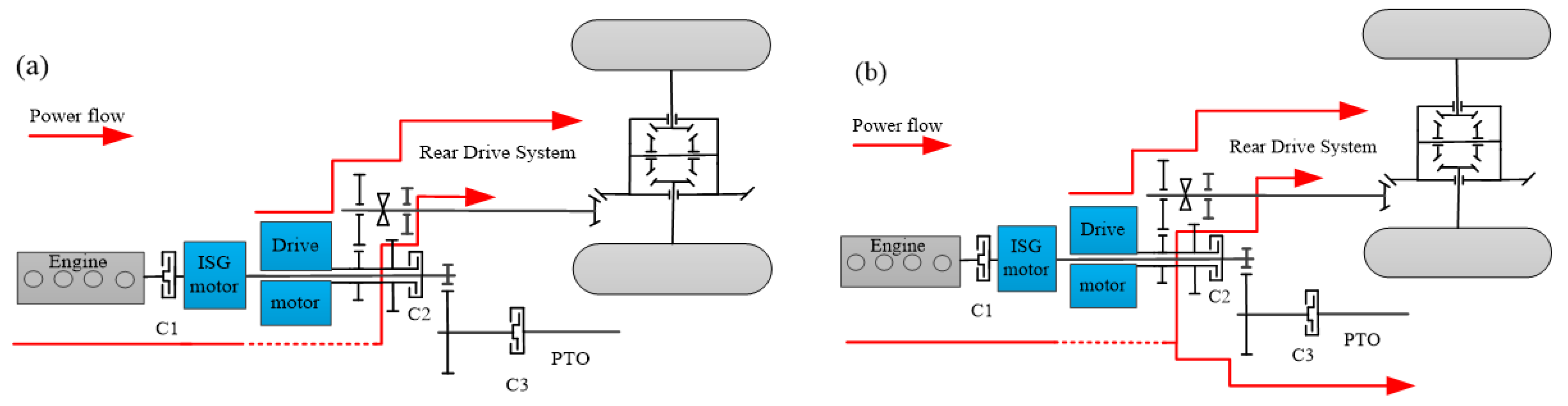
To enhance the adaptability aspects of operation tasks and the feasibility of the mechanical system of tractors, a CSPT configuration of the tractor is constructed, in which the power takeoff (PTO) and front and rear driveshafts could output power independently.
(2)
A real-time energy management strategy for the CSPT is proposed with the ECMS method. The energy requirement can be allocated among three power units to the current tractor states, fully considering the overall efficiency in rotary tillage working conditions.
(3)
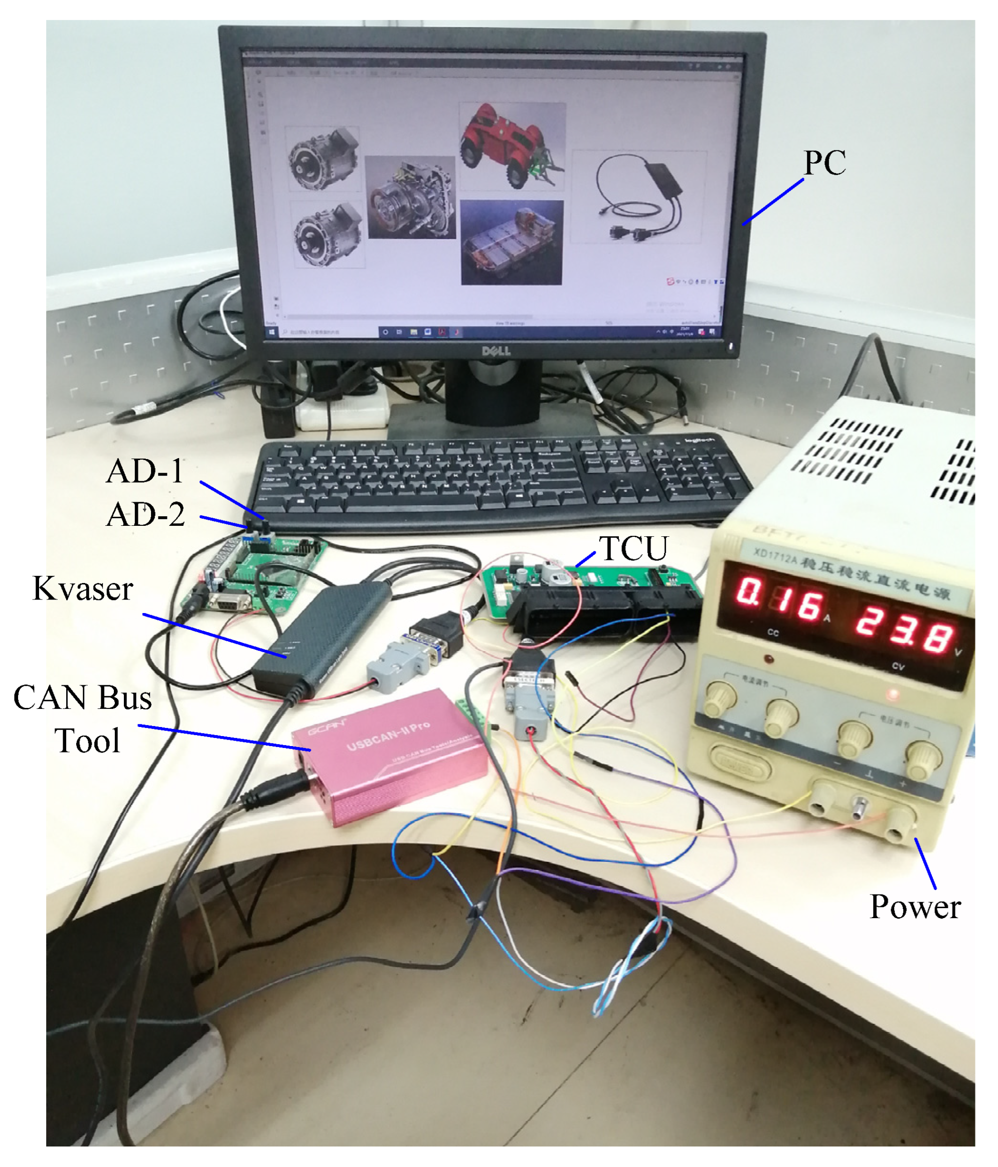
To realize the ECMS in real time, the radial basis function neural network is used to predict the demand power of the tractor in rotary tillage conditions. Additionally, this section is conducted using edge computing. Furthermore, the hardware-in-loop experiment is implemented to validate the executability of the proposed EMS.

2. Configuration Design and Multimode Analysis of Tractor

2.1. Power Flow Modeling and Configuration of Coupled-Split Powertrains

The new tractors’ power system with coupled-split powertrains consisted of an engine, an integrated starter and generator (ISG) motor, and parallel connections linked with clutch one (C1). As shown in Figure 1, in detail, the drive motor and ISG motor were connected with clutch two (C2). The power of the drive motor was used for the rear drive system, and the engine was mainly used for driving the PTO system that provided power for the rotary tillage machines. The torque or speed coupling occurred on an output shaft of the drive motor with the help of C2. The gear rear drive system was composed of: 1—a low gear; 2—a synchronizer; 3—a high gear. Meanwhile, the output shaft of the ISG motor or engine was the source power for both the tractor’s PTO and rear drive system. Selected through the rotational speed of the rotary tillage, the gear system of the PTO consisted of: 5—a low gear; 6—a synchronizer; 7—an intermediate gear. In addition, the braking or connection of power to the PTO was determined with clutch three (C3). The dual-power of the engine and the motor were coupled or decoupled from one another, in which the output shafts were divided into a rear drive system used to drive the tractor and PTO was transferred to agricultural machinery.
Modeling a CSPT was the main process for expressing the power flow and power configuration form, which consisted of the ISG motor, the drive motor, and the engine. Due to CSPTs working in heavy and complex nonroad farmland conditions, the purpose of parameter matching should have satisfied the requirements of various working conditions, such as rotary tillage, plow, transfer, etc. Although CSPTs mostly work in fields, the balance of vehicle longitudinal dynamics is followed as well. The most different point between a vehicle and a tractor is that the tractor is a kind of work tool for offroad farmlands. Additionally, the main power is used in traction and rotary tillage conditions. The traction supplied by the power unit F T was used to overcome rolling resistance, traction resistance, air friction, and push vehicle acceleration. Then, the formula expressing the dynamic model was presented as Equation (1). The power came from the drive motor and was transmitted into the wheels, but the engine’s power was the power of the PTO system, respectively. The parameters mainly involved in CSPTs are shown in Appendix A.
m v ˙ = F D F T - μ m g cos α 1 2 ρ A C d v 2
P i n = P d e m η a
P d e m = T d e m w w
w w = v r

2.2. The Dynamic Model Analysis of Driving Modes

When the tractor was working on a structured road or in low-load conditions, the drive motor was engaged in the drive system. The state of clutches (C1, C2, and C3) did not work. In the meantime, the synchronizer was combined in a high gear or low gear that ensured the efficiency range of the drive motor was as high as possible. Figure 2a shows the energy flow path of the single motor one (SM1) mode. The dynamic model of the transmission system in this mode was given by [23]:
{ I w w ˙ w + I d w ˙ d i 2 i 0 = T d i 2 η 2 i 0 η 0 T d e m w d = w w i 2 i 0
In the case of the rotary tillage operation mode, the drive motor engaged the power of a rear drive system, and the ISG motor (or the engine) worked as a PTO power source. The tractor worked in the field, which is considered to be an unstructured road. In this situation, C1 and C2 were disengaged, but C3 was engaged. Meanwhile, the drive motor and ISG motor worked in speed mode, and the two power sources were decoupled. The power flow of decoupling was denoted as single motor two (SM2), and is shown in Figure 2b. The dynamic model of the transmission system in SM2 was as follows:
{ I w w ˙ w + I d w ˙ d i 2 i 0 = T d i 2 η 2 η 0 i 0 T dem I i w ˙ i i 4 = T i i 4 η 4 T pto
{ w d = w w i 2 i 0 w i = w pto i 4
The tractor operated under a heavy load in plow mode, and the engine (or ISG motor) and the drive motor could be coupled with C2. C3 was not engaged. Furthermore, the motors worked in the torque coupled (TC) mode, which was used for dragging agricultural plow machinery. The power flow of the TC mode is shown in Figure 3a. The dynamic model was obtained as follows:
{ I w w ˙ w + ( I d w ˙ d + I i w ˙ i ) i 2 i 0 = ( T d + T i ) i 2 η 2 η 0 i 0 T dem w i = w d = w w i 2 i 0
In rotary tillage working conditions, with great resistance caused by load, the engine would engage in a rear drive system and PTO. The clutches (C1, C2, and C3) participated; moreover, the dual-power system was totally engaged. Similarly, the ISG motor worked in the speed or alternator mode, used to adjust the engine working area to maintain the engine’s efficiency, and the drive motor was in torque mode; therefore, this power flow configuration was marked as the speed–torque coupling (STC). The power flow is shown in Figure 3b. Additionally, the dynamic model of the STC driving mode was obtained:
I w w ˙ w + ( I d w ˙ d + I i w ˙ i + I e w ˙ e ) i 2 i 0 = ( T d + T e ± T i ) i 2 η 2 η 0 i 0 T pto T dem
{ w d = w i = w w i 2 i 0 = w pto i 4 w i = w e
As shown in Table 1, the four operation modes could be defined through the working state engine, motors, and clutches. “On” meant that the engine, motors, or clutches were working. “Off” indicated that the components were in a disengaged state. The working point of power units with those modes could be adjusted by the synchronizers, so the efficiency of the power element could be adjusted dynamically according to the matching between the high-efficiency interval of the power units and the load resistance.

3. Parameters Matching

3.1. Parameter Matching of Drive Motors

The CSPT contained two kinds of power sources; furthermore, the structure of those power flows was composed of different configurations of both power units and clutch states. Simultaneously, the working mode of the tractor consisted of rotary tillage, plough, transfer, etc. Therefore, the different driving modes should have satisfied the field conditions to ensure the dynamic demand power of the tractor was met. Especially, a static analysis was used in the parameter matching process that combined the tractor powertrains and driven resistance of the agricultural machinery.
The rated power of the drive motor should have met the requirement of a maximum climbing gradient. Therefore, the rated power of the drive motor was calculated as follows:
P g = v 3600 η a ( m g sin α max + μ m g cos α max + 1 2 ρ A C d v 2 )
On the other hand, to overcome the traction resistance and rolling resistance, the drive motor should have met the rated load of the plow operation. The rated power of the drive motor should have met the following relationship:
{ F T = z b 0 h 0 k 0 F f = f m g cos α P T = ( F t + F f ) v t 3600
Therefore, the rated power of the drive motor should have mostly satisfied low-load working conditions, and the coupling mode was engaged in extremely increased loads, for which the external power demand could be supplied through the ISG motor or engine. Therefore, the main parameters of the plow operation mode were determined and shown in Table 2.
P d = max ( P g , P T )

3.2. Parameter Matching of Engine and ISG Motor

In rotary tillage tractor conditions, the engine was specially configured for PTO. According to the empirical formula in rotary tillage operation mode, the power consumed due to the conditions was provided by the engine. The engine power was determined through the consumption of rotary tillage tools; the ISG motor acted as a power adjustment unit to push the engine or drive motor to work at a highly efficient range.
The consumption power of a rotary tillage tractor was expressed in:
P x = 0.1 ( K g K 1 K 2 K 3 K 4 ) h v B
In heavy-load working conditions, the ISG motor would engage in the coupling mode. Therefore, the reserve traction power and reserve rotary tillage power coefficient were defined as 0.3 and 0.25, respectively. Furthermore, the peak power of the ISG motor was given as follows:
{ P e + P i 1 = 1.3 P x P i 1 = 0.3 P x P d + P i 2 = 1.25 max ( P T , P g ) P i 2 = 0.25 max ( P T , P g ) P i = max ( P i 1 , P i 2 )
It was appropriate for the configuration of the ISG motor to provide additional torque without passing the reducer, as well as being of carrying fewer batteries. Fundamentally, the source of power came from the ISG motor’s driving mode or power generation mode. The motor and engine numerical models were established through a test bench. Additionally, efficiency data of the motor revealing the torque corresponded to different speeds, which were calculated as the motor efficiency was measured using the test platform. Additionally, the main parameters of the rotary tillage operation mode are defined and shown in Table 3.

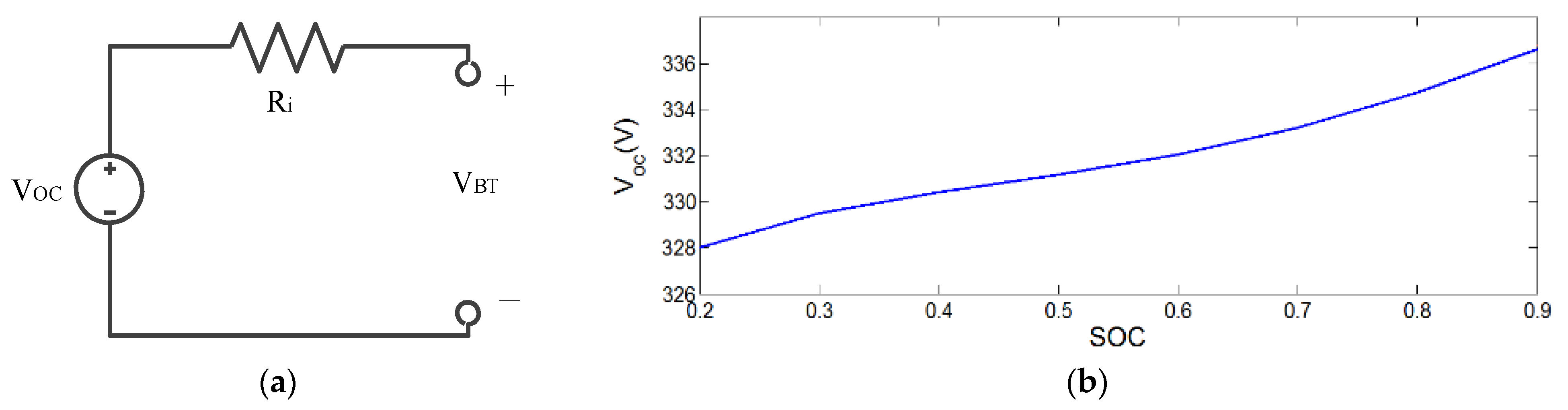
3.3. Parameter Matching of Battery-Rated Power

The battery voltage lever had to match the drive motor controller (230–400 V). Lithium iron phosphate batteries were used in the battery package, and the opening circuit voltage of the battery V BT was selected to be 340 V, which was defined by the motor control unit. Moreover, the power consumed in the plow mode was used to determine the batteries’ endurance.
{ W b = V B T C 1000 W b P d t w
Therefore, the capacity of the battery that satisfied the tractor’s endurance time in plow mode was obtained. Additionally, the main parameters of the battery pack are shown in Table 4. Moreover, to ensure the power units worked in high-efficiency intervals in most working conditions, the transmission ratio of the transmission case was determined as well.
C = 1000 P d t w V BT η b
Lithium iron phosphate batteries were used in the electric power system using the established Rint model [26], and a generous amount of battery cells comprised the electric power system. According to Ohm’s law, the diagram of the equivalent circuit diagram is shown in Figure 4a. The open-circuit voltage and current were expressed in the following:
V B T ( S O C , I B T ) = V O C ( S O C ) R i ( S O C , s i g n ( I B T ) ) I B T
The open voltage of the battery power was related to the state-of-charge (SOC). Furthermore, the voltage of the open circuit VOC was measured with the battery discharge, along with the different states of SOC. Additionally, the experiment carried on at an ambient temperature. According to Equation (18), the battery power of the output could be obtained as follows:
P BT = V BT I BT = V OC I BT R i I BT 2
The Ri is the initial resistance of the battery, and IBT is the output current of the battery, which could be calculated using the following:
I B T = V O C ( S O C ) - V O C 2 ( S O C ) - 4 R i ( S O C , s i g n ( I B T ) ) P B T 2 R i ( S O C , s i g n ( I B T ) )
Thus, the state equation of the SOC was presented as follows [27]:
S O C ( k ) = 1 Q 0 k 1 k I B T ( S O C ( k 1 ) , s i g n ( P B T ) ) d t + S O C ( k 1 )
where Q0 is the maximum capacity of the battery and SOC(k) is the SOC of k at that moment in time.

4. Energy Management Strategy in Rotary Tillage Working Conditions

4.1. Power Demand Forecasts in Rotary Tillage Conditions

The tractor had the feature of being able to slowly change speeds, so the power demand for both the tractor travelling and implemented driving was repeated regularly. What is more, an excellent prediction of a future power demand could greatly contribute to the energy management strategy [28]. In this paper, rotary tillage conditions were conducted as shown in Figure 5b. This was only one driving cycle, and a large number of repeated driving cycles proceeded in the field. Following this, a power demand prediction based on the radial basis function neural network (RBF-NN) was proposed. It was used in the equivalent consumption minimization strategy to allocate a short-term supply of future power. The structure of the three-layer RBF-NN is shown in Figure 5a. The input layer was used to receive the system input parameters, which included the tractors’ speed and acceleration, rotary tillage depth, and resistance coefficient. For the of work tools part, the rotary tillage depth and resistance coefficient were collected in the driving cycle. The output layer of the RBF-NN was determined as the power demand [29]. Additionally, the hidden layer depicted the nonlinearities of the input/output relationship. Specifically, the Gaussian function was used as the RBF-NN, and could be formulated as:
y j = i = 1 h w i j e ( | | x - c i | | 2 2 σ ) j = 1 , 2 , p
where y j is the output of the network, w i j and x are the weight and input parameters, respectively, c i and σ are the neural network center and propagation width, respectively, h is the number of hidden layer nodes, and p is the number of output nodes. The number h of hidden layer nodes was set as 25 in this paper. Additionally, one output node was the predicted power demand for the rotary tillage conditions.
In the actual tractor working conditions, the historical data, such as tractor acceleration, rotating tillage depth, and resistance parameters of the soil, were collected, in which the time interval of those data was 1 s. Additionally, the neural network predicted the power demand in the next 30 s. The neural network was trained online with the help of edge computing once a second, using the sample data in the last 300 s. The power demand was transmitted to the ECMS as a constraint that the ECMS would further distribute the engine and motor power. The scheme of the energy management strategy is shown in Figure 5c.

4.2. Energy Management Strategy Based on Predictive Demand Power

For the tractor mileage and demand power to be known in advance, the equivalent fuel consumption minimization strategy could be used in the global optimization of the fuel and electric power allocation. In the process of optimization, the fuel consumption equivalence factor was defined as follows:
m ˙ e q v ( t , u ) = m ˙ f ( t , u ) + s ( t ) P b ( t , u ) Q l h v
where s(t) is the equivalent factor of converting electric energy consumption into fuel consumption, Q l h v is the low calorific value of fuel, P b ( t , u ) is the electric power input or output from the battery, and m ˙ f ( t , u ) is the actual fuel consumption rate. Additionally, Equation (23) could be solved using Pontryagin’s minimum principle (PMP). Further, the Hamilton function could be built as:
H ( S O C ( t ) , P e n g ( t ) , t ) = m ˙ f ( P e ( t ) ) + λ ( t ) S O ˙ C ( t )
According to the PMP, the purpose of solving the Hamilton function is to determine the optimal control variables, ensuring the fuel economy of the tractor in rotary tillage.
u ( t ) = arg min H ( S O C ( t ) , P e ( t ) , t )
where λ(t) is the costate. The dynamic equation of the battery could be expressed as follows:
S O ˙ C ( t ) = H λ = V O C ( S O C ) - V O C 2 ( S O C ) - 4 R i ( S O C , s i g n ( I B T ) ) P B T 2 Q b R i ( S O C , s i g n ( I B T ) )
S O ˙ C ( t ) = I B T Q b
I B T = P i s g ( u , t ) + P d ( u , t ) V O C
s ( t ) = λ Q l h v Q b V O C
Additionally, the cost function could be defined as follows:
min   J d = t 0 t f [ m ˙ f ( t , u ) + s ( t ) P b ( t , u ) Q l h v ] d t
m ˙ f u e l is the fuel consumption rate, and could be modeled as follows:
m ˙ f ( t ) = 1000 P e ( t ) η e Q l h v
The relationship between the motor power and equivalence factor s(t) was determined using curve fitting, and could be expressed as follows:
s ( t ) = a e - b P d / i s g + c
where a equals 7.135, b equals 0.158, and c equals 2.829, which was a conversion between fuel and electric only, and did not consider the constraint in the dynamic operation of the tractor. The curve fitting between the motor power and equivalence factor s(t) is shown in Figure 6.
In the period of optimization, the constraints in the SOC, maximum speed, and torque of the engine and motor should have been constrained. Therefore, the constraints were expressed as follows:
{ ω i _ min ω i ( t ) ω i _ max ω d _ min ω d ( t ) ω d _ max 0 ω e ( t ) ω e _ max T i _ min T i T i _ max T d _ min T d T d _ max 0 T e T e _ max S O C min S O C ( t ) S O C max

4.3. Equivalence Factor Optimization Based on Genetic Algorithm

The genetic algorithm (GA) was used to optimize the equivalence factor s(t) in which to balance the engine fuel and electric energy consumption. The target of the energy management strategy process should have improved both the fuel economy and the electric economy. The objective function was determined using Equation (30), which satisfied the dynamic demand of the tractor. Additionally, the tractor cyclic condition was conducted in Figure 5b. The process of the GA is shown in Figure 7a, and the result of the optimized equivalent factor s(t) is shown in Figure 7b, which was converted to a lookup table and used in online optimization.
In Figure 7b, the SOC declined with the growth in mileage. Additionally, the equivalence factor was a relatively high value in the lower SOC stage, which indicated the fuel stage to have become more feasible. On the contrary, in the stage of high SOC, the equivalent factors were relatively low values, which revealed that electric energy was more suitable.

5. Results and Discussion

5.1. The Accuracy of Power Demand Prediction Based on RBF

Since the tractor driver habits were traceable, such as the driving speed of the tractor fluctuating within a small range, the width of plowing was a fixed and slow change in acceleration. The prediction of the power demand in tractor plowing was predictable. The results of the predicted power demand using the RBF-NN are shown in Figure 8. This was a foundation of the EMS formulation. The root means square error between the actual power requirements and the predicted power demand was controlled within 1.5 kW, which indicated that there was an error of less than 1% in the forecasting. The parameters of the predicted power demand were collected once per second in real time, such as the tractor speed, acceleration, rotary tillage depth, and soil resistance coefficient. The prediction domain of the power demand in rotary tillage conditions was 5s in the next stage.

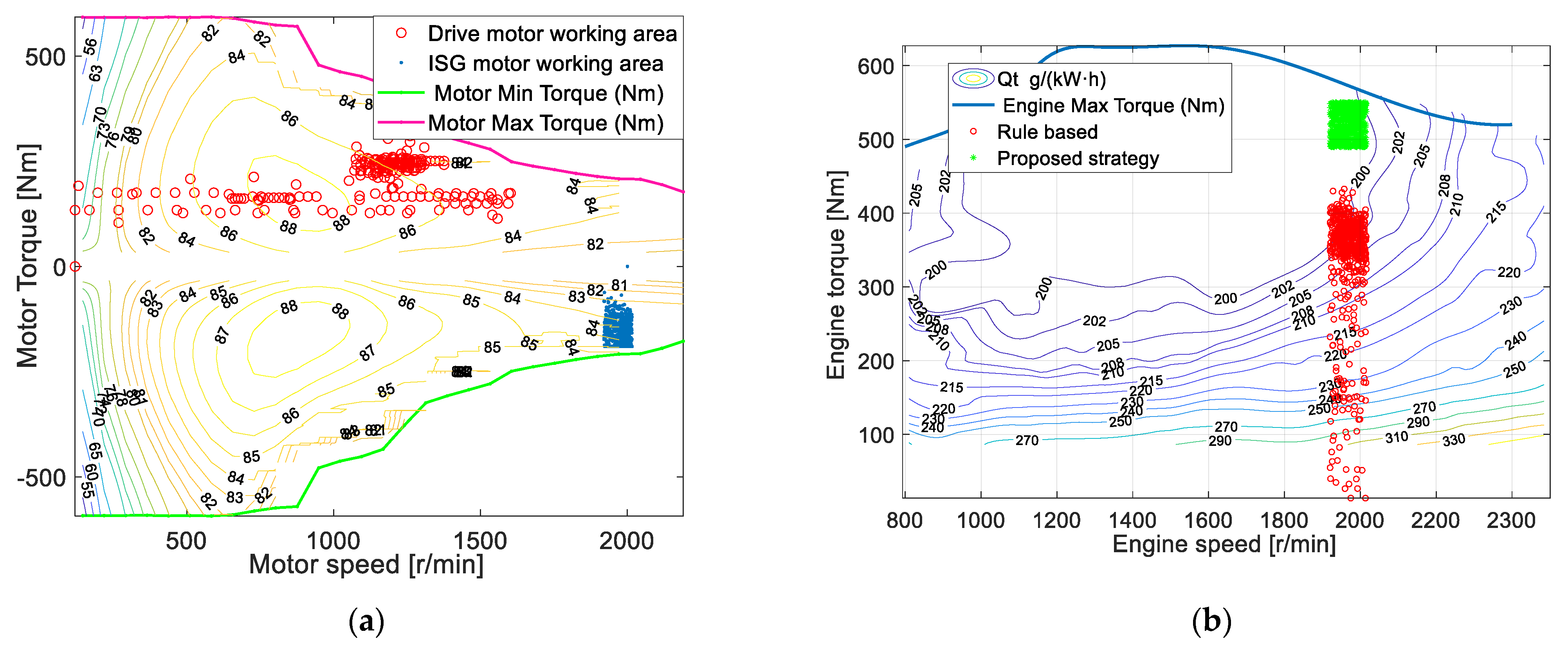
5.2. Simulation Results and Discussion

The hardware-in-loop (HIL) system was designed in this work to test the performance of the ECMS described in previous sections. The mathematical model of the CSPT was built on a personal computer (PC), which included a dual motor, battery system, and a driven and load model of a tractor. The control strategy was implemented in the TCU and compiled with C language. Furthermore, the signals of the acceleration and brake pedals were replaced with an analog-to-digital (AD) converter and simulated using AD-1 and AD-2, as shown in Figure 9. Additionally, the TCU was powered with a 24 V direct current; in addition, the TCU and ADs were connected with the CSPT model through Kvaser, which is a USB-CAN analysis tool. Moreover, the CAN bus tool was used to check the validity of the data.
The corresponding TCU control strategy was downloaded through an advanced RISC machine (ARM) simulator, with software having been compiled prior to this. The TCU connected with the CSPT model with the help of the CAN interface, and the baud rate was 500 kb/s. Additionally, another CAN communication interface was used to receive acceleration and brake pedal signals with 12-bit precision AD converter. The TCU was programmed to allocate the torque of each power unit to the CAN network every 10 ms.
The HIL experiment was used to verify the real-time performance of the ECMS. The power demand based on the radial basis function network algorithm was a known quantity for transmitting to the TCU; then, the TCU allocated the output power of each power unit. In rotary tillage working conditions, the output shaft of the PTO was at a constant speed range, which was allocated by using the operation requirements, such as 650–1000 rpm. The tractors’ configuration mode was constructed as shown in Figure 2b. In the rule-based control strategy section, the engine supplied the power to the PTO and drove the machine, which was defined by the demand power to sustain the dynamic balance between the resistance and driving force. However, the proposed strategy was based on the power demand prediction, and torque distribution was regarded as a cost function that considered the SOC and operating mileage. In the proposed ECMS, the ISG motor worked as a generator and the engine worked in efficient intervals to sustain the economy of the whole tractor. The power demand of the resistance and that which the generator consumed were complementary and constituted the output power of the engine, which was described as motor power generation in dynamic conditions. Additionally, the drive motor played a role in driving the rear and forward shafts. The results of the HIL are revealed in Figure 10. The drive motor and ISG motor working areas are shown in Figure 10a. Figure 10b shows the engine working area regarding the proposed strategy. The HIL test of the control strategy verified the real-time performance of the ECMS.
Regarding the energy consumption of the tractors, Figure 11a compared the equivalent fuel consumption of the rule-based control strategy and the proposed strategy. The results showed that the proposed strategy in rotary tillage operation had a lower fuel economy that reduced the fuel consumption by 8.4%, but during the acceleration and deceleration phase, the proposed strategy was similar to the rule-based control strategy. During rotary tillage operating at relatively high speeds, the proposed strategy was more feasible. Figure 11b shows the SOC curve between the rule-based strategy and the proposed strategy, which indicated that the proposed strategy gave attention to both the electric power consumption and fuel consumption.

6. Conclusions

This paper proposed a new coupled-split powertrain tractor between the drive system and PTO that had the same performance as the complex CVT system. To satisfy the power demand in the different rotary tillage levels, the plow operation mode, work in high-efficiency power units, and the power unit parameters of the proposed configuration were defined. Moreover, the EMS of the tractor in rotary tillage operation was proposed. For the online energy distribution, the power demand forecasting using an algorithm for the RBF-NN was obtained. The ECMS was used to distribute power between the engine, the ISG motor, and the drive motor, where the ISG motor accompanied in the generator mode. The specific work could be summarized in the following aspects:
(1)
In this paper, a new powertrains configuration of an agriculture engineering tractor was proposed. Additionally, the parameters of the CSPTs with different powertrains were determined, and the power demand in most kinds of working conditions was satisfied. The ISG motor and drive motor combined power acts as the function of the CVT.
(2)
The RBF-NN was used to predict the power demand of the tractor in rotary tillage. Moreover, the root means square error between the actual power requirements and predicted power demand was controlled within 1.5 kW, which was an error of less than 1% in the forecasting.
(3)
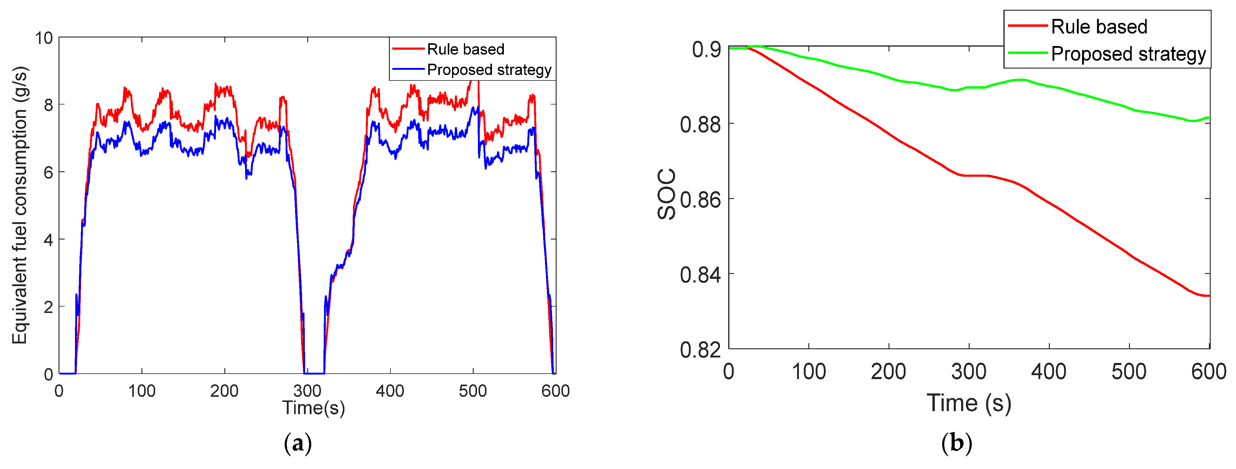
The equivalent factor was optimized with the GA in the energy management strategy conducted online, which indicated that an equivalent fuel consumption in the rotary tillage operation mode was reduced by 8.4%, compared with the rule-based control strategy. With the proposed strategy, the engine could be operated in a high-efficiency range and the ISG motor could extend the cycling mileage in electric power working as a generator. Additionally, coordinating the output power from both the battery and fuel expressed the advantage of the proposed tractor configuration comprehensively.

Author Contributions

Conceptualization, Y.Z. and H.D.; methodology, H.D.; software, Q.A.; validation, H.W.; formal analysis, H.D.; investigation and data curation, Q.A.; writing—original draft preparation, H.D.; writing—review and editing, H.D. All authors have read and agreed to the published version of the manuscript.

Funding

This research was in part supported by the National Natural Science Foundation of China under grant 52202461, in part by the fellowship of the China Postdoctoral Science Foundation under grants 2022TQ0032 and 2022M710380, and in part by the Anhui Engineering Technology Research Center for Automotive New Technology under grant QCKJ202202A.

Conflicts of Interest

The authors declare no conflict of interest.

Appendix A

Table A1. Tractor Parameters Involved.
SymbolParameterValue/Unit
AVehicle lateral surface3.5 m2
CBattery capacity Ah
CdAerodynamic coefficient0.73
F D The driving force of the power systemN
F f The rolling resistanceN
F T The demand driving force in plow conditionsN
IBTElectric currentA
I d Moment of inertia of the drive motorkg/m2
I e Moment of inertia of the engine kg/m2
I i Moment of inertia of the ISG motorkg/m2
I w Moment of inertia of the wheelkg/m2
mThe mass of in using8690 kg
PBTElectric power of the batterykW
PdemThe output power of the final drivekW
P d The power of the drive motorkW
P e The power of the enginekW
P g The power of the drive motor satisfies the maximum climbing gradient kW
PinInput power of the powertrainkW
P i The power of the ISG motorkW
P x The demand power in rotary tillage conditionskW
Q0Maximum battery chargeC
rTire radius0.654 m
RiThe internal resistance of the batteryΩ
T d The torque of the drive motorN·m
TdemThe final drive output torqueN·m
T e The torque of the engineN·m
T i The torque of the ISG motorN·m
T pto The torque of the power take-offN·m
t w Pure battery lifeh
vTractor speedm/s
VBTThe voltage of the loadV
W b Power carried by the batterykWh
VOCOpen-circuit voltageV
w 1 / w 2 Price of gasoline fuel and electricity, respectively
w d The rotational speed of the drive motorrad/s
w e The rotational speed of the enginerad/s
w i The rotational speed of the ISG motorrad/s
w pto The rotational speed of the PTOrad/s
w w The rotational speed of the wheelrad/s
α Climbing gradient°
ρAerodynamic resistance coefficient1.2 kg/m3
fRolling coefficient0.06
η 0 Transmission efficiency of the main reducer%
η 2 Transmission efficiency of high gear of rear drive system%
η a The efficiency of the total transmission0.86
η b Battery discharge efficiency0.9
η ISG / D The efficiency of the ISG motor or drive motor%

References

  1. Zhang, X.; Zou, Y.; Fan, J.; Guo, H. Usage pattern analysis of Beijing private electric vehicles based on real-world data—ScienceDirect. Energy 2019, 167, 1074–1085. [Google Scholar] [CrossRef]
  2. Du, W.; Zhao, S.; Jin, L.; Gao, J.; Zheng, Z. Optimization design and performance comparison of different powertrains of electric vehicles. Mech. Mach. Theory 2020, 156, 104143. [Google Scholar] [CrossRef]
  3. Li, L.; Wang, X.; Song, J. Fuel consumption optimization for smart hybrid electric vehicle during a car-following process. Mech. Syst. Signal Process. 2016, 87, 17–29. [Google Scholar] [CrossRef]
  4. Liu, Y.; Li, Z.; Chen, Y.; Zhao, K. A Novel Fuel-Cell Electric Articulated Vehicle and Its Drop-and-Pull Transport System. Energies 2020, 13, 3632. [Google Scholar] [CrossRef]
  5. Mudarisov, S.; Gainullin, I.; Gabitov, I.; Hasanov, E.; Farhutdinov, I. Soil compaction management: Reduce soil compaction using a chain-track tractor. J. Terramech. 2020, 89, 1–12. [Google Scholar] [CrossRef]
  6. Ghobadpour, A.; Mousazadeh, H.; Kelouwani, S.; Zioui, N.; Kandidayeni, M.; Boulon, L. An intelligent energy management strategy for an off-road plug-in hybrid electric tractor based on farm operation recognition. IET Electr. Syst. Transp. 2021, 11, 333–347. [Google Scholar] [CrossRef]
  7. Zhang, Y.; Xu, H.; Liu, H.; Qi, S. Research on the Evaluation Index of Handling Stability of Tractor and Double Trailer Combination. China J. Highw. Transp. 2017, 30, 145–151. [Google Scholar]
  8. Abotabik, M.; Meyer, R.T. Switched Optimal Control of a Heavy-Duty Hybrid Vehicle. Energies 2021, 14, 6736. [Google Scholar] [CrossRef]
  9. Mocera, F. A Model-Based Design Approach for a Parallel Hybrid Electric Tractor Energy Management Strategy Using Hardware in the Loop Technique. Vehicles 2020, 3, 1–19. [Google Scholar] [CrossRef]
  10. Hu, J.; Zu, G.; Jia, M.; Niu, X. Parameter matching and optimal energy management for a novel dual-motor multi-modes powertrain system. Mech. Syst. Signal Process. 2019, 116, 113–128. [Google Scholar] [CrossRef]
  11. Song, P.; Lei, Y.; Fu, Y. Multi-Objective Optimization and Matching of Power Source for PHEV Based on Genetic Algorithm. Energies 2020, 13, 1127. [Google Scholar] [CrossRef]
  12. Yong, Z.; Lin, Z. Parameter matching theory of hybrid track-type bulldozer power system. In Proceedings of the World Automation Congress, Puerto Vallarta, Mexico, 24–28 June 2012. [Google Scholar]
  13. Chen, Y.; Xie, B.; Du, Y.; Mao, E. Powertrain parameter matching and optimal design of dual-motor driven electric tractor. Int. J. Agric. Biol. Eng. 2019, 12, 33–41. [Google Scholar] [CrossRef] [Green Version]
  14. Qu, J.; Guo, K.; Zhang, Z.; Song, S.; Li, Y. Coupling Control Strategy and Experiments for Motion Mode Switching of a Novel Electric Chassis. Appl. Sci. 2020, 10, 701. [Google Scholar] [CrossRef] [Green Version]
  15. Barthel, J.; Gorges, D.; Bell, M.; Munch, P. Energy Management for Hybrid Electric Tractors Combining Load Point Shifting, Regeneration and Boost. In Proceedings of the 2014 IEEE Vehicle Power and Propulsion Conference (VPPC), Coimbra, Portugal, 27–30 October 2014. [Google Scholar]
  16. Chen, Z.; Mi, C.C.; Xiong, R.; Xu, J.; You, C. Energy management of a power-split plug-in hybrid electric vehicle based on genetic algorithm and quadratic programming. J. Power Sources 2014, 248, 416–426. [Google Scholar] [CrossRef]
  17. Xu, L.; Zhang, J.; Liu, M.; Zhou, Z.; Liu, C. Control algorithm and energy management strategy for extended range electric tractors. Int. J. Agric. Biol. Eng. 2017, 10, 35–44. [Google Scholar]
  18. Zhou, Q.; Zhang, Y.; Li, Z.; Li, J.; Xu, H.; Olatunbosun, O. Cyber-Physical Energy-Saving Control for Hybrid Aircraft-Towing Tractor based on Online Swarm Intelligent Programming. IEEE Trans. Ind. Inform. 2017, 14, 4149–4158. [Google Scholar] [CrossRef] [Green Version]
  19. Troncon, D.; Alberti, L. Case of Study of the Electrification of a Tractor: Electric Motor Performance Requirements and Design. Energies 2020, 13, 2197. [Google Scholar] [CrossRef]
  20. Wu, Z.; Xie, B.; Li, Z.; Chi, R.; Ren, Z.; Du, Y.; Inoue, E.; Mitsuoka, M.; Okayasu, T.; Hirai, Y. Modelling and verification of driving torque management for electric tractor: Dual-mode driving intention interpretation with torque demand restriction. Biosyst. Eng. 2019, 182, 65–83. [Google Scholar] [CrossRef]
  21. Kim, W.S.; Kim, Y.J.; Kim, Y.S.; Baek, S.Y.; Baek, S.M.; Lee, D.H.; Nam, K.C.; Kim, T.B.; Lee, H.J. Development of Control System for Automated Manual Transmission of 45-kW Agricultural Tractor. Appl. Sci. 2020, 10, 2930. [Google Scholar] [CrossRef] [Green Version]
  22. Li, H.; Song, Z.H.; Xie, B. Plowing Performance Simulation and Analysis for Hybrid Electric Tractor. Appl. Mech. Mater. 2013, 365–366, 505–511. [Google Scholar]
  23. Agyeman, P.K.; Tan, G.; Alex, F.J.; Valiev, J.F.; Owusu-Ansah, P.; Olayode, I.O.; Hassan, M.A. Parameter Matching, Optimization, and Classification of Hybrid Electric Emergency Rescue Vehicles Based on Support Vector Machines. Energies 2022, 15, 7071. [Google Scholar] [CrossRef]
  24. Lagnelöv, O.; Larsson, G.; Nilsson, D.; Larsolle, A.; Hansson, P.A. Performance comparison of charging systems for autonomous electric field tractors using dynamic simulation. Biosyst. Eng. 2020, 194, 121–137. [Google Scholar] [CrossRef]
  25. Niu, P.; Chen, J.; Zhao, J.; Luo, Z. Analysis and evaluation of vibration characteristics of a new type of electric mini-tiller based on vibration test. Int. J. Agric. Biol. Eng. 2019, 12, 106–110. [Google Scholar] [CrossRef]
  26. Yang, Y.; Zhang, Y.; Tian, J.; Zhang, S. Research on a Plug-In Hybrid Electric Bus Energy Management Strategy Considering Drivability. Energies 2018, 11, 2177. [Google Scholar] [CrossRef] [Green Version]
  27. Wei, H.; Zhong, Y.; Fan, L.; Ai, Q.; Zhao, W.; Jing, R.; Zhang, Y. Design and validation of a battery management system for solar-assisted electric vehicles. J. Power Sources 2021, 513, 230531. [Google Scholar] [CrossRef]
  28. Zhang, Y.; Huang, Y.; Chen, Z.; Li, G.; Liu, Y. A Novel Learning Based Model Predictive Control Strategy for Plug-in Hybrid Electric Vehicle. IEEE Trans. Transp. Electrif. 2021, 8, 23–35. [Google Scholar] [CrossRef]
  29. Jinquan, G.; Hongwen, H.; Jiankun, P.; Nana, Z. A novel MPC-based adaptive energy management strategy in plug-in hybrid electric vehicles. Energy 2019, 175, 378–392. [Google Scholar] [CrossRef]
Figure 1. The configuration of the coupled-split power system. (1) Low gear; (2) synchronizer; (3) high gear; (4) rear driveshaft; (5) low gear of PTO; (6) synchronizer; (7) intermediate gear of PTO; (8) PTO.
Machines 10 01175 g001
Figure 2. Power flow in SM1 (a) and SM2 (b) modes.
Machines 10 01175 g002
Figure 3. Power flow in TC (a) and STC (b) modes.
Machines 10 01175 g003
Figure 4. Model of the battery pack. (a) The battery diagram of the equivalent circuit. (b) The correlation between the battery open-circuit voltage and SOC.
Machines 10 01175 g004
Figure 5. The scheme of equivalent consumption minimization strategy. (a) The structure of RBF neural network. (b) The speed curve of tractor rotary tillage. (c) ECMS based on predictive power demand.
Machines 10 01175 g005
Figure 6. The fitting curve between motor power and equivalence factor.
Machines 10 01175 g006
Figure 7. The optimized equivalence factor. (a) The process of GA optimization. (b) Equivalent factors under different SOC and rotary tillage mileages.
Machines 10 01175 g007
Figure 8. Power demand forecasting based on RBF-NN.
Machines 10 01175 g008
Figure 9. Hardware-in-loop test bench.
Machines 10 01175 g009
Figure 10. The working area of power units. (a) The working area of motors in rotary tillage. (b) The working area of the engine in rotary tillage.
Machines 10 01175 g010
Figure 11. The results of the proposed strategy. (a) The optimized equivalent fuel consumption. (b) The SOC curve of battery in rotary tillage conditions.
Machines 10 01175 g011
Table 1. The operation schedule of the dual-power system.
ModesEngineISG MotorDrive MotorC1C2C3
SM1OffOffOnOffOffOff
SM2On/OffOnOnOn/OffOffOn
TCOn/OffOnOnOn/OffOnOff
STCOnOnOnOnOnOn
Table 2. The main parameters of plow operation mode.
ComponentsItemsParameters
Drive motorRated power (kW)65
Rated speed (rpm)2200
Rated torque (Nm)280
Parameters of plow machine [24] f , Rolling resistance coefficient0.06~0.1
z, Number of ploughshares6
b 0 , Plowshare width25 cm
h 0 , Tillage depth20~22 cm
k 0 , Soil proportion resistance4~6 N/cm2
Tractor α max , Maximum climbing gradient15°
M, load weight under transfer conditions9500 kg
Table 3. The main parameters of rotary tillage operation mode.
ComponentsItemsParameters
EngineRated power (kW)145
Rated speed (rpm)2200
Rated torque (Nm)630
ISG motorRated power (kW)50
Rated speed (rpm)2200
Rated torque (Nm)220
Parameters of rotary tillage machine [25]h, rotary tillage depth16~18 cm
B, width length of rotary tillage1.5~1.7 m
K g , proportion resistance of rotary tillage8~10 N/cm2
K 1 , root depth correction coefficient1
K 2 , correction coefficient of soil moisture content0.94
K 3 , correction coefficient of vegetation content in the soil1.1
K 4 , operation mode correction factor0.65
Table 4. The main parameters of battery package and transmission ratio.
ComponentsItemsParameters
Power battery V BT , average operating voltage (V)340
C, rated capacity (Ah)240
Transmission ratio i 0 , the reduction ratio of the main reducer 6.24
i 1 , the reduction ratio of the low-gear of the rear drive system7.23
i 2 , the reduction ratio of the high-gear of the rear drive system2.27
i 3 , the reduction ratio of the low-gear of the PTO2.46
i 4 , the reduction ratio of the intermediate gear of the PTO1.68
Publisher’s Note: MDPI stays neutral with regard to jurisdictional claims in published maps and institutional affiliations.

