
Patient-Specific Stent Fabrication Using a Seven-Degree-of-Freedom Additive Manufacturing System

Abstract
:1. Introduction
1.1. Additive Manufacturing for Patient-Specific Medical Devices
1.2. Limitations of Current Additive Manufacturing Methods
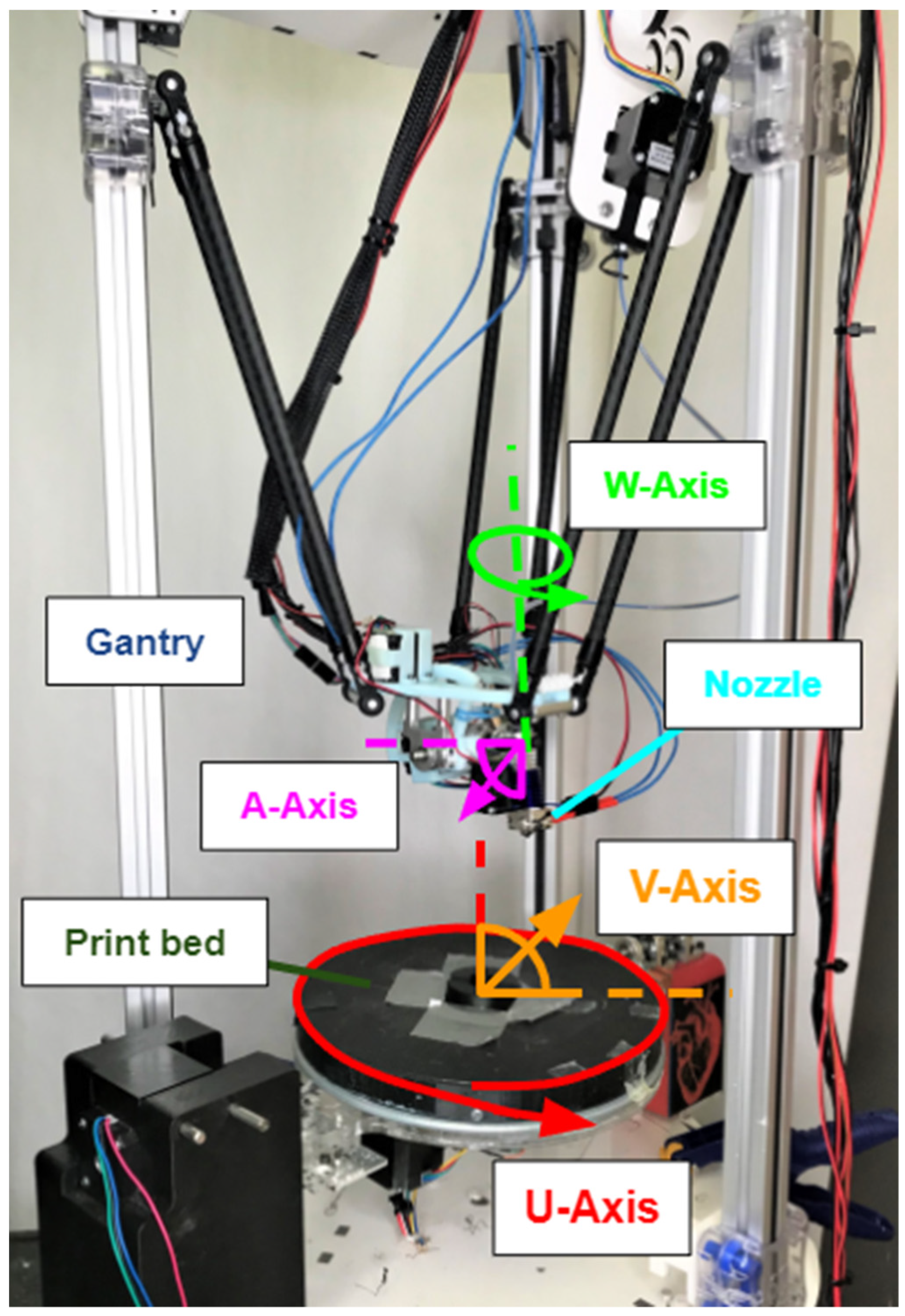
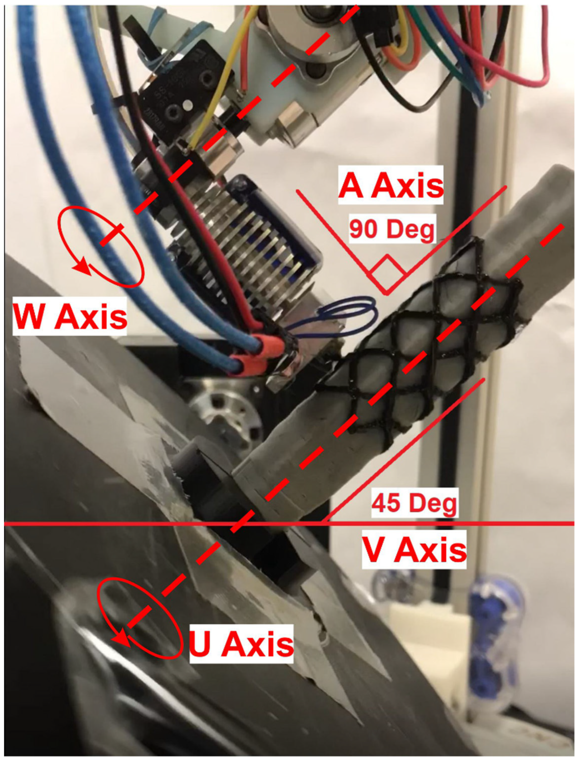
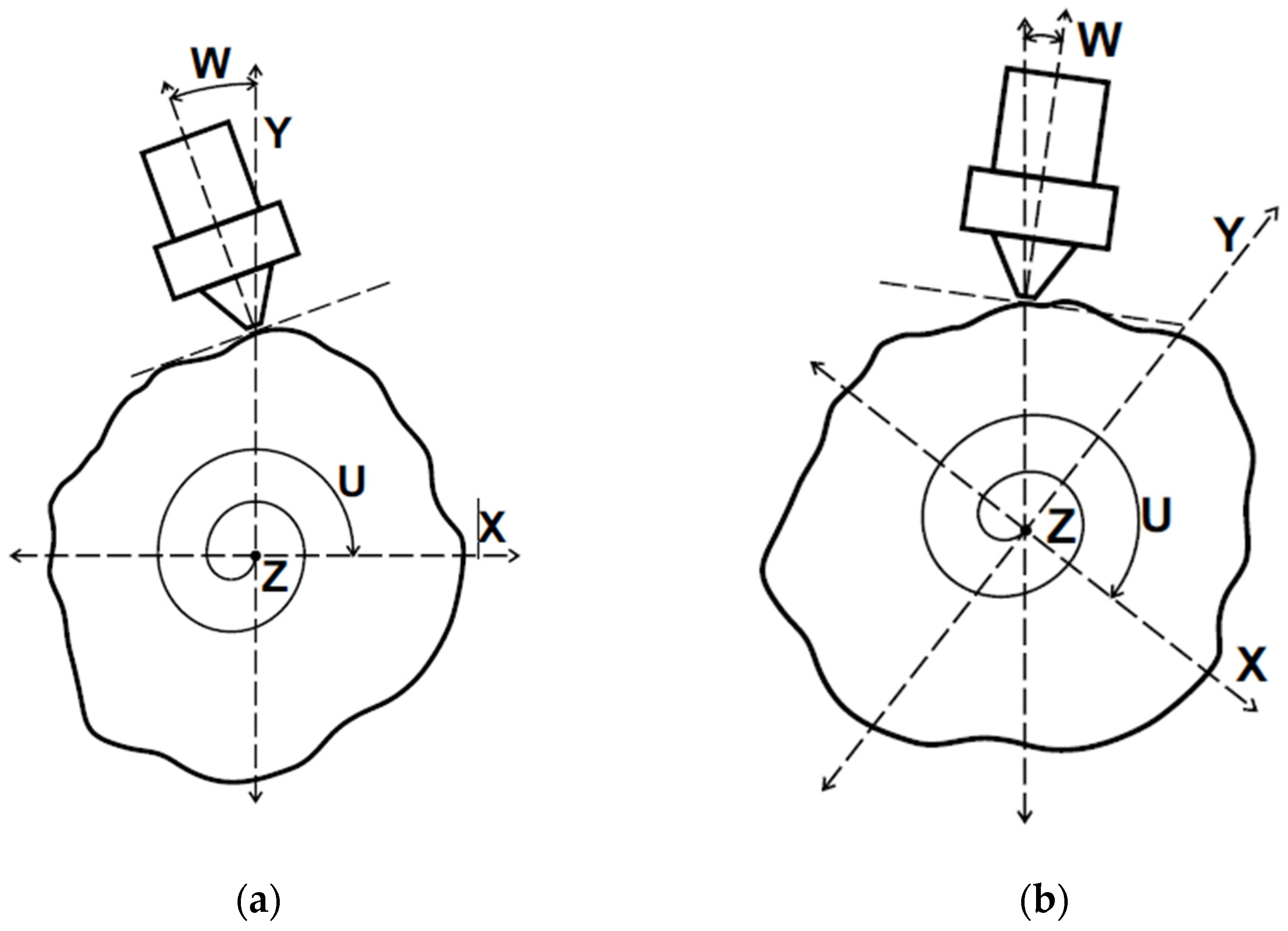
1.3. The Seven-Degree-of-Freedom Additive Manufacturing System
2. Materials and Methods
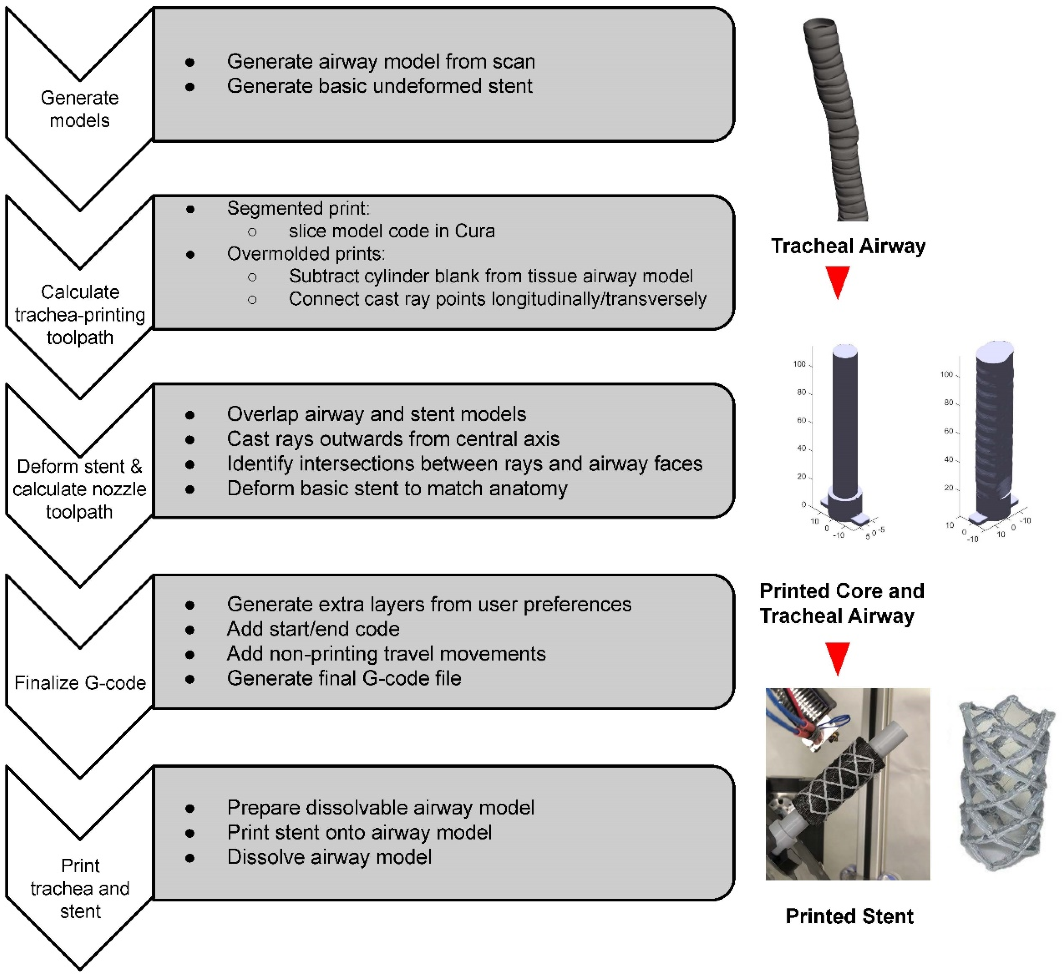
2.1. Overview
2.2. Trachea Model Generation
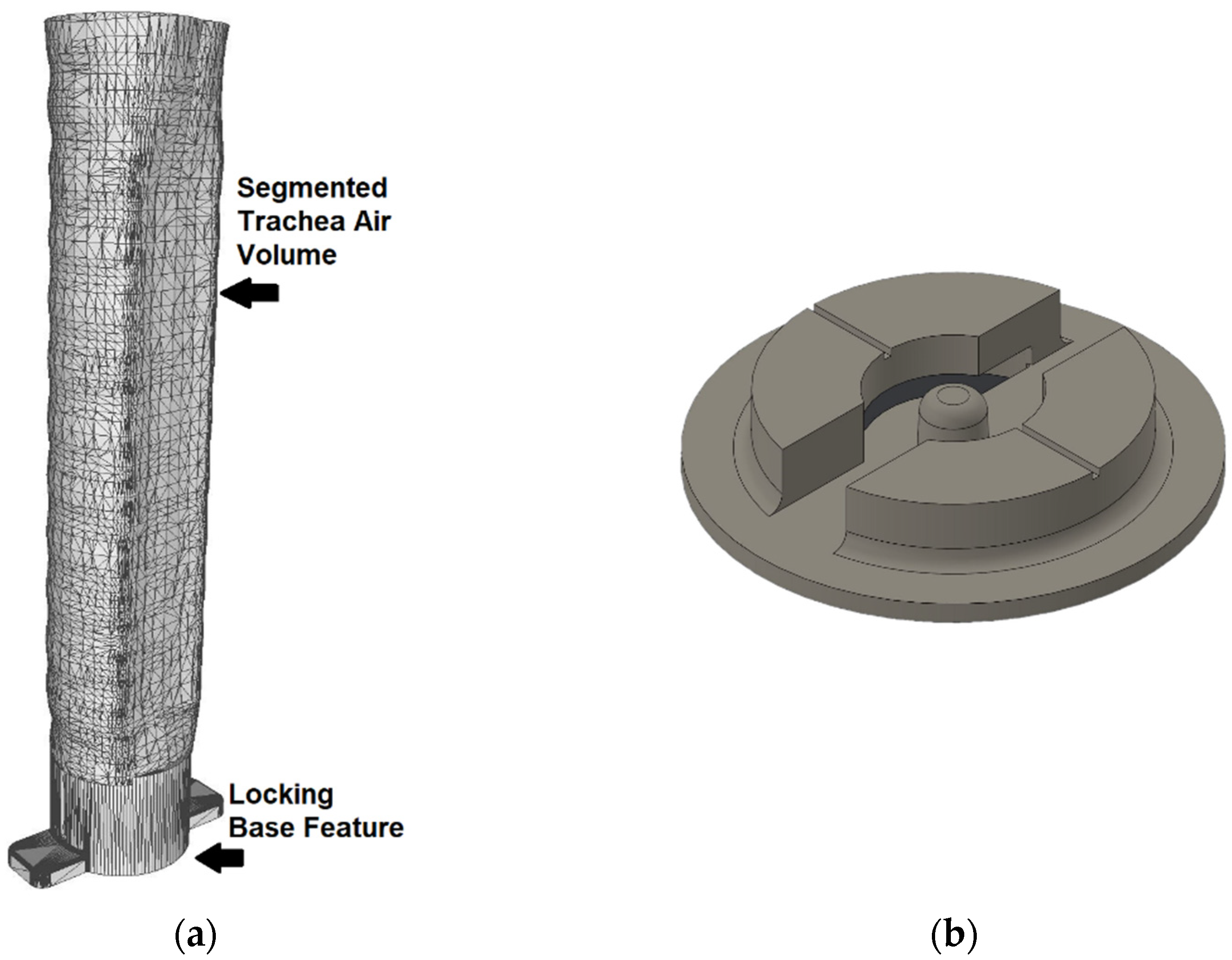
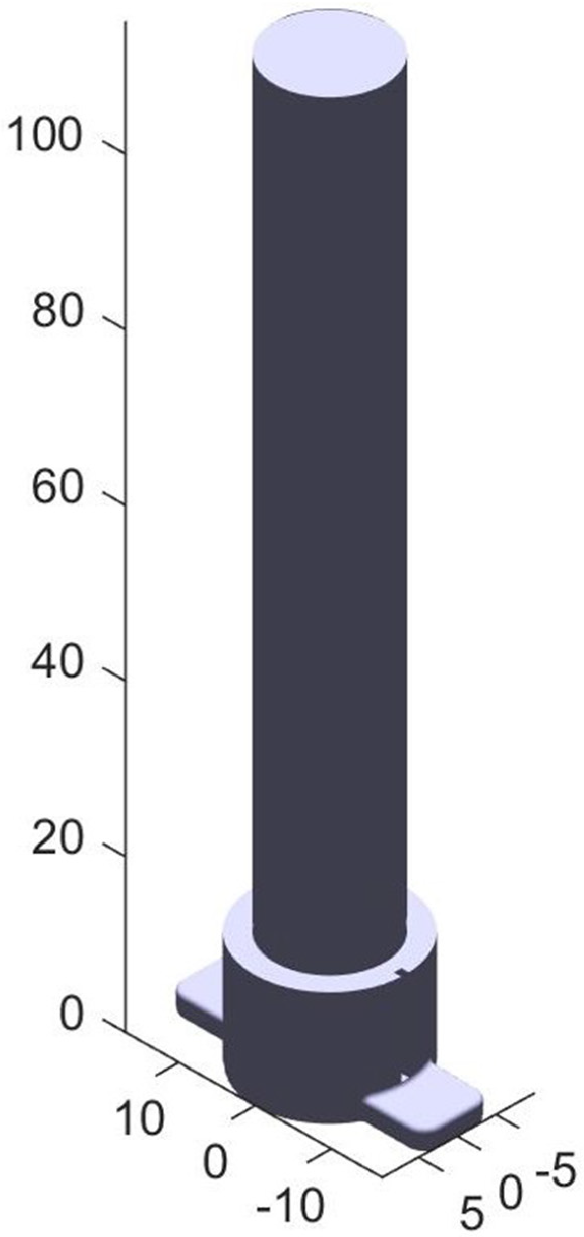
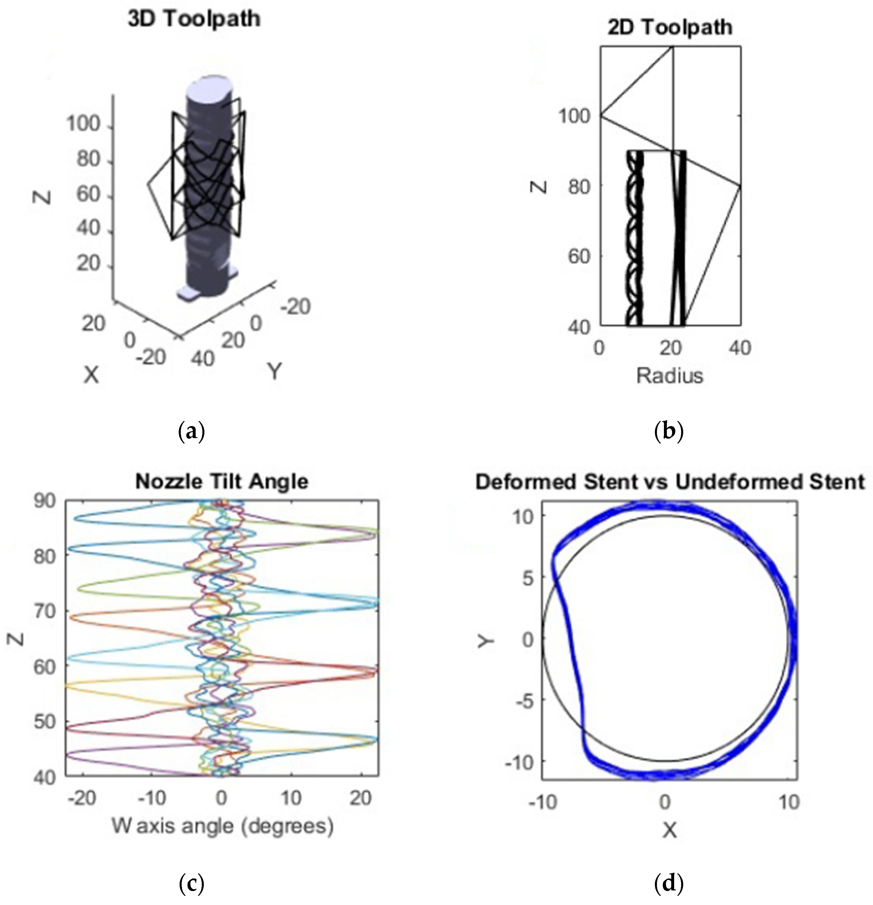
2.3. Toolpath Generation for the Trachea Airway Print
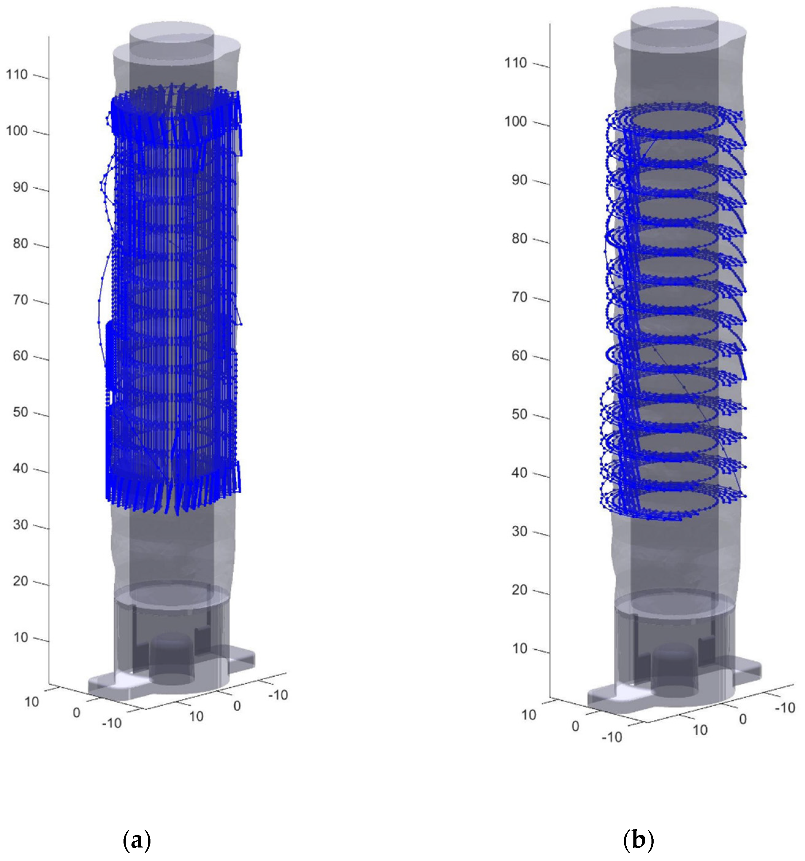
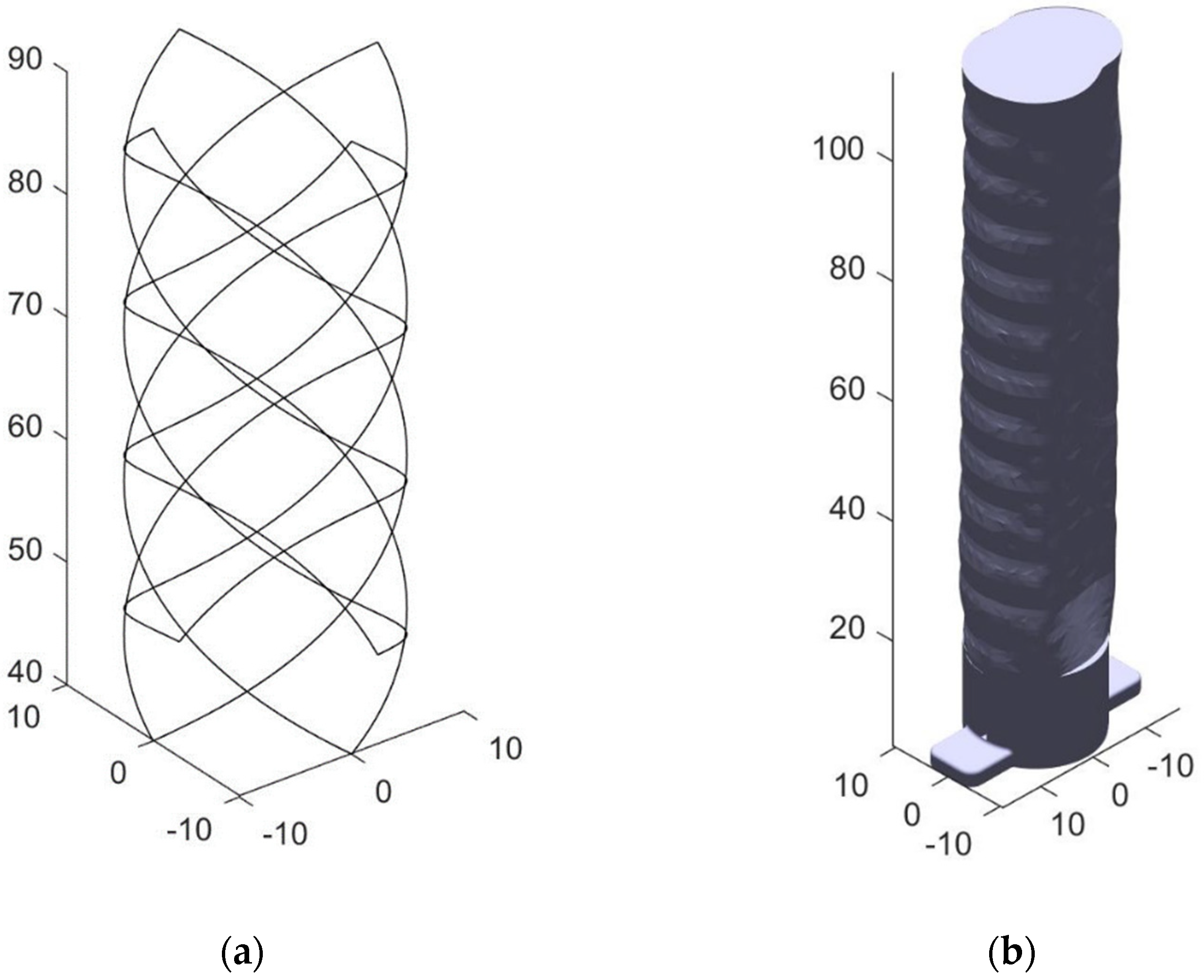
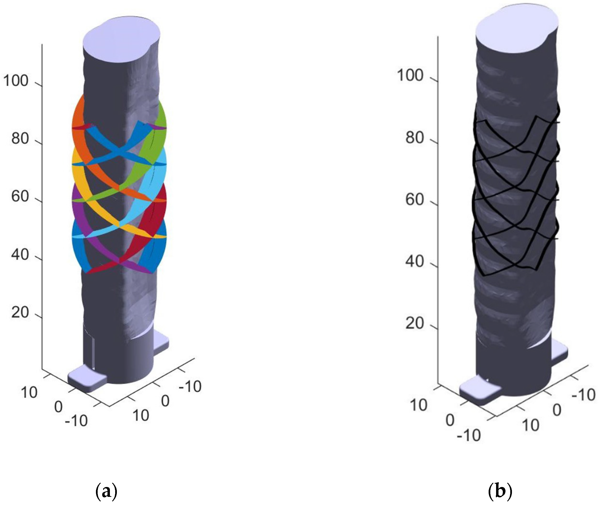
2.4. Stent Model Generation and Transform
2.5. Nozzle Angle Calculation
2.6. G-Code Finalization
2.7. Printing of the Stent
3. Results
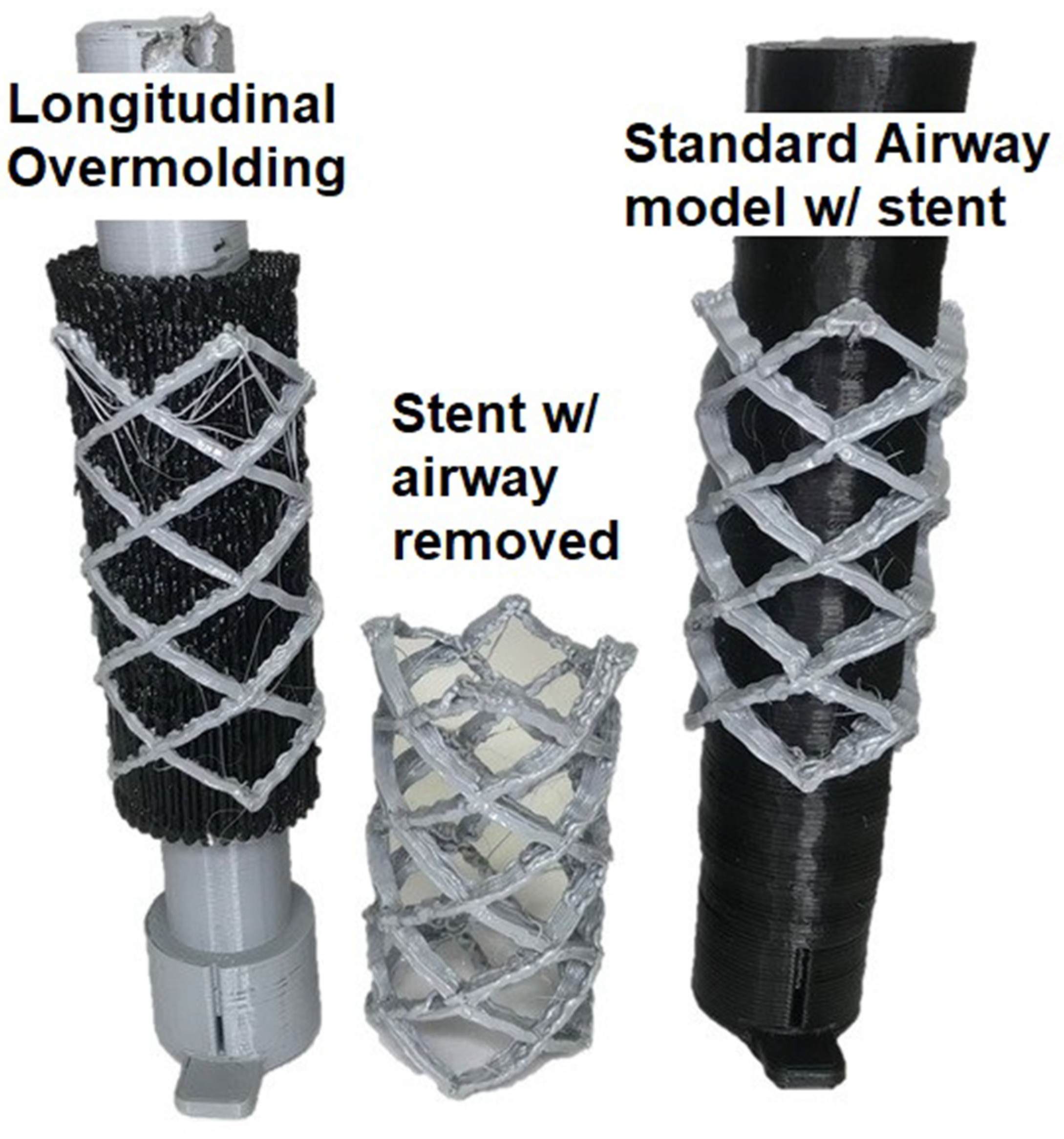
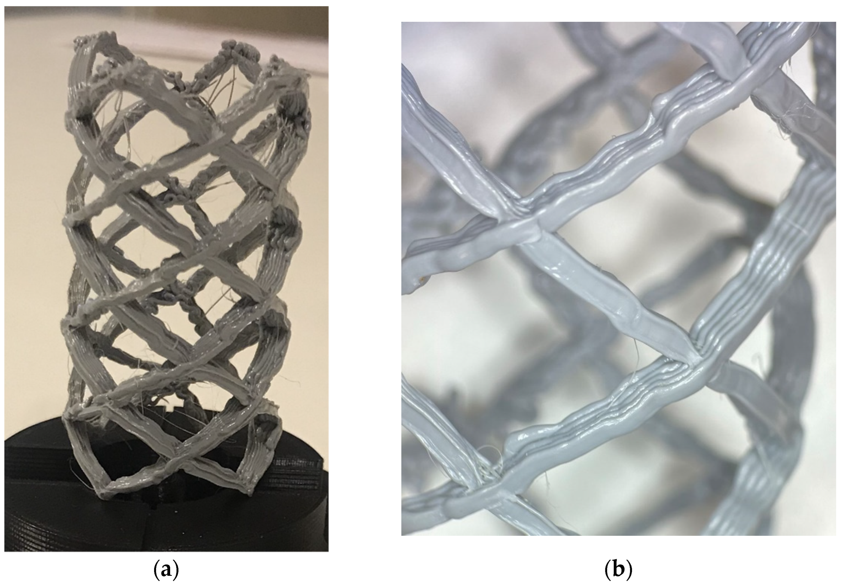
3.1. Stent Print
3.2. Trachea Airway Prints: Mesh Analysis
3.3. Comparisons for Airway and Stent Printing
4. Discussion
4.1. Implications of the Patient-Specific Stent Case Study
4.2. Evaluation of Processes Parallelization
4.3. Current Benefits and Future Directions
5. Conclusions
Supplementary Materials
Author Contributions
Funding
Data Availability Statement
Acknowledgments
Conflicts of Interest
References
- Hafez, M.A.; Moholkar, K. Patient-specific instruments: Advantages and pitfalls. SCIOT-J 2017, 3, 66. [Google Scholar] [CrossRef] [Green Version]
- Gualdrón, C.I.L.; Ibarra, E.R.B.; Bohórquez, A.P.M.; Bohórquez, I.G. Present and future for technologies to develop patient-specific medical devices: A systematic review approach. Med. Devices 2019, 12, 253–273. [Google Scholar] [CrossRef] [PubMed] [Green Version]
- Wong, K.C. 3D-printed patient-specific applications in orthopedics. Orthop. Res. Rev. 2016, 8, 57–66. [Google Scholar] [CrossRef] [PubMed] [Green Version]
- Kolken, H.M.A.; Lietaert, K.; van der Sloten, T.; Pouran, B.; Meynen, A.; Van Loock, G.; Weinans, H.; Scheys, L.; Zadpoor, A.A. Mechanical performance of auxetic meta-biomaterials. J. Mech. Behav. Biomed. Mater. 2020, 104, 103658. [Google Scholar] [CrossRef]
- Gueche, Y.A.; Sanchez-Ballester, N.M.; Cailleaux, S.; Bataille, B.; Soulairol, I. Selective Laser Sintering (SLS), a New Chapter in the Production of Solid Oral Forms (SOFs) by 3D Printing. Pharmaceutics 2021, 13, 1212. [Google Scholar] [CrossRef]
- Tagliaferri, V.; Trovalusci, F.; Guarino, S.; Venettacci, S. Environmental and Economic Analysis of FDM, SLS and MJF Additive Manufacturing Technologies. Materials 2019, 12, 4161. [Google Scholar] [CrossRef] [PubMed] [Green Version]
- Mazzoli, A. Selective laser sintering in biomedical engineering. Med. Biol. Eng. Comput. 2013, 51, 245–256. [Google Scholar] [CrossRef]
- Ventola, C.L. Medical Applications for 3D Printing: Current and Projected Uses. Pharm. Ther. 2014, 39, 704–711. [Google Scholar]
- Melčová, V.; Svoradová, K.; Menčík, P.; Kontárová, S.; Rampichová, M.; Hedvičáková, V.; Sovková, V.; Přikryl, R.; Vojtová, L. FDM 3D Printed Composites for Bone Tissue Engineering Based on Plasticized Poly(3-hydroxybutyrate)/poly(d,l-lactide) Blends. Polymers 2020, 12, 2806. [Google Scholar] [CrossRef]
- Shaqour, B.; Samaro, A.; Verleije, B.; Beyers, K.; Vervaet, C.; Cos, P. Production of Drug Delivery Systems Using Fused Filament Fabrication: A Systematic Review. Pharmaceutics 2020, 12, 517. [Google Scholar] [CrossRef]
- Chen, J.V.; Dang, A.B.C.; Dang, A. Comparing cost and print time estimates for six commercially-available 3D printers obtained through slicing software for clinically relevant anatomical models. 3D Print. Med. 2021, 7, 1. [Google Scholar] [CrossRef] [PubMed]
- Uno, M.; Sugimoto, K.; Taniguchi, I.; Tanaka, K. Six-Degree-of-Freedom Articulated Robot Mechanism and Assembling and Working Apparatus Using Same. U.S. Patent 5,197,846, 30 March 1990. [Google Scholar]
- Zhang, H.; Liu, D.; Huang, T.; Qingxi, H.; Lammer, H. 3D Printing Method of Spatial Curved Surface by Continuous Natural Fiber Reinforced Composite. In Proceedings of the IOP Conference Series: Materials Science and Engineering, Qingdao, China, 28–29 December 2019; IOP Publishing: Bristol, UK, 2020; Volume 782, p. 022059. [Google Scholar]
- Newell, C. Multiple Axis Robotic Additive Manufacturing System and Methods. U.S. Patent 11,198,252, 14 December 2021. [Google Scholar]
- Hunter, L.W.; Brackett, D.; Brierley, N.; Yang, J.; Attallah, M.M. Assessment of trapped powder removal and inspection strategies for powder bed fusion techniques. Int. J. Adv. Manuf. Technol. 2020, 106, 4521–4532. [Google Scholar] [CrossRef] [Green Version]
- Paul, R.; Anand, S.; Gerner, F. Effect of Thermal Deformation on Part Errors in Metal Powder Based Additive Manufacturing Processes. J. Manuf. Sci. Eng. 2014, 136, 031009. [Google Scholar] [CrossRef]
- Zaeh, M.; Branner, G. Investigations on residual stresses and deformations in selective laser melting. Prod. Eng. 2009, 4, 35–45. [Google Scholar] [CrossRef]
- Tang, M.; Pistorius, P. Anisotropic Mechanical Behavior of AlSi10Mg Parts Produced by Selective Laser Melting. JOM 2017, 69, 516–522. [Google Scholar] [CrossRef]
- Laa, D. Fine Tune Your Resin 3D Print Supports. Make 2020, 75. [Google Scholar]
- Martín-Montal, J.; Pernas-Sánchez, J.; Varas, D. Experimental Characterization Framework for SLA Additive Manufacturing Materials. Polymers 2021, 13, 1147. [Google Scholar] [CrossRef]
- Tumbleston, J.R.; Shirvanyants, D.; Ermoshkin, N.; Janusziewicz, R.; Johnson, A.R.; Kelly, D.; Chen, K.; Pinschmidt, R.; Rolland, J.P.; Ermoshkin, A.; et al. Continuous liquid interface production of 3D objects. Science 2015, 347, 1349–1352. [Google Scholar] [CrossRef]
- Dizon, J.R.; Gache, C.C.; Cascolan, H.M.S.; Cancino, L.T.; Advíncula, R. Post-Processing of 3D-Printed Polymers. Technologies 2021, 9, 61. [Google Scholar] [CrossRef]
- Lee, C.S.; Kim, S.G.; Kim, H.J.; Ahn, S.H. Measurement of anisotropic compressive strength of rapid prototyping parts. J. Mater. Process. Technol. 2007, 187–188, 627–630. [Google Scholar] [CrossRef]
- Sood, A.K.; Ohdar, R.K.; Mahapatra, S.S. Experimental investigation and empirical modelling of FDM process for compressive strength improvement. J. Adv. Res. 2012, 3, 81–90. [Google Scholar] [CrossRef] [Green Version]
- Huss, J.M. Seven Degree of Freedom Curvilinear Toolpath Generation for FDM 3D Printing with Applications in Patient-Specific Medical Device Prototyping. Ph.D. Thesis, University of Minnesota, Minneapolis, MN, USA, 2019. [Google Scholar]
- Huss, J.M.; Erdman, A.G. Gravity Augmented Fused Filament Fabrication Additive Manufacturing. J. Med. Devices 2022, in press. [Google Scholar]
- FDA.gov. Available online: www.fda.gov/medical-devices/overview-device-regulation/regulatory-controls (accessed on 16 November 2022).
- Zhao, G.; Ma, G.; Feng, J.; Xiao, W. Nonplanar slicing and path generation methods for robotic additive manufacturing. Int. J. Adv. Manuf. Technol. 2018, 96, 3149–3159. [Google Scholar] [CrossRef]
- Folch, E.; Keyes, C. Airway stents. Ann. Cardiothorac. Surg. 2018, 7, 273–283. [Google Scholar] [CrossRef] [PubMed] [Green Version]
- Sharma, N.; Aggarwal, L.M. Automated medical image segmentation techniques. J. Med. Phys. 2010, 35, 3–14. [Google Scholar] [CrossRef]
- Mimics; Materialize NV: Leuven, Belgium, 2018.
- Cura; Ultimaker: Utrecht, The Netherlands, 2018.
- Creality CR-10; Creality: Shenzhen, China, 2019.
- MATLAB R2018b; Mathworks: Natick, MA, USA, 2018.
- Moller, T.; Trumbore, B. Fast, Minimum Storage Ray-Triangle Intersection. J. Graph. Tools 1997, 2, 21–28. [Google Scholar] [CrossRef]
- Gneiting, T.; Ševčíková, H.; Percival, D.B. Estimators of Fractal Dimension: Assessing the Roughness of Time Series and Spatial Data. Stat. Sci. 2012, 27, 247–277. [Google Scholar] [CrossRef]
- Meshlab; MeshLab 2016, General Public License, September 2016. Available online: https://www.meshlab.net/ (accessed on 28 November 2022).
- Cabrera, M.S.; Sanders, B.; Goor, O.J.G.M.; Driessen-Mol, A.; Oomens, C.W.J.; Baaijens, F.P.T. Computationally Designed 3D Printed Self-Expandable Polymer Stents with Biodegradation Capacity for Minimally Invasive Heart Valve Implantation: A Proof-of-Concept Study. 3D Print. Addit. Manuf. 2017, 4, 19–29. [Google Scholar] [CrossRef]
- Paunović, N.; Bao, Y.; Coulter, F.B.; Masania, K.; Geks, A.K.; Klein, K.; Rafsanjani, A.; Cadalbert, J.; Kronen, P.W.; Kleger, N.; et al. Digital light 3D printing of customized bioresorbable airway stents with elastomeric properties. Sci. Adv. 2021, 7, eabe9499. [Google Scholar] [CrossRef]


| Parameter | Value | Description |
|---|---|---|
| Ri | 7.25 mm | Radius of the blank |
| Length | 70 mm | Length of section to print |
| Longitudinal spacing | 0.5 mm | Vertical spacing of points |
| Angular Spacing | 2.5° | Angular spacing of points |
| Layers | 30 | Max number of layers to generate |
| Offset | 35 mm | Distance from base to start |
| Retraction | 1 mm | Nozzle retraction during movement |
| Airway Hausdorff RMS (mm) | Sample 1 | Sample 2 | Sample 3 | Mean | SD |
|---|---|---|---|---|---|
| Standard | 0.2997 | 0.4275 | 0.3713 | 0.3662 | 0.052 |
| Longitudinal | 0.8602 | 0.7921 | 0.7769 | 0.8098 | 0.036 |
| Transverse | 0.8272 | 1.3325 | 0.8673 | 1.0090 | 0.229 |
| Time (Hours) | Segmenting | Blank | Airway | Stent | Total (Blank Not Included) |
|---|---|---|---|---|---|
| Standard | 2.00 | - | 1.25 | 0.25 | 3.50 |
| Longitudinal | 2.00 | 0.50 | 0.50 | 0.25 | 2.75 |
| Transverse | 2.00 | 0.50 | 1.50 | 0.25 | 3.75 |
Publisher’s Note: MDPI stays neutral with regard to jurisdictional claims in published maps and institutional affiliations. |
© 2022 by the authors. Licensee MDPI, Basel, Switzerland. This article is an open access article distributed under the terms and conditions of the Creative Commons Attribution (CC BY) license (https://creativecommons.org/licenses/by/4.0/).
Share and Cite
Huss, J.M.; Lehman, M.; Erdman, A.G. Patient-Specific Stent Fabrication Using a Seven-Degree-of-Freedom Additive Manufacturing System. Machines 2022, 10, 1144. https://doi.org/10.3390/machines10121144
Huss JM, Lehman M, Erdman AG. Patient-Specific Stent Fabrication Using a Seven-Degree-of-Freedom Additive Manufacturing System. Machines. 2022; 10(12):1144. https://doi.org/10.3390/machines10121144
Chicago/Turabian StyleHuss, John M., Malachi Lehman, and Arthur G. Erdman. 2022. "Patient-Specific Stent Fabrication Using a Seven-Degree-of-Freedom Additive Manufacturing System" Machines 10, no. 12: 1144. https://doi.org/10.3390/machines10121144