


Deep-Learning-Based Cyber-Physical System Framework for Real-Time Industrial Operations

Abstract
:1. Introduction
2. Background
2.1. Robot Programming
2.2. Neural Networks
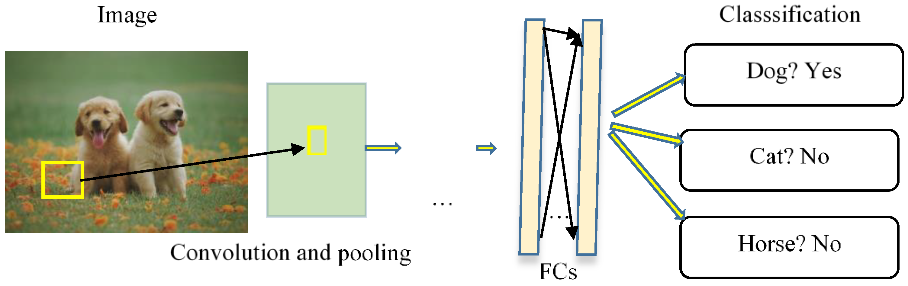
2.2.1. Convolutional Neural Networks (CNNs)
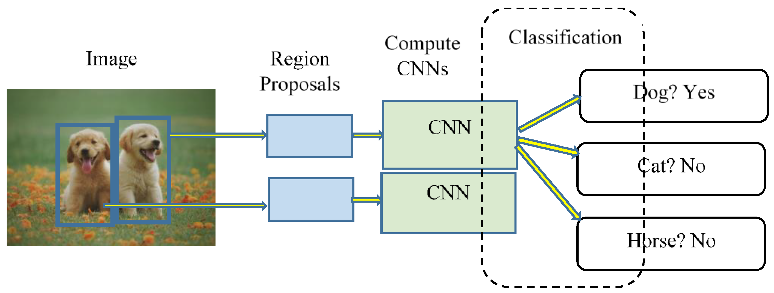
2.2.2. Proposed Region-Convolutional Neural Networks (R-CNNs)
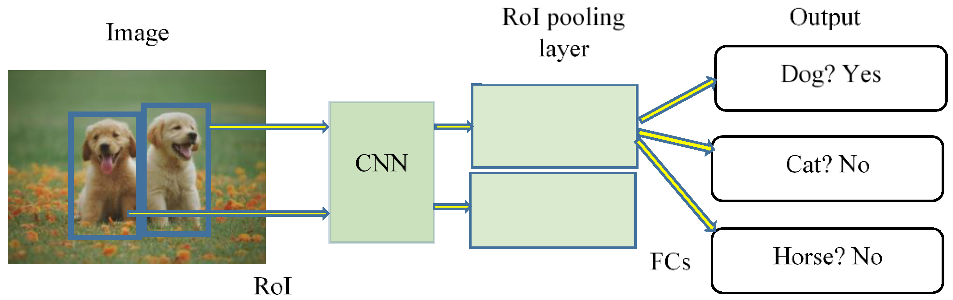
2.2.3. Fast Proposed Region-Convolutional Neural Networks (Fast R-CNNs)
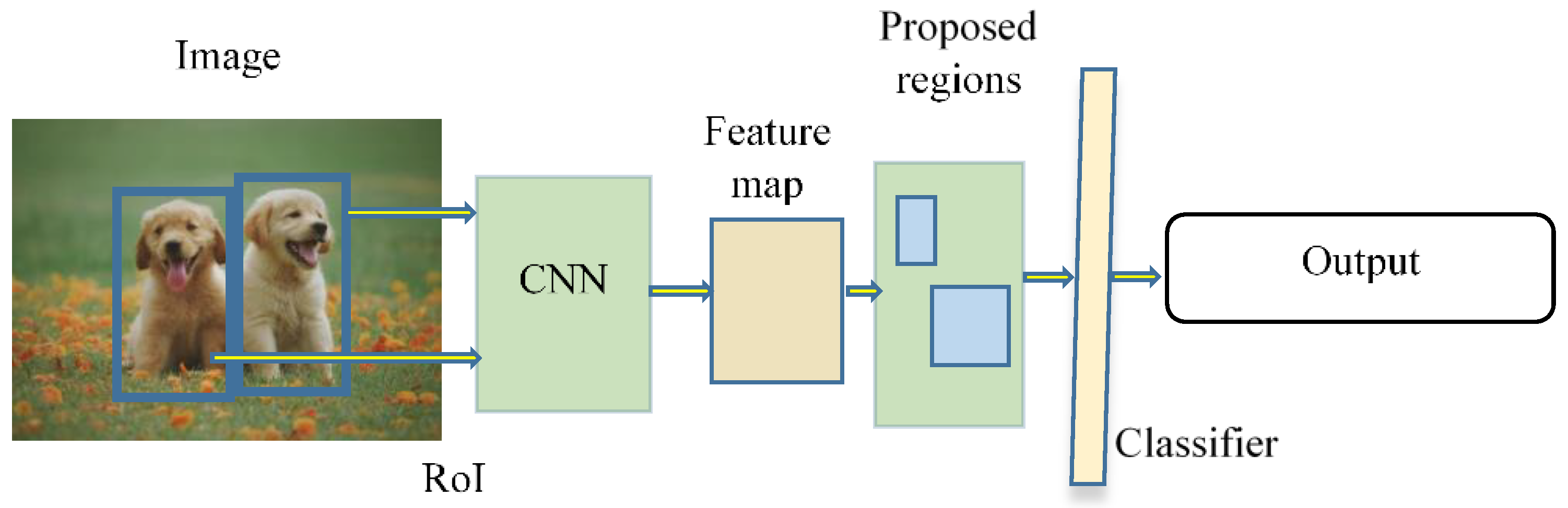
2.2.4. Faster Proposed Region-Convolutional Neural Networks (Faster R-CNNs)
2.3. Bayesian Model Development
3. Proposed Methodology and Experimentation
| Algorithm 1: ODCA for a robot pick and place operation operating on DL |
| start the robot operation; Collect robot joint data by get_data to help plan robot motion; if robot at home position then initialize the variables else move to the home position then initialize the variables end Update the image data with get_image_data; if the class matches with the image then pick and place the part from the memory location else stay at home position Update the location in memory; end |
4. Latency in the CPS
| Algorithm 2: Algorithm that is used for data collection for the sampling and resampling algorithm to study latency in a CPS |
| start the time; if algorithm 1 is running; while true: Collect activation time (x1) Collect the detection time (x2) Calculate the Total elapsed time (y) break end print x1, x2, and y end |
- Generate samples from the prior distribution, . The samples are denoted as .
- Compute the likelihood of observing the available data for each as .
- Compute a weight corresponding to each as .
- Generate samples of according to their weights .
5. Conclusions
Author Contributions
Funding
Data Availability Statement
Conflicts of Interest
References
- Lasi, H.; Fettke, P.; Kemper, H.-G.; Feld, T.; Hoffmann, M. Industry 4.0. Bus. Inf. Syst. Eng. 2014, 6, 239–242. [Google Scholar] [CrossRef]
- Rüßmann, M.; Lorenz, M.; Gerbert, P.; Waldner, M.; Engel, P.; Harnisch, M.; Justus, J. Future of Productivity and Growth in Manufacturing. Boston Consulting. 2015. Available online: https://scholar.google.com/scholar?hl=en&as_sdt=0%2C44&q=Future+of+Productivity+and+Growth+in+Manufacturing+boston+consulting&btnG=&oq=Future+of+Productivity+and+Growth+in+Manufacturing+boston+consult#d=gs_cit&t=1667019003402&u=%2Fscholar%3Fq%3Dinfo%3Ak1ZrpaIBKXQJ%3Ascholar.google.com%2F%26output%3Dcite%26scirp%3D0%26hl%3Den (accessed on 20 November 2019).
- Almada-Lobo, F. The Industry 4.0 revolution and the future of Manufacturing Execution Systems (MES). J. Innov. Manag. 2015, 3, 16–21. [Google Scholar] [CrossRef]
- Lee, J.; Kao, H.-A.; Yang, S. Service Innovation and Smart Analytics for Industry 4.0 and Big Data Environment. Procedia CIRP 2014, 16, 3–8. [Google Scholar] [CrossRef] [Green Version]
- Jamwal, A.; Agrawal, R.; Sharma, M.; Giallanza, A. Industry 4.0 Technologies for Manufacturing Sustainability: A Systematic Review and Future Research Directions. Appl. Sci. 2021, 11, 5725. [Google Scholar] [CrossRef]
- Jamwal, A.; Agrawal, R.; Sharma, M.; Kumar, V.; Kumar, S. Developing A sustainability framework for Industry 4.0. Procedia CIRP 2021, 98, 430–435. [Google Scholar] [CrossRef]
- Bai, C.; Dallasega, P.; Orzes, G.; Sarkis, J. Industry 4.0 technologies assessment: A sustainability perspective. Int. J. Prod. Econ. 2020, 229, 107776. [Google Scholar] [CrossRef]
- Vaidya, S.; Ambad, P.; Bhosle, S. Industry 4.0—A Glimpse. Procedia Manuf. 2018, 20, 233–238. [Google Scholar] [CrossRef]
- Pivoto, D.G.S.; de Almeida, L.F.F.; Da Rosa Righi, R.; Rodrigues, J.J.P.C.; Lugli, A.B.; Alberti, A.M. Cyber-physical systems architectures for industrial internet of things applications in Industry 4.0: A literature review. J. Manuf. Syst. 2021, 58, 176–192. [Google Scholar] [CrossRef]
- Jamwal, A.; Agrawal, R.; Manupati, V.K.; Sharma, M.; Varela, L.; Machado, J. Development of cyber physical system based manufacturing system design for process optimization. IOP Conf. Series: Mater. Sci. Eng. 2020, 997, 012048. [Google Scholar] [CrossRef]
- Nannapaneni, S.; Mahadevan, S.; Dubey, A.; Lee, Y.-T.T. Online monitoring and control of a cyber-physical manufacturing process under uncertainty. J. Intell. Manuf. 2021, 32, 1289–1304. [Google Scholar] [CrossRef]
- Kevin, A. That ’ Internet of Things’ Thing. RFiD J. 2010, 22, 4986. [Google Scholar]
- Lee, E.A. Cyber Physical Systems: Design Challenges. In Proceedings of the 11th IEEE International Symposium on Object and Component-Oriented Real-Time Distributed Computing (ISORC), Orlando, FL, USA, 5–7 May 2008; pp. 363–369. [Google Scholar]
- Radanliev, P.; De Roure, D.; Nicolescu, R.; Huth, M.; Santos, O. Artificial Intelligence and the Internet of Things in Industry 4.0. CCF Trans. Pervasive Comput. Interact. 2021, 3, 329–338. [Google Scholar] [CrossRef]
- Mazumder, S.K.; Kulkarni, A.; Sahoo, S.; Blaabjerg, F.; Mantooth, H.A.; Balda, J.C.; Zhao, Y.; Ramos-Ruiz, J.A.; Enjeti, P.N.; Kumar, P.R.; et al. A Review of Current Research Trends in Power-Electronic Innovations in Cyber–Physical Systems. IEEE J. Emerg. Sel. Top. Power Electron. 2021, 9, 5146–5163. [Google Scholar] [CrossRef]
- Wolf, W.; Tech, G. Cyber-Physical Systems. Impact Control. Technol. 2009, 12, 88–89. [Google Scholar] [CrossRef]
- Zupančič, J.; Bajd, T. Comparison of position repeatability of a human operator and an industrial manipulating robot. Comput. Biol. Med. 1998, 28, 415–421. [Google Scholar] [CrossRef]
- Heyer, C. Human-robot interaction and future industrial robotics applications. In Proceedings of the 2010 IEEE/RSJ International Conference on Intelligent Robots and Systems, Taipei, Taiwan, 18–22 October 2010; pp. 4749–4754. [Google Scholar] [CrossRef]
- Alvarez-De-Los-Mozos, E.; Renteria, A. Collaborative Robots in e-waste Management. Procedia Manuf. 2017, 11, 55–62. [Google Scholar] [CrossRef] [Green Version]
- Luo, S. Dynamic scheduling for flexible job shop with new job insertions by deep reinforcement learning. Appl. Soft Comput. 2020, 91, 106208. [Google Scholar] [CrossRef]
- Zhong, R.Y.; Xu, X.; Klotz, E.; Newman, S.T. Intelligent Manufacturing in the Context of Industry 4.0: A Review. Engineering 2017, 3, 616–630. [Google Scholar] [CrossRef]
- Mahesh, B. Machine Learning Algorithms-A Review. Int. J. Sci. Res. 2018, 9, 381–386. [Google Scholar] [CrossRef]
- Ayodele, T. Types of Machine Learning Algorithms. In New Advances in Machine Learning; Zhang, Y., Ed.; IntechOpen: London, UK, 2010. [Google Scholar] [CrossRef]
- Weckman, G.R.; Ganduri, C.V.; Koonce, D.A. A neural network job-shop scheduler. J. Intell. Manuf. 2008, 19, 191–201. [Google Scholar] [CrossRef]
- Venieris, S.I.; Bouganis, C.-S. Latency-driven design for FPGA-based convolutional neural networks. In Proceedings of the 2017 27th International Conference on Field Programmable Logic and Applications (FPL), Ghent, Belgium, 4–8 September 2017. [Google Scholar] [CrossRef]
- Maru, V.; Nannapaneni, S.; Krishnan, K. Internet of Things Based Cyber-Physical System Framework for Real-Time Operations. In Proceedings of the 2020 IEEE 23rd International Symposium on Real-Time Distributed Computing (ISORC), Nashville, TN, USA, 19–21 May 2020. [Google Scholar]
- Ren, S.; He, K.; Girshick, R.; Sun, J. Faster R-CNN: Towards Real-Time Object Detection with Region Proposal Networks. IEEE Trans. Pattern Anal. Mach. Intell. 2017, 39, 1137–1149. [Google Scholar] [CrossRef] [PubMed] [Green Version]
- Universal Robots. Real-Time Data Exchange (RTDE) Guide-22229. Universal Robots: Support. Available online: https://www.universal-robots.com/how-tos-and-faqs/how-to/ur-how-tos/real-time-data-exchange-rtde-guide-22229/ (accessed on 5 May 2021).
- Cardoso, J.; Derler, P.; Eidson, J.C.; Lee, E. Network latency and packet delay variation in cyber-physical systems. In Proceedings of the 2011 IEEE Network Science Workshop, West Point, NY, USA, 22–24 June 2011; pp. 51–58. [Google Scholar] [CrossRef] [Green Version]
- Delange, J.; Feiler, P. Incremental Latency Analysis of Heterogeneous Cyber-Physical Systems. In Proceedings of theThird International Workshop on Real-time and Distributed Computing in Emerging Applications, Rome, Italy, 2 December 2014; pp. 21–27. [Google Scholar]
- Zhu, Y.; Dong, Y.; Ma, C.; Zhang, F. A Methodology of Model-Based Testing for AADL Flow Latency in CPS. In Proceedings of the 2011 Fifth International Conference on Secure Software Integration and Reliability Improvement-Companion, Jeju, Korea, 27–29 June 2011; pp. 99–105. [Google Scholar] [CrossRef]
- Oliver, R.S.; Fohler, G. Probabilistic estimation of end-to-end path latency in Wireless Sensor Networks. In Proceedings of the 2009 IEEE 6th International Conference on Mobile Adhoc and Sensor Systems, Macau, China, 12–15 October 2009; pp. 423–431. [Google Scholar] [CrossRef]
- Claypool, M.; Finkel, D. The effects of latency on player performance in cloud-based games. In Proceedings of the 2014 13th Annual Workshop on Network and Systems Support for Games, Nagoya, Japan, 4–5 December 2014; pp. 1–6. [Google Scholar] [CrossRef]
- Van Trees, H.L.; Bell, K.L. A Tutorial on Particle Filters for Online Nonlinear/NonGaussian Bayesian Tracking. In Bayesian Bounds for Parameter Estimation and Nonlinear Filtering/Tracking; John Wiley: New York, NY, USA, 2007; pp. 10–1109. [Google Scholar] [CrossRef] [Green Version]
- Derler, P.; Lee, E.A.; Vincentelli, A.S. Modeling Cyber–Physical Systems. Proc. IEEE 2011, 100, 13–28. [Google Scholar] [CrossRef]
- Mörth, O.; Emmanouilidis, C.; Hafner, N.; Schadler, M. Cyber-physical systems for performance monitoring in production intralogistics. Comput. Ind. Eng. 2020, 142, 106333. [Google Scholar] [CrossRef]
- Saufi, S.R.; Bin Ahmad, Z.A.; Leong, M.S.; Lim, M.H. Challenges and Opportunities of Deep Learning Models for Machinery Fault Detection and Diagnosis: A Review. IEEE Access 2019, 7, 122644–122662. [Google Scholar] [CrossRef]
- Müller, J.M.; Kiel, D.; Voigt, K.-I. What Drives the Implementation of Industry 4.0? The Role of Opportunities and Challenges in the Context of Sustainability. Sustainability 2018, 10, 247. [Google Scholar] [CrossRef] [Green Version]
- Jamwal, A.; Agrawal, R.; Sharma, M.; Kumar, A.; Kumar, V.; Garza-Reyes, J.A.A. Machine learning applications for sustainable manufacturing: A bibliometric-based review for future research. J. Enterp. Inf. Manag. 2021, 35, 566–596. [Google Scholar] [CrossRef]
- Miskuf, M.; Zolotova, I. Comparison between Multi-Class Classifiers and Deep Learning with Focus on Industry 4.0. In Proceedings of the 2016 Cybernetics and Informatics, K and I 2016-Proceedings of the 28th International Conference, IEEE, Levoca, Slovakia, 2–5 February 2014; pp. 1–5. [Google Scholar] [CrossRef]
- Beaupre, M. Collaborative robot technology and applications. International Collaborative Robots Workshop. 2014, p. 41. Available online: https://www.robotics.org/userAssets/riaUploads/file/4-KUKA_Beaupre.pdf (accessed on 20 October 2022).
- Dumonteil, G.; Manfredi, G.; Devy, M.; Confetti, A.; Sidobre, D. Reactive Planning on a Collaborative Robot for Industrial Applications. In Proceedings of the 2015 12th International Conference on Informatics in Control, Automation and Robotics (ICINCO), Colmar, France, 21–23 July 2015; pp. 450–457. [Google Scholar] [CrossRef] [Green Version]
- Brandstötter, M.; Komenda, T.; Ranz, F.; Wedenig, P.; Gattringer, H.; Kaiser, L.; Breitenhuber, G.; Schlotzhauer, A.; Müller, A.; Hofbaur, M. Versatile Collaborative Robot Applications Through Safety-Rated Modification Limits. Adv. Intell. Syst. Comput. 2020, 980, 438–446. [Google Scholar] [CrossRef]
- Biggs, G.; Macdonald, B. A Survey of Robot Programming Systems. In Proceedings of the Australasian Conference on Robotics and Automation; 2003; pp. 1–3. [Google Scholar]
- El-Zorkany, H. Robot Programming. INFOR: Inf. Syst. Oper. Res. 1985, 23, 430–446. [Google Scholar] [CrossRef]
- Zhou, Z.; Xiong, R.; Wang, Y.; Zhang, J. Advanced Robot Programming: A Review. Curr. Robot. Rep. 2020, 1, 251–258. [Google Scholar] [CrossRef]
- Abadi, M.; Barham, P.; Chen, J.; Chen, Z.; Davis, A.; Dean, J.; Devin, M.; Ghemawat, S.; Irving, G.; Isard, M.; et al. TensorFlow: A System for Large-Scale Machine Learning. Proceedings of the 12th USENIX Symposium on Operating Systems Design and Implementation. OSDI 2016, 2016, 265–283. [Google Scholar] [CrossRef]
- François, C. Keras: The Python Deep Learning Library; Astrophysics source code library, 2015; ascl:1806.022; Available online: https://ascl.net/1806.022 (accessed on 20 November 2019).
- Lecun, Y.; Bottou, L.; Bengio, Y.; Haffner, P. Gradient-based learning applied to document recognition. Proc. IEEE 1998, 86, 2278–2324. [Google Scholar] [CrossRef]
- Girshick, R.; Donahue, J.; Darrell, T.; Malik, J. Rich feature hierarchies for accurate object detection and semantic segmentation. In Proceedings of the IEEE Conference on Computer Vision and Pattern Recognition, Columbus, OH, USA, 23–28 June 2014; pp. 580–587. [Google Scholar] [CrossRef] [Green Version]
- Girshick, R. Fast R-CNN. In Proceedings of the 2015 IEEE International Conference on Computer Vision (ICCV), Santiago, Chile, 7–13 December 2015; pp. 1440–1448. [Google Scholar] [CrossRef]
- Krizhevsky, A.; Sutskever, I.; Hinton, G.E. Imagenet classification with deep convolutional neural networks. NIPS 2017, 60, 84–90. [Google Scholar] [CrossRef] [Green Version]
- Gkioxari, G.; Girshick, R.; Malik, J. Contextual Action Recognition with R CNN. In Proceedings of the IEEE international conference on computer vision, Santiago, Chile, 7–13 December 2015; 2015; pp. 1080–1088. [Google Scholar] [CrossRef] [Green Version]
- Smith, A.F.M.; Gelfand, A.E. Bayesian Statistics without Tears: A Sampling–Resampling Perspective. Am. Stat. 1992, 46, 84–88. [Google Scholar] [CrossRef]
- Lin, T.Y.; Maire, M.; Belongie, S.; Bourdev, L.; Girshick, R.; Hays, J.; Perona, P.; Zitnick, C.L.; Dollár, P. Microsoft COCO: Common Objects in Context. Available online: https://cocodataset.org/ (accessed on 20 November 2019).
- Mandic, D.P. Descent Algorithm. Signal Processing 2004, 11, 115–118. [Google Scholar]
- Cauchy, M.A. Méthode Générale Pour La Résolution Des Systèmes d’équations Simultanées. C R Hebd Seances Acad. Sci. 1847, 25, 536–538. [Google Scholar]
- Xue, M.; Zhu, C. The Socket Programming and Software Design for Communication Based on Client/Server. In Proceedings of the 2009 Pacific-Asia Conference on Circuits, Communications and Systems, Chengdu, China, 16–17 May 2009; pp. 775–777. [Google Scholar] [CrossRef]
- Espinosa, F.; Salazar, M.; Valdes, F.; Bocos, A. Communication architecture based on Player/Stage and sockets for cooperative guidance of robotic units. In Proceedings of the 2008 16th Mediterranean Conference on Control and Automation, Ajaccio, France, 25–27 June 2008; pp. 1423–1428. [Google Scholar] [CrossRef]
- Bengio, Y.; LeCun, Y. Scaling learning algorithms towards AI. Large-Scale Kernel Mach. 2007, 34, 1–41. [Google Scholar]
- Terrell, G.R.; Scott, D.W. Variable Kernel Density Estimation. Ann. Stat. 1992, 20, 1236–1265. [Google Scholar] [CrossRef]


| # | |||
|---|---|---|---|
| 1 | 1.56 | 24.38 | 26.38 |
| 2 | 2.13 | 24.45 | 27.03 |
| 3 | 1.57 | 24.10 | 26.14 |
| 4 | 2.25 | 24.46 | 27.18 |
| 5 | 1.53 | 25.06 | 27.13 |
| 6 | 2.10 | 24.19 | 26.43 |
| 7 | 2.07 | 24.16 | 26.28 |
| 8 | 2.07 | 24.43 | 26.56 |
| 9 | 1.58 | 24.08 | 26.19 |
| 10 | 2.06 | 24.16 | 26.26 |
| 11 | 2.02 | 24.22 | 26.27 |
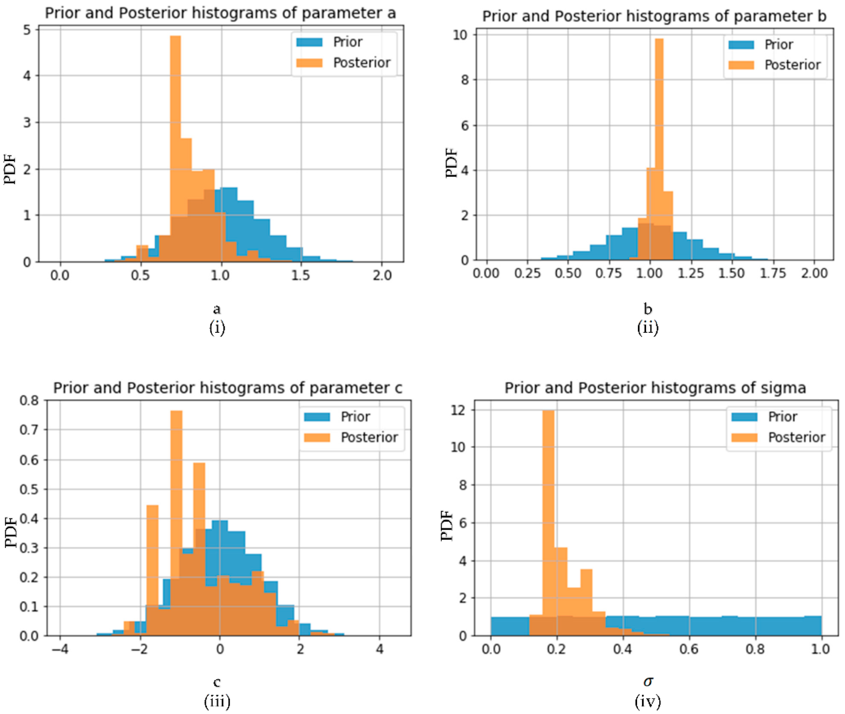
| Mean | Standard Deviation | ||
|---|---|---|---|
| Prior | 1 | 0.25 | |
| Posterior | 0.689 | 0.208 | |
| Prior | 1 | 0.25 | |
| Posterior | 1.038 | 0.038 | |
| Prior | 0 | 1 | |
| Posterior | −0.062 | 0.906 | |
| Prior | 0.5 | 0.289 | |
| Posterior | 0.207 | 0.067 |
Publisher’s Note: MDPI stays neutral with regard to jurisdictional claims in published maps and institutional affiliations. |
© 2022 by the authors. Licensee MDPI, Basel, Switzerland. This article is an open access article distributed under the terms and conditions of the Creative Commons Attribution (CC BY) license (https://creativecommons.org/licenses/by/4.0/).
Share and Cite
Maru, V.; Nannapaneni, S.; Krishnan, K.; Arishi, A. Deep-Learning-Based Cyber-Physical System Framework for Real-Time Industrial Operations. Machines 2022, 10, 1001. https://doi.org/10.3390/machines10111001
Maru V, Nannapaneni S, Krishnan K, Arishi A. Deep-Learning-Based Cyber-Physical System Framework for Real-Time Industrial Operations. Machines. 2022; 10(11):1001. https://doi.org/10.3390/machines10111001
Chicago/Turabian StyleMaru, Vatsal, Saideep Nannapaneni, Krishna Krishnan, and Ali Arishi. 2022. "Deep-Learning-Based Cyber-Physical System Framework for Real-Time Industrial Operations" Machines 10, no. 11: 1001. https://doi.org/10.3390/machines10111001