
Dynamics Modelling and Control of a Novel Fuel Metering Valve Actuated by Two Binary-Coded Digital Valve Arrays


Abstract
:1. Introduction
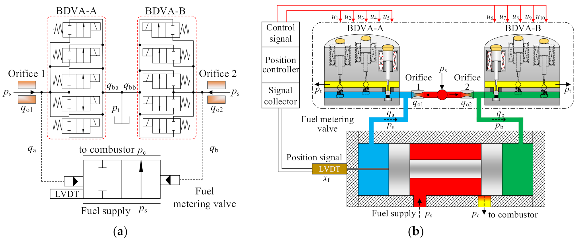
2. Structure and Working Principle
3. Mathematical Model of the Fuel Metering Valve
3.1. Binary-Coded Digital Valve Array
- (1)
- Static flow model of the BDVA
- (2)
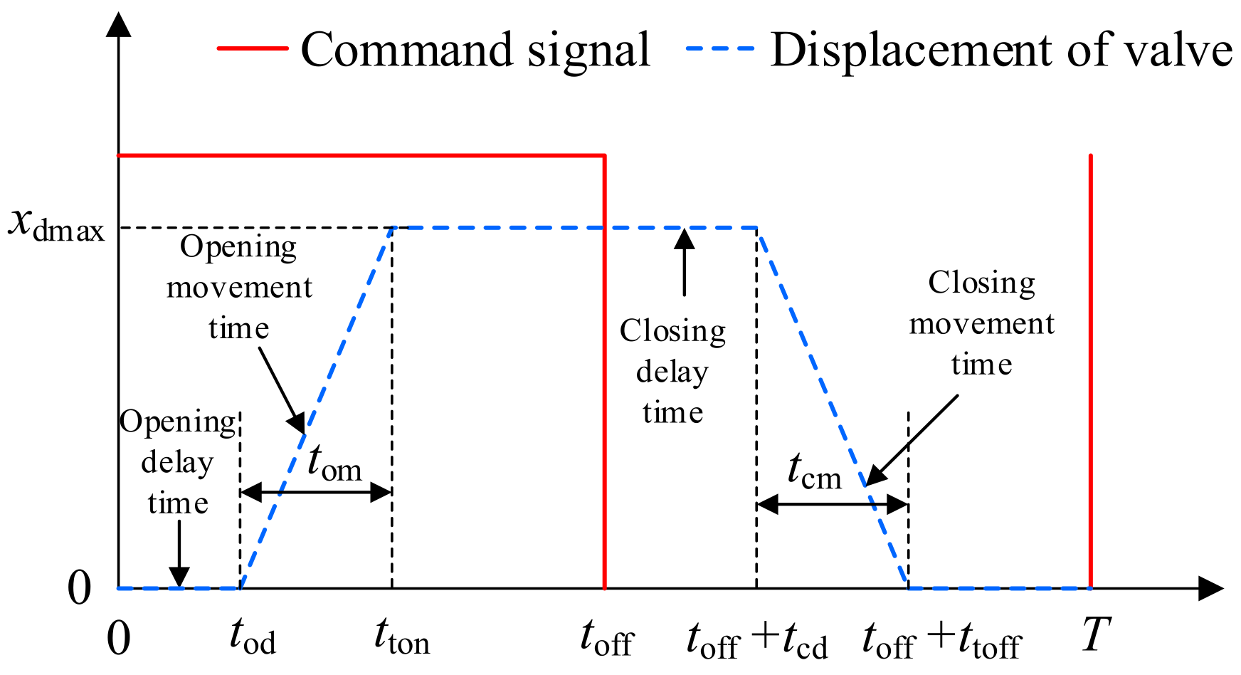
- Dynamic model of the BDVA
3.2. Flow Model of the Pilot Stage
3.3. Dynamic Model of the Fuel Metering Valve
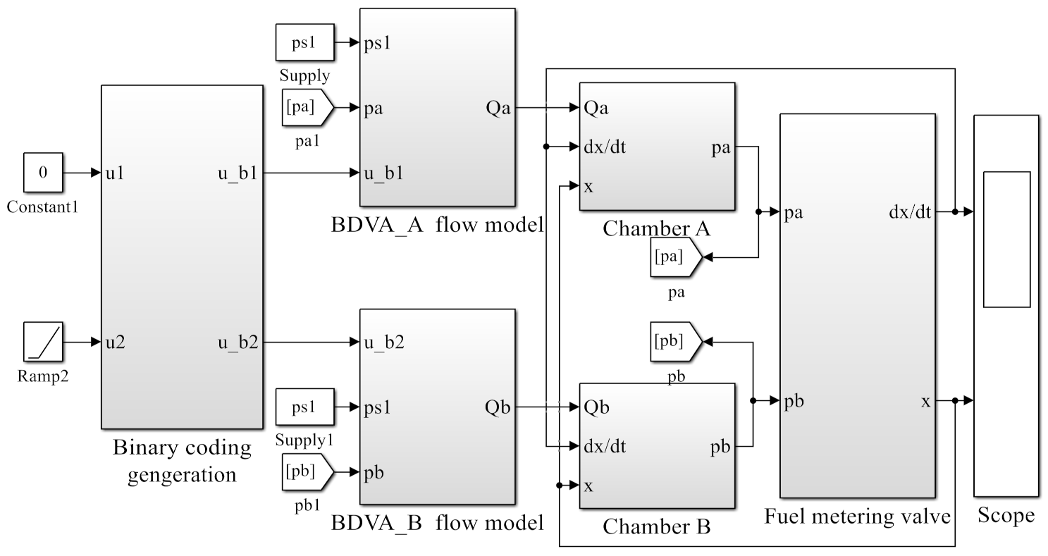
3.4. Simulation Model and Parameters
4. Dynamic Characteristics of the Fuel Metering Valve
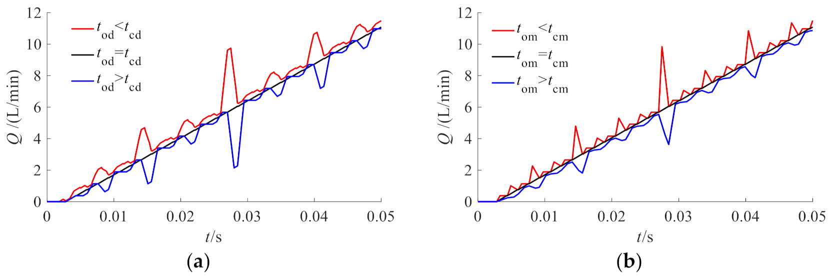
4.1. Transient Flow Uncertainty of the BDVA
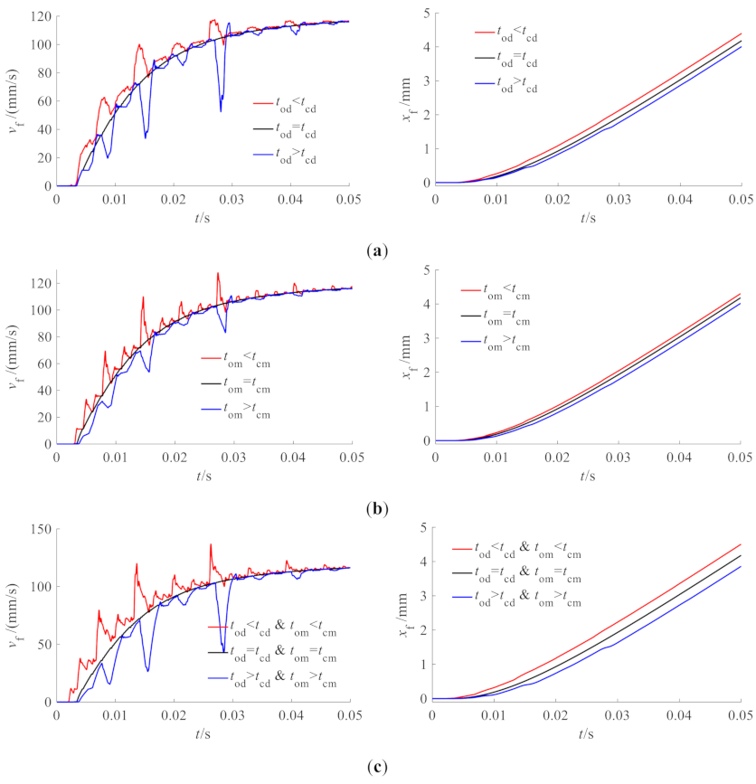
4.2. Effects of the Transient Flow Uncertainty of BDVA on the Movement Fuel Metering Valve
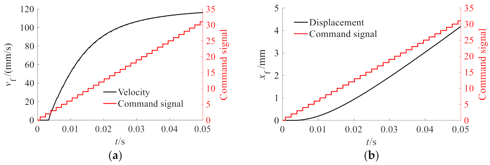
4.3. Step Response of the Fuel Metering Valve
5. Position Controller of the Fuel Metering Valve
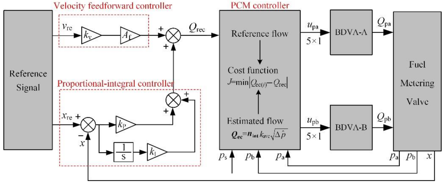
5.1. Design of the Position Controller
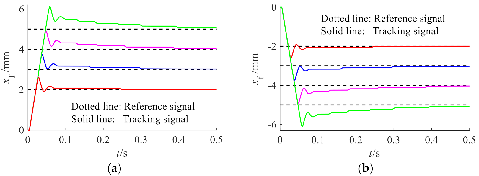
5.2. Validation of the Position Controller
6. Conclusions
- (1)
- The structure and working principle of the proposed fuel metering valve were discussed. In addition, the mathematical model was established, including the pilot flow model of the BDVA and dynamic model of the metering spool. Subsequently, a simulation model of the entire valve system was developed using MATLAB/Simulink.
- (2)
- The mechanism of the transient flow uncertainty of the pilot BDVA was revealed through simulation. The BDVA produces transient flow with uncertainty due to the unsynchronized opening and closing of the on–off valves, but when used in the pilot stage, it has little effect on the movement of the main stage.
- (3)
- Simulation results of the position step response indicated that the delay time of the fuel metering valve under different reference step signals was within 4.1 ms. In addition, the maximum overshoot and maximum steady error were 1.10 and 0.074 mm, respectively.
- (4)
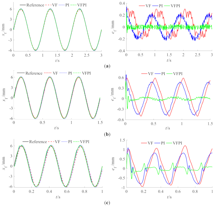
- To improve the position tracking accuracy of the fuel metering valve, a velocity feedforward proportional-integral control strategy (VFPI) with PCM coding was proposed. A comparison between the controllers demonstrated that the average and standard deviation of the position tracking error under the proposed VFPI controller were reduced by 78 and 72.7%, respectively.
- (5)
- The proposed pilot structure consisting of two binary-coded digital valve arrays can be used not only for the pilot stage of fuel metering valves in this research, but also for the pilot stage of proportional/servo valves with large flow rate to improve reliability and digitization.
Author Contributions
Funding
Institutional Review Board Statement
Informed Consent Statement
Data Availability Statement
Conflicts of Interest
References
- Wang, B.; Zhao, H.C.; Ye, Z.F. AMESim simulation of afterburning metering unit for fuel system. Aeroengine 2014, 40, 62–66. [Google Scholar]
- Cai, J.; Hu, W.; Cai, K.Y. Accuracy analysis of a single-fault Markov model for FADEC system. J. Syst. Eng. Ecletronics 2019, 30, 1044–1052. [Google Scholar]
- Hang, J.; Li, Y.; Yang, L.; Li, Y. Design and simulation of large flowrate fuel metering valve of aero engine based on AMESim. In Proceedings of the 15th IEEE Conference on Industrial Electronics and Applications (ICIEA), Kristiansand, Norway, 9–13 November 2020; pp. 1932–1937. [Google Scholar]
- Yuan, Y.; Zhang, T.; Lin, Z.; Zhang, J. An investigation into factors determining the metering performance of a fuel control unit in an aero engine. Flow Meas. Instrum. 2020, 71, 1–6. [Google Scholar] [CrossRef]
- Ao, L.Z. Faults detection logic updating of fuel metering valve on aero-engine. Adv. Mater. Res. 2012, 503, 1660–1663. [Google Scholar] [CrossRef]
- Bertin, M.; Plummer, A.; Bowen, C.; Johnston, N.; Griffiths, M.; Bickley, D. A dual lane piezoelectric ring bender actuated nozzle-flapper servo valve for aero engine fuel metering. Smart Mater. Struct. 2019, 28, 115015. [Google Scholar] [CrossRef]
- Wang, B.; Zhao, H.C.; Yu, L.; Ye, Z.F. Study of temperature effect on servovalve-controlled fuel metering unit. ASME. J. Eng. Gas Turbines Power. 2015, 137, 061503. [Google Scholar] [CrossRef]
- Yang, C.; Huang, Q.; Jiang, H.; Peter, O.O.; Han, J. PD control with gravity compensation for hydraulic 6-DOF parallel manipulator. Mech. Mach. Theory 2010, 45, 666–677. [Google Scholar] [CrossRef]
- Zhang, Y.; Wang, S.P.; Shi, J.; Wang, X. Evaluation of thermal effects on temperature sensitive operating force of flow servo valve for fuel metering unit. Chin. J. Aeronaut. 2020, 33, 1812–1823. [Google Scholar] [CrossRef]
- Ma, L.; Yan, H.; Cai, C.; Ren, Y. Mechanism of temperature-induced zero drift on electro-hydraulic servo valve. AIP Adv. 2021, 11, 065210. [Google Scholar] [CrossRef]
- Yan, H.; Liu, Y.; Ma, L. Mechanism of temperature’s acting on electro-hydraulic servo valve. IEEE Access 2019, 7, 80465–80477. [Google Scholar] [CrossRef]
- Wang, Y.; Yin, Y. Performance reliability of jet pipe servo valve under random vibration environment. Mechatronics 2019, 64, 102286. [Google Scholar] [CrossRef]
- Cardozo, W.S.; Weber, H.I. Dynamic modeling of a 2-dof parallel electrohydraulic-actuated homokinetic platform. Mech. Mach. Theory 2017, 118, 1–13. [Google Scholar] [CrossRef]
- Tang, W.; Xu, G.; Zhang, S.; Jin, S.; Wang, R. Digital Twin-Driven Mating Performance Analysis for Precision Spool Valve. Machines 2021, 9, 157. [Google Scholar] [CrossRef]
- Wu, S.; Zhao, X.Y.; Li, C.F.; Jiao, Z.; Qu, F. Multi-objective optimization of a hollow plunger type solenoid for high speed on/off valve. IEEE Trans. Ind. Electron. 2018, 65, 3115–3124. [Google Scholar] [CrossRef]
- Wang, S.; Zhang, B.; Zhong, Q.; Yang, H. Study on control performance of pilot high-speed switching valve. Adv. Mech. Eng. 2017, 9, 664–671. [Google Scholar] [CrossRef] [Green Version]
- Xiong, X.Y.; Huang, J.H. Performance of a flow control valve with pilot switching valve. Proc. Inst. Mech. Eng. Part I J. Syst. Control Eng. 2018, 232, 178–194. [Google Scholar] [CrossRef]
- Tamburrano, P.; Plummer, A.; Palma, P.; Distaso, E.; Amirantel, R. A novel servo valve pilot stage actuated by a piezoelectric ring bender (Part II): Design Model and Full Simulation. Energies 2020, 13, 2267. [Google Scholar] [CrossRef]
- Gao, Q.; Zhu, Y.; Wu, C.; Jiang, Y. Development of a novel two-stage proportional valve with a pilot digital flow distribution. Front. Mech. Eng. 2021, 16, 420–434. [Google Scholar] [CrossRef]
- Zhu, Y.; Li, G.; Wang, R.; Tang, S.; Su, H.; Cao, K. Intelligent fault diagnosis of hydraulic piston pump combining improved lenet-5 and PSO hyperparameter optimization. Appl. Acoust. 2021, 183, 108336. [Google Scholar] [CrossRef]
- Laamanen, M.S.A.; Vilenius, M. Is it time for digital hydraulics. In Proceedings of the eighth Scandinavian international conference on fluid power, Tampere, Finland, 7–9 May 2003; Tampere University of Technology: Tampere, Finland. [Google Scholar]
- Linjama, M. Digital fluid power: State of the art. In Proceedings of the Twelfth Scandinavian International Conference on Fluid Power, Tampere, Finland, 18–20 May 2011; Tampere University of Technology: Tampere, Finland. [Google Scholar]
- Paloniitty, M.; Linjama, M. High-linear digital hydraulic valve control by an equal coded valve system and novel switching schemes. Proc IMechE Part I J Syst. Control Eng. 2018, 232, 258–269. [Google Scholar] [CrossRef]
- Gao, Q.; Linjama, M.; Paloniitty, M.; Zhu, Y.C. Investigation on positioning control strategy and switching optimization of an equal coded digital valve system. Proc IMechE Part I J Syst. Control Eng. 2020, 234, 959–972. [Google Scholar] [CrossRef]
- Sun, D.; Jiao, Z.X.; Shang, Y.X. High-efficiency aircraft antiskid brake control algorithm via runway condition identification based on an on-off valve array. Chin. J. Aeronaut. 2019, 32, 2538–2556. [Google Scholar] [CrossRef]
- Heikkilä, M.; Linjama, M. Displacement control of a mobile crane using a digital hydraulic power management system. Mechatronics 2013, 23, 452–461. [Google Scholar] [CrossRef]
- Linjama, M.; Huova, M.; Huhtala, K. Model-based force and position tracking control of an asymmetric cylinder with a digital hydraulic valve. Int. J. Fluid Power 2016, 17, 163–172. [Google Scholar] [CrossRef]
- Linjama, M.; Huova, M. Model-based force and position tracking control of a multi-pressure hydraulic cylinder. Proc. Inst. Mech. Eng. Part I J. Syst. Control. Eng. 2018, 232, 324–335. [Google Scholar] [CrossRef]
- Lantela, T.; Pietola, M. High-flow rate miniature digital valve system. Int. J. Fluid Power 2017, 18, 188–195. [Google Scholar] [CrossRef]
- Gao, Q.; Zhu, Y.C.; Wu, C.W.; Jiang, Y. Identification of critical moving characteristics in high speed on/off valve based on time derivative of the coil current. Proc. Inst. Mech. Eng. Part I J. Syst. Control Eng. 2021, 235, 1084–1099. [Google Scholar] [CrossRef]
- Zhong, Q.; Wang, X.L.; Zhou H., Z.; Xie, G.; Hong, H.C.; Yan, Y.B.; Chen, B.; Yang, H.Y. Investigation into the adjustable dynamic characteristic of the high-speed on/off valve with an advanced pulsewidth modulation control algorithm. IEEE/ASME Trans. Mechatronics 2021, 1–14. [Google Scholar] [CrossRef]
- Mao, J.; Yang, L.; Hu, Y.; Liu, K.; Du, J. Research on Vehicle Adaptive Cruise Control Method Based on Fuzzy Model Predictive Control. Machines 2021, 9, 160. [Google Scholar] [CrossRef]
- Yao, J.Y.; Deng, W.X.; Jiao, Z.X. Adaptive control of hydraulic actuators with LuGre model-based friction compensation. IEEE Trans. Ind. Electron. 2015, 62, 6469–6477. [Google Scholar] [CrossRef]


| Dynamic Time | Valve 1 | Valve 2 | Valve 3 | Valve 4 | Valve 5 |
|---|---|---|---|---|---|
| Opening delay time | tod1 | tod2 | tod3 | tod4 | tod5 |
| Opening movement time | tom1 | tom2 | tom3 | tom4 | tom5 |
| Closing delay time | tcd1 | tcd2 | tcd3 | tcd4 | tcd5 |
| Closing movement time | tcm1 | tcm2 | tcm3 | tcm4 | tcm5 |
| Parameters | Variables | Value |
|---|---|---|
| Opening delay time | tod | 2 ms |
| Opening movement time | tom | 1.5 ms |
| Closing delay time | tcd | 2 ms |
| Closing movement time | tcm | 1.5 ms |
| Digital valve’s flow coefficient | Cd | 0.65 |
| Maximum opening area of the smallest valve | Admax | 0.128 mm2 |
| Main valve’s mass | m | 205 g |
| Viscous friction coefficient | Bf | 17.6 N/(m/s) |
| Initial volume of chamber | Vf | 3750 mm3 |
| Coulomb friction force | Fc | 6 N |
| Fixed orifice’s flow coefficient | Cf | 0.85 |
| Fluid jet angle | θ | 69° |
| Cross-sectional area | Af | 314 mm2 |
| Performance Indexes | Reference Step Signal (Positive Movement) | Reference Step Signal (Negative Movement) | ||||||
|---|---|---|---|---|---|---|---|---|
| 2 mm | 3 mm | 4 mm | 5 mm | –2 mm | –3 mm | –4 mm | –5 mm | |
| Delay time (ms) | 4.1 | 4.1 | 4.1 | 4.1 | 4.1 | 4.1 | 4.1 | 4.1 |
| Rising time (ms) | 19.8 | 27.3 | 35.1 | 42.8 | 19.8 | 27.3 | 35.1 | 42.8 |
| Overshoot (mm) | 0.61 | 0.74 | 0.91 | 1.10 | 0.61 | 0.74 | 0.91 | 1.10 |
| Steady error (mm) | 0 | 0.027 | 0.035 | 0.074 | 0 | 0.027 | 0.035 | 0.075 |
| Amplitudes | Frequency | Average Error μ (mm) | Standard Deviation of Tracking Error σ (mm) | ||||
|---|---|---|---|---|---|---|---|
| VF | PI | VFPI | VF | PI | VFPI | ||
| 4.5 mm | 1 Hz | 0.244 | 0.096 | 0.021 | 0.274 | 0.108 | 0.027 |
| ↓60.7% | ↓91.4% | ↓60.6% | ↓90.1% | ||||
| 2 Hz | 0.235 | 0.219 | 0.025 | 0.267 | 0.245 | 0.04 | |
| ↓6.8% | ↓89.4% | ↓8.2% | ↓85.0% | ||||
| 3 Hz | 0.343 | 0.345 | 0.058 | 0.398 | 0.389 | 0.089 | |
| ↑0.6% | ↓83.1% | ↓2.3% | ↓77.6% | ||||
| 6 mm | 1 Hz | 0.157 | 0.126 | 0.022 | 0.175 | 0.14 | 0.03 |
| ↓19.7% | ↓86.0% | ↓20% | ↓82.9% | ||||
| 2 Hz | 0.308 | 0.292 | 0.034 | 0.349 | 0.327 | 0.058 | |
| ↓5.2% | ↓89.0% | ↓6.3% | ↓83.4% | ||||
| 3 Hz | 0.558 | 0.493 | 0.123 | 0.649 | 0.57 | 0.177 | |
| ↓11.6% | ↓78.0% | ↓12.2% | ↓72.7% | ||||
Publisher’s Note: MDPI stays neutral with regard to jurisdictional claims in published maps and institutional affiliations. |
© 2022 by the authors. Licensee MDPI, Basel, Switzerland. This article is an open access article distributed under the terms and conditions of the Creative Commons Attribution (CC BY) license (https://creativecommons.org/licenses/by/4.0/).
Share and Cite
Gao, Q.; Zhu, Y.; Liu, J. Dynamics Modelling and Control of a Novel Fuel Metering Valve Actuated by Two Binary-Coded Digital Valve Arrays. Machines 2022, 10, 55. https://doi.org/10.3390/machines10010055
Gao Q, Zhu Y, Liu J. Dynamics Modelling and Control of a Novel Fuel Metering Valve Actuated by Two Binary-Coded Digital Valve Arrays. Machines. 2022; 10(1):55. https://doi.org/10.3390/machines10010055
Chicago/Turabian StyleGao, Qiang, Yong Zhu, and Jinhua Liu. 2022. "Dynamics Modelling and Control of a Novel Fuel Metering Valve Actuated by Two Binary-Coded Digital Valve Arrays" Machines 10, no. 1: 55. https://doi.org/10.3390/machines10010055