
Structural Damage Identification Using the First-Order Vibration-Mode-Based Frequency-Shift Flexibility Sensitivity Algorithm

Abstract
:1. Introduction
2. Theoretical Development
- (1)
- Establish the FEM of the intact structure to obtain the stiffness and mass matrices and .
- (2)
- Conduct dynamic analysis on the structure and measure the lower-order eigen-pairs of the intact and damaged structures.
- (3)
- Compute the flexibility change by Equation (8) and compute the elementary flexibility sensitivity matrix by Equation (13).
- (4)
- Compute the damage coefficients () by solving Equation (12). Finally, the damage locations and extents in the structure can be determined according to the values of ().
- (1)
- Establish the FEM of the intact structure to obtain the stiffness and mass matrices and .
- (2)
- Conduct dynamic analysis on the structure and measure the first-order eigen-pairs of the intact and damaged structures.
- (3)
- Compute the frequency-shift flexibility change by Equation (22) and compute the elementary frequency-shift flexibility sensitivity matrix by Equation (24).
- (4)
- Compute the damage coefficients () by solving Equation (23). Finally, the damage locations and extents in the structure can be determined according to the values of (). To resist the adverse effects of data noise due to measurement error, the singular-value truncation algorithm [31,32] is used in the process of solving the linear Equation (23) for achieving stable computational results in engineering applications. The core idea of the singular-value truncation algorithm is to ignore small singular values to partially eliminate the impact of data noise on the calculation results. The main formulas of the singular-value truncation algorithm are briefly illustrated as follows. Firstly, Equation (23) can be rewritten as a system of linear equations as:
3. Numerical Example
3.1. A Truss Structure
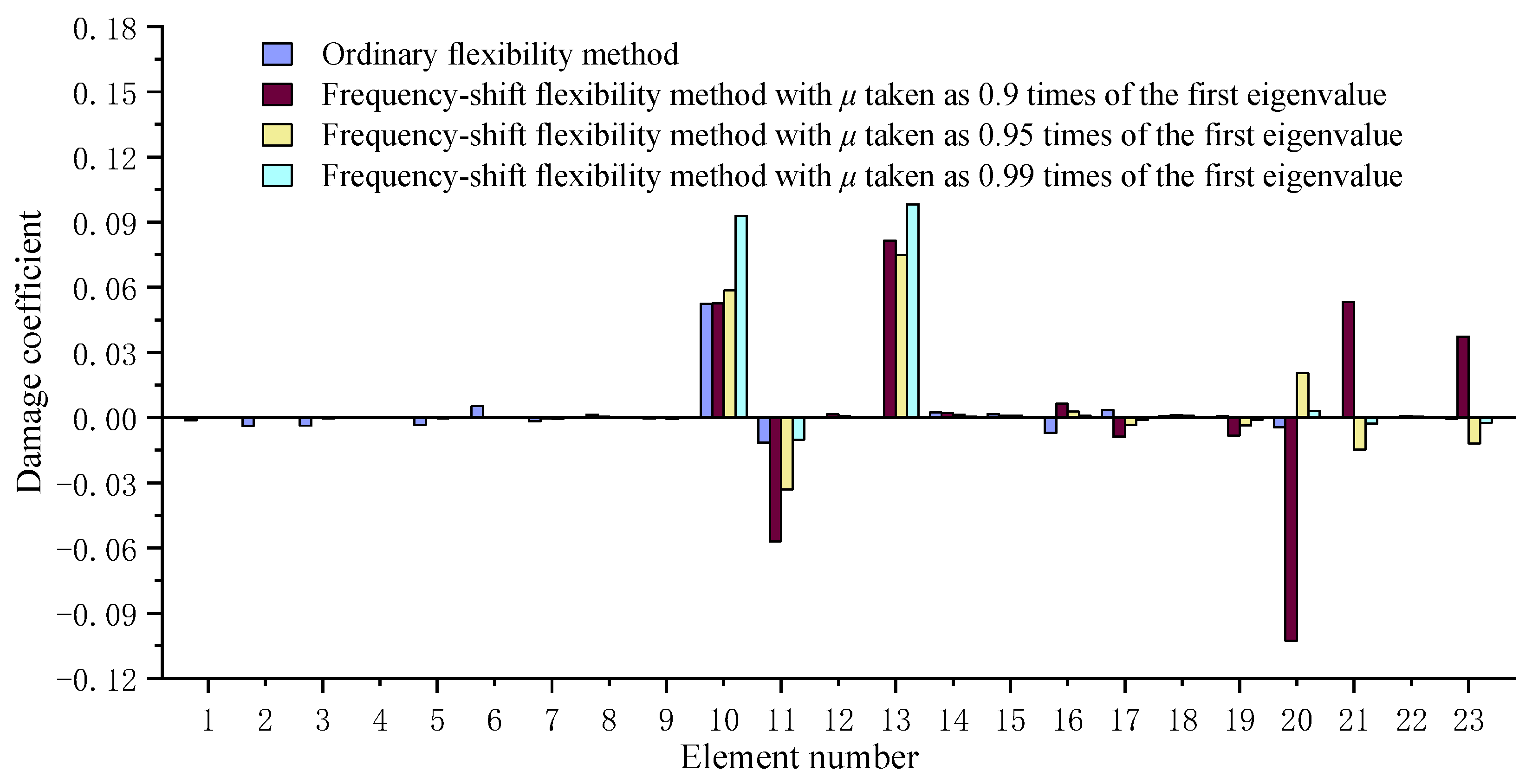
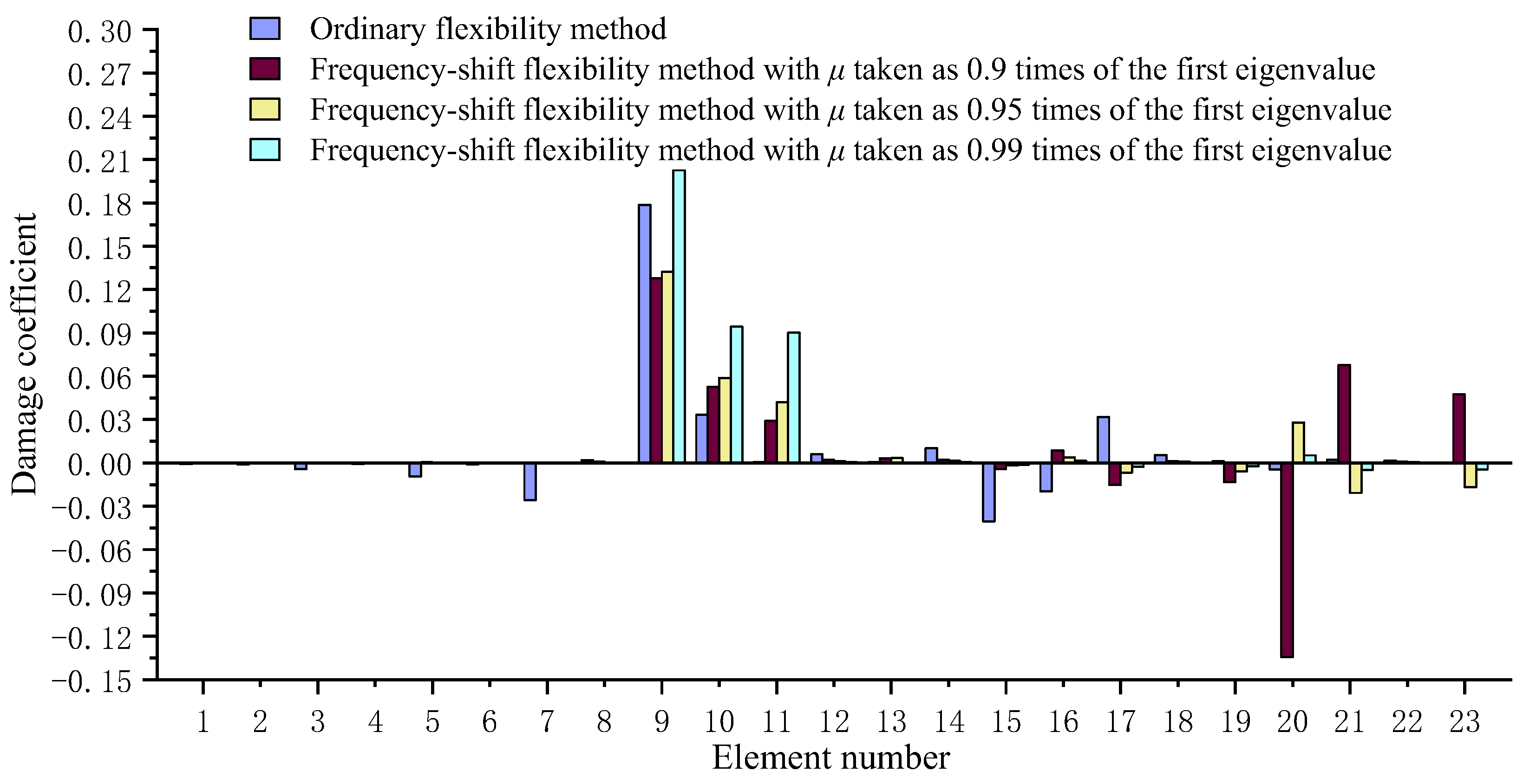
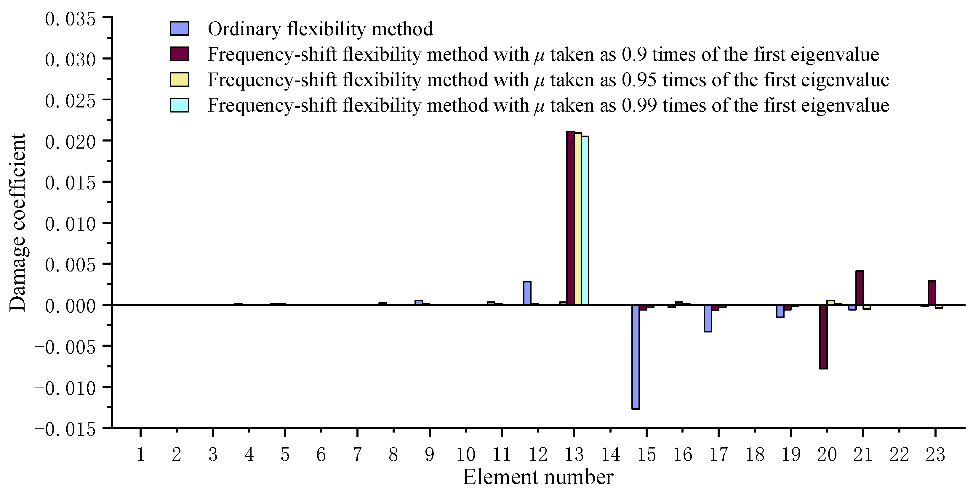
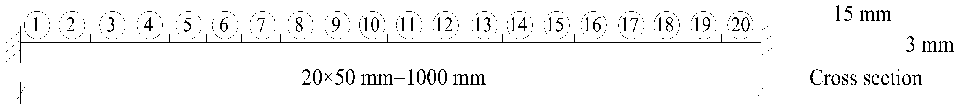
3.2. A Beam Structure
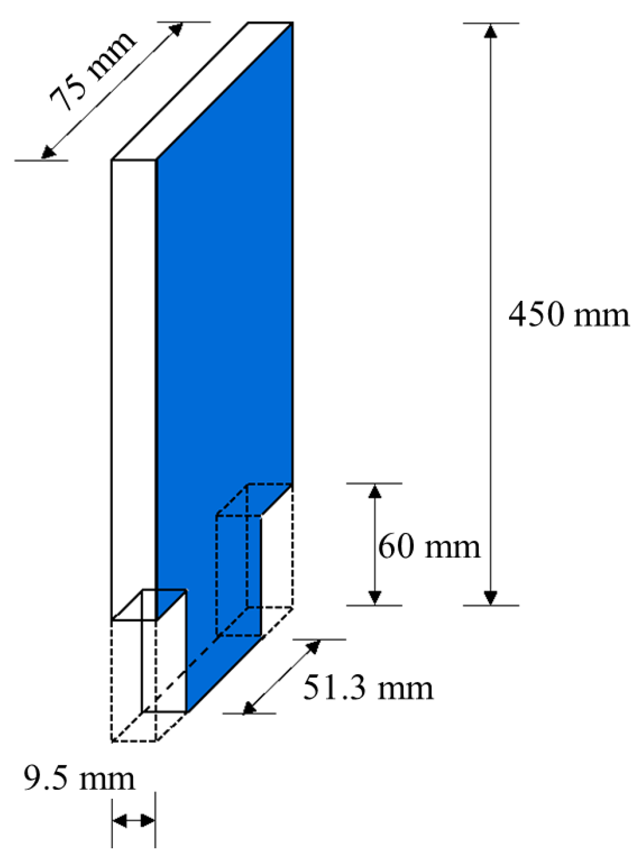
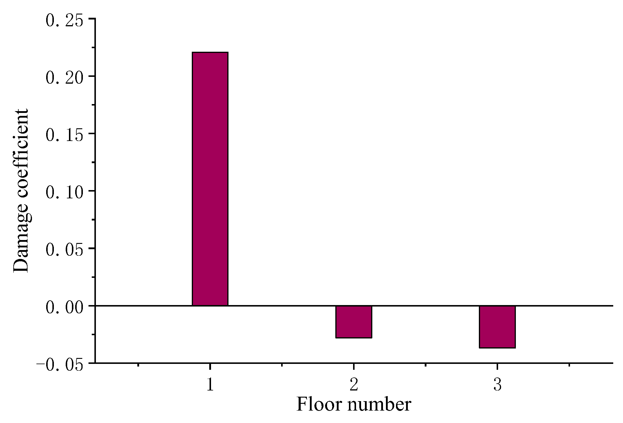
4. Validation by the Experimental Data of a Steel Frame Structure
5. Conclusions
Author Contributions
Funding
Data Availability Statement
Conflicts of Interest
References
- Torzoni, M.; Manzoni, A.; Mariani, S. A multi-fidelity surrogate model for structural health monitoring exploiting model order reduction and artificial neural networks. Mech. Syst. Signal Process. 2023, 197, 110376. [Google Scholar] [CrossRef]
- Peng, X.; Yang, Q.W. Damage detection in beam-like structures using static shear energy redistribution. Front. Struct. Civ. Eng. 2022, 16, 1552–1564. [Google Scholar] [CrossRef]
- Peng, X.; Tian, C.; Yang, Q. Structural Damage Identification Using the Optimal Achievable Displacement Variation. Materials 2022, 15, 8440. [Google Scholar] [CrossRef] [PubMed]
- Yang, Q.W.; Liu, J.K. Structural damage identification with flexibility changed: A review. J. Vib. Shock 2011, 30, 147–153. [Google Scholar]
- Pandey, A.K.; Biswas, M. Damage detection in structures using changes in flexibility. J. Sound Vib. 1994, 169, 3–17. [Google Scholar] [CrossRef]
- Jaishi, B.; Ren, W.X. Damage detection by finite element model updating using modal flexibility residual. J. Sound Vib. 2006, 290, 369–387. [Google Scholar] [CrossRef]
- Catbas, F.N.; Brown, D.L.; Aktan, A.E. Use of modal flexibility for damage detection and condition assessment: Case studies and demonstrations on large structures. J. Struct. Eng. 2006, 132, 1699–1712. [Google Scholar] [CrossRef]
- Duan, Z.; Yan, G.; Ou, J.; Spencer, B.F. Damage detection in ambient vibration using proportional flexibility matrix with incomplete measured DOFs. Struct. Control Health Monit. 2007, 14, 186–196. [Google Scholar] [CrossRef]
- Tomaszewska, A. Influence of statistical errors on damage detection based on structural flexibility and mode shape curvature. Comput. Struct. 2010, 88, 154–164. [Google Scholar] [CrossRef]
- Yang, Q.W. A new damage identification method based on structural flexibility disassembly. J. Vib. Control 2011, 17, 1000–1008. [Google Scholar] [CrossRef]
- Maghsoodi, A.; Ghadami, A.; Mirdamadi, H.R. Multiple-crack damage detection in multi-step beams by a novel local flexibility-based damage index. J. Sound Vib. 2013, 332, 294–305. [Google Scholar] [CrossRef]
- Weng, S.; Zhu, H.P.; Xia, Y.; Mao, L. Damage detection using the eigenparameter decomposition of substructural flexibility matrix. Mech. Syst. Signal Process. 2013, 34, 19–38. [Google Scholar] [CrossRef]
- Grande, E.; Imbimbo, M. A multi-stage approach for damage detection in structural systems based on flexibility. Mech. Syst. Signal Process. 2016, 76, 455–475. [Google Scholar] [CrossRef]
- Hosseinzadeh, A.Z.; Amiri, G.G.; Razzaghi, S.S.; Koo, K.Y.; Sung, S.H. Structural damage detection using sparse sensors installation by optimization procedure based on the modal flexibility matrix. J. Sound Vib. 2016, 381, 65–82. [Google Scholar] [CrossRef]
- Altunışık, A.C.; Okur, F.Y.; Karaca, S.; Kahya, V. Vibration-based damage detection in beam structures with multiple cracks: Modal curvature vs. modal flexibility methods. Nondestruct. Test. Eval. 2019, 34, 33–53. [Google Scholar] [CrossRef]
- Wickramasinghe, W.R.; Thambiratnam, D.P.; Chan, T.H. Damage detection in a suspension bridge using modal flexibility method. Eng. Fail. Anal. 2020, 107, 104194. [Google Scholar] [CrossRef]
- Sarmadi, H.; Entezami, A.; Ghalehnovi, M. On model-based damage detection by an enhanced sensitivity function of modal flexibility and LSMR-Tikhonov method under incomplete noisy modal data. Eng. Comput. 2022, 38, 111–127. [Google Scholar] [CrossRef]
- Ahmadi-Nedushan, B.; Fathnejat, H. A modified teaching–learning optimization algorithm for structural damage detection using a novel damage index based on modal flexibility and strain energy under environmental variations. Eng. Comput. 2022, 38, 847–874. [Google Scholar] [CrossRef]
- Feng, Z.; Wang, W.; Zhang, J. Probabilistic Structural Model Updating with Modal Flexibility Using a Modified Firefly Algorithm. Materials 2022, 15, 8630. [Google Scholar] [CrossRef]
- Bernagozzi, G.; Quqa, S.; Landi, L.; Diotallevi, P. Structure-type classification and flexibility-based detection of earthquake-induced damage in full-scale RC buildings. J. Civ. Struct. Health Monit. 2022, 12, 1443–1468. [Google Scholar] [CrossRef]
- Yang, Q.W.; Peng, X. A highly efficient method for structural model reduction. Int. J. Numer. Methods Eng. 2023, 124, 513–533. [Google Scholar] [CrossRef]
- Dinh-Cong, D.; Nguyen-Huynh, P.; Nguyen, S.; Nguyen-Thoi, T. Damage Identification of Functionally Graded Beams using Modal Flexibility Sensitivity-based Damage Index. Period. Polytech. Civ. Eng. 2023, 67, 272–281. [Google Scholar] [CrossRef]
- Darshan, B.U.; Siddesha, H.; Rajanna, T. Structural Damage Detection for Plates Using Flexibility Based Strain Energy Method. Lect. Notes Civ. Eng. 2023, 256, 285–300. [Google Scholar]
- Quqa, S.; Landi, L. Integrating flexibility-based curvature with quasi-static features induced by traffic loads for high-resolution damage localization in bridges. Mech. Syst. Signal Process. 2023, 186, 109907. [Google Scholar] [CrossRef]
- Nick, H.; Ashrafpoor, A.; Aziminejad, A. Damage identification in steel frames using dual-criteria vibration-based damage detection method and artificial neural network. Structures 2023, 51, 1833–1851. [Google Scholar] [CrossRef]
- Cuomo, S.; Boccaccio, M.; Meo, M. Damage identification during an impact event using the Hilbert-Huang transform of decomposed propagation modes. Mech. Syst. Signal Process. 2023, 191, 110126. [Google Scholar] [CrossRef]
- Aulakh, D.S.; Bhalla, S. Piezo sensor based multiple damage detection under output only structural identification using strain modal flexibility. Mech. Syst. Signal Process. 2023, 194, 110272. [Google Scholar] [CrossRef]
- He, S.; Shi, Y.; Jonsson, E.; Martins, J. Eigenvalue problem derivatives computation for a complex matrix using the adjoint method. Mech. Syst. Signal Process. 2023, 185, 109717. [Google Scholar] [CrossRef]
- Zheng, S.; Ni, W.; Wang, W. Combined method for calculating eigenvector derivatives with repeated eigenvalues. AIAA J. 1998, 36, 428–431. [Google Scholar] [CrossRef]
- Xu, T.; Guo, G.; Zhang, H. Vibration reanalysis using frequency-shift combined approximations. Struct. Multidiscip. Optim. 2011, 44, 235–246. [Google Scholar] [CrossRef]
- Ren, W.X. A singular value decomposition based truncation algorithm in solving the structural damage equations. Acta Mech. Solida Sin. 2005, 18, 181–188. [Google Scholar]
- Yang, B.; Huang, H.; Ma, H.; Zhou, L.; Du, Q. Calculation of microwave heating temperature distribution based on SVD truncation. J. Microw. Power Electromagn. Energy 2022, 56, 238–258. [Google Scholar] [CrossRef]
- Li, L. Numerical and Experimental Studies of Damage Detection for Shear Buildings. Ph.D. Thesis, Huazhong University of Science and Technology, Wuhan, China, 2005. [Google Scholar]


| Case | Undamaged | Damage Scenario 1 | Damage Scenario 2 | Damage Scenario 3 |
|---|---|---|---|---|
| Natural frequencies | 56.8522 | 56.6298 | 56.6210 | 56.8516 |
| Damaged Element Number | True Value | Ordinary Flexibility Method | Frequency-Shift Flexibility Method | ||
|---|---|---|---|---|---|
| μ = 0.9λd1 | μ = 0.95λd1 | μ = 0.99λd1 | |||
| 10 | 0.05 | 0.0524 (4.8%) * | 0.0526 (4.9%) | 0.0585 (14.5%) | 0.0928 (46.1%) |
| 13 | 0.05 | −0.0001 (/) | 0.0815 (38.7%) | 0.0749 (33.2%) | 0.0982 (49.1%) |
| Damaged Element Number | True Value | Ordinary Flexibility Method | Frequency-Shift Flexibility Method | ||
|---|---|---|---|---|---|
| μ = 0.9λd1 | μ = 0.95λd1 | μ = 0.99λd1 | |||
| 9 | 0.1 | 0.1787 (44.0%) * | 0.1278 (21.8%) | 0.1323 (24.4%) | 0.2026 (50.6%) |
| 10 | 0.05 | 0.0333 (33.4%) | 0.0527 (5.1%) | 0.0589 (15.1%) | 0.0943 (46.9%) |
| 11 | 0.05 | 0.0007 (98.6%) | 0.029 (42%) | 0.0419 (16.2%) | 0.0901 (44.5%) |
| Damaged Element Number | True Value | Ordinary Flexibility Method | Frequency-Shift Flexibility Method | ||
|---|---|---|---|---|---|
| μ = 0.9λd1 | μ = 0.95λd1 | μ = 0.99λd1 | |||
| 13 | 0.02 | 0.0003 (98.5%) * | 0.0211 (5.5%) | 0.0209 (4.3%) | 0.0205 (2.4%) |
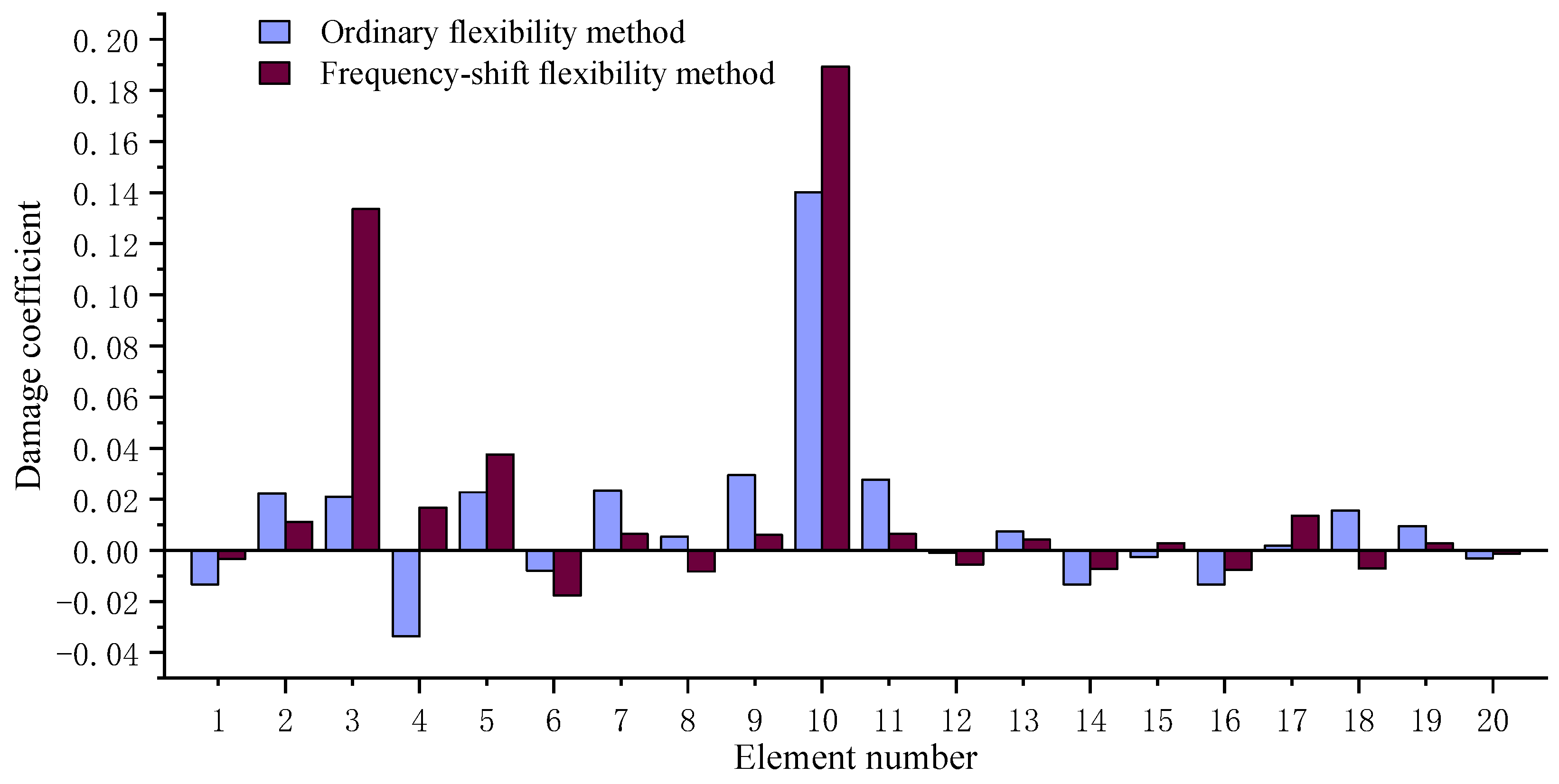
| Damaged Element Number | True Value | Ordinary Flexibility Method | Frequency-Shift Flexibility Method with μ = 0.9λd1 |
|---|---|---|---|
| 3 | 0.1 | 0.021 (79.0%) * | 0.1336 (25.1%) |
| 10 | 0.15 | 0.1402 (6.5%) | 0.1894 (26.3%) |
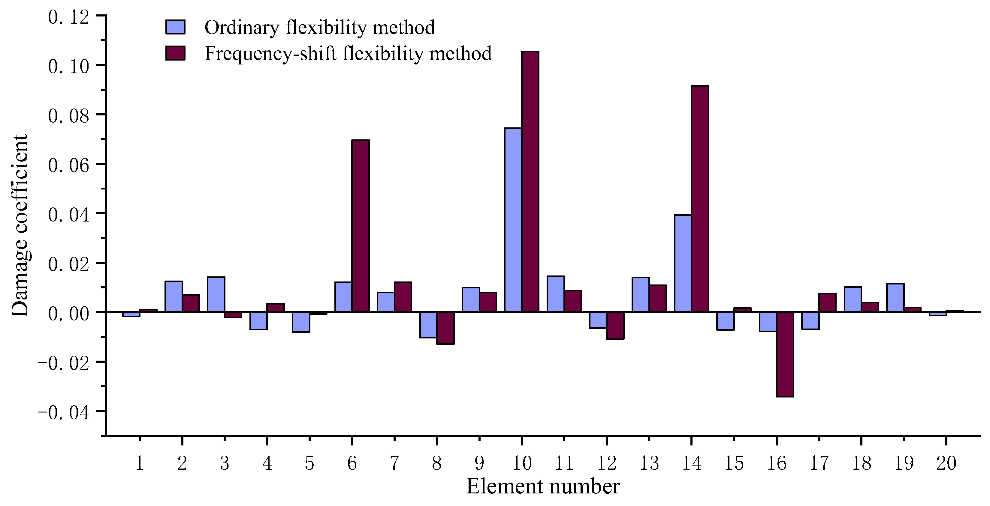
| Damaged Element Number | True Value | Ordinary Flexibility Method | Frequency-Shift Flexibility Method with μ = 0.9λd1 |
|---|---|---|---|
| 6 | 0.1 | 0.0122 (87.8%) * | 0.0696 (30.4%) |
| 10 | 0.1 | 0.0745 (25.5%) | 0.1055 (5.2%) |
| 14 | 0.1 | 0.0393 (60.7%) | 0.0916 (8.4%) |
Disclaimer/Publisher’s Note: The statements, opinions and data contained in all publications are solely those of the individual author(s) and contributor(s) and not of MDPI and/or the editor(s). MDPI and/or the editor(s) disclaim responsibility for any injury to people or property resulting from any ideas, methods, instructions or products referred to in the content. |
© 2023 by the authors. Licensee MDPI, Basel, Switzerland. This article is an open access article distributed under the terms and conditions of the Creative Commons Attribution (CC BY) license (https://creativecommons.org/licenses/by/4.0/).
Share and Cite
Cao, S.; Yang, Q.; Peng, X. Structural Damage Identification Using the First-Order Vibration-Mode-Based Frequency-Shift Flexibility Sensitivity Algorithm. Axioms 2023, 12, 551. https://doi.org/10.3390/axioms12060551
Cao S, Yang Q, Peng X. Structural Damage Identification Using the First-Order Vibration-Mode-Based Frequency-Shift Flexibility Sensitivity Algorithm. Axioms. 2023; 12(6):551. https://doi.org/10.3390/axioms12060551
Chicago/Turabian StyleCao, Shanshan, Qiuwei Yang, and Xi Peng. 2023. "Structural Damage Identification Using the First-Order Vibration-Mode-Based Frequency-Shift Flexibility Sensitivity Algorithm" Axioms 12, no. 6: 551. https://doi.org/10.3390/axioms12060551