Article

Mathematical Description of the Aerodynamic Characteristics of Stationary Flows in a Vertical Conical Diffuser When Air Is Supplied through Various Tube Configurations

Turbines and Engines Department, Ural Federal University named after the first President of Russia B.N. Yeltsin, Str. Mira, 19, 620002 Yekaterinburg, Russia
Axioms 2023, 12(3), 244; https://doi.org/10.3390/axioms12030244
Submission received: 25 January 2023 / Revised: 23 February 2023 / Accepted: 24 February 2023 / Published: 27 February 2023
(This article belongs to the Special Issue Applied Mathematics in Energy and Mechanical Engineering)

Abstract

:
Conical diffusers of various configurations are used in many kinds of technical equipment and manufacturing processes. Therefore, it is a relevant objective to obtain reliable experimental and mathematical data on the aerodynamic characteristics of diffusers. This article presents experimental data on the aerodynamics of stationary flows in a vertical conical diffuser when air is supplied through tubes with various cross sections (circle, square, and triangle). Instantaneous values of air flow velocity are measured with a constant-temperature hot-wire anemometer. Data are obtained on the velocity fields and turbulence intensity along the height and the diameter of the diffuser’s cylindrical part when air is supplied through tubes of various configurations. It is established that air supply through profiled tubes has a significant effect on the shape of the velocity field and turbulence intensity in a vertical conical diffuser. For example, higher values of turbulence intensity are typical of air supplied through profiled tubes (the differences reach 50%). A mathematical formulation (linear and exponential equations) of the change in the average speed and intensity of air flow turbulence along the height of the diffuser’s cylindrical part for various initial conditions and supply tube configurations is presented. The obtained findings will make it possible to refine mathematical models and update algorithms for engineering the design of diffusers for various engineering processes and pieces of technical equipment.

1. Introduction

In almost all branches of technology, equipment is used in which the main engineering process is associated with the movement of either liquid or gas. Examples of such equipment are heat exchangers, gas cleaning units, boilers, chemical equipment, industrial furnaces, various types of dryers, ventilation devices, and nozzle systems. Almost all these devices have a working chamber or supply channels with a conical diffuser [1]. The operation of these devices has shown that their calculated efficiency cannot be always achieved [2]. In many cases, this is due to the uneven supply of the working medium to the equipment’s working area and, therefore, the flow’s physical features in the diffuser and corresponding gas-dynamic losses [3,4]. All this testifies to the importance of studying the aerodynamics of process units with conical diffusers from the point of view of gas-dynamic improvement and finding ways to control flow characteristics. Moreover, it is necessary to obtain reliable experimental data on the features of gas flow dynamics and their mathematical formulation in order to improve engineering methods for calculating conical diffusers and to refine mathematical models [5,6].
Presented below is a brief review of classical (fundamental) research and updated knowledge of aerodynamic characteristics in a conical diffuser.
There are basic studies on the gas dynamics of flows in conical diffusers for various designs and at various initial levels of turbulence intensity. For example, A. Klein conducted experiments and examined experimental data on the influence of inlet conditions on conical diffuser characteristics [7]. In particular, the article describes the effects of blocking the thickness of the inlet boundary layer for various forms of inlet flow, turbulence intensity, and Reynolds numbers. K. Jeyachandran and V. Ganesan studied the effect of various gas-dynamic conditions at the diffuser inlet with physical and mathematical modelling [8]. The paper presents an analysis of data on the velocity profiles, pulse power, shape factor, performance, and efficiency of the studied diffusers. P. A. C. Okwuobi and R. S. Azad experimentally studied the flow structure and turbulence characteristics in a conical diffuser with a fully developed inlet flow [9]. As a result, the basic physical laws were established, and recommendations for the design of conical diffusers were formulated [7,8,9].
There are modern studies of the gas-dynamic characteristics of gas flows in various diffuser configurations aimed at clarifying calculation methods, supplementing the knowledge base about the relevant physical mechanisms, and creating original mathematical models [10,11,12,13]. A. Ferrari proposed analytical dependencies that complement the Fanno models relating to viscous adiabatic flow in a pipe with a constant cross section and an inviscid adiabatic flow in a conical diffuser [10]. These new dependences expand the set of exact solutions of gas dynamics and improve the quality of mathematical models. J. Lee and co-authors investigated the features of turbulence and coherent structures in gas flow through a conical diffuser with various opening angles (2°, 4°, and 8°) based on numerical simulation [11]. The data obtained made it possible to refine the physical features of the gas dynamics of stationary flows in diffusers. X. Wu et al. discovered an internal layer in the gas flow through an asymmetric flat diffuser based on physical and mathematical modelling [12]. Other research will improve the engineering design methods for diffusers. Using numerical simulation, F. J. De Souza and co-authors investigated the gas dynamics of an air flow with various particles in a vertical conical diffuser [13]. It was found that even a small number of particles significantly affects the flow’s shape in a diffuser; the flow can stick to the wall under certain conditions.
There is a large amount of applied research on the use of diffusers in various kinds of technical equipment. For example, diffusers are actively used in the organic Rankine cycle [14,15,16,17,18]. In this cycle, the key device is a turbo expander equipped with an outlet diffuser to increase pressure recovery and improve turbine efficiency. A. Zou et al. optimised the diffuser design for a specific turbine based on numerical simulation [14]. B. Dong et al. evaluated the influence of gas parameters at the diffuser inlet on its gas-dynamic characteristics (in particular, the velocity coefficient) with mathematical modelling [15]. C. S. From et al. studied the influence of flow turbulence intensity at the diffuser inlet on gas dynamics and its influence on the performance of a particular turbine [17]. J. A. Keep and co-authors studied the geometry of a combined (annular–radial) diffuser in relation to the gas-dynamic characteristics of flows and turbine efficiency in the Rankine cycle [18].
Diffuser channels are actively used and studied in many other technical applications. For example, it is relevant to optimise the shape and parameters of flows in a diffuser for a mixing chamber in ejectors [19,20], to fine-tune supersonic diffusers [21], to estimate parameters in diffusers for aircraft gas turbine engines [22], to introduce a diffuser into a reactor for ammonia oxidation [23], and to model and improve the aerodynamics of diffusers in a tubular reactor [24] or an industrial furnace [25].
Thus, the performed review showed that the study of gas-dynamic effects in a conical diffuser is an urgent task at present. This is due to the wide range of applications of diffusers in various technical applications such as: the Rankine cycle, gas and steam turbines, mixing chambers, ammonia oxidation reactors, syngas production plants, industrial furnaces, and others.
Based on an analysis of the data of other authors, the following conclusions can be drawn:
-
Gas-dynamic improvement and the development of ways to control the gas dynamics of flows in a conical diffuser remain urgent tasks for fundamental and applied science;
-
Recent research into the gas-dynamic characteristics of flows in conical diffusers is carried out mainly through numerical simulation;
-
There is a lack of reliable experimental data (and their mathematical description) on the gas-dynamic characteristics of flows in a vertical conical diffuser for mathematical model verification.
Consequently, this research’s key objectives are as follows:
-
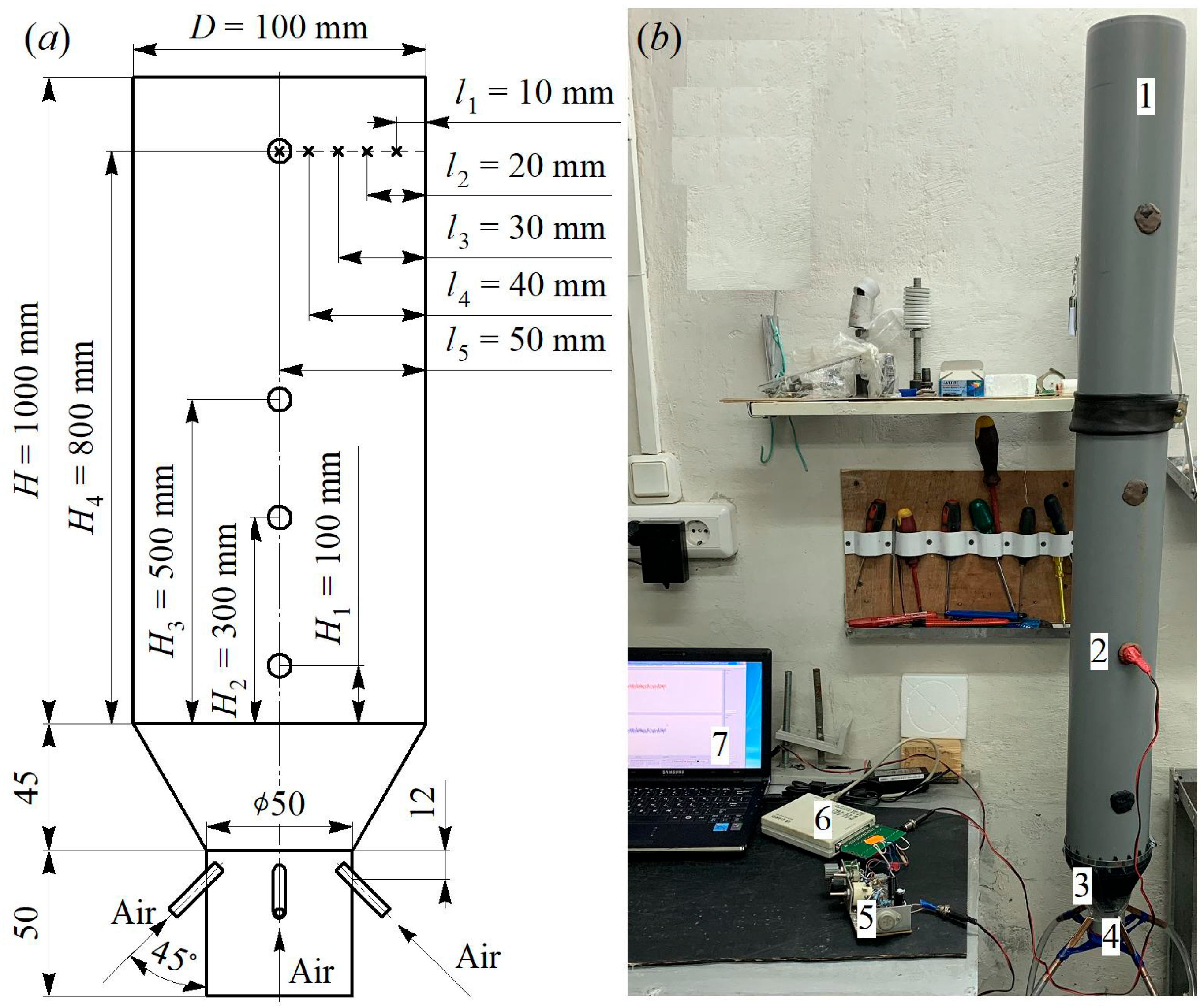
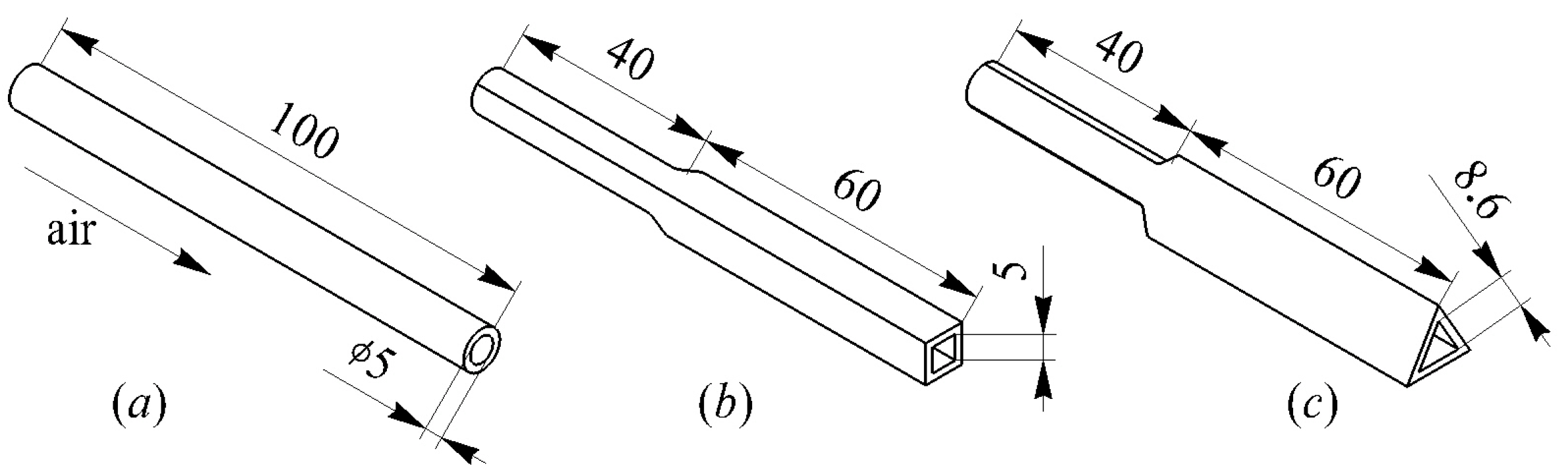
To develop an experimental set-up for studying stationary flows in a vertical conical diffuser when air is supplied through tubes with various cross sections;
-
To choose measuring instruments and research methods taking into account the physical features of the processes under research;
-
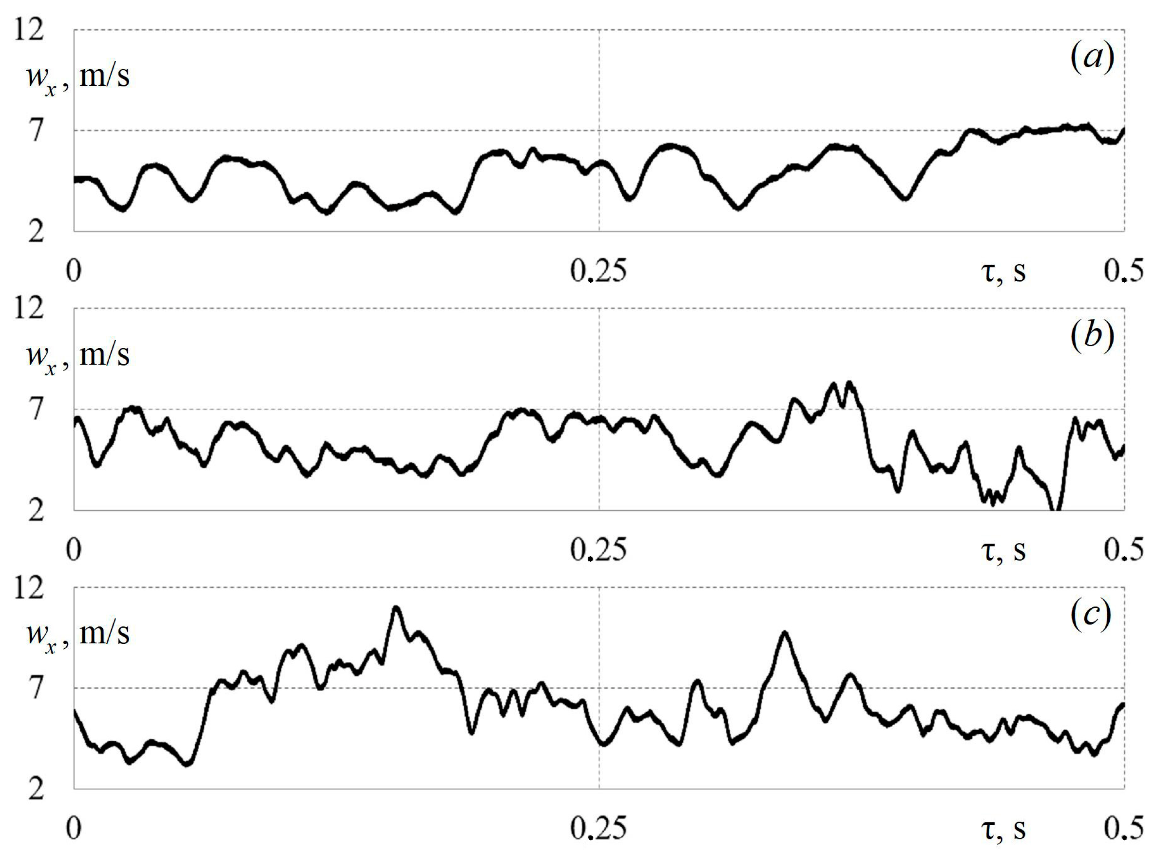
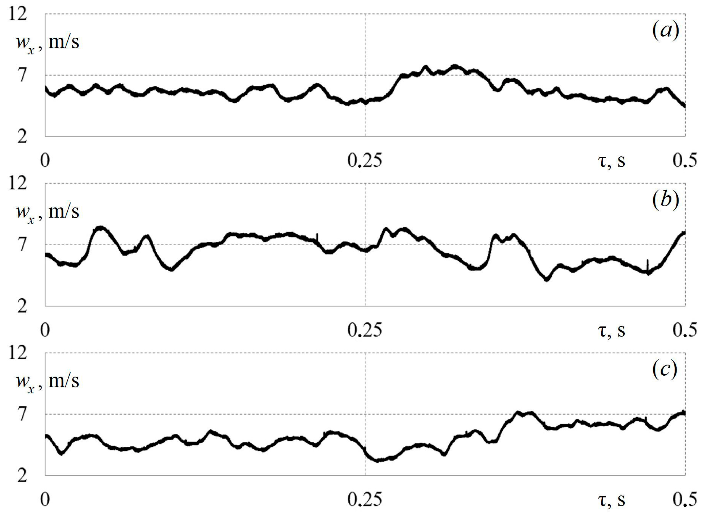
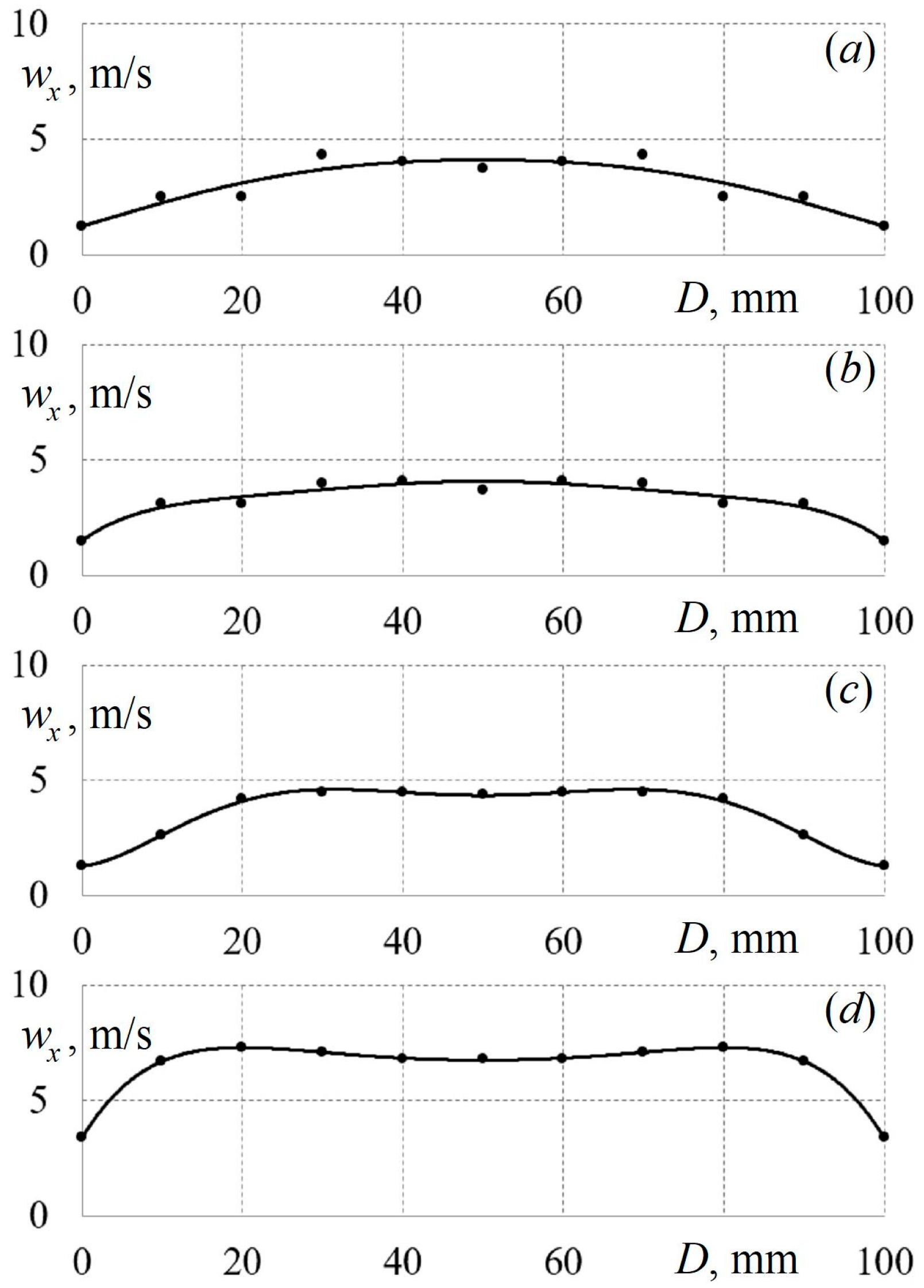
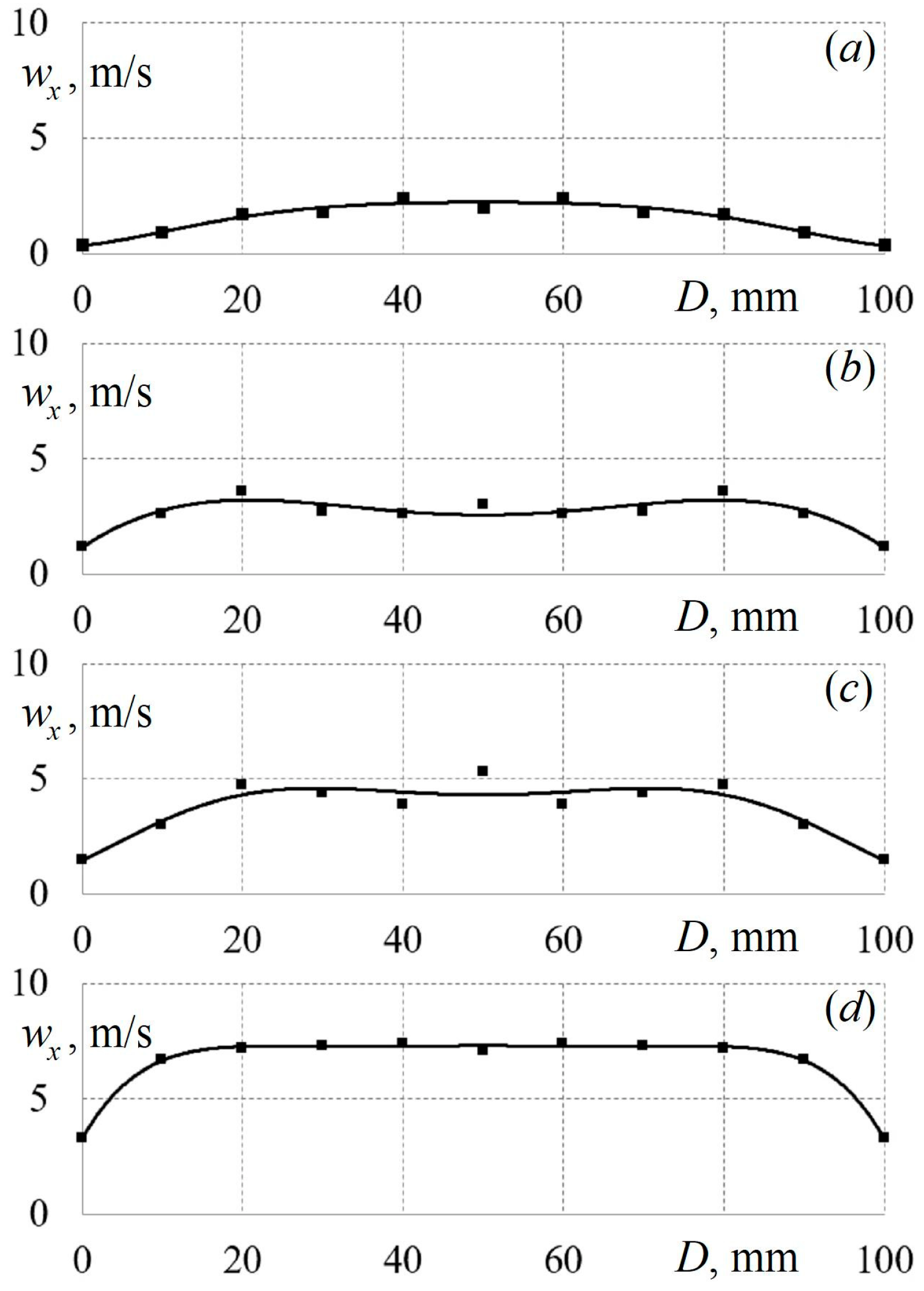
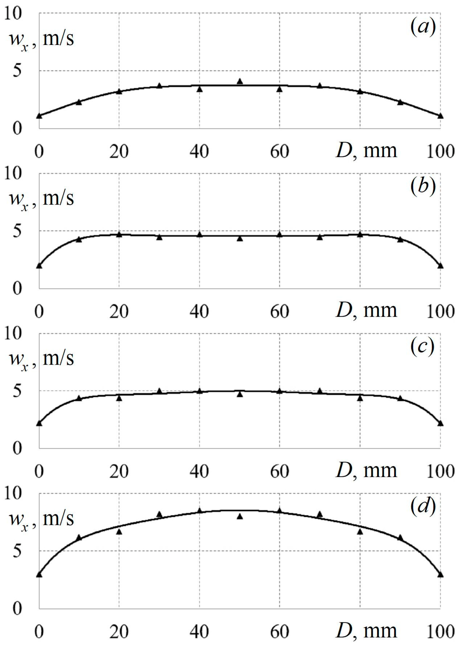
To obtain data on the instantaneous values of the air flow velocity along the height and diameter of the diffuser’s cylindrical part for various initial conditions;
-
To establish the evolution of the velocity fields along the height of the diffuser’s cylindrical part for various configurations of the supply tubes;
-
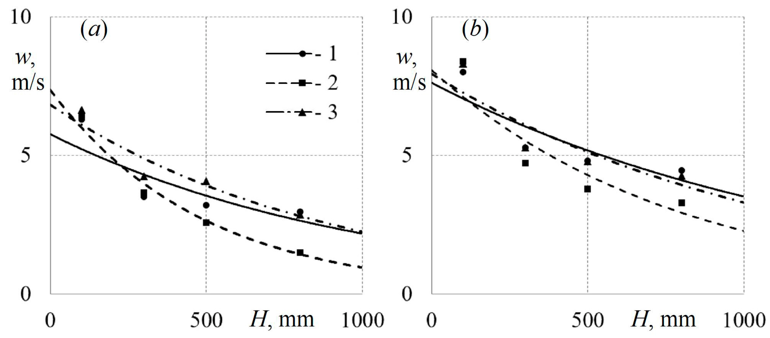
To empirically determine the value of the drop in the average velocity along the height of the diffuser and provide a mathematical description of that process;
-
To establish and mathematically describe the patterns of changes in the intensity of turbulence along the height of the conical diffuser under various initial conditions.

2. Description of the Experimental Measurement Facility

The aerodynamics of stationary flows in a vertical diffuser were studied using a laboratory set-up, the main elements of which are shown in Figure 1.
The main purpose of the installation was to ensure the gas-dynamic characteristics of the air flow remained as similar as possible to real processes in such technical devices. The conical diffuser consisted of three main elements: (1) a base with a diameter of 50 mm, in which four supply tubes were installed at an angle of 45°; (2) a tapered section with a ratio of 1:2 (50 mm by 100 mm); and (3) a cylindrical section with a diameter of 100 mm and a height of 1000 mm. This configuration of the diffuser is used in installations for synthesis gas production. There were four control sections along the height of the diffuser at heights of 100 mm, 300 mm, 500 mm, and 800 mm. In each control section, measurements of the instantaneous values of the air flow velocity along the diameter of the cylindrical part at distances of 10 mm, 20 mm, 30 mm, 40 mm, and 50 mm (in the centre of the diffuser) were made. Measurements of instantaneous velocity values were carried out for 5–10 s for each location of the hot-wire anemometer sensor (primary data). Further processing was carried out in a specialized program (final data).
The working medium in the experiments was air with a temperature of t = 20–22 °C and a barometric pressure of po = 0.1013 mPa. The typical measurement in this work was taken in the control section at a height of 100 mm and the centre of the cylindrical part of the diffuser (at a distance of 50 mm). During the experiments, the average air flow velocity in the typical section varied from 4 m/s to 8 m/s (26,500 < Re < 53,500). Therefore, the flow pattern in this study was developed and turbulent.
The automated measurement system consisted of a hot-wire anemometer with sensors, an analogue-to-digital converter, and a laptop with software. Measurements of the instantaneous values of the air flow velocity wx with a hot-wire anemometer at a constant temperature were made. A nichrome filament with a diameter of 5 μm and a length of 4 mm was used as the sensitive element of the hot-wire anemometer sensor. Five sensors with thread at distances of 10, 20, 30, 40, and 50 mm were made. The data from the hot-wire anemometer (output signal from 0 to 5 V) were received by an analogue-to-digital converter, and then they were transferred to a laptop for processing with custom-made software. The standard relative uncertainty of air flow measurement was 3.6%. The measuring system and the features of its functioning are described in more detail in articles [26,27].
The average flow velocity w at the measuring point was determined as the mathematical expectation of the function wx = f (τ). One of the key aerodynamic characteristics of diffuser flows is the turbulence intensity TI. In this research, TI was calculated as the ratio of the root–mean–square pulsation velocity component to the average velocity of the flow under study [27].
The cross-sectional shape of pipelines has a significant effect on the structure of the flow in them [2,28,29]. Therefore, in this study, air entered the vertical diffuser through supply tubes with various cross-sectional shapes (Figure 2).
The size dimensions of the supply tubes’ cross sections were determined based on the equality of the equivalent hydraulic diameters. Consequently, the round tubes had a diameter of d = 5 mm, the side of the square tubes was also 5 mm, and the side of the tubes with triangular cross sections was 8.6 mm.

3. Results and Analysis of Experimental Findings

Figure 3 shows the primary data as a function wx = f (τ) for the sensor in the first section (H1 = 100 mm) in the centre of the diffuser’s cylindrical part (l5 = 50 mm) when air is supplied through various tube configurations. The data are selected so that the average speed in the first section is approximately the same for all the data presented and is about 4.5 m/s.
Figure 3 shows that the function wx = f (τ) is white noise for all supply tube configurations. At the same time, visual observations show that the use of profiled tubes leads to the creation of small fluctuations in the wx = f (τ) function. This can also be confirmed by the calculated data: TI for round tubes is 0.231 and 0.285 for triangular tubes (almost a 20% difference). This is due to the fact that stable and vortex structures are created in the corners of the profiled tubes, which turbulise the flow in the diffuser. Similar gas-dynamic effects were discovered in [28,29]. It is inappropriate to describe the presented dependencies mathematically, as those data are special cases.
Figure 4 also shows the primary data as the wx = f (τ) function, but for the sensor in the third section (H3 = 300 mm) in the centre of the diffuser’s cylindrical part (l5 = 50 mm) when air is supplied through tube configurations. Based on a comparison of the functions wx = f (τ) in Figure 3 and Figure 4, it is found that there is a significant decrease in small fluctuations in velocity upstream. This indicates a gradual relaxation of the flow along the height of the diffuser’s cylindrical part.
Next, the data in each control section were averaged over the diffuser’s height and diameter. As a result, the velocity fields in the diffuser’s cylindrical part were obtained when air was supplied through tubes with various cross sections (Figure 5, Figure 6 and Figure 7).
Figure 5 shows that there is a decrease in the average flow velocity along the height of the diffuser’s cylindrical part (air supply through round tubes). A change in the velocity field’s shape in the upward flow direction is also observed. Similar results in the case of air supply through profiled tubes were obtained (Figure 6 and Figure 7). There is also a drop in velocity with the diffuser’s height. When air is supplied through triangular tubes, the velocity fields are somewhat different from those in other configurations. This may be due to the influence of the vortex structures that are created at the corners of the triangular tubes.
The detected gas-dynamic effects are preserved for all initial air supply velocities under study and for all configurations of supply tubes. Accordingly, it can be assumed that there is a need for a mathematical formulation of the integral aerodynamic characteristics of flows for the studied configurations of a vertical conical diffuser. These data will make it possible to refine mathematical models and algorithms for the design of diffusers for various pieces of technical equipment.
The velocity fields are a clear illustration of the features of the gas dynamics of flows for different ways of supplying air to the diffuser. The analysis of the velocity field makes it possible to determine the gas-dynamic structure of the flow and draw a conclusion about the behaviour of the working medium in a potential technical device.
Figure 8 shows examples of changes in the turbulence intensity TI along the diameter of the diffuser’s cylindrical part in the first section when air is supplied through tubes of various configurations.
From Figure 8 and the entire array of data obtained, we can draw the following conclusions:
-
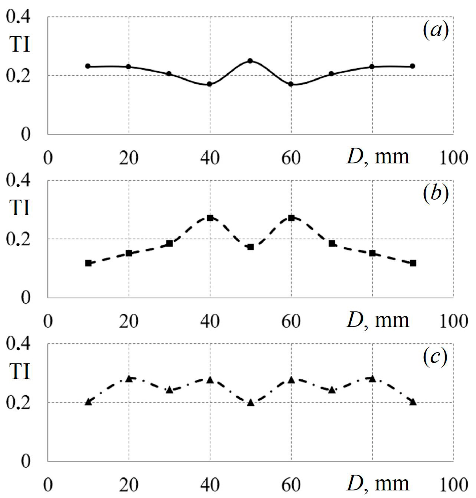
No clear patterns in the change in TI along the diameter of the diffuser’s cylindrical part were found;
-
The influence of the tubes’ cross-sectional shape on the function TI = f (D) has not been established (according to the author, the changes are random);
-
The amplitude of the fluctuations of turbulence intensity values relative to the average value is ±35%;
-
The mathematical formulation of the function TI = f (D) for the cases under study is inappropriate until the physical laws are established.
Data on the turbulence intensity are important for practical applications, as the TI determines the efficiency of mixing of various media, the level of pulsation of the working medium in the flow, the duration of the working medium in the diffuser, and more.
Figure 9 shows the regularities of the drop in the average velocity in the control section along the height of the diffuser’s cylindrical part when air is supplied through tubes with various cross sections for various initial flow rates.
The patterns of speed reduction in the upward flow direction are described with sufficient accuracy by the exponential dependence w = a·eb·H. At the same time, the shape of the tube cross section does not actually affect the intensity of the drop in the air flow velocity along the set-up’s height.
For example, the mathematical description of the change in the average air flow velocity along the height of the diffuser’s cylindrical part, when air is supplied through round tubes with an initial velocity w1 ≈ 6.5 m/s, is described by the following equation (approximation reliability 0.85):
w = 5.7 e 0.0001 H .
Similar relationships for air supply through square and triangular tubes are described by the following equation (w1 ≈ 6.5 m/s, approximation reliability 0.92):
w = 7.1 e 0.00015 H .
The mathematical description of the change in the average air flow rate along the height of the diffuser’s cylindrical part, when air is supplied through round and triangular tubes in the case of an increase in the initial flow rate to w1 ≈ 8.25 m/s, is described by the following equation (approximation reliability 0.83):
w = 7.7 e 0.00085 H .
Similar dependencies for air supply through square tubes are as follows (w1 ≈ 8.25 m/s, approximation reliability 0.86):
w = 8.0 e 0.001 H .
The proposed Equations (1)–(4) for describing the regularities of the average velocity drop in the control section along the height of the diffuser’s cylindrical part when air is supplied through tubes with various configurations are applicable for the indicated velocities and a set-up height of up to 1000 mm.
Figure 10 shows the dependences of the change in the turbulence intensity TI on the value of the average air flow velocity w in the control sections at distances of 100 mm and 800 mm. There is a decrease in TI with an increase in the initial air flow velocity, and this decrease in TI is well described by linear equations. At the same time, the intensity of turbulence has higher values when air is supplied through profiled tubes compared to round tubes. This is also explained by the turbulence of the flow due to the vortex structures typical of profiled channels.
The mathematical description of the function TI = f (w) for the first section (H1 = 100 mm) when air is supplied through round (5), square (6), and triangular (7) tubes has the following form (approximation reliability not less than 0.89):
TI = 0.125 w + 0.286 .
TI = 0.0038 w + 0.21 .
TI = 0.0188 w + 0.369 .
The similar mathematical descriptions of the function TI = f (w) for the fourth section (H4 = 800 mm) when air is supplied through round (8), square (9), and triangular (10) tubes have the forms (approximation reliability not less than 0.92):
TI = 0.0047 w + 0.105 .
TI = 0.0196 w + 0.219 .
TI = 0.017 w + 0.207 .
The proposed equations for describing the patterns of change in the intensity of turbulence from the average air flow velocity along the height of the diffuser’s cylindrical part are applicable for an initial velocity range from 1 to 12 m/s and a set-up height of up to 1000 mm.
The experimental data and proposed description equations can be used to verify mathematical models for modelling aerodynamic processes in a vertical conical diffuser.
Figure 11 shows the experimental dependences of the intensity of turbulence on the height of the diffuser’s cylindrical part for various initial flow velocities when air is supplied through tubes with various cross sections. The distribution of turbulence intensity along the height of the diffuser is important for the design of mixing chambers, industrial furnaces, and synthesis gas plants. Engineers need data on the level of pulsations in the installation to evaluate the efficiency and stability of operation.
Based on the analysis of the TI = f (H) functions, the following conclusions can be drawn:
-
The tubes’ cross-sectional shape has a significant effect on turbulence intensity along the height of the vertical diffuser’s cylindrical part;
-
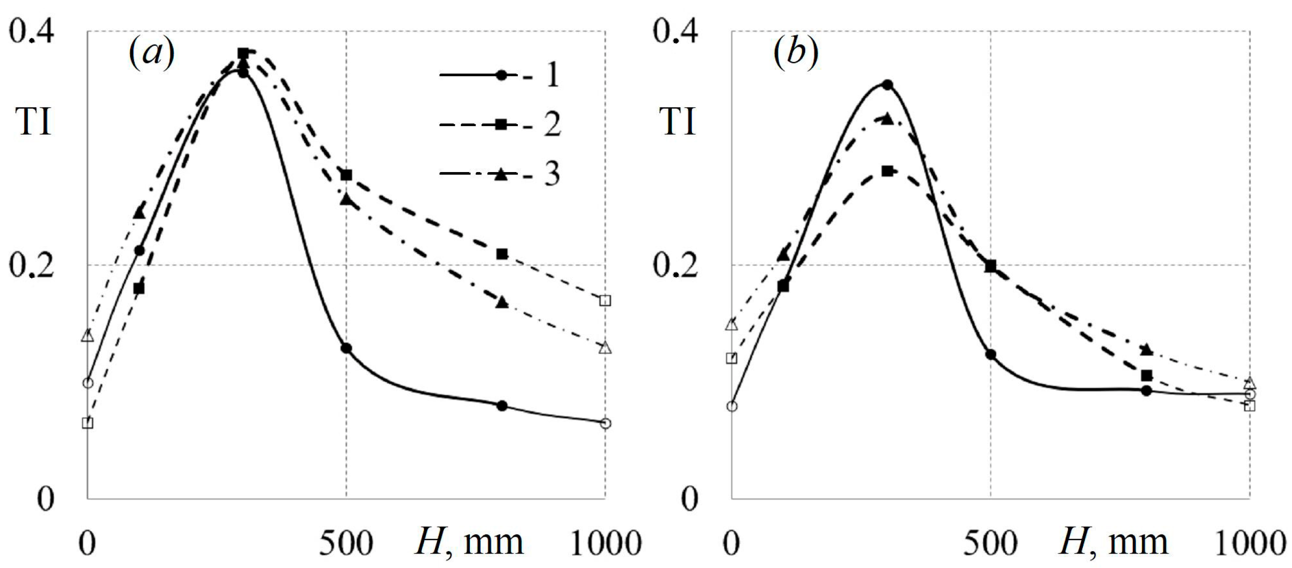
The dependency TI = f (H) has a pronounced maximum in the region of H = 300 mm, which is typical of all initial average flow rates and all configurations of the supply tubes;
-
The turbulence intensity has significantly higher values (up to 50%) when air is supplied through profiled tubes compared to round tubes, which is especially typical of a low initial w.
For the convenience of the mathematical description of the experimental data, it is advisable to divide the TI = f (H) function into two sections: (1) the first section for a height from 0 to 300 mm (section of the growth of turbulence intensity) and (2) the second section for H = 300–1000 mm (TI decline section). For the first section (H = 0–300 mm), the TI = f (H) function for all tube configurations can be described by a linear equation with an approximation confidence of 0.94 (Figure 11a):
TI = 0.00085 H + 0.1 .
Consequently, for the second section (H = 300–1000 mm), the TI = f (H) function can be described by exponential equations for round (12), square (13), and triangular (14) tubes with an approximation confidence of 0.98 (Figure 11a):
TI = 0.254 e 0.001 H .
TI = 0.452 e 0.0003 H .
TI = 0.507 e 0.001 H .
The proposed equations for describing the patterns of changes in the intensity of turbulence along the height of the diffuser’s cylindrical part when air is supplied through tubes with various configurations are applicable for an initial velocity range from 1 to 12 m/s and a set-up height of up to 1000 mm.
It should be noted that all the above formulas are valid only for the studied configuration of the experimental set-up and the initial conditions of air flow. It is necessary to additionally clarify the regularities of changes in the physical characteristics of the flow in the case of a change in geometry or gas-dynamic parameters.
Thus, the aerodynamic characteristics of flows in a vertical conical diffuser can be approximated by relatively simple mathematical expressions that are convenient to use in engineering design.

4. Conclusions

Based on the conducted experimental studies, the following main conclusions can be drawn:
  • Experimental data on the instantaneous values of the stationary flow velocity along the height and diameter of the diffuser’s cylindrical part for various initial conditions and when air is supplied through tubes with different configurations are obtained.
  • The velocity fields along the height of the diffuser’s cylindrical part for various initial conditions when air is supplied through tubes with cross sections in the form of a circle, a square, and a triangle are determined. The evolution of the velocity fields in the upward flow direction is shown.
  • The flow’s turbulence intensity TI along the height and diameter of the diffuser is calculated for various initial conditions and when air is supplied through tubes with various configurations.
  • A mathematical description (exponential equations) of the change in the average flow velocity along the height of the diffuser’s cylindrical part for various initial conditions and configurations of the supply tubes is presented.
  • The regularities of changes in the intensity of turbulence along the height of the diffuser for various initial conditions and tube configurations are established.
  • The obtained data on the aerodynamic characteristics of flows in a conical diffuser can be useful for refining and verifying mathematical models and improving engineering calculations.
  • Further research could be conducted to obtain dimensionless equations for describing the aerodynamic characteristics of flows in vertical diffusers of various designs, as well as to refine mathematical models for modelling aerodynamics.

Funding

The research funding from the Ministry of Science and Higher Education of the Russian Federation (Ural Federal University Program of Development within the Priority-2030 Program) is gratefully acknowledged.

Data Availability Statement

Not applicable.

Conflicts of Interest

The author declares no conflict of interest.

Nomenclature

wxlocal air flow velocity, m/s
waverage flow velocity, m/s
τtime, s
pobarometric pressure, kPa
ttemperature, °C
(d)diameter, mm
llinear dimension, mm
Hheight, mm
ReReynolds number
TIturbulence intensity

References

  1. Japikse, D.; Baines, N.C. Diffuser Design Technology. Concepts ETI: Norwich, UK, 1998; 524p. [Google Scholar]
  2. Idelchik, I.E. Aerohydrodynamics of Technological Apparatuses (Inlet, Outlet and Distribution of the Flow over the Cross Section of the Devices); Mashinostroenie: Moscow, Russia, 1983; 351p. (In Russian) [Google Scholar]
  3. Emmons, H.W. Fundamentals of Gas Dynamics; Princeton University Press: Princeton, NJ, USA, 2015; 783p. [Google Scholar]
  4. Hirsch, C. Numerical Computation of Internal and External Flows: The Fundamentals of Computational Fluid Dynamics; Elesvier: Amsterdam, The Netherlands, 2007; 696p. [Google Scholar]
  5. Yavuz, M.; Sene, N. Approximate solutions of the model describing fluid flow using generalized ρ-laplace transform method and heat balance integral method. Axioms 2020, 9, 123. [Google Scholar] [CrossRef]
  6. Xiao, Y.; Yue, F.; Wang, X.; Zhang, X. Reliability-Based Design Optimization of Structures Considering Uncertainties of Earthquakes Based on Efficient Gaussian Process Regression Metamodeling. Axioms 2022, 11, 81. [Google Scholar] [CrossRef]
  7. Klein, A. Effects of inlet conditions on conical-diffuser performance. J. Fluids Eng. Trans. ASME 1981, 103, 250–257. [Google Scholar] [CrossRef]
  8. Jeyachandran, K.; Ganesan, V. Numerical modelling of turbulent flow through conical diffusers with uniform and wake velocity profiles at the inlet. Math. Comput. Model. 1988, 10, 87–97. [Google Scholar] [CrossRef]
  9. Okwuobi, P.A.C.; Azad, R.S. Turbulence in a conical diffuser with fully developed flow at entry. J. Fluid Mech. 1973, 57, 603–622. [Google Scholar] [CrossRef]
  10. Ferrari, A. Exact solutions for quasi-one-dimensional compressible viscous flows in conical nozzles. J. Fluid Mech. 2021, 915, 915A1-1. [Google Scholar] [CrossRef]
  11. Lee, J.; Jang, S.J.; Sung, H.J. Direct numerical simulations of turbulent flow in a conical diffuser. J. Turbul. 2012, 13, 1–29. [Google Scholar] [CrossRef]
  12. Wu, X.; Schlüter, J.; Moin, P.; Pitsch, H.; Iaccarino, G.; Ham, F. Computational study on the internal layer in a diffuser. J. Fluid Mech. 2006, 550, 391–412. [Google Scholar] [CrossRef]
  13. De Souza, F.J.; Silva, A.L.; Utzig, J. Four-way coupled simulations of the gas-particle flow in a diffuser. Powder Technol. 2014, 253, 496–508. [Google Scholar] [CrossRef]
  14. Zou, A.; Chassaing, J.-C.; Li, W.; Gu, Y.; Sauret, E. Quantified dense gas conical diffuser performance under uncertainties by flow characteristic analysis. Appl. Therm. Eng. 2019, 161, 114158. [Google Scholar] [CrossRef]
  15. Dong, B.; Xu, G.; Li, T.; Quan, Y.; Zhai, L.; Wen, J. Numerical prediction of velocity coefficient for a radial-inflow turbine stator using R123 as working fluid. Appl. Therm. Eng. 2018, 130, 1256–1265. [Google Scholar] [CrossRef]
  16. Kim, D.-Y.; Kim, Y.-T. Preliminary design and performance analysis of a radial inflow turbine for organic Rankine cycles. Appl. Therm. Eng. 2017, 120, 549–559. [Google Scholar] [CrossRef]
  17. From, C.S.; Sauret, E.; Armfield, S.W.; Saha, S.C.; Gu, Y.T. Turbulent dense gas flow characteristics in swirling conical diffuser. Comput. Fluids 2017, 149, 100–118. [Google Scholar] [CrossRef]
  18. Keep, J.A.; Head, A.J.; Jahn, I.H. Design of an efficient space constrained diffuser for supercritical CO2 turbines. J. Phys. Conf. Ser. 2017, 821, 012026. [Google Scholar] [CrossRef]
  19. Wang, W.-B.; Zheng, L.-X.; Lu, W.; Zhang, W.-J.; Xie, C.-X. Study on Structural Design Optimization of Ejector Expansion Chamber. J. Eng. Thermophys. 2021, 42, 309–313. [Google Scholar]
  20. Sierra-Pallares, J.; García del Valle, J.; Paniagua, J.M.; García, J.; Méndez-Bueno, C.; Castro, F. Shape optimization of a long-tapered R134a ejector mixing chamber. Energy 2018, 165, 422–438. [Google Scholar] [CrossRef]
  21. Maicke, B.A.; Bondarev, G. Quasi-one-dimensional modeling of pressure effects in supersonic nozzles. Aerosp. Sci. Technol. 2017, 70, 161–169. [Google Scholar] [CrossRef]
  22. Vinod, L.; Mahendra, M.A.; Mahantayya, K.H. The cfd analysis of subsonic flow around struts of airfoil and cylindrical shape attached to a conical diffuser at exhaust of a gas turbine engine. Int. J. Mech. Prod. Eng. Res. Dev. 2019, 9, 943–954. [Google Scholar]
  23. Moszowski, B.; Wajman, T.; Sobczak, K.; Inger, M.; Wilk, M. The analysis of distribution of the reaction mixture in ammonia oxidation reactor. Pol. J. Chem. Technol. 2019, 21, 9–12. [Google Scholar] [CrossRef]
  24. Huang, Y.; Coggon, M.M.; Zhao, R.; Lignell, H.; Bauer, M.U.; Flagan, R.C.; Seinfeld, J.H. The Caltech Photooxidation Flow Tube reactor: Design, fluid dynamics and characterization. Atmos. Meas. Tech. 2017, 10, 839–867. [Google Scholar] [CrossRef]
  25. Keshavarz, E.; Toghraie, D.; Haratian, M. Modeling industrial scale reaction furnace using computational fluid dynamics: A case study in Ilam gas treating plant. Appl. Therm. Eng. 2017, 123, 277–289. [Google Scholar] [CrossRef]
  26. Plotnikov, L.; Plotnikov, I.; Osipov, L.; Slednev, V.; Shurupov, V. An Indirect Method for Determining the Local Heat Transfer Coefficient of Gas Flows in Pipelines. Sensors 2022, 22, 6395. [Google Scholar] [CrossRef] [PubMed]
  27. Plotnikov, L.V. Thermal-mechanical characteristics of stationary and pulsating gas flows in a gas-dynamic system (in relation to the exhaust system of an engine). Therm. Sci. 2022, 26, 365–376. [Google Scholar] [CrossRef]
  28. Plotnikov, L.V. Unsteady gas dynamics and local heat transfer of pulsating flows in profiled channels mainly to the intake system of a reciprocating engine. Int. J. Heat Mass Transf. 2022, 195, 123144. [Google Scholar] [CrossRef]
  29. Brodov, Y.M.; Zhilkin, B.P.; Plotnikov, L.V. Influence of Intake/exhaust Channel Lateral Profiling on Thermomechanics of Pulsating Flows. Tech. Phys. 2018, 63, 319–324. [Google Scholar] [CrossRef]
Figure 1. Size dimensions (a) and photograph (b) of the experimental set-up for studying the aerodynamic characteristics of flows in a vertical diffuser: 1—cylindrical part of the set-up; 2—hot-wire anemometer sensor; 3—diffuser; 4—base with supply tubes; 5—hot-wire anemometer for measuring instantaneous values of flow velocity; 6—analogue-to-digital converter; 7—laptop for collecting and processing experimental findings; H, H1H4—height of the cylindrical part in the diffuser; l1l4—linear dimension along the diameter of the cylindrical part of the diffuser.
Axioms 12 00244 g001
Figure 2. Plan view and key dimensions of the tubes for supplying air to the vertical diffuser: (a)—circular tube; (b)—tube with square cross section; (c)—tube with triangular cross section.
Axioms 12 00244 g002
Figure 3. Dependences of local values of air flow velocity wx on time τ in the first control section (H1 = 100 mm) for a sensor in the centre of the installation (l5 = 50 mm) for supply tube configurations: (a)—round tube (average parameters in cross section: w1 = 4.2 m/s, TI = 0.231); (b)—square tube (w1 = 4.45 m/s, TI = 0.18); (c)—triangular tube (w1 = 4.48 m/s, TI = 0.285).
Axioms 12 00244 g003
Figure 4. Dependences of local values of air flow velocity wx on time τ in the third control section (H3 = 500 mm) for a sensor in the centre of the set-up (l5 = 50 mm) for various supply tube configurations: (a)—round tube (average parameters in the section: w3 = 4.81 m/s, TI = 0.124); (b)—square tube (w3 = 4.85 m/s, TI = 0.313); (c)—triangular tube (w3 = 4.79 m/s, TI = 0.199).
Axioms 12 00244 g004
Figure 5. Change in local values of the flow velocity wx along the cylinder diameter D when air is supplied to the diffuser through round tubes for the initial average flow velocity in the first section w1 ≈ 6.31 m/s along the set-up height: (a)—H4 = 800 mm; (b)—H3 = 500 mm; (c)—H2 = 300 mm; (d)—H1 = 100 mm.
Axioms 12 00244 g005
Figure 6. Change in local values of the flow velocity wx along the cylinder diameter D when air is supplied to the diffuser through square tubes for the initial average flow velocity in the first section w1 ≈ 6.45 m/s along the set-up height: (a)—H4 = 800 mm; (b)—H3 = 500 mm; (c)—H2 = 300 mm; (d)—H1 = 100 mm.
Axioms 12 00244 g006
Figure 7. Change in local values of the flow velocity wx along the cylinder diameter D when air is supplied to the diffuser through triangular tubes for the initial average flow velocity in the first section w1 ≈ 6.65 m/s along the set-up height: (a)—H4 = 800 mm; (b)—H3 = 500 mm; (c)—H2 = 300 mm; (d)—H1 = 100 mm.
Axioms 12 00244 g007
Figure 8. Change in turbulence intensity TI (in the first section H1 = 100 mm) along the cylinder diameter D when air is supplied to the diffuser through tubes of various configurations: (a)—round tube (w1 ≈ 6.65 m/s, TI1 = 0.213); (b)—square tube (w1 ≈ 6.45 m/s, TI1 = 0.180); (c)—triangular tube (w1 ≈ 6.65 m/s, TI1 = 0.245).
Axioms 12 00244 g008
Figure 9. Dependences of the average air flow rate w along the installation height H when air is supplied through round (1), square (2), and triangular (3) tubes for the initial average flow rate in the first section: (a)—w1 ≈ 6.5 m/s; (b)—w1 ≈ 8.25 m/s.
Axioms 12 00244 g009
Figure 10. Dependences of the turbulence intensity TI on the average air flow velocity w when air is supplied through round (1), square (2), and triangular (3) tubes for various control sections: (a)—control section at the height of H1 = 100 mm; (b)—H4 = 800 mm.
Axioms 12 00244 g010
Figure 11. Dependences of the intensity of turbulence TI on the height of the diffuser H when air is supplied through round (1), square (2), and triangular (3) tubes for the initial average flow velocity in the first section: (a)—w1 ≈ 6.5 m/s; (b)—w1 ≈ 8.25 m/s.
Axioms 12 00244 g011
Disclaimer/Publisher’s Note: The statements, opinions and data contained in all publications are solely those of the individual author(s) and contributor(s) and not of MDPI and/or the editor(s). MDPI and/or the editor(s) disclaim responsibility for any injury to people or property resulting from any ideas, methods, instructions or products referred to in the content.

