1. Introduction
Due to high ground pressure, tectonic movements, and mining induced stress, roadways and their surrounding rock undergo severe deformation and break. As a result, it has become increasingly difficult to maintain roadway stability and sustainable development of many coal mines [
1,
2,
3,
4,
5]. Bolt-grouting support can cement the fragmented rock mass and enhance the integrity and strength of the rock. In this way, the deformation and fragmentation of surrounding rock can be effectively controlled. Therefore, bolt-grouting support is used widely in deep underground roadways [
6,
7,
8]. To explore the influential law of bolting and grouting reinforcement on the mechanical properties of the fractured rock mass, many scholars have conducted numerous experimental studies of grouting reinforcement of broken surrounding rock [
9,
10,
11,
12].
At present, the materials used for grouting reinforcement of broken rock masses are mainly divided into cement-based grouting materials, chemical grouting materials, and organic–inorganic composite grouting materials [
13,
14,
15]. Li et al. [
16] presented the preparation of super early strength grouts. Zhang et al. [
17] developed the self-stress grouting material, which improves the grouting reinforcement effect of fractured rock mass.
In general, for grouting reinforcement problems, many researchers have introduced effective methods and achieved significant effects [
18,
19,
20]. Grassell [
21] used a large model to make a jointed rock mass and then tested the model with mortar anchors to study the strengthening effect of mortar anchors on the model. Salimian et al. [
22] studied the effect of consolidation grouting on the mechanical behavior of fractures based on the characterization of grouting rock fractures. To test the filling process’s effectiveness and the grout’s bonding to the masonry materials, ultrasonic tomography was conducted by Jorne et al. [
23] complemented by mechanical tests. It confirmed the importance of the bond properties of the interfaces (grout–porous medium particles) on the mechanical results.
To further study the reinforcement effect and failure law of the broken rock mass, some scholars have studied the bearing capacity and failure mechanism of broken rock and slurry mixtures. Based on AE monitoring technology and DIC digital image technology, Du et al. [
24] analyzed the damage mechanism and crack development characteristics of coal rock and the filling body during loading. To explore solutions for reinforcement problems of water-rich and broken rock masses in underground engineering, Sha et al. [
25] studied the performance of cement-based grout and its reinforcement effect by designing a new self-developed grouting experimental device. It was pointed out that the rupture interface and tensile fracture of grout were the two main failure modes of reinforcement specimens. Two morphological parameters called “grout vein uniformity” and “block-skeleton conversion ratio” were proposed by Zheng et al. [
26] to quantify the influence of the spatial distribution of the grout vein and rock blocks in a grouted soil rock mixture. Based on the test results of soil–rock mixture, Liu et al. [
27] proposed a theoretical model considering the influence of block ratio, block number, grouting volume and slurry vein distribution.
In summary, the mechanism by which slurry filling can improve the integrity of surrounding rock has been widely recognized. The current research mainly focuses on grouting reinforcement to improve the mechanical strength of the fractured rock mass. There are few studies on the post-peak characteristics of grouting reinforcement stress–strain curves and energy evolution characteristics. However, its post-peak deformation characteristics are of great engineering significance for formulating broken surrounding rock reinforcement schemes and evaluating surrounding rock stability. Therefore, this study selected broken coal with different particle sizes and injected cement-based slurry to make grouting reinforcement to carry out indoor tests. The total stress–strain curve of grouting reinforcement was obtained by a rock rheometer, and the mechanical properties of grouting reinforcement were analyzed. Combined with the AE ringing count, the energy evolution and crack development characteristics during the failure process of grouting-reinforced specimens were studied.
2. Test Preparation
Because of the different crushing degrees of roadway surrounding rock, the support design of bolt-grouting support is particularly prominent. To solve the problem of bolt-grouting support design of surrounding rock with different degrees of fragmentation, this paper conducted indoor experimental research on the grouting reinforcement of broken coal with different particle sizes. Based on the testing, the bearing capacity and secondary damage mechanism of broken surrounding rock after grouting reinforcement were explored.
2.1. Determination of Mechanical Properties of Coal
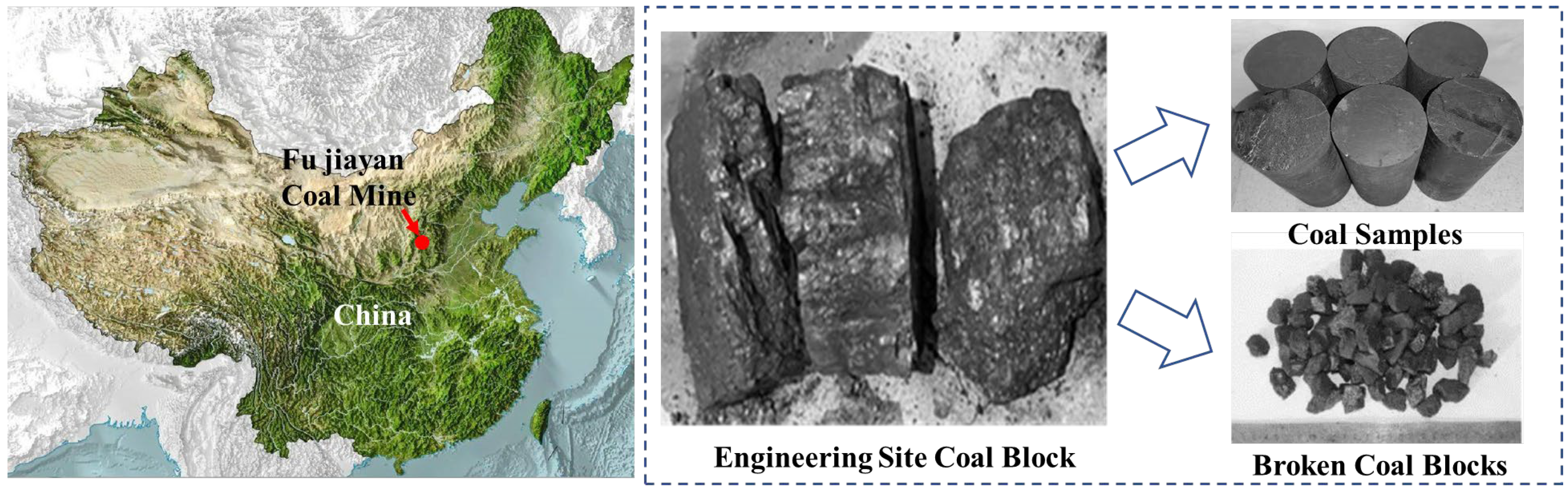
A total of 30 coal specimens were collected from the gas-governance roadway of the Fujiayan coal mine in Shanxi, China. The dimensions of the coal blocks were not less than 25 cm × 25 cm × 25 cm, and coal blocks were made into standard coal specimens and broken coal blocks, as shown in
Figure 1.
- (1)
Broken coal screening
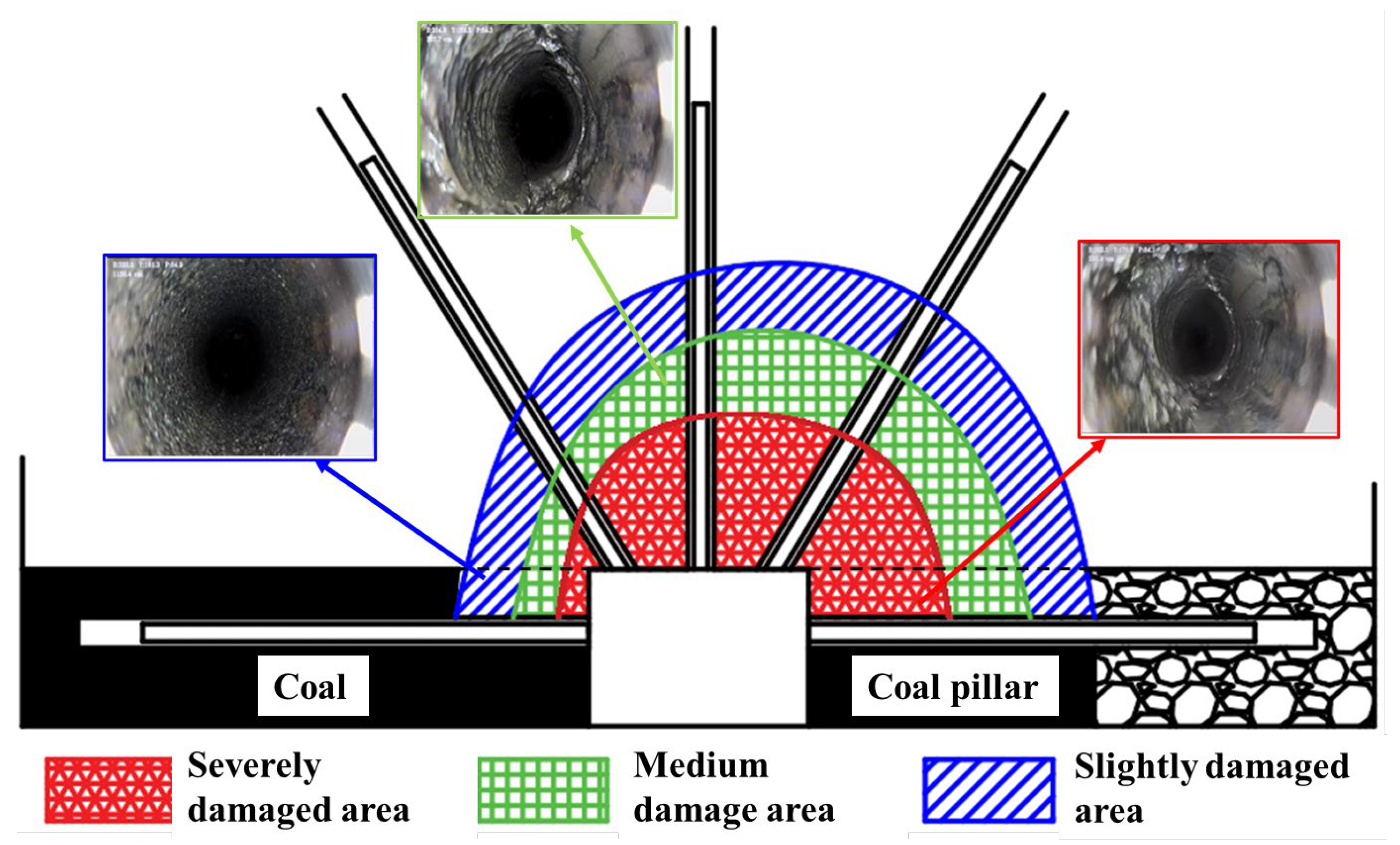
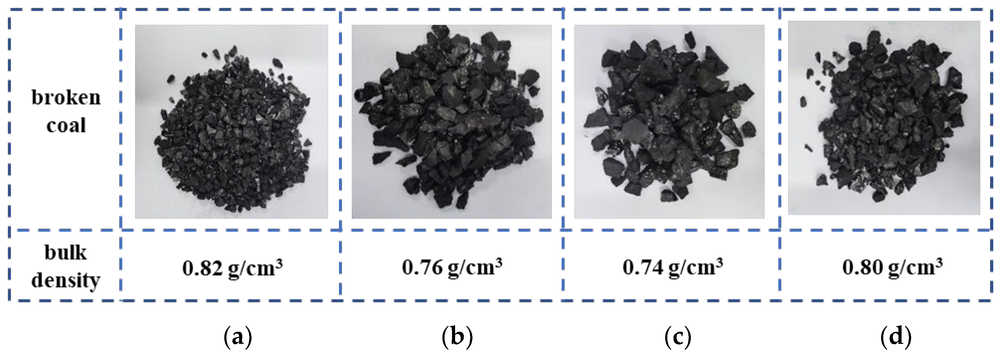
Figure 2 is a schematic diagram of the broken range of surrounding rock obtained from the field survey of the Fujiayan coal mine. The broken range of the surrounding rock is divided into severely damaged, medium-damaged, and slightly damaged areas. In the test, different particle sizes of coal blocks were used to simulate the surrounding rock with different crushing degrees. Therefore, the coal blocks were crushed in the crusher and then screened by different particle sizes of sieves, as shown in
Figure 3.
From
Figure 2, it can be observed that the cracks within the blue box in the slightly damaged zone are small and sparsely distributed, while the cracks within the green box in the moderately damaged zone are beginning to enlarge, with an increasing number. In the severely damaged zone, as indicated by the red box, there are numerous through-cracks and large voids.
- (2)
Production of coal specimens
The on-site coal was processed as follows: The collected coal was processed strictly with the International Society of Rock Mechanics (ISRM) test procedures to prepare a cylindrical specimen with a diameter of about 50 mm and a length of about 100 mm.
- (3)
Strength and deformation failure characteristics of coal specimens
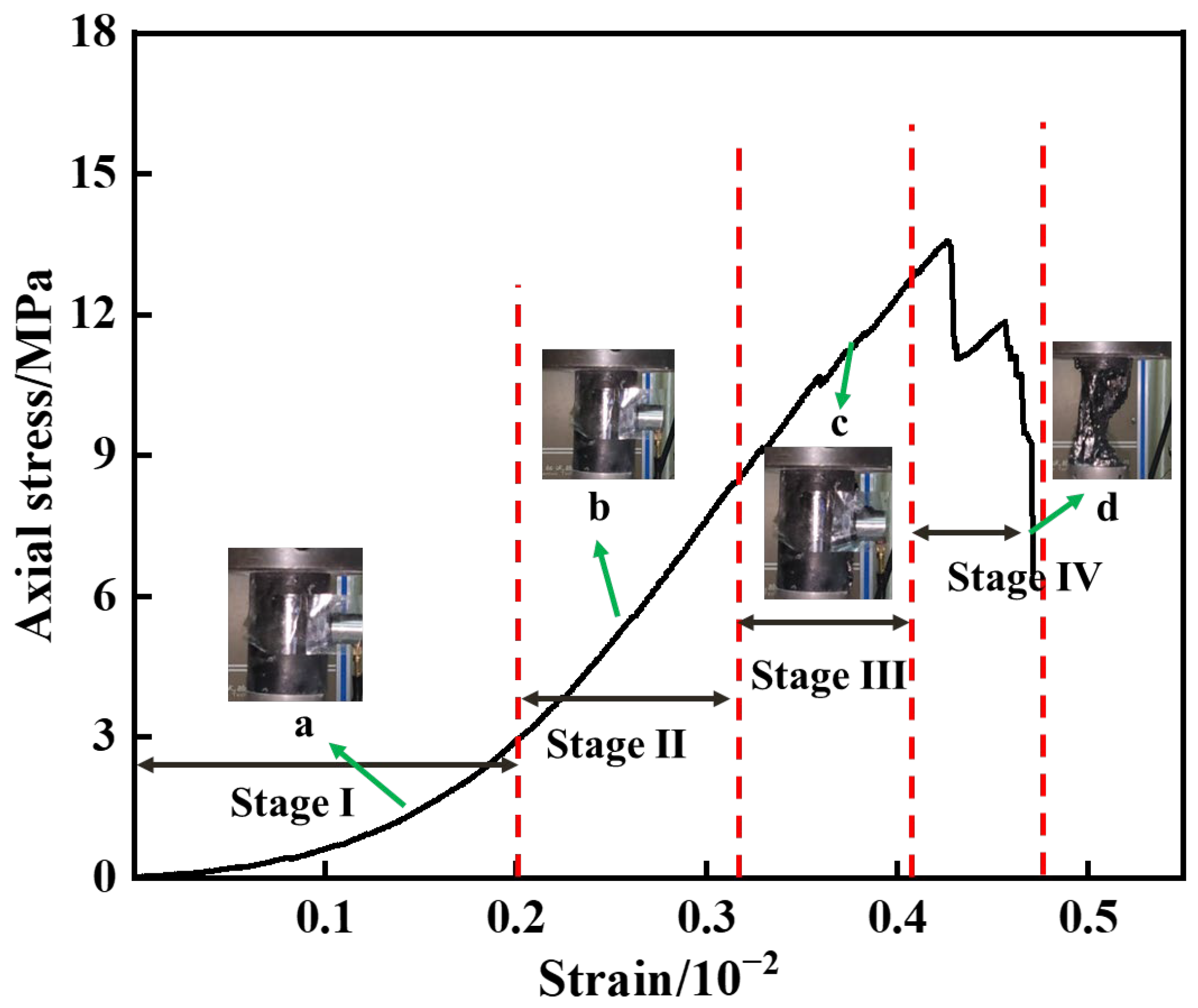
Figure 4 shows that the compressive strength of the coal specimen is 13.25 MPa, and the elastic modulus is 3.4 GPa. The curve after the peak shows the stress decreases sharply, and the coal specimen is rapidly destroyed. The failure stage of the coal specimen has the following characteristics: Stage I (compaction stage) is longer than other stages. This is because there are many voids and cracks inside the coal specimens. Stage IV (micro-crack accelerated expansion stage) is the shortest, indicating that the energy is rapidly released after reaching ultimate strength. The coal specimen fails to form a macroscopic fracture surface.
Figure 5 shows the morphological comparison of coal specimens before and after failure. The failure mode of complete coal specimens is X-type shear failure.
2.2. Performance Test of Grouting Material
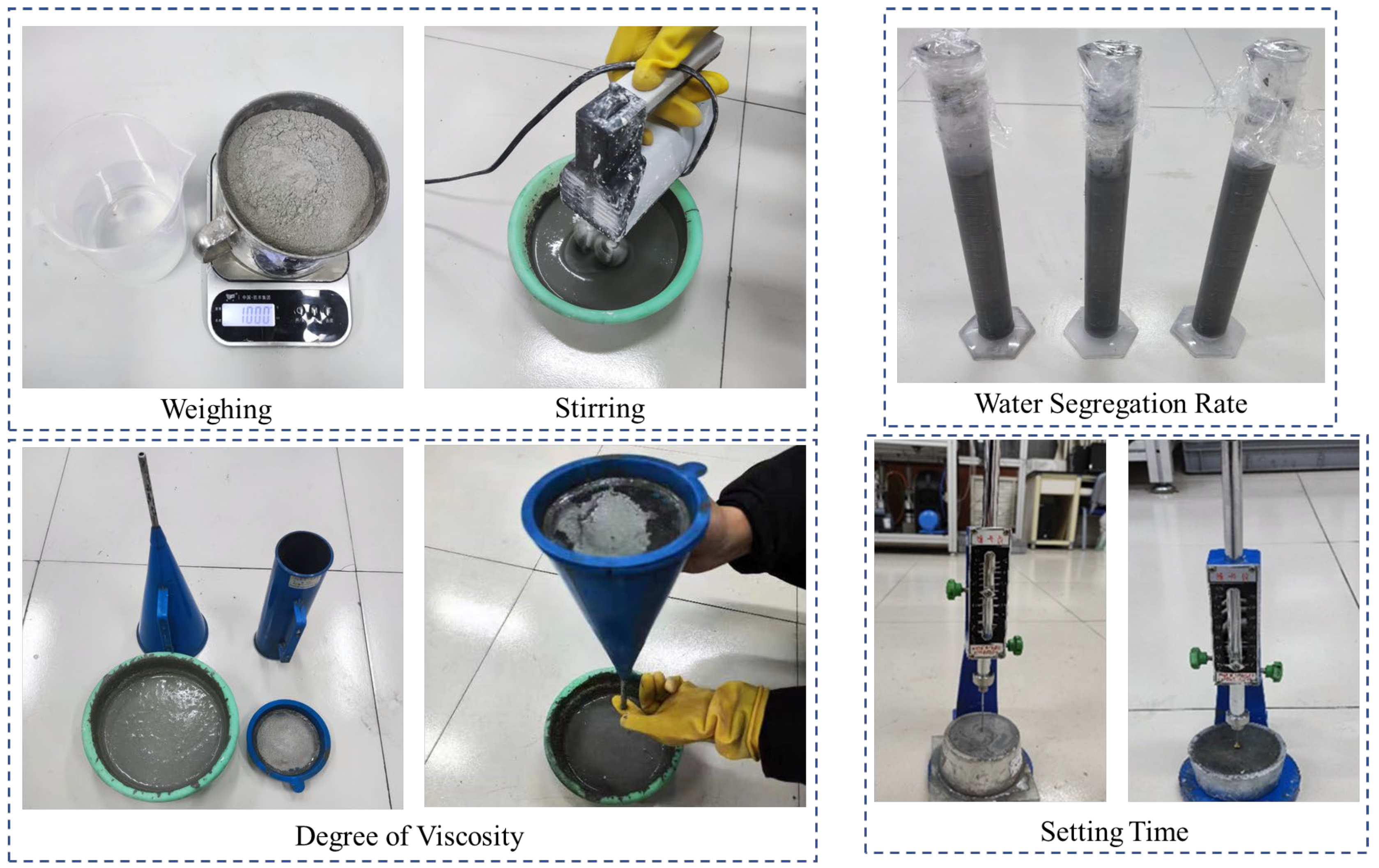
The selected material was cement-based, and had no shrinkage or micro-expansion, and had high fluidity. Firstly, the properties of the slurry were measured. Because the recommended W/C of the material is between 0.3 and 0.5, five kinds of slurry with W/C of 0.3:1, 0.35:1, 0.4:1, 0.45:1, and 0.5:1 were selected to measure the slurry preparation, water segregation rate, determination, viscosity determination, and setting time determination, as shown in
Figure 6.
2.2.1. Determination of Slurry Properties
The specific operation methods were as follows:
Weighed according to different W/C; the mixer was used for rapid stirring for 2 min and low-speed stirring for 1 min. The slurry was stirred well.
- (2)
Determination of water segregation rate
The water separation rate is the percentage of the volume of water separated from the slurry to the volume of the slurry in a certain period. The configured slurry is poured into the measuring cylinder, and the slurry is injected according to the 100 mL scale line. The measuring cylinder of the injected slurry is placed in a flat position, and the upper end is sealed. After standing for 2 h, the data are observed and recorded every 10 min.
- (3)
Determination of Viscosity
The specific determination method is as follows: first, the outlet below the viscometer is sealed by hand, then 600 mL uniform slurry is injected into the funnel, and a measuring cup with a volume of 500 mL is placed underneath. When the lower outlet of the viscometer is released, the timing is started until the lower measuring cup is filled with the slurry, when the timing is stopped. The measured time is the viscosity of the slurry, unit s.
- (4)
Determination Setting time
The determination of condensation time is mainly divided into two parts: initial condensation time and final condensation time. The initial setting time refers to the time required to mix cement-based materials with water until the cement paste begins to lose plasticity. The final setting time refers to the time required to mix cement-based materials with water until the cement paste completely loses its plasticity and begins to have strength.
- (5)
Determination Strength
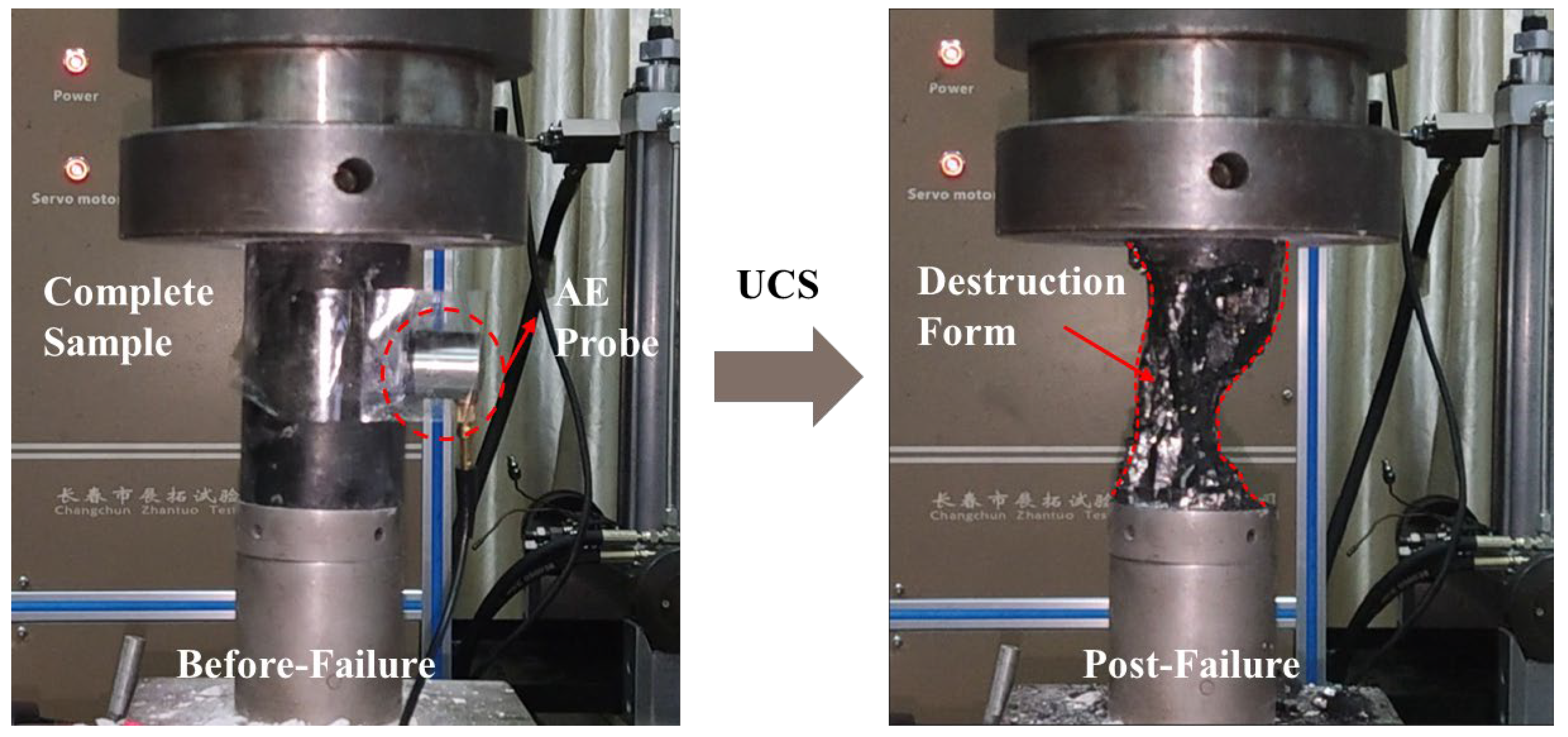
The prepared slurries with different water-to-cement ratios were injected into cylindrical molds with a diameter of Φ50 mm and a height of H100 mm to form slurry specimens. Three pure slurry specimens were prepared for each water-to-cement ratio. The slurry specimens were cured under constant temperature conditions for 28 days, and then the end faces of the specimens were polished. Uniaxial compressive strength tests were conducted using a testing machine, as shown in
Figure 7.
2.2.2. Analysis and Selection of Slurry Parameters
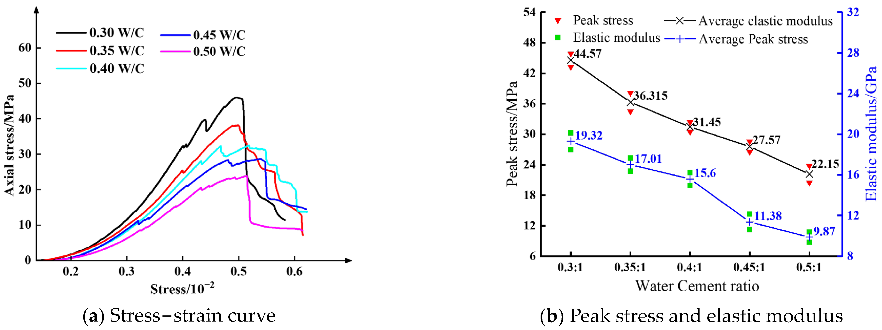
It can be seen from
Table 1 that the water segregation rate of the slurry increases with the increase in the W/C, and the slurry is relatively stable when the W/C is less than 0.45. The viscosity of the slurry is inversely proportional to the W/C. The fluidity of the slurry was found to be better in the range of 0.4–0.45, which is beneficial to the diffusion and injection of the slurry. With the increase in W/C, the setting time of the slurry becomes longer, but in grouting engineering, the setting time of the grouting slurry is at least 2.5 h. The initial setting time of 0.3 and 0.35 of the above W/C is too short, and the setting time of 0.4–0.5 W/C meets the requirements. As shown in
Figure 7b, the strength of a pure slurry specimen decreases with the increase in the W/C, and the elastic modulus becomes smaller and smaller, indicating that the larger the W/C, the stronger the ability to resist elastic deformation. It can be seen from
Figure 7a that with the increase in W/C, the brittle drop after the peak of a pure slurry specimen is increasingly obvious, which is not conducive to the repair of surrounding rock. Considering the above properties of grouting materials, the W/C of 0.45 was selected to simulate the grouting reinforcement test.
2.3. Grouting Solid Test Scheme Design
In grouting engineering, grouting pressure and the particle size of broken coal of the broken rock mass will affect the strength of grouting reinforcement. However, studies have shown that the grouting pressure has a small effect on the mechanical strength of the grouting reinforcement. Therefore, this test did not consider the influence of the grouting process and parameters on grouting reinforcement and only studied the bearing characteristics and damage failure mechanism of the formed slurry–coal mixture.
- (1)
Test scheme
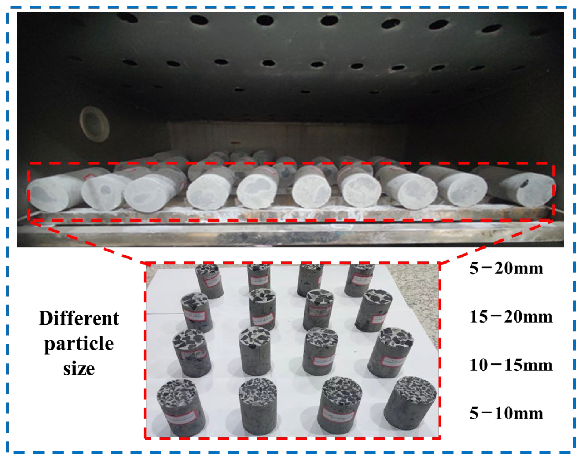
The specimen grouping is shown in
Table 2. Grouting reinforcement was carried out according to the 0.45 W/C measured above, and the compression deformation characteristics of different grouting reinforcement bodies were explored.
- (2)
Setup of test
To make the particle distribution uniform, layered pouring was adopted.
- a.
The grouting material was poured into the mold thickness of about 3–5 mm.
- b.
The broken coal was scattered evenly to cover it with a layer.
- c.
Injection of grouting material was continued to completely cover the coal by 3–5 mm.
- d.
Repeated c, evenly spread the material into the broken coal, and eventually covered the entire mold.
After the grouting of the specimen was completed, the formwork was removed after 48 h of indoor natural maintenance. After 28 days of curing at room temperature, the test was carried out, and the specimens with a large difference in quality were removed to reduce the discreteness. Finally, the conventional uniaxial compression test was carried out, as shown in
Figure 8.
3. Mechanical Properties and Failure Deformation Characteristics after Grouting Modification
Based on the experimental results of complete coal specimens and grouting-reinforced specimens, this chapter presents a comparative analysis in terms of two aspects: failure mode and strength deformation characteristics. The loading rate of the test is 0.06 mm/min.
3.1. Failure Modes
A high-definition digital camera was used to record the failure process during the uniaxial compression process. The failure modes of the grouting-reinforced specimen, the complete coal specimen, and a pure slurry specimen were compared, as shown in
Figure 9.
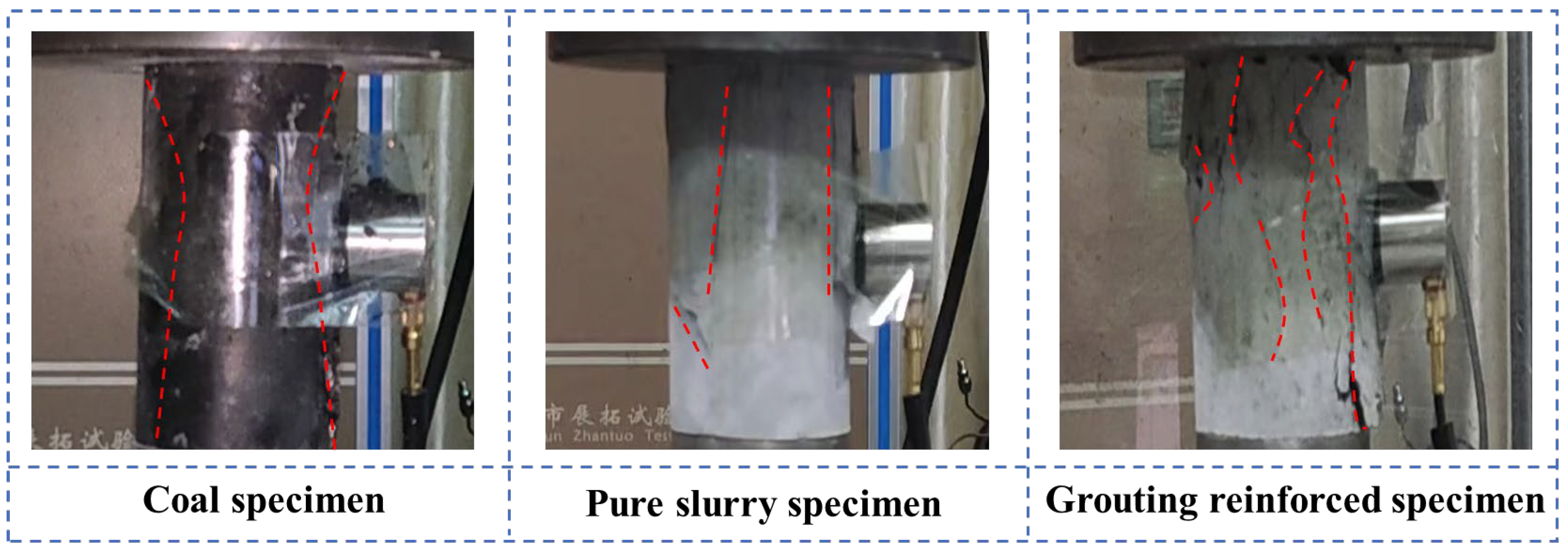
Figure 9 shows that the failure modes of the three specimens are different, mainly as follows:
According to the figures, two vertical cracks appear instantaneously during the compression process of coal specimens. The failure mode of coal specimens is X-type shear failure, and a few macroscopic cracks are seen from crack initiation to complete failure. The pure slurry specimens show typical splitting failure. During the compression process, cracks are generated along the loading direction and run through the entire specimen, and dominate the failure of the specimen.
Compared with homogeneous coal specimens and pure slurry specimens, grouting-reinforced specimens are mainly dominated by tensile failure [
25], showing a progressive failure development law from the surface to the interior, and from local to overall. The macroscopic crack distribution of heterogeneous grouting-reinforced specimens is more complex and diverse. This is because the slurry and coal block are unevenly distributed inside the specimen, and there are many defects, which leads to the transfer of crack initiation to the middle of the specimen. Many irregular cracks dominate the failure of the specimen.
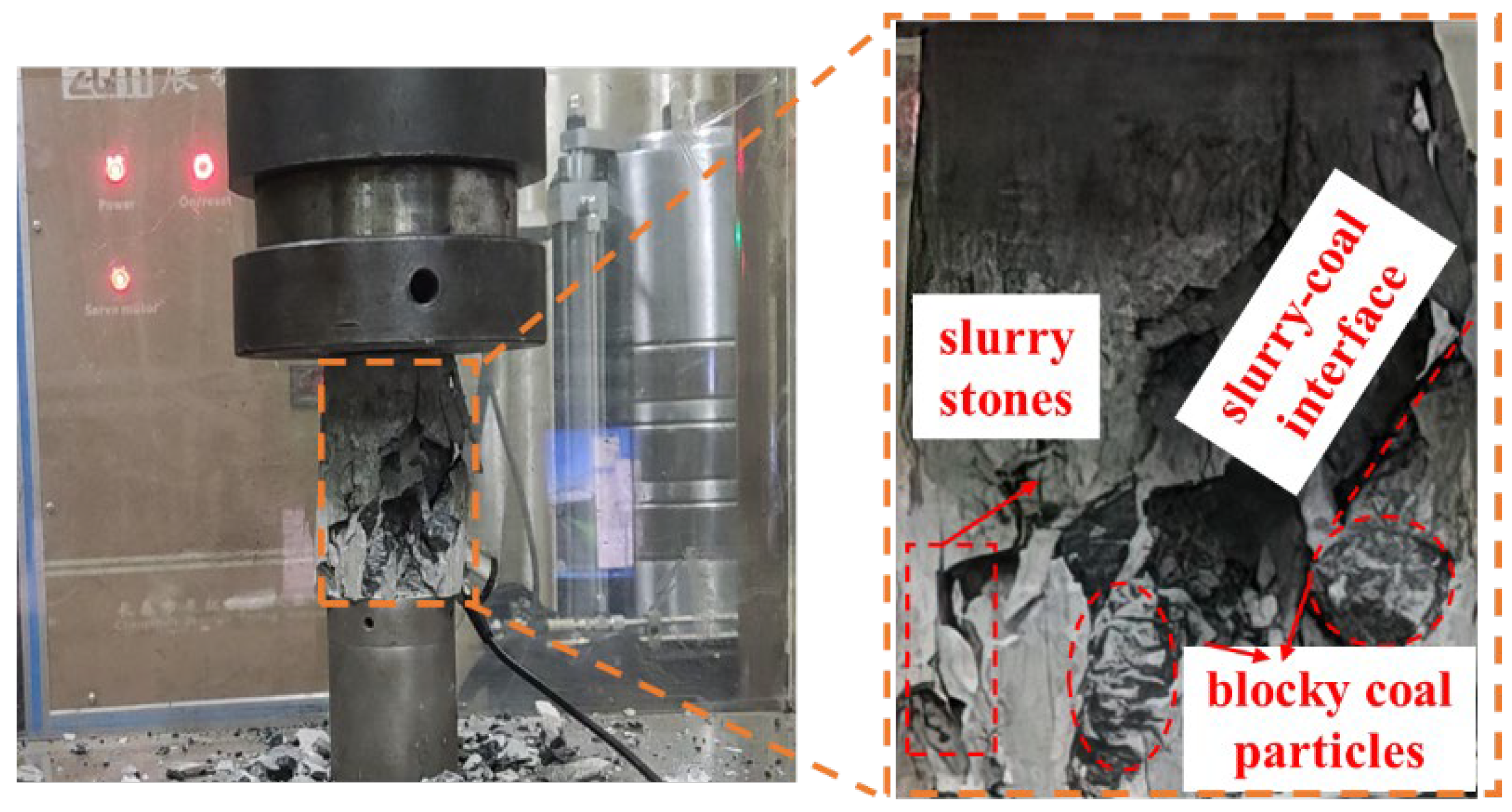
As seen in
Figure 10, there are three kinds of contact in grouting-reinforced specimens: coal–coal, slurry–slurry, and slurry–coal. The weakest contact among these three contacts is the main reason for the failure of grouting-reinforced specimens [
22,
25]. After the compression failure of the specimen, the separation of the slurry–coal contact interface and the presence of massive coal particles and flake slurry stones can be seen. This indicates that the bonding degree of the three kinds of cementation contact in the specimen is different, and the weakest is the bonding between slurry and coal. From the compressive strength of the above pure slurry specimen and the compressive strength of the coal specimen, it can be seen that the contact bonding of slurry–slurry is greater than the contact bonding of coal–coal. Thus, the contact bonding effect from strong to weak is slurry–slurry > coal–coal > slurry–coal.
3.2. Strength Deformation Characteristics
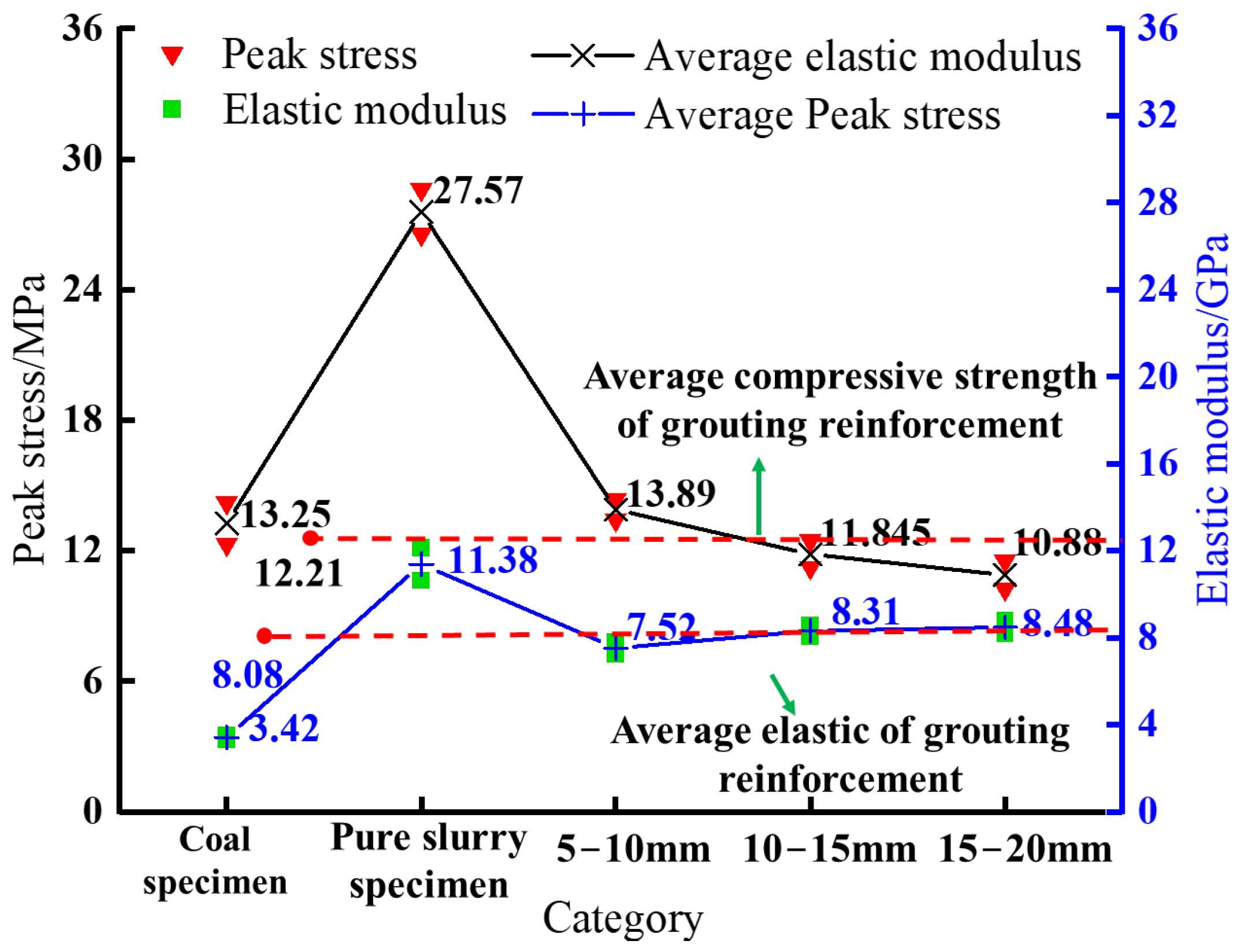
Figure 11 shows that the compressive strength of the pure slurry specimen is 27.57 MPa, and the compressive strength of the complete coal specimen is 13.25 MPa. The average compressive strength of the grouting-reinforced specimens is 13.06 MPa, and the average recovery strength reaches 92.1% of the strength of the complete coal specimen. The main reason for this is that the existence of the slurry increases the strength of the filling between the broken coal blocks and increases the cohesion of the contact surface between the slurry and the coal block. Therefore, the strength of the formed grouting reinforcement is higher, and the strengthening effect of grouting is significant. From the perspective of deformation parameters, the elastic modulus of the complete coal specimen is 3.42 GPa, and the elastic modulus of the pure slurry specimen is 11.38 GPa. The average elastic modulus of the grouting-reinforced specimens is 8.08 GPa. This shows that the average elastic modulus of the reinforced coal block is between the pure slurry specimen and the complete coal specimen, which indicates that the grouting reinforcement not only improves the ability to resist deformation but also does not release a lot of energy in the accumulation of deformation and failure.
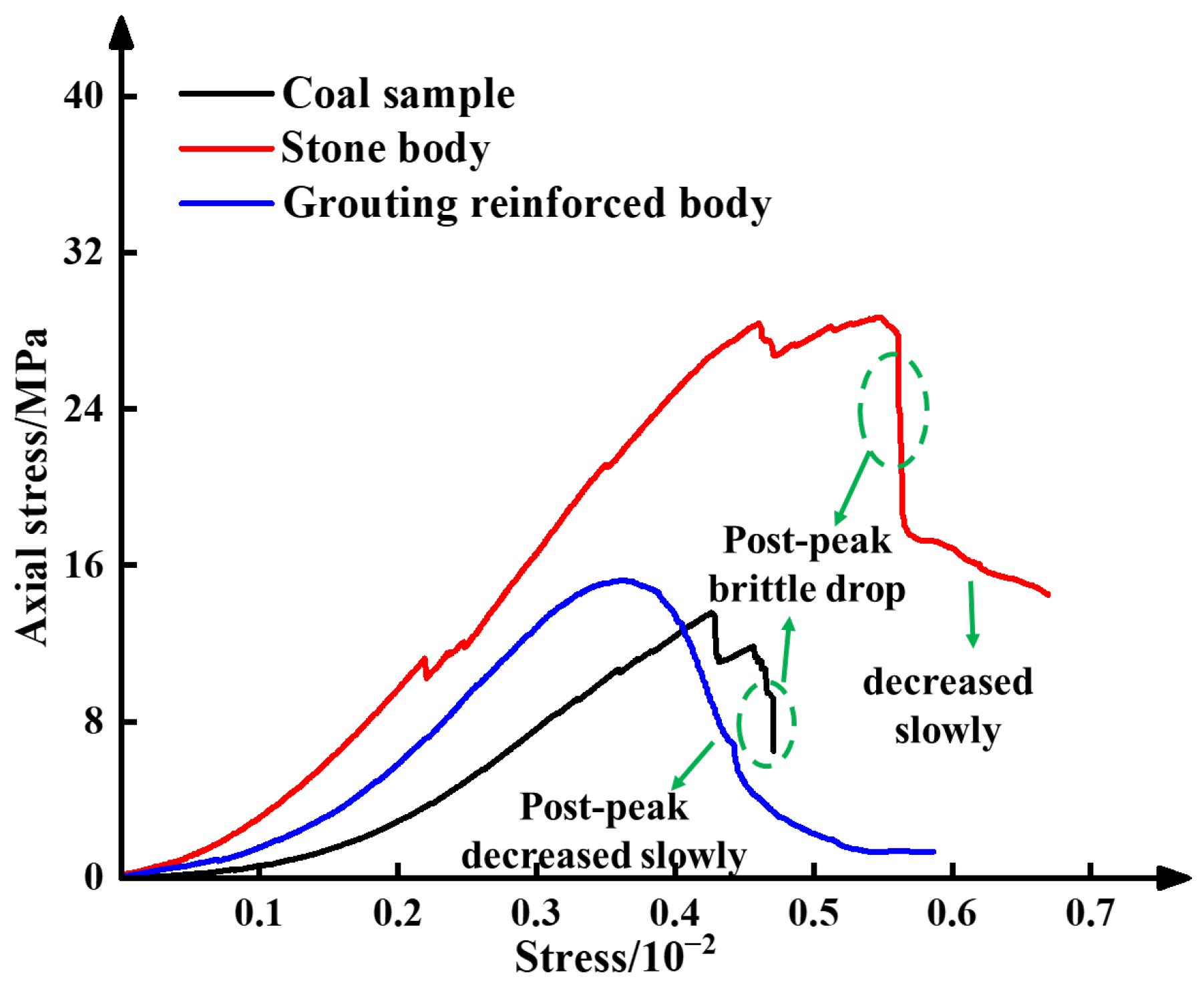
Figure 12 shows the stress–strain curve of the coal specimen, the pure slurry specimen, and the grouting-reinforced specimen. From the perspective of the whole curve shape, in the rising stage, the stress–strain curve characteristics of grouting-reinforced specimens are similar to those of complete coal specimens and pure slurry specimens, and there are fluctuations and nonlinear states. However, in the post-peak stage, the grouting-reinforced specimen shows a completely different curve characteristic from the rock material specimen. Although the loading strength exceeded the peak strength of the grouting-reinforced specimen, it does not immediately lose its bearing capacity. In addition, the internal broken coal body and slurry part still have a certain bearing capacity, and the bearing capacity gradually decreases with the increase in strain, showing an obvious strain-softening phenomenon rather than the typical characteristics of a post–peak steep drop.
4. Failure Law of Grouting Reinforcement with Different Particle Sizes
To solve the problem of surrounding rock reinforcement with different crushing degrees, the strength deformation characteristics and energy evolution characteristics of grouting reinforcement with different broken coal particle sizes were studied to provide a reference for the strength design of grouting reinforcement.
4.1. Characteristics of Voids
The void here refers not to the void inside the specimen but to the filling of slurry in the grouting reinforcement. Studies have shown that the filling distribution of slurry in grouting-reinforced specimens will significantly affect its strength and failure characteristics. Combined with the relevant literature research [
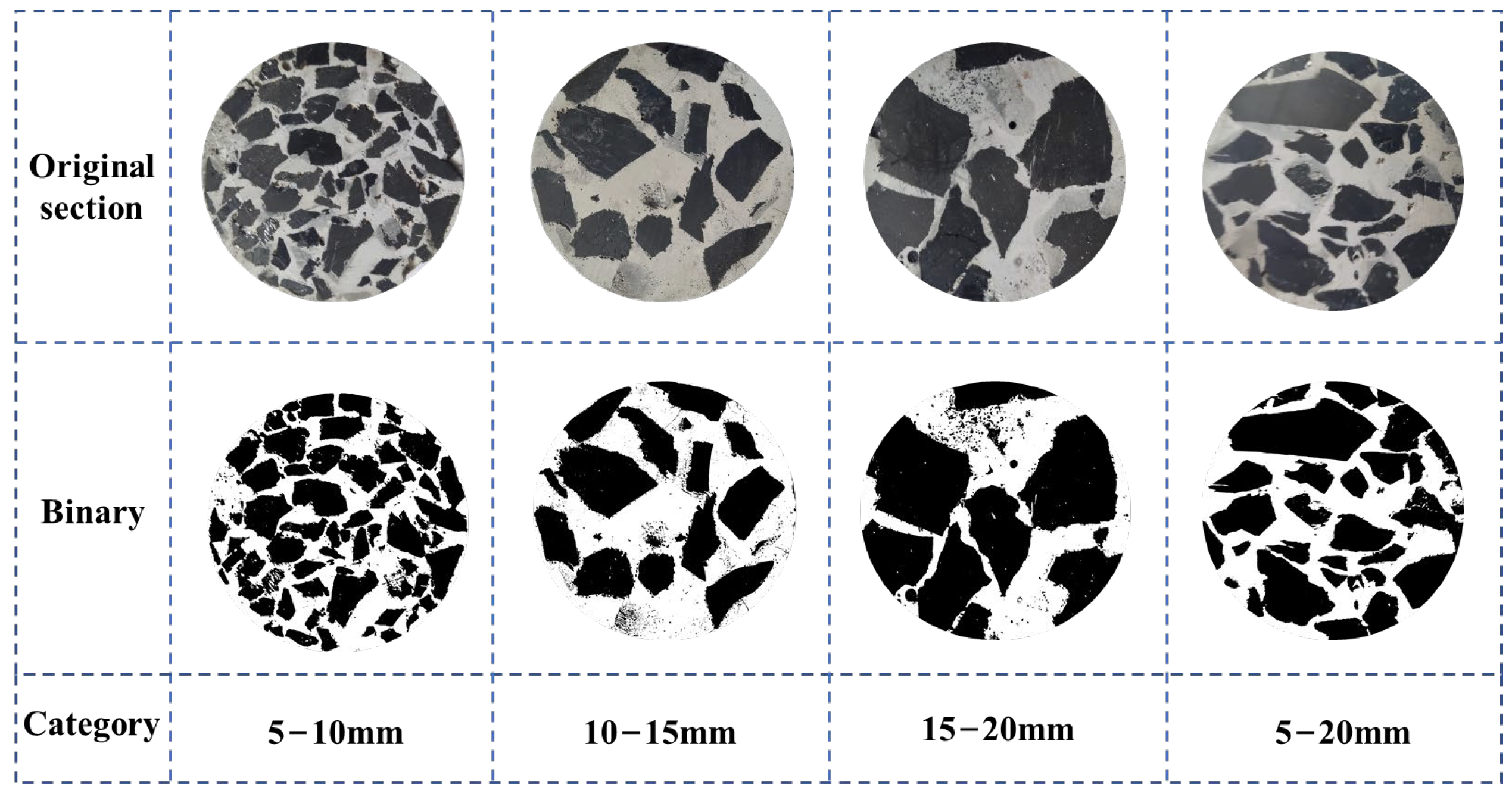
28], this study used the method of cutting sections and used a digital camera to take pictures of the cylindrical end face of the grouting body to obtain the image information of the internal fabric of the grouting-reinforced specimen. The software was used to binarize the image to facilitate the extraction and analysis of the image information and make the gap obvious, as shown in
Figure 13.
Figure 13 shows the size characteristics of the voids in the small-particle-size specimens in the profile; it shows that are many small voids and the distribution characteristics are uniform. There are few voids in the large-particle-size specimens, which are large, and the distribution characteristics are uneven. The contact characteristics between the voids of specimens with different particle sizes and the coal interface are different. The main performance characteristics is that the length of a single coal block–void cementation in the profile is relatively short, which corresponds to the small cementation area of a single coal block and slurry in the specimen. The cementation surface of a single coal block–void of a large-particle-size specimen is relatively long, which corresponds to the large cementation area of a single coal block–slurry in the whole specimen.
4.2. Strength Deformation Characteristics Analysis of Mechanical Properties
The strength deformation characteristics of grouting-reinforced specimens with different particle sizes are shown in
Figure 14. The particle size of the grouting-reinforced specimen is negatively correlated with the compressive strength. When the particle size is 5–10 mm, the compressive strength is the largest, and the compressive strength of the specimen is 13.89 MPa. When the particle size is 15–20 mm, the compressive strength is the smallest, and the compressive strength is 10.88 MPa, which is reduced by 21.6%. The elastic modulus of the grouting-reinforced specimen is positively correlated with particle size. The elastic modulus of 5–10 mm is 7.52 GPa, which is the smallest; for 15–20 mm, the maximum elastic modulus is 8.48 GPa. This shows that although the broken coal body is consolidated into a whole under the action of slurry, the particle size distribution of the coal body inside the specimen and the consolidation effect of the slurry are different, resulting in a large difference in the deformation of the specimen.
The main reason for the change in the strength of different particle sizes is that the specimen has three kinds of bonding contacts: coal–coal, slurry–slurry, and slurry–coal. The first two kinds of contact are relatively stable, and the most easily damaged is slurry–coal contact. The void characteristics characterize the size characteristics of the coal–slurry cementation surface of different particle sizes to a certain extent. This is mainly manifested as void size and void distribution characteristics, which together lead to changes in the strength of different particle-size reinforced bodies. The voids of the specimens with particle sizes of 5–10 mm and 5–20 mm are evenly distributed, the void is small, and the particles are closely bonded. The specimens are denser and can form a stable bearing structure, making the integrity of the specimens stronger. Therefore, the coal and slurry of the small-particle-size specimens will be spread or dispersed during the compression process, which does not easily produce stress concentration, so the specimen cannot be easily damaged. The void between the broken coal blocks with a particle size of 10–15 mm and 15–20 mm is large and the void distribution is uneven. There are many self-consolidation areas inside the grouting reinforcement, and the differentiation area of the coal block is obvious. It is difficult to form a stable bearing structure in the area, so the uniaxial compressive strength of the grouting reinforcement is low.
4.3. Acoustic Emission Characteristics
The distribution characteristics of acoustic emission ringing can reflect the fracture process of grouting-reinforced bodies under static loading [
29,
30], which helps to clarify the damage and failure mechanisms of grouting-reinforced bodies.
The similarities and differences between the two were compared and analyzed to reveal the crack development and energy change of complete coal specimens and grouting-reinforced specimens during loading.
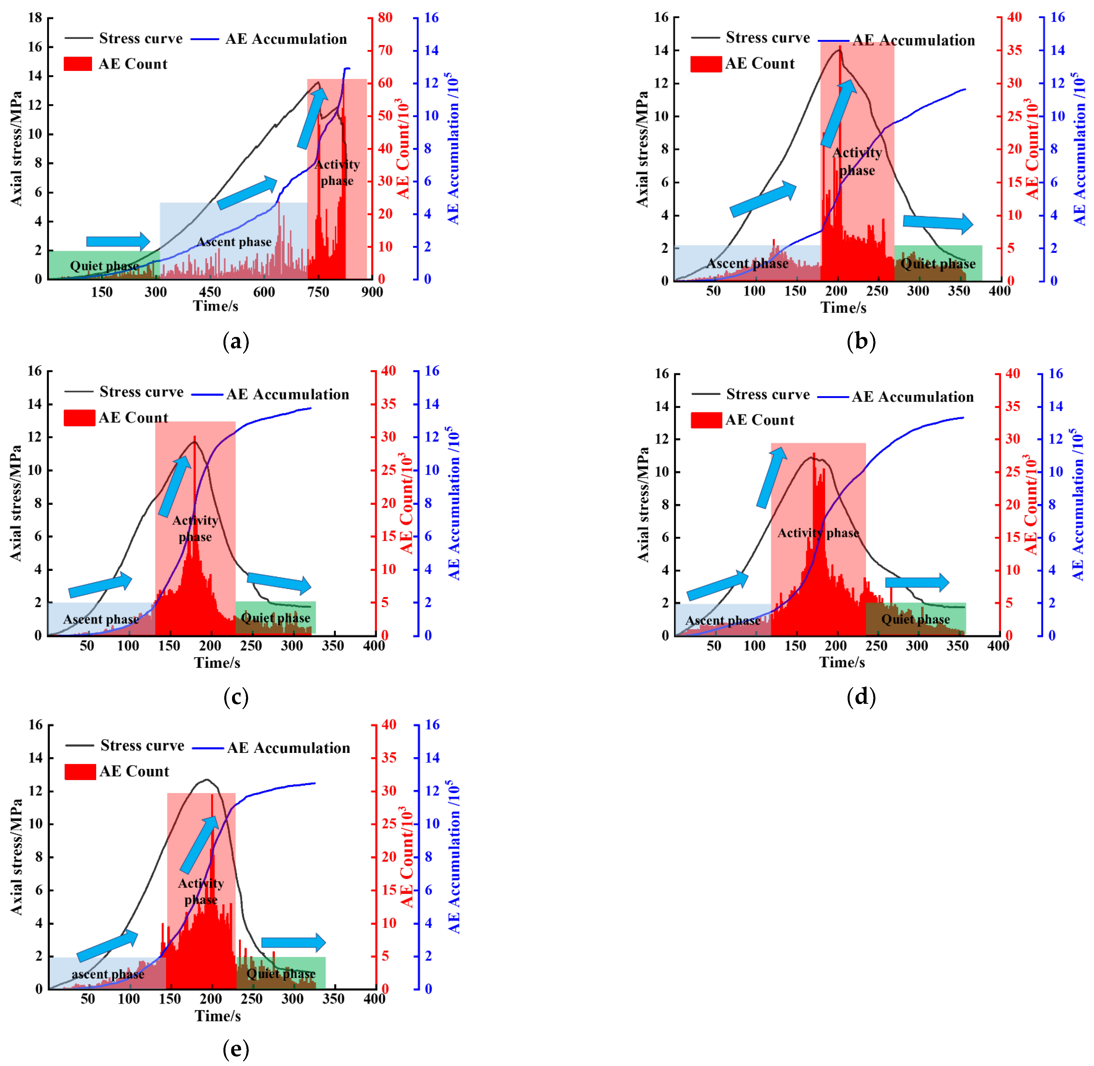
Figure 15 shows coal samples’ acoustic emission signal characteristics and grouting solids with different particle sizes.
As shown in
Figure 15a, the active characteristics of AE ringing of coal specimens first enter the quiet phase, which corresponds to the compaction stage of coal specimens, and there are few AE ringing events. As the loading progresses, the coal specimens enter the elastic and plastic stages successively. The cracks inside the coal specimens begin to penetrate and generate new cracks, and the AE ringing enters the ascent phase. When the loading reaches the peak stress, the coal specimen enters the fracture stage, the macroscopic crack is generated, the specimen is destroyed rapidly, and the AE ringing event enters the active phase. Taking
Figure 15b as an example, the grouting-reinforced specimens first appear in the ascent phase, which is because there are many weak structural planes in the specimen (coal–slurry cementation). The existence of this structural plane leads to a slow and steady increase in the number of AE ringing events in the early stage of compression.
It can be seen from
Figure 15b–e that the AE stage characteristics of grouting-reinforced specimens with different particle sizes are different. With the increase in coal particle size, the span of the AE ascent phase gradually becomes shorter, while the AE active phase increases. Among these, the AE ascent phase of the 5–10 mm particle size event is the longest, including the compaction stage, the elastic stage, and the partial plastic stage; the 10–15 mm and 15–20 mm particle size specimens mainly correspond to the compaction stage and elastic stage of the stress curve. The ascent phase span of the 5–20 mm particle size event is second only to that of the 5–10 mm event. For small-particle-size specimens, the filling slurry between broken coal blocks is small and the cementation is stable. Therefore, the integrity of the formed grouting-reinforced specimen is better. Before reaching the peak strength, there are fewer internal rupture events of the sample, and the number of acoustic emission ringing events is relatively lower, so the rising section is longer.
The main characteristics of the AE active phase are: AE ringing events surge and the AE cumulative number curve increases sharply. The 15–20 mm particle size specimen has the longest AE active phase and the slowest stress drop after the peak of the specimen curve. The length of the AE active phase is closely related to the post-peak strain softening of the grouting reinforcement. The longer the AE active phase, the longer the strain-softening stage of the corresponding curve. It shows that the post-peak ductility of 15–20 mm specimens is better. The AE active phase length of the 5–20 mm particle size specimen is similar to that of the 5–10 mm particle size specimen.
The AE quiet phase mainly corresponds to the stable friction stage after the peak. The grouting reinforcement forms a macroscopic fracture surface, and the specimen is further deformed and destroyed. The friction between the slurry stone body and the coal block generates the AE ringing signal. The AE ringing activity of the grouting-reinforced specimen is relatively frequent in the friction stage.
4.4. Grouting-Reinforced Specimen Crushing Mechanism
The above-mentioned void reaction to the microstructure indicates the cementation of the slurry [
26], and the failure of the cementation is the main reason for the failure of the grouting reinforcement. Therefore, combined with the strength deformation characteristics and the failure law of the grouting reinforcement, a conceptual model was established to analyze the cementation-bearing structure and its causes of failure.
Figure 16 shows the cementation contact of the grouting-reinforced specimen. The gray block represents the coal block, and the red line represents the cementation of the slurry. The main principle of strength recovery of grouting reinforcement is that the slurry bonds the broken coal blocks together to form a stable bearing structure. It can be seen from the figure that the cementation of slurry in grouting reinforcement is structural, which is called a skeleton-bearing structure [
27]. The skeleton-bearing structure formed by the cementation of small-particle-size specimens is dense and stable. The skeleton of a large-particle-size block has a large bearing structure, loose distribution, and uneven distribution.
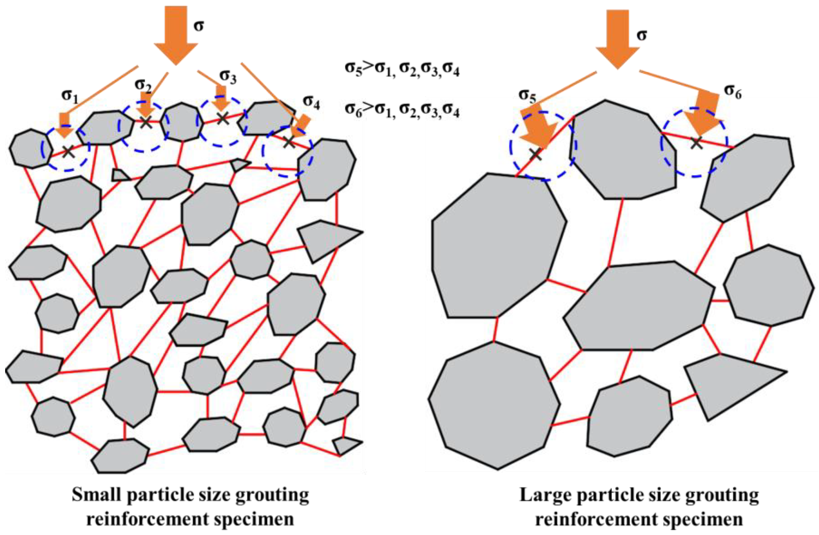
The bearing structure of the cemented skeleton of the specimens with different particle sizes leads to different stress states of the coal–slurry cementation surface during the loading process [
31].
Figure 17 shows the stress state of the coal–slurry cementation surface when the grouting reinforcement specimen is loading. Due to the small size and uniform distribution of coal blocks, the cementation surface of coal slime in the skeleton-bearing structure is relatively dense. The coal and the slurry consolidation body can work together, and the stress at the coal–slurry cementation surface is not easily concentrated. The coal blocks of large-particle-size samples are dispersed, and the coal–slurry cementation surface in the skeleton-bearing structure is loose and the cementation surface area is large. The stress of the coal and slurry consolidation body is not uniform, and stress concentration can easily occur at the coal–slurry cementation surface. Therefore, the large-particle-size samples are more prone to damage and have lower strength.
5. Conclusions
This study mainly examined the change in the bearing capacity of grouting reinforcement after grouting modification and the damage law of grouting reinforcement with different particle sizes. The bearing capacity test of the grouting reinforcement specimen was carried out, and the bearing capacity and post-peak strain-softening characteristics of broken coal after grouting reinforcement were explored. The main conclusions are as follows:
After grouting reinforcement, the recovery strength of the specimen reaches 92.1% compared to the complete coal specimen. Moreover, brittle failure, which is common in typical rock materials, did not occur after the grouting reinforcement peak. Instead, the failure mode was mainly tensile failure. The stress–strain post-peak curve exhibited good ductility and ductile deformation characteristics. Additionally, the AE (acoustic emission) ringing signal stage of the grouting reinforcement differed from that of the complete coal specimen, with the AE active phase appearing in the middle of the compression process. These findings indicate that the post-peak deformation and failure of grouting-reinforced specimens are progressive, with energy release also occurring progressively.
Slurry–coal contact is most easily damaged when using grouting reinforcement. The voids of the small-particle-size specimens are evenly distributed and there are many small voids. In this way, the specimens’ particles are closely bonded and can form a stable bearing structure, which strengthens the specimens’ integrity. Therefore, in the compression process of small-particle-size specimens, the coal block and slurry are easily spread or dispersed under the force. Stress concentration is not easily produced, so the specimen is not easy to destroy.
The elastic modulus and peak strength of grouting reinforcement are negatively correlated with particle size. The AE signal characteristics of different particle sizes of grouting reinforcement were revealed: the smaller the particle size of broken coal in grouting reinforcement, the larger the ascent phase span, the shorter the active phase, the more concentrated the AE ringing, and the worse the ductility after the peak.
Based on the strength and deformation characteristics of the grouting-reinforced materials with different particle sizes, it was found that the optimal timing for grouting is not when the coal particles are larger in size, but rather when a certain degree of fragmentation is achieved (i.e., when the size distribution of the fragmented coal particles is relatively uniform). Grouting at this stage can yield better results, as it can be carried out during periods of intense disturbance and significant fragmentation in the working face when cracks are more prominent and coal fragmentation is more extensive.
Author Contributions
Investigation, L.Y. and Y.C.; writing—original draft preparation L.Y.; writing—review and editing, C.Z. and M.C.; conceptualization M.C.; funding acquisition, M.C.; data curation, C.Z. All authors have read and agreed to the published version of the manuscript.
Funding
This research was funded by the National Natural Science Foundation of China (52004145) and the Natural Science Foundation of Shandong Province (ZR2020QE119).
Data Availability Statement
All data supporting the findings in this study are available from the corresponding author on reasonable request.
Acknowledgments
The authors would like to express their sincere gratitude to the editor and three anonymous reviewers for their valuable comments, which have greatly improved this paper.
Conflicts of Interest
The authors declare that they have no known competing financial interests or personal relationships that could have appeared to influence the work reported in this paper.
References
- Pardoen, B.; Talandier, J.; Collin, F. Permeability evolution and water transfer in the excavation damaged zone of a ventilated gallery. Int. J. Rock Mech. Min. Sci. 2016, 85, 192–208. [Google Scholar] [CrossRef]
- Mandal, P.; Das, A.; Kumar, N.; Bhattacharjee, R.; Tewari, S.; Kushwaha, A. Assessment of roof convergence during driving roadways in underground coal mines by a continuous miner. Int. J. Rock Mech. Min. Sci. 2018, 108, 169–178. [Google Scholar] [CrossRef]
- Wang, F.; Zhang, C.; Wei, S.; Zhang, X.; Guo, S. Whole section anchor–grouting reinforcement technology and its application in underground roadways with the loose and fractured surrounding rock. Tunn. Undergr. Space Technol. 2016, 51, 133–143. [Google Scholar] [CrossRef]
- Zhang, Y.; Feng, G.; Zhang, M.; Ren, H.; Bai, J.; Guo, Y.; Jiang, H.; Kang, L. Residual coal exploitation and its impact on sustainable development of the coal industry in China. Energy Policy 2016, 96, 534–541. [Google Scholar] [CrossRef]
- Hebblewhite, B.; Lu, T. Geomechanical behavior of laminated, weak coal mine roof strata and the implications for a ground reinforcement strategy. Int. J. Rock Mech. Min. Sci. 2004, 41, 147–157. [Google Scholar] [CrossRef]
- Zhang, J.; Sun, Y. Experimental and Mechanism Study of a Polymer Foaming Grouting Material for Reinforcing Broken Coal Mass. KSCE J. Civ. Eng. 2019, 23, 346–355. [Google Scholar] [CrossRef]
- Avci, E.; Mollamahmutoglu, M. Ucs properties of superfine cement–grouted sand. J. Mater. Civ. Eng. 2016, 28, 06016015. [Google Scholar] [CrossRef]
- Soler, J.; Vuorio, M.; Hautojärvi, A. Reactive transport modeling of the interaction between water and a cementitious grout in a fractured rock. Appl. Geochem. 2011, 26, 1115–1129. [Google Scholar] [CrossRef]
- Chen, Y.L.; Meng, Q.B.; Xu, G.; Wu, H.S.; Zhang, G.M. Bolt-grouting combined support technology in deep soft rock roadway. Int. J. Min. Sci. Technol. 2016, 26, 777–785. [Google Scholar] [CrossRef]
- Cao, C.; Ren, T.; Chris, C. Introducing aggregate into grouting material and its influence on load transfer of the rock bolting system. Int. J. Min. Sci. Technol. 2014, 24, 325–328. [Google Scholar] [CrossRef]
- Su, C. Failure mechanism and stability control of a large section of very soft roadway surrounding rock shear slip. Int. J. Min. Sci. Technol. 2013, 23, 127–134. [Google Scholar] [CrossRef]
- Pan, R.; Wang, Q.; Jiang, B.; Li, S.; Sun, H.; Qin, Q.; Yu, H.; Lu, W. Failure of bolt support and experimental study on the parameters of bolt-grouting for supporting the roadways in deep coal seam. Eng. Fail. Anal. 2017, 80, 218–233. [Google Scholar] [CrossRef]
- Zhang, J.W.; Guan, X.M.; Li, H.Y.; Liu, X.X. Performance and hydration study of ultra-fine sulfoaluminate cement-based double liquid grouting material. Constr. Build. Mater. 2017, 132, 262–270. [Google Scholar] [CrossRef]
- Zhang, J.X.; Pei, X.J.; Wang, W.C.; He, Z.H. Hydration process and rheological properties of cementitious grouting material. Constr. Build. Mater. 2017, 139, 221–231. [Google Scholar] [CrossRef]
- Tang, H.; Li, X.G.; Zhang, F.C.; Chao, H.; Tan, H.B.; Fang, R. Properties and hydration mechanism on high-strength anchorage grouting material for highway slope. J. Wuhan Univ. Technol. Mater. Sci. Ed. 2013, 28, 1181–1185. [Google Scholar] [CrossRef]
- Zhang, J.P.; Liu, L.M.; Li, Q.H.; Peng, W.; Zhang, F.T.; Cao, J.Z.; Wang, H. Development of cement-based self-stress composite grouting material for reinforcing rock mass and engineering application. Constr. Build. Mater. 2019, 201, 314–327. [Google Scholar] [CrossRef]
- Li, X.J.; Hao, J.Y. Effects of mortar ratio on the properties of super early strength grouting materials by ternary complex system. Constr. Build. Mater. 2017, 152, 769–776. [Google Scholar] [CrossRef]
- Liu, Q.; Lei, G.; Peng, X.; Lu, C.; Wei, L. Rheological Characteristics of Cement Grout and its Effect on Mechanical Properties of a Rock Fracture. Rock Mech. Rock Eng. 2018, 51, 613–625. [Google Scholar] [CrossRef]
- Zhou, X.; Zhang, J. Damage progression and acoustic emission in brittle failure of granite and sandstone. Int. J. Rock. Mech. Min. Sci. 2021, 143, 104789. [Google Scholar] [CrossRef]
- Lin, P.; Zhu, X.; Li, Q.; Liu, H.; Yu, Y. Study on optimal grouting timing for controlling uplift deformation of a super high arch dam. Rock Mech. Rock Eng. 2016, 49, 115–142. [Google Scholar] [CrossRef]
- Grasselli, G. 3D Behaviour of bolted rock joints: Experimental and numerical study. Int. J. Rock Mech. Min. Sci. 2005, 42, 13–24. [Google Scholar] [CrossRef]
- Salimian, M.; Baghbanan, A.; Hashemolhosseini, H.; Dehghanipoodeh, M.; Norouzi, S. Effect of grouting on shear behavior of rock joint. Int. J. Rock Mech. Min. Sci. 2017, 98, 159–166. [Google Scholar] [CrossRef]
- Jorne, F.; Henriques, F.; Baltazar, L. Evaluation of consolidation of grout injection with ultrasonic tomography. Constr. Build. Mater. 2014, 66, 494–506. [Google Scholar] [CrossRef]
- Du, X.; Feng, G.; Qi, T.; Guo, Y.; Zhang, Y.; Wang, Z. Failure characteristics of large unconfined cemented gangue backfill structure in partial backfill mining. Constr. Build. Mater. 2019, 194, 257–265. [Google Scholar] [CrossRef]
- Sha, F.; Lin, C.; Li, Z.; Liu, R. Reinforcement simulation of water-rich and broken rock with Portland cement-based grout. Constr. Build. Mater. 2019, 221, 292–300. [Google Scholar] [CrossRef]
- Zheng, Z.; Li, S.; Liu, R. Analysis on Structural Characteristics of Grout and Rock Distribution in Complex Geological Mixtures after Grouting Reinforcement and Its Mechanical Strength. Rock Mech. Rock Eng. 2021, 54, 3757–3782. [Google Scholar] [CrossRef]
- Liu, R.T.; Zheng, Z.; Li, S.C.; Zhang, Q.S. Study on Grouting penetration in soil rock mixture and the mechanical behavior after grouting reinforcement. J. Test Eval. 2018, 47, 2240–2254. [Google Scholar] [CrossRef]
- Kalagri, A.; Miltiadou-Fezans, A.; Vintzileou, E. Design and evaluation of hydraulic lime grouts for the strengthening of stone masonry historic structures. Mater. Struct. 2010, 43, 1135–1146. [Google Scholar] [CrossRef]
- Chen, M.; Zhang, Y.; Zang, C.; Li, Q.; Jiang, B. Experimental Investigation on Pressure Relief Mechanism of Specimens with Prefabricated Reaming Boreholes. Rock Mech. Rock Eng. 2023, 56, 2949–2966. [Google Scholar] [CrossRef]
- Chen, M.; Yang, S.Q.; Ranjith, P.G.; Zhang, Y.C. Cracking behavior of rock containing non-persistent joints with various joints inclinations. Theor. Appl. Fract. Mech. 2020, 109, 102701. [Google Scholar] [CrossRef]
- Mehdipour, I.; Khayat, K.H. Effect of particle-size distribution and specific surface area of different binder systems on packing density and flow characteristics of cement paste. Cem. Concr. Compos. 2017, 78, 120–131. [Google Scholar] [CrossRef]
Figure 1.
On-site coal processing.
Figure 1.
On-site coal processing.
Figure 2.
The damage range of surrounding rock in the Fujiayan coal mine section.
Figure 2.
The damage range of surrounding rock in the Fujiayan coal mine section.
Figure 3.
Coal particle size screening ((a) 5 mm–10 mm, (b) 10 mm–15 mm, (c) 5 mm–20 mm, (d) 5–20 mm).
Figure 3.
Coal particle size screening ((a) 5 mm–10 mm, (b) 10 mm–15 mm, (c) 5 mm–20 mm, (d) 5–20 mm).
Figure 4.
Stress–strain curve of coal specimen.
Figure 4.
Stress–strain curve of coal specimen.
Figure 5.
Uniaxial compression test of coal specimen.
Figure 5.
Uniaxial compression test of coal specimen.
Figure 6.
Determination of slurry properties.
Figure 6.
Determination of slurry properties.
Figure 7.
Compressive strength test.
Figure 7.
Compressive strength test.
Figure 8.
Grouting-reinforced specimens with different particle sizes.
Figure 8.
Grouting-reinforced specimens with different particle sizes.
Figure 9.
Failure modes of three specimens.
Figure 9.
Failure modes of three specimens.
Figure 10.
Morphology of grouting reinforcement after failure.
Figure 10.
Morphology of grouting reinforcement after failure.
Figure 11.
Peak stress and elastic modulus of coal–slurry–grouting body.
Figure 11.
Peak stress and elastic modulus of coal–slurry–grouting body.
Figure 12.
Coal–slurry–grouting stress–strain curve.
Figure 12.
Coal–slurry–grouting stress–strain curve.
Figure 13.
Profiles of specimens with different particle sizes.
Figure 13.
Profiles of specimens with different particle sizes.
Figure 14.
Peak stress and elastic modulus of specimens with different particle sizes.
Figure 14.
Peak stress and elastic modulus of specimens with different particle sizes.
Figure 15.
Acoustic emission ringing count ((a) coal specimen, (b) 5–10 mm grouting-reinforced specimen, (c) 10–15 mm grouting-reinforced specimen, (d) 15–20 mm grouting-reinforced specimen, (e) 5–20 mm grouting-reinforced specimen).
Figure 15.
Acoustic emission ringing count ((a) coal specimen, (b) 5–10 mm grouting-reinforced specimen, (c) 10–15 mm grouting-reinforced specimen, (d) 15–20 mm grouting-reinforced specimen, (e) 5–20 mm grouting-reinforced specimen).
Figure 16.
Cementation contact of grouting-reinforced specimen.
Figure 16.
Cementation contact of grouting-reinforced specimen.
Figure 17.
Stress state of coal slurry cementation surface.
Figure 17.
Stress state of coal slurry cementation surface.
Table 1.
Slurry performance table.
Table 1.
Slurry performance table.
| W/C | Water Segregation Rate/% | Viscosity/s | Setting Time/h | Strength/MPa |
|---|
| Initial Setting Time | Final Setting Time |
|---|
| 0.3:1 | - | 603 s | 2.1 h | 5.3 h | 44.5 MPa |
| 0.35:1 | 0.2% | 510 s | 2.6 h | 5.8 h | 36.3 MPa |
| 0.4:1 | 1.5% | 160 s | 3.2 h | 6.3 h | 31.4 MPa |
| 0.45:1 | 3.5% | 123 s | 3.8 h | 6.9 h | 27.6 MPa |
| 0.5:1 | 5% | 61 s | 5.6 h | 8.6 h | 22.1 MPa |
Table 2.
Test scheme.
| Specimen No. | Particle Size/mm | Number of Specimens | Quality | Specimen Dimension/mm |
|---|
| S1 | 5–10 | 3 | 325 | Φ50 × 100 mm |
| S2 | 10–15 | 3 | 327 | Φ50 × 100 mm |
| S3 | 15–20 | 3 | 323 | Φ50 × 100 mm |
| S4 | 5–20 | 3 | 326 | Φ50 × 100 mm |
| Disclaimer/Publisher’s Note: The statements, opinions and data contained in all publications are solely those of the individual author(s) and contributor(s) and not of MDPI and/or the editor(s). MDPI and/or the editor(s) disclaim responsibility for any injury to people or property resulting from any ideas, methods, instructions or products referred to in the content. |
© 2023 by the authors. Licensee MDPI, Basel, Switzerland. This article is an open access article distributed under the terms and conditions of the Creative Commons Attribution (CC BY) license (https://creativecommons.org/licenses/by/4.0/).


