
Review of the Backfill Materials in Chinese Underground Coal Mining
 , ,
, ,
Abstract
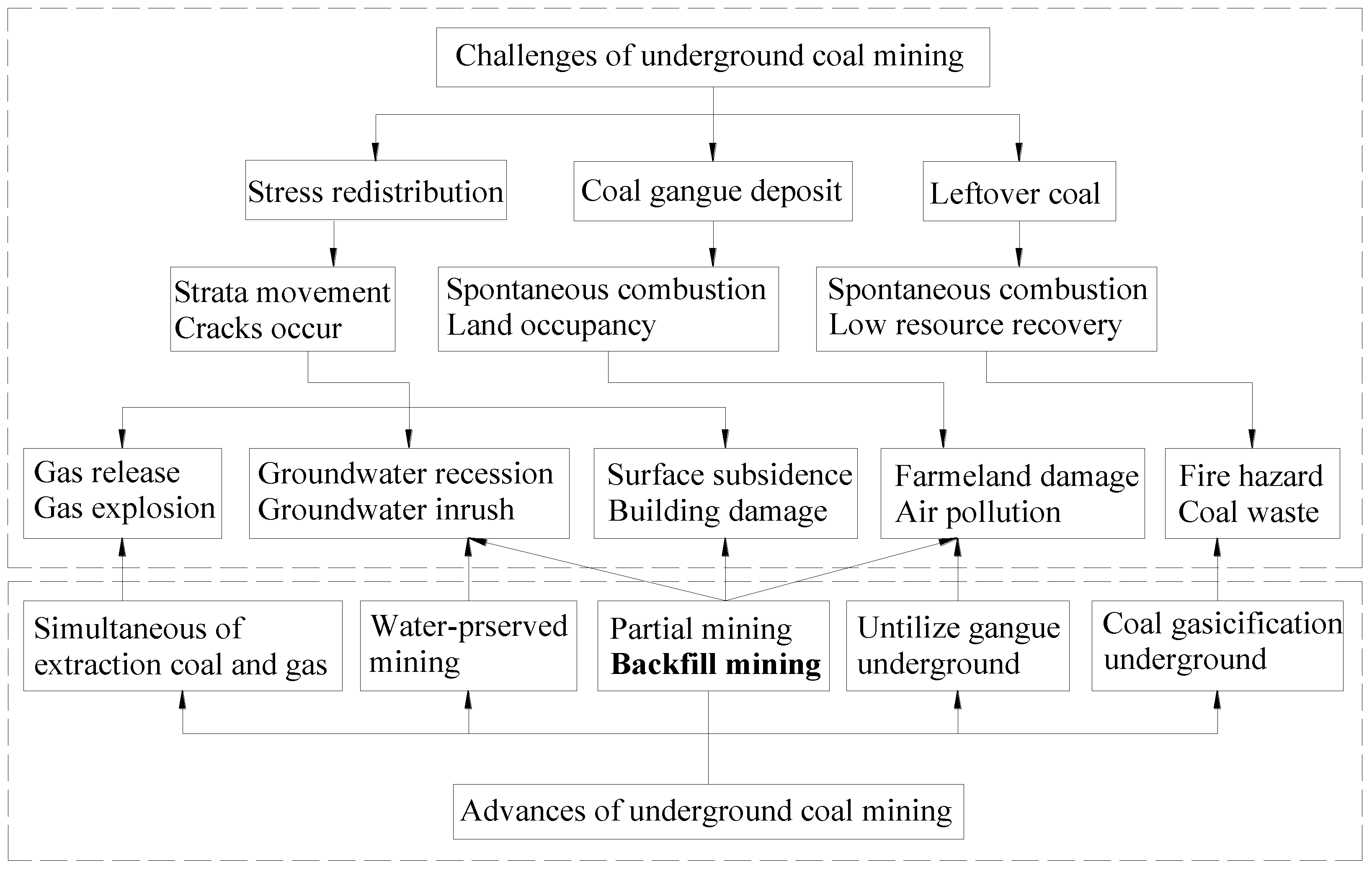
:1. Introduction
2. Water-Involving Backfill Material
2.1. Hydraulic Backfill Material
2.1.1. Preparation of Hydraulic Backfill Material
2.1.2. Transportation of Hydraulic Backfill Material
2.1.3. Activation of Hydraulic Backfill Material
2.1.4. Time Needed to Fill the Post-Mining Space with Hydraulic Backfill Material
2.1.5. Evaluation of Hydraulic Backfill Material
2.2. Cemented Backfill Material
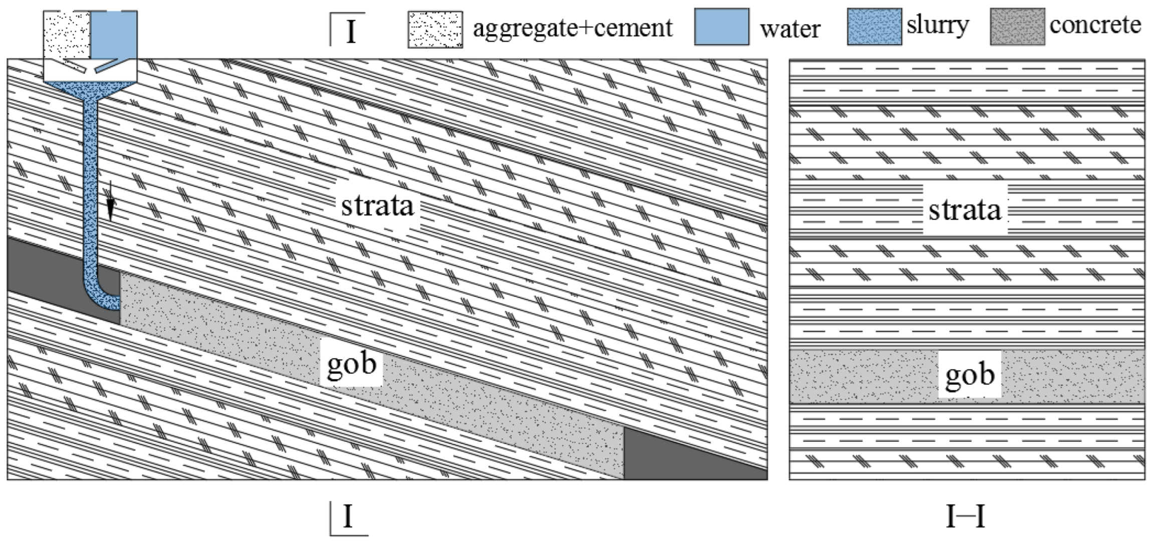
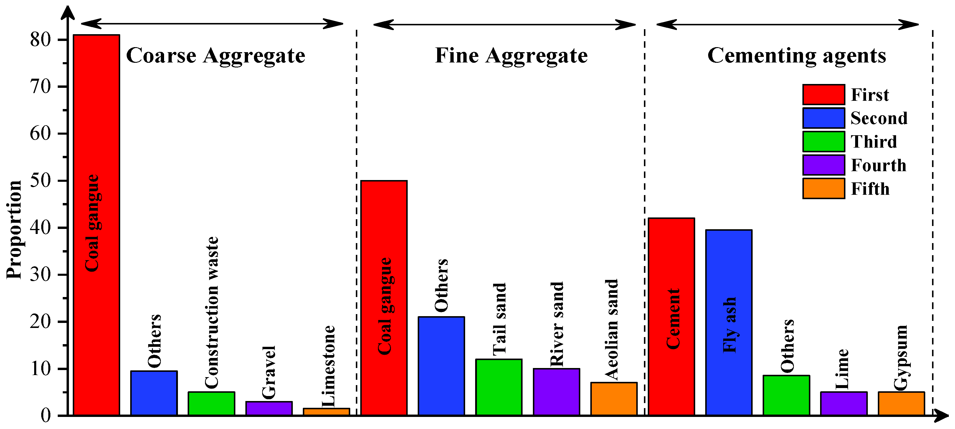
2.2.1. Preparation of Cemented Backfill Material
2.2.2. Transportation of Cemented Backfill Material
2.2.3. Activation of the Cemented Backfill Material
- (1)
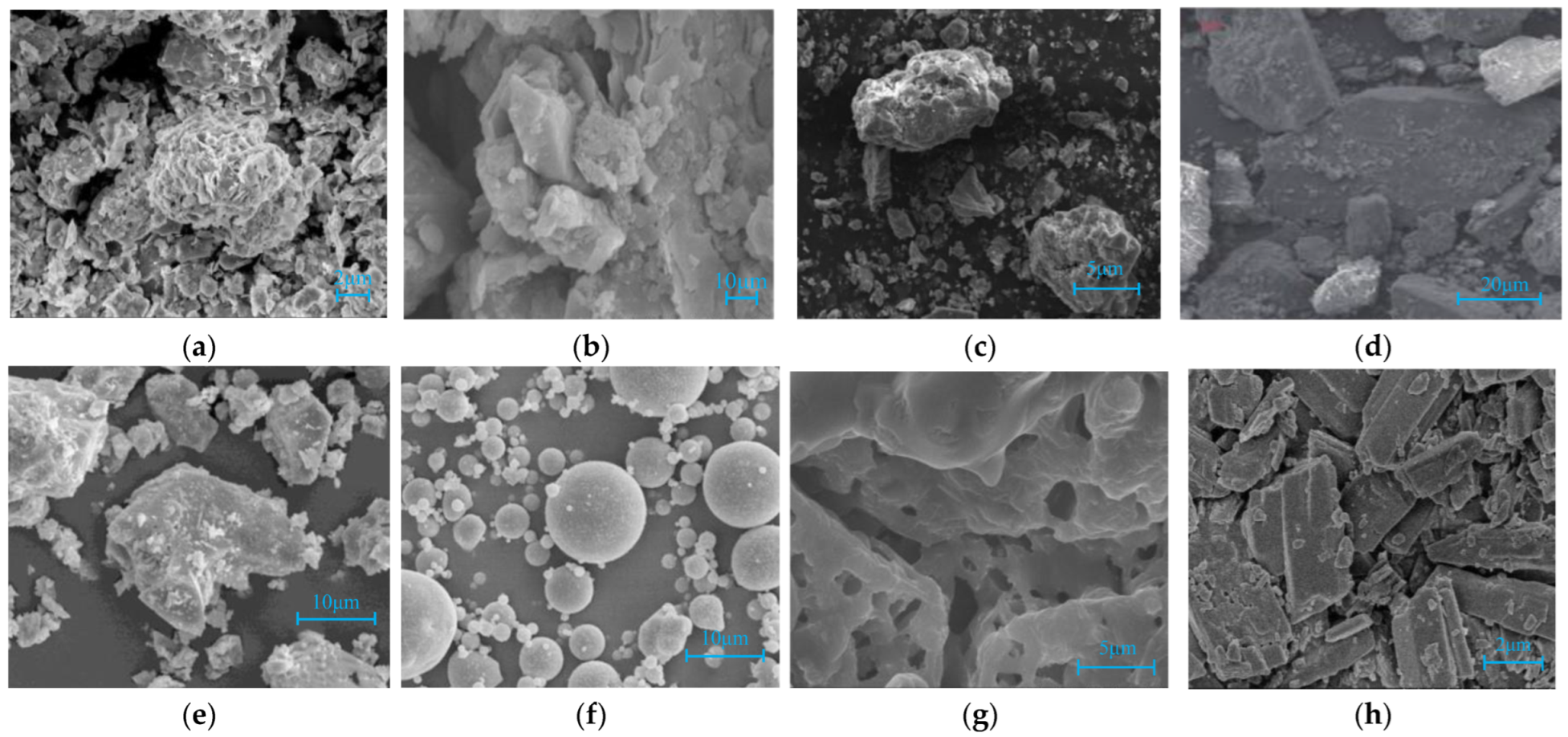
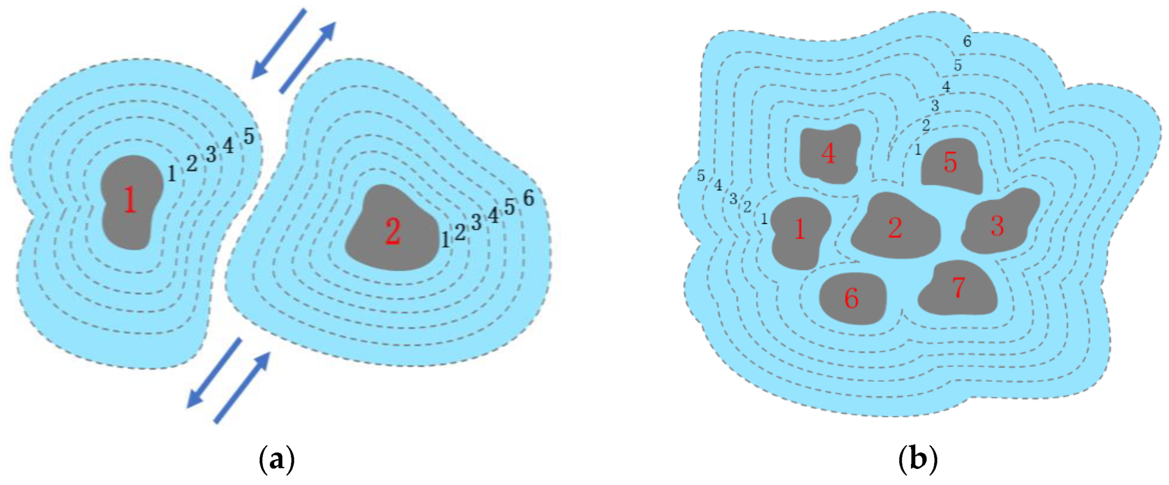
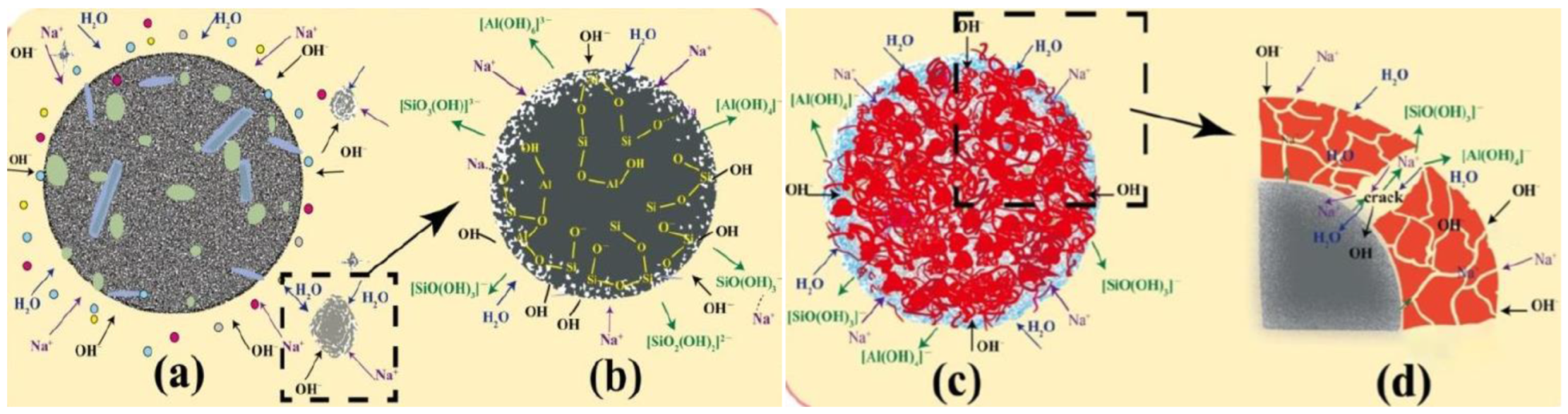
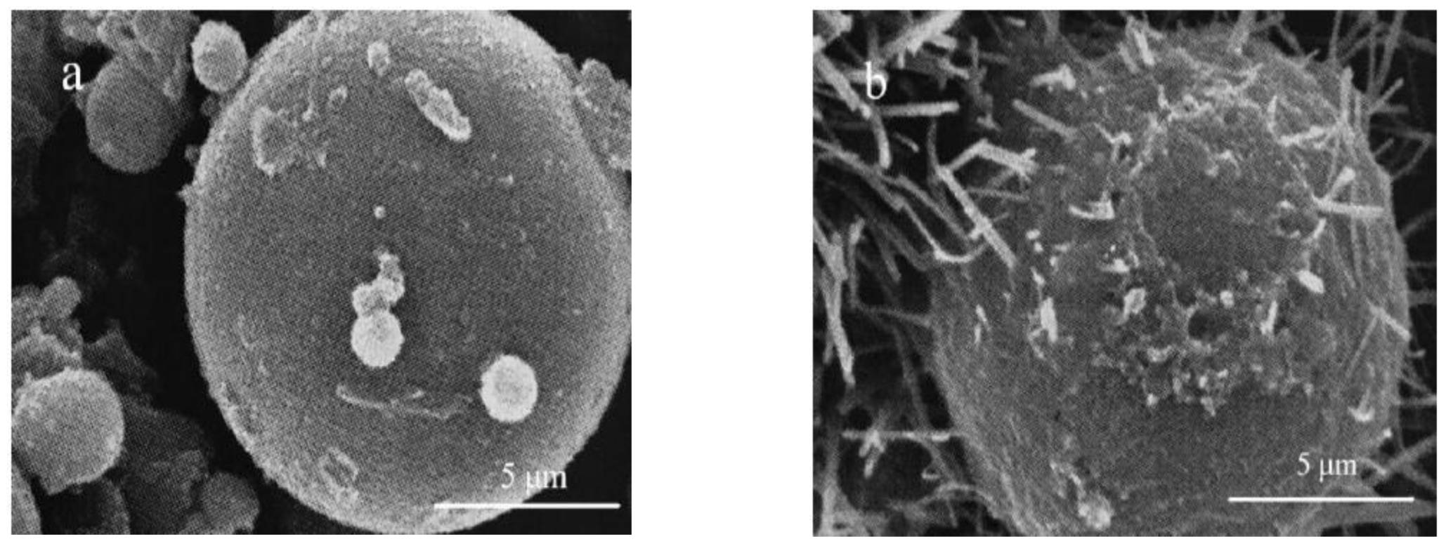
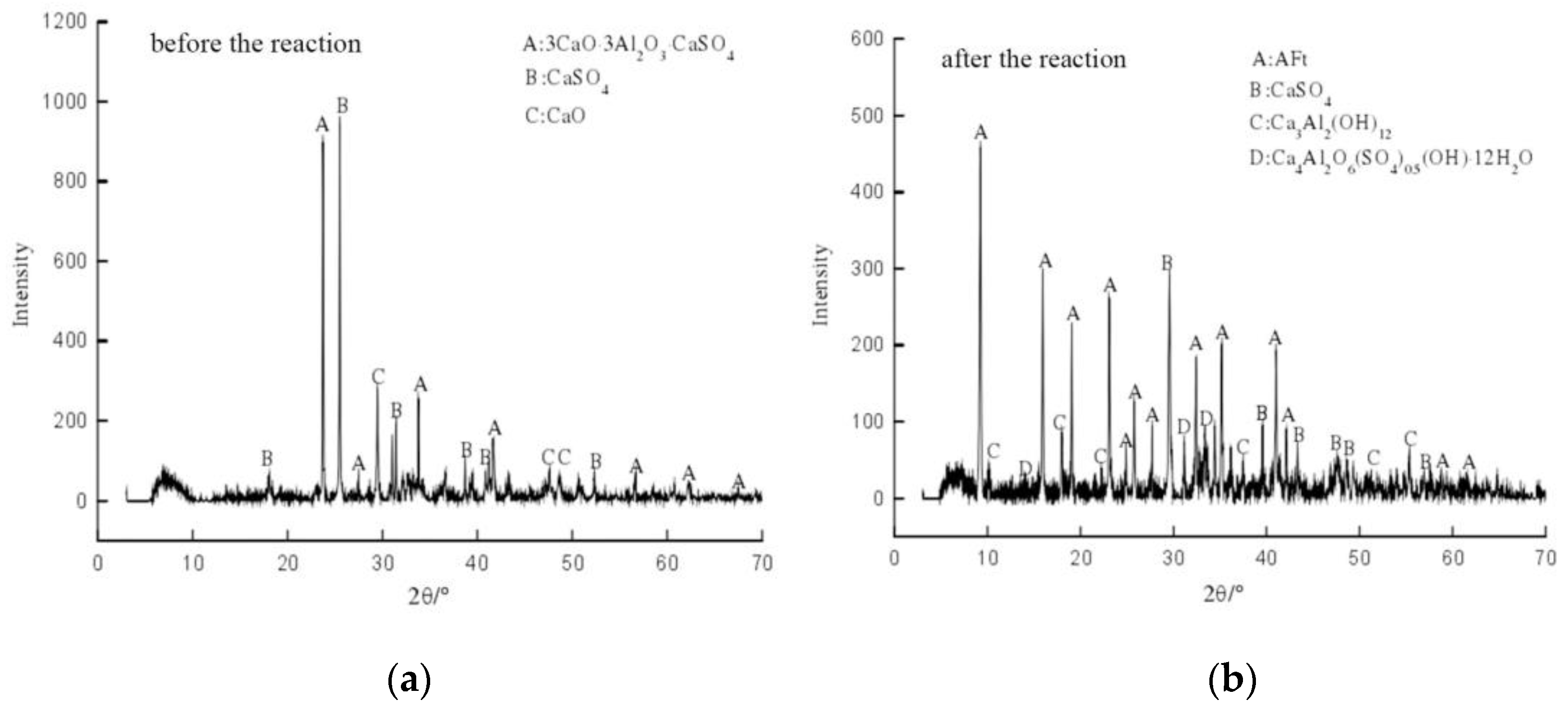
- Alkaline chemical excitation: Fly ash is mainly composed of acid oxides, and its pH value is less than seven, showing weak acidity. SiO2 is an acidic oxide, Al2O3 is an amphoteric oxide; they can react with OH− in alkaline aqueous solution so that the Si-O-Si bond, Al-O-Al bond and Si-O-Al bond are broken. After the stable vitreous networks are depolymerized, the active ingredients are in a free state, and unsaturated chemical bonds with high activity are formed. A chemical reaction occurs after mixing with cement and lime to form carburized body substances, such as calcium silicate hydrate (C-S-H), calcium aluminate hydrate (C-A-H), calcium silicate aluminate hydrate (C-A-S-H) and ettringite (Aft). The hydration products are cross-connected on the surface of fly ash glass beads to improve the mechanical strength of cemented filling materials after solidification.
- (2)
- Sulfate chemical excitation: The activated Al2O3 in fly ash reacts with Ca(OH)2 released by the hydration of cement material and SO24− ions released by the dissolution of gypsum to generate ettringite and produce a gel phenomenon, which is called sulfate excitation of fly ash activity. When CaO, Ca(OH)2 and other “calcium supplement” substances are added to the solution, the solution will contain a large amount of OH−. The potential (Al2O3) active substance in fly ash is firstly reacted with OH− to form AlO2− and then reacts with Ca2+ and SO42− to generate ettringite (AFt) with a certain gelation. The reactions are shown in Equations (25) and (26). The common sulfate activators are Na2SO4, K2SO4 and CaSO4. For example, Na2SO4 is easily soluble in water and can react with Ca(OH)2 in solution and produce relatively dispersed CaSO4, which more easily produces calcium–vanadite than gypsum. Na2SO4 can also react with Ca(OH)2 in the solution to form NaOH, which increases the alkalinity of the solution. So, the excitation of Na2SO4 is actually a double excitation of a strong base and sulfate.
2.2.4. Time Needed to Fill the Post-Mining Space with Cemented Backfill Material
2.2.5. Evaluation of the Cemented Backfill Material
2.3. High-Water Backfill Material
2.3.1. Preparation of High-Water Backfill Material
2.3.2. Transportation of the High-Water Backfill Material
2.3.3. Activation of the High-Water Backfill Material
2.3.4. Time Needed to Fill the Post-Mining Space with High-Water Backfill Material
2.3.5. Evaluation of the High-Water Backfill Material
3. Waterless Backfill Material
3.1. Gangue Backfilling Material
3.1.1. Preparation of the Gangue Backfill Material
3.1.2. Transportation of the Gangue Backfilling Material
3.1.3. Activation of the Gangue Backfilling Material
3.1.4. Time Needed to Fill the Post-Mining Space with Gangue Backfill Material
3.1.5. Evaluation of Gangue Backfilling Material
4. Expectation of Backfilling Material Selection in China
5. Conclusions
6. Patents
Author Contributions
Funding
Data Availability Statement
Acknowledgments
Conflicts of Interest
References
- Qi, H.Y. Analysis on production status and safety situation for developed country of coal industry. China Coal 2015, 41, 140–143. [Google Scholar]
- Zhang, Z.Y.; Shimada, H.; Sasaoka, T.; Hamanaka, A. Stability Control of Retained Goaf-Side Gateroad under Different Roof Conditions in Deep Underground Y Type Longwall Mining. Sustainability 2017, 9, 1671. [Google Scholar] [CrossRef] [Green Version]
- Liu, X.; Jing, M.; Bai, Z. Heavy Metal Concentrations of Soil, Rock, and Coal Gangue in the Geological Profile of a Large Open-Pit Coal Mine in China. Sustainability 2022, 14, 1020. [Google Scholar] [CrossRef]
- Hao, Y.; Xie, T. Oxidation Behavior and Kinetics Parameters of a Lean Coal at Low Temperature Based on Different Oxygen Concentrations. Minerals 2021, 11, 511. [Google Scholar] [CrossRef]
- Qu, Q.; Guo, H.; Yuan, L.; Shen, B.; Yu, G.; Qin, J. Rock Mass and Pore Fluid Response in Deep Mining: A Field Monitoring Study at Inclined Longwalls. Minerals 2022, 12, 463. [Google Scholar] [CrossRef]
- Qian, M.G.; Xu, J.L.; Miao, X.X. Green Technique in Coal Mining. J. China Univ. Min. Technol. 2003, 04, 5–10. [Google Scholar]
- Rajwa, S.; Janoszek, T.; Świątek, J.; Walentek, A.; Bałaga, D. Numerical Simulation of the Impact of Unmined Longwall Panel on the Working Stability of a Longwall Using UDEC 2D—A Case Study. Energies 2022, 15, 1803. [Google Scholar] [CrossRef]
- Zhang, Z.Y.; Liu, H.; Su, H.; Zeng, Q. Green Mining Takes Place at the Power Plant. Minerals 2022, 12, 839. [Google Scholar] [CrossRef]
- Xie, S.; Guo, F.; Wu, Y. Control Techniques for Gob-Side Entry Driving in an Extra-Thick Coal Seam with the Influence of Upper Residual Coal Pillar: A Case Study. Energies 2022, 15, 3620. [Google Scholar] [CrossRef]
- Wang, X.; Zhang, J.; Li, M.; Gao, F.; Taheri, A.; Huo, B.; Jin, L. Expansion Properties of Cemented Foam Backfill Utilizing Coal Gangue and Fly Ash. Minerals 2022, 12, 763. [Google Scholar] [CrossRef]
- Korzeniowski, W.; Poborska Mlynarska, K.; Skrzypkowski, K. The idea of the recovery of Municipal Solid Waste Incineration (MSWI) residues in Klodawa salt mine S.A. by filling the excavations with self-solidifying mixtures. Arch. Min. Sci. 2018, 63, 3. [Google Scholar]
- Skrzypkowski, K. Compressibility of materials and backfilling mixtures with addition of solid wastes from flue-gas treatment and fly ashes. E3S Web Conf. 2018, 71, 7. [Google Scholar] [CrossRef]
- Ajayi, S.A.; Ma, L.; Spearing, A.J.S. Ground Stress Analysis and Automation of Workface in Continuous Mining Continuous Backfill Operation. Minerals 2022, 12, 754. [Google Scholar] [CrossRef]
- Cao, H.; Gao, Q.; Zhang, X.; Guo, B. Research Progress and Development Direction of Filling Cementing Materials for Filling Mining in Iron Mines of China. Gels 2022, 8, 192. [Google Scholar] [CrossRef]
- Wu, C.; Zhang, Y.; Zhang, J.; Chen, Y.; Duan, C.; Qi, J.; Cheng, Z.; Pan, Z. Comprehensive Evaluation of the Eco-Geological Environment in the Concentrated Mining Area of Mineral Resources. Sustainability 2022, 14, 6808. [Google Scholar] [CrossRef]
- Liu, J.; Ma, F.; Guo, J.; Li, G.; Song, Y.; Wang, Y. A Field Study on the Law of Spatiotemporal Development of Rock Movement of Under-Sea Mining, Shandong, China. Sustainability 2022, 14, 5864. [Google Scholar] [CrossRef]
- Adach-Pawelus, K.; Pawelus, D. Application of Hydraulic Backfill for Rockburst Prevention in the Mining Field with Remnant in the Polish Underground Copper Mines. Energies 2021, 14, 3869. [Google Scholar] [CrossRef]
- Li, L.; Huang, Q.; Zuo, X.; Wu, J.; Wei, B.; He, Y.; Zhang, W.; Zhang, J. Study on the Slurry Diffusion Law of Fluidized Filling Gangue in the Caving Goaf of Thick Coal Seam Fully Mechanized Caving Mining. Energies 2022, 15, 8164. [Google Scholar] [CrossRef]
- Xu, G.G.; Wang, X.D.; Wang, H.; Shao, H.Q.; Cao, Z.B. Treatment technology of cavitary gob area based on high concentration cemented filling material. Coal Eng. 2021, 53, 73–80. [Google Scholar]
- Skrzypkowski, K. Determination of the Backfilling Time for the Zinc and Lead Ore Deposits with Application of the BackfillCAD Model. Energies 2021, 14, 3186. [Google Scholar] [CrossRef]
- Xu, W.B.; Du, J.H.; Song, W.D.; Chen, H.Y. Experiment on the mechanism of consolidating backfill body of extra-fine grain unclassified tailings and cementitious materials. Rock Soil Mech. 2013, 34, 2295–2302. [Google Scholar]
- Jia, Z.G. Experimental study on failure characteristics of strata with different filling rates in longwall filling mining. Coal Sci. Technol. 2019, 47, 197–202. [Google Scholar]
- Wei, X.M.; Guo, S.J.; Li, Z.N. Study on the strength difference of cemented backfill based on macro-micro coupling analysis. China Min. Mag. 2018, 27, 95–99. [Google Scholar]
- Yu, W.J.; Wan, X.; Liu, F.F.; Wang, Z. Experimental study on red clay paste backfilling material and its physical characteristics. Coal Sci. Technol. 2021, 49, 61–68. [Google Scholar]
- Li, M.H.; Yang, Z.Q.; Wang, Y.T.; Gao, Q. Experiment study of compressive strength and mechanical property of filling body for fly ash composite cementitious materials. J. China Univ. Min. Technol. 2015, 44, 650–655. [Google Scholar]
- Feng, G.M.; Ding, Y.; Zhu, H.J. Bai Jianbiao Experimental study on mining ultra-high water filling material and its structure. J. China Univ. Min. Technol. 2010, 39, 813–819. [Google Scholar]
- Zhou, G.M.; Ma, Y.D.; Li, X.T. Study on compression deformation characteristics of high solid water filling materials with different water content. J. Jiangsu Constr. Vocat. Tech. Coll. 2019, 19, 1–6. [Google Scholar]
- Amin, M.N.; Iqbal, M.; Ashfaq, M.; Salami, B.A.; Khan, K.; Faraz, M.I.; Alabdullah, A.A.; Jalal, F.E. Prediction of Strength and CBR Characteristics of Chemically Stabilized Coal Gangue: ANN and Random Forest Tree Approach. Materials 2022, 15, 4330. [Google Scholar] [CrossRef]
- Zhao, Y.S.; Du, X.L.; Dang, P.; Liu, G.J. Design on High-Concentration Cemented Filling Station in Xinyang Coal Mine. Coal Eng. 2014, 46, 31–33. [Google Scholar]
- Wen, P.; Guo, W.; Tan, Y.; Bai, E.; Ma, Z.; Wu, D.; Yang, W. Paste Backfilling Longwall Mining Technology for Thick Coal Seam Extraction under Buildings and above Confined Aquifers: A Case Study. Minerals 2022, 12, 470. [Google Scholar] [CrossRef]
- Wang, X.M.; Ding, D.Q.; Wu, Y.B.; Zhang, Q.L.; Lu, Y.Z. Numerical simulation and analysis of paste backfilling with piping transport. China Min. Mag. 2006, 07, 57–59+66. [Google Scholar]
- Zhao, C.Z.; Zhou, H.Q.; Bai, J.B.; Qiang, H. Influence factor analysis of paste filling material strength. J. Liaoning Tech. Univ. 2006, 25, 904–906. [Google Scholar]
- Zhao, C.Z.; Zhou, H.Q.; Qu, Q.D.; Chang, Q.L. Experimental study on rheology performances of paste backfilling slurry. Coal Sci. Technol. 2006, 34, 54–56. [Google Scholar]
- Luan, H.; Jiang, Y.; Lin, H.; Wang, Y. A New Thin Seam Backfill Mining Technology and Its Application. Energies 2017, 10, 2023. [Google Scholar] [CrossRef] [Green Version]
- Cheng, Q.; Guo, Y.; Dong, C.; Xu, J.; Lai, W.; Du, B. Mechanical Properties of Clay Based Cemented Paste Backfill for Coal Recovery from Deep Mines. Energies 2021, 14, 5764. [Google Scholar] [CrossRef]
- Lv, W.; Guo, K.; Wang, H.; Feng, K.; Jia, D. Evolution Characteristics of Overlying Strata Fractures in Paste Composite Filling Stope. Minerals 2022, 12, 654. [Google Scholar] [CrossRef]
- Yin, B.; Kang, T.; Kang, J.; Chen, Y. Experimental and Mechanistic Research on Enhancing the Strength and Deformation Characteristics of Fly-Ash-Cemented Filling Materials Modified by Electrochemical Treatment. Energy Fuels 2018, 32, 3614–3626. [Google Scholar] [CrossRef]
- Xu, Y.; Ma, L.; NGO, I.; Zhai, J. Continuous Extraction and Continuous Backfill Mining Method Using Carbon Dioxide Mineralized Filling Body to Preserve Shallow Water in Northwest China. Energies 2022, 15, 3614. [Google Scholar] [CrossRef]
- Zhang, W.; Yan, C.; Zhou, G.; Guo, J.; Chen, Y.; Zhang, B.; Wu, S. Experimental and Analytical Investigation into the Synergistic Mechanism and Failure Characteristics of the Backfill-Red Sandstone Combination. Minerals 2022, 12, 202. [Google Scholar] [CrossRef]
- Rong, K.; Lan, W.; Li, H. Industrial Experiment of Goaf Filling Using the Filling Materials Based on Hemihydrate Phosphogypsum. Minerals 2020, 10, 324. [Google Scholar] [CrossRef] [Green Version]
- Wu, J.; Feng, M.; Xu, J.; Qiu, P.; Wang, Y.; Han, G. Particle Size Distribution of Cemented Rockfill Effects on Strata Stability in Filling Mining. Minerals 2018, 8, 407. [Google Scholar] [CrossRef] [Green Version]
- Yu, L.; Xia, J.; Gu, J.; Zhang, S.; Zhou, Y. Degradation Mechanism of Coal Gangue Concrete Suffering from Sulfate Attack in the Mine Environment. Materials 2023, 16, 1234. [Google Scholar] [CrossRef]
- Leng, Q.; Chang, Q.; Sun, Y.; Zhang, B.; Qin, J. The Mechanical Properties of Gangue Paste Material for Deep Mines: An Experimental and Model Study. Materials 2022, 15, 5904. [Google Scholar] [CrossRef]
- Liu, X.H.; Cui, S.L.; Zhao, J.L.; Tian, L.T.; Chen, L.; Zhao, T.Y. Top coal caving longwall mining in high coal seams under Yuecheng Reservoir: An engineering practice. China Coal 2009, 35, 66–67+87. [Google Scholar]
- Zhao, C.Z.; Zhou, H.Q.; Bai, J.B.; Chang, Q.L. Experimental Research on Fly Ash Total Tailing Paste Filling. Met. Mine 2006, 12, 4–6. [Google Scholar]
- Wang, X.; Zhang, J.; Li, M.; Huo, B.; Jin, L. Experimental Study on Performance Optimization of Grouting Backfill Material Based on Mechanically Ground Coal Gangue Utilizing Urea and Quicklime. Materials 2023, 16, 1097. [Google Scholar] [CrossRef] [PubMed]
- Guo, Z.H.; Zhou, H.Q.; Wu, L.F.; Li, F. Numerical Simulation for Roof and Surface Subsidence Process Caused by Paste Filling. J. Min. Saf. Eng. 2008, 25, 172–175. [Google Scholar]
- Sun, Q.; Zhang, X.D.; Yang, Y. Creep constitutive model of cemented body used in backfilling mining. J. China Coal Soc. 2013, 38, 994–1000. [Google Scholar]
- Yang, Z.; Wang, Q.Y.; Wang, N.; Cao, Q.H.; Ma, C.Y. Research on the “eggshell” phenomenon of the backfilling materials with cement fly ash and waste rocks. J. Qingdao Technol. Univ. 2012, 33, 49–53. [Google Scholar]
- Zheng, S.C.; Yu, Q.; Ning, P.; Ma, J.B.; Tian, L.; Zheng, Y.L. Effects and mechanism of anhydrite AⅢ on the performance ofβ-hemihydrate gypsum. J. Civ. Archit. Environ. Eng. 2015, 37, 118–124. [Google Scholar]
- Liu, Y.; Chen, J. Research status and development trend of high sand filing materials. Key Eng. Mater. 2017, 727, 1079–1083. [Google Scholar] [CrossRef]
- Li, J.S. Influence of early strength agent on strength development of cemented backfill material. Non Ferr. Metals 2000, 5, 18–19. [Google Scholar]
- Zhou, N.; Ma, H.; Ouyang, S.; Germain, D.; Hou, T. Influential Factors in Transportation and Mechanical Properties of Aeolian Sand-Based Cemented Filling Material. Minerals 2019, 9, 116. [Google Scholar] [CrossRef] [Green Version]
- Shao, X.; Tian, C.; Li, C.; Fang, Z.; Zhao, B.; Xu, B.; Ning, J.; Li, L.; Tang, R. The Experimental Investigation on Mechanics and Damage Characteristics of the Aeolian Sand Paste-like Backfill Materials Based on Acoustic Emission. Materials 2022, 15, 7235. [Google Scholar] [CrossRef]
- Wang, L.; Wang, C.L.; Sun, D.S.; Zhang, G.Z.; Wang, A.G. Experimental research on rheology characteristics of roadside support backfilling concrete. J. Anhui Inst. Archit. Ind. 2010, 18, 76–80. [Google Scholar]
- Zhang, X.; Lin, J.; Liu, J.; Li, F.; Pang, Z. Investigation of Hydraulic-Mechanical Properties of Paste Backfill Containing Coal Gangue-Fly Ash and Its Application in an Underground Coal Mine. Energies 2017, 10, 1309. [Google Scholar] [CrossRef] [Green Version]
- Wang, H.; Zhao, X.; Zhou, B.; Lin, Y.; Gao, H. Performance Optimization and Characterization of Soda Residue-Fly Ash Geopolymer Paste for Goaf Backfill: Beta-Hemihydrate Gypsum Alternative to Sodium Silicate. Materials 2020, 13, 5604. [Google Scholar] [CrossRef]
- Li, H.Y. Study on Time-Dependent Changes in the Flow Properties of Cemented Coal Gangue Backfill Materials; Taiyuan University of Technology: Taiyuan, China, 2019. [Google Scholar]
- Li, F.; Yin, D.; Zhu, C.; Wang, F.; Jiang, N.; Zhang, Z. Effects of Kaolin Addition on Mechanical Properties for Cemented Coal Gangue-Fly Ash Backfill under Uniaxial Loading. Energies 2021, 14, 3693. [Google Scholar] [CrossRef]
- Sun, Q.; Wei, X.; Li, T.; Zhang, L. Strengthening Behavior of Cemented Paste Backfill Using Alkali-Activated Slag Binders and Bottom Ash Based on the Response Surface Method. Materials 2020, 13, 855. [Google Scholar] [CrossRef] [Green Version]
- Zheng, K.; Xuan, D.; Li, J. Study on Fluid–Solid Characteristics of Grouting Filling Similar-Simulation Materials. Minerals 2022, 12, 502. [Google Scholar] [CrossRef]
- Yang, B.; Wang, X.; Yin, P.; Gu, C.; Yin, X.; Yang, F.; Li, T. The Rheological Properties and Strength Characteristics of Cemented Paste Backfill with Air-Entraining Agent. Minerals 2022, 12, 1457. [Google Scholar] [CrossRef]
- Xiang, H.Q.; Yang, H.; Gong, Y.K.; Zhang, J. Phosphate Removal in Wastewater Treatment Using Property-modified Fly Ash. Environ. Sci. Technol. 2005, 5, 18–20. [Google Scholar]
- Jia, L.T. Properties and Modification of Coal Fly Ash. Power Gener. Air Cond. 2017, 38, 35–38. [Google Scholar]
- Qin, H.Y.; Ti, Z.Y.; Zhang, F.; Wang, H.D.; Ouyang, Z.H.; Li, X.B.; Peng, R. Determination of Equivalent Mining Height in Paste-like Filling Mining. Coal Technol. 2020, 39, 1–3. [Google Scholar]
- Fu, X.L.; Peng, Y.H.; Li, D.; Cheng, K. Research on impact of water reducing agent for cemented tailing fill slurry conveying property. Coal Sci. Technol. 2017, 45, 55–60. [Google Scholar]
- Yao, Z.Q.; Zhang, Q.L.; Wang, X.M. Application of water reducing agent in paste like cemented filling. Saf. Coal Mines 2009, 40, 43–45. [Google Scholar]
- Liu, J. Application Status and Development of Filling Mining Method. Mod. Chem. Res. 2020, 7, 8–9. [Google Scholar]
- Wang, X.M.; Lu, Y.Z.; Zhang, Q.L. Simulating and Optimizing the Configuration Parameter of Stope in Plaster -Like Filling. Chin. J. Undergr. Space Eng. 2008, 4, 346–350. [Google Scholar]
- Polish Standard PN-EN 196-3; Cement Test Methods-Part 3: Determination of Setting Times and Volume Stability. Polish Committee for Standardization: Warsaw, Poland, 2006; p. 13.
- Qi, C.; Guo, L.; Wu, Y.; Zhang, Q.; Chen, Q. Stability Evaluation of Layered Backfill Considering Filling Interval, Backfill Strength and Creep Behavior. Minerals 2022, 12, 271. [Google Scholar] [CrossRef]
- Skrzypkowski, K. 3D Numerical Modelling of the Application of Cemented Paste Backfill on Displacements around Strip Excavations. Energies 2021, 14, 7750. [Google Scholar] [CrossRef]
- Zuo, Y.F.; Wang, D.M.; Gao, Z.G.; Guo, Q.; Mei, S.G.; Liu, J.L. Effect of chemical structure and composition of polycarboxylate superplasticizer on cement hydration. New Build. Mater. 2016, 43, 25–29+42. [Google Scholar]
- Zhao, Y. Research on Red-Mud Based Cementitious Paste Goaf Backfill Materials and Its Environmental Performances; Taiyuan University of Technology: Taiyuan, China, 2021. [Google Scholar] [CrossRef]
- Zhang, J.; Li, M.; Taheri, A.; Zhang, W.; Wu, Z.; Song, W. Properties and Application of Backfill Materials in Coal Mines in China. Minerals 2019, 9, 53. [Google Scholar] [CrossRef] [Green Version]
- Wang, X.; Qin, D.; Zhang, D.; Sun, C.; Zhang, C.; Xu, M.; Li, B. Mechanical Characteristics of Superhigh-Water Content Material Concretion and Its Application in Longwall Backfilling. Energies 2017, 10, 1592. [Google Scholar] [CrossRef] [Green Version]
- Ding, Y.; Feng, G.M.; Wang, Z.C. Experimental study on basic properties of ultra-high water filling materials. J. Coal 2011, 36, 1087–1092. [Google Scholar]
- Zhou, X.; Xu, H.B.; Liu, J.H. Study on instability failure characteristics and performance improvement of high water filling materials. J. Coal 2017, 42, 1123–1129. [Google Scholar]
- Zhang, H.X.; Zhou, H.B.; Chen, F.Y.; Fen, T.; Sheng, S.H.; Wu, Z.G. research on Tianjin industry’s energy-short-age alleviation based on GFI model. J. Saf. Environ. 2015, 15, 295–299. [Google Scholar]
- Peng, M.X.; Jiang, J.H.; Wang, Z.H.; Shen, S.H. Study on preparation, microstructure and curing mechanism of slurry solidified filling material. Silic. Bull. 2011, 30, 1294–1298. [Google Scholar]
- Yu, L.M.; Wang, F.G.; Wang, J.; Lan, W.T. Study on fluidity of high water swelling material slurry. Gansu Metall. 2013, 35, 1–4+16. [Google Scholar]
- Xie, S.R.; Zhang, G.C.; He, S.S.; Sun, Y.J. Surrounding rock control mechanism and application of gob retaining roadway in deep large mining height filling mining. J. Coal 2014, 39, 2362–2368. [Google Scholar]
- Li, J.; Feng, G.M.; Jia, K.J.; Zhou, S.; Yao, F. Application Research on filling mining with ultra-high water material and retaining roadway along goaf. Coal Eng. 2013, 45, 10–12. [Google Scholar]
- Hua, H.T. Study on Roadway Side Filling and Gob Side Retaining Technology of New High Water Material in High Dip Thin Coal Seam; China University of Mining and Technology: Beijing, China, 2015. [Google Scholar]
- Bai, J.B.; Hou, C.J.; Zhang, C.G.; Yang, T.M.; Zhang, D.G.; Niu, H.W. Industrial test of filling empty roadway with high water content material. Coal Sci. Technol. 2000, 30–31+39. [Google Scholar] [CrossRef]
- Li, X.F.; Xiong, Z.Q.; Wang, X.; Sun, Y.P.; Jiang, T. Ultra high water material ratio and filling process optimization in filling mining of thin coal seam. Coal Mine Saf. 2020, 51, 162–167. [Google Scholar]
- Gao, Y.G.; Ma, Q. Application Research of high water material gob side entry retaining technology in Yunjialing 12303 working face. Coal Chem. Ind. 2015, 38, 42–44+152. [Google Scholar]
- Huang, P.; Spearing, S.; Ju, F.; Jessu, K.V.; Wang, Z.; Ning, P. Control Effects of Five Common Solid Waste Backfilling Materials on In Situ Strata of Gob. Energies 2019, 12, 154. [Google Scholar] [CrossRef] [Green Version]
- Gu, W.; Chen, L.; Xu, D. Research on the Overburden Movement Law of Thick Coal Seam Without-Support Gangue-Filling Mining. Minerals 2023, 13, 53. [Google Scholar] [CrossRef]
- Wang, S.; Lv, W.; Zhang, W.; Fan, J.; Luo, A.; Zhu, K.; Guo, K. Scale Effect of Filling on Overburden Migration in Local Filling Stope of Longwall Face in Steeply Dipping Coal Seam. Minerals 2022, 12, 319. [Google Scholar] [CrossRef]
- Zhang, S.; Che, C.; Zhao, C.; Du, S.; Liu, Y.; Li, J.; Yang, S. Effect of Fly Ash and Steel Fiber Content on Workability and Mechanical Properties of Roadway Side Backfilling Materials in Deep Mine. Energies 2023, 16, 1505. [Google Scholar] [CrossRef]
- Guo, G.L.; Miao, X.X.; Cha, J.F.; Ma, Z.G.; Zhou, Z.Y. Preliminary analysis on subsidence control effect of gangue filling mining in long wall face. China Sci. Technol. Pap. Online 2008, 11, 805–809. [Google Scholar]
- Zhang, J.X.; Miao, X.X.; Guo, G.L. Development status of gangue (solid waste) direct filling coal mining technology. J. Min. Saf. Eng. 2009, 26, 395–401. [Google Scholar]
- Ti, Z.Y.; Qin, H.Y.; Li, S.X. Experimental analysis on compaction characteristics of gangue filling. J. Water Resour. Water Eng. 2012, 23, 129–131. [Google Scholar]
- Yang, Y.; Wang, B.F.; Zheng, Z.M. Experimental study on compaction energy consumption characteristics of coal mine gangue filling material. Silic. Bull. 2016, 35, 3511–3516. [Google Scholar]
- Cui, J.K.; Zhang, H.; Li, Z.Y.; Luo, F.; Guo, L.J.; Wang, K. Comparative experimental study on compaction characteristics of gangue and fly ash. Coal Technol. 2017, 36, 284–287. [Google Scholar]
- Geng, Q.Y.; Yao, S.Y.; Zhang, P.F.; Li, Z.H.; Liu, X.M. Analysis on Influencing Factors of overburden deformation monitoring and control effect in filling mining. China Coal 2018, 44, 46–49. [Google Scholar]
- Han, X.L. Study on Mechanical Response of Bulk Filling Material under Compaction; China University of Mining and Technology: Beijing, China, 2017. [Google Scholar]
- Li, M.; Zhang, J.X.; Miao, X.X.; Huang, Y.L. Study on the movement law of rock formation under the compaction characteristics of solid filling. J. China Univ. Min. Technol. 2014, 43, 969–973+980. [Google Scholar]
- Li, J.; Huang, Y.; Chen, Z.; Li, M.; Qiao, M.; Kizil, M. Particle-Crushing Characteristics and Acoustic-Emission Patterns of Crushing Gangue Backfilling Material under Cyclic Loading. Minerals 2018, 8, 244. [Google Scholar] [CrossRef] [Green Version]
- Qin, T.; Guo, X.; Huang, Y.; Wu, Z.; Qi, W.; Wang, H. Study on Macro-Meso Deformation Law and Acoustic Emission Characteristics of Granular Gangue under Different Loading Rates. Minerals 2022, 12, 1422. [Google Scholar] [CrossRef]
- Yin, Y.; Zhao, T.; Zhang, Y.; Tan, Y.; Qiu, Y.; Taheri, A.; Jing, Y. An Innovative Method for Placement of Gangue Backfilling Material in Steep Underground Coal Mines. Minerals 2019, 9, 107. [Google Scholar] [CrossRef] [Green Version]
- Li, X.W.; Zhao, X.Y.; Cheng, L.C.; Qin, Y.L. Experimental study on lateral compaction characteristics of gangue backfill under limited Roof. Coal Sci. Technol. 2020, 48, 18–24. [Google Scholar]
- Xiao, M.; Ju, F.; He, Z.Q.; Li, K.Y.; Wang, P. Experimental study on Influencing Factors of side pressure coefficient of gangue filling material. J. Min. Saf. Eng. 2020, 37, 73–80. [Google Scholar]
- Ou, Y. Application of Gangue Filling Method in Upward Mining; Hunan University of Science and Technology: Xiangtan, China, 2015. [Google Scholar]
- MA, Y.D. Study on the Macro-Micro Bearing Features of Different Polymer-Gangue Filling Material; China University of Mining and Technology: Xuzhou, China, 2020. [Google Scholar] [CrossRef]
- Liu, H.F.; Zhang, J.X.; Zhou, N.; Shen, L.L.; Zhang, L.B.; Zhu, C.L.; Wang, L. Study of the leaching and solidification mechanism of heavy metals from gangue-based cemented paste backfilling materials. J. China Univ. Min. Technol. 2021, 50, 523–531. [Google Scholar]
- Guo, Y.X.; Zhao, Y.H.; Feng, G.R.; Ran, H.Y.; Zhang, Y.J. Study on damage size effect of cemented gangue backfill body under uniaxial compression. Chin. J. Rock Mech. Eng. 2021, 40, 2434–2444. [Google Scholar]
- Feng, G.R.; Xie, W.S.; Guo, Y.X.; Guo, J.; Ran, H.Y.; Zhao, Y.H. Effect of early load on mechanical properties and damage of cemented gangue backfill. Chin. J. Rock Mech. Eng. 2021, 41, 775–784. [Google Scholar]
- Zheng, B.C.; Zhou, H.Q.; He, R.J. Experimental Research on Coal Gangue Paste Filling Material. Exp. Res. Coal Gangue Paste Fill. Mater. 2006, 4, 460–463. [Google Scholar]
- Wang, S.M.; Shen, Y.J.; Sun, Q.; Liu, L.; Shi, Q.M.; Zhu, M.B.; Zhang, B.; Cui, S.D. Underground CO2 storage and technical problems in coal mining area under the “dual carbon” target. J. China Coal Soc. 2022, 47, 45–60. [Google Scholar]
- Liu, L.; Wang, S.M.; Zhu, M.B.; Zhang, H.; Hou, D.Z.; Xun, C.; Zhang, X.Y.; Wang, X.L.; Wang, M. CO2 storage-cavern construction and storage method based on functional backfill. J. China Coal Soc. 2022, 47, 1072–1086. [Google Scholar]
- Yuan, L.; Jiang, Y.D.; He, X.Q.; Dou, L.M.; Zhao, X.P.; Zhao, X.S.; Wang, K.; Yu, Q.; Lu, X.M.; Li, H.C. Research progress of precise risk accurate identification and monitoring early warning on typical dynamic disasters in coal mine. J. China Coal Soc. 2018, 43, 306–318. [Google Scholar]
- Xie, H.P.; Li, C.B.; Gao, M.Z.; Zhang, R.; Zhu, J.B. Conceptualization and preliminary research on deep in situ rock mechanics. Chin. J. Rock Mech. Eng. 2021, 40, 217–232. [Google Scholar]
- Zhang, D.S.; Li, W.P.; Lai, X.P.; Fan, G. Development on basic theory of water protection during coal mining in northwest of China. J. China Coal Soc. 2017, 42, 36–43. [Google Scholar]
- Woo, K.S.; Eberhardt, E.; Elmo, D.; Stead, D. Empirical investigation and characterization of surface subsidence related to block cave mining. Int. J. Rock Mech. Min. Sci. 2013, 61, 31–42. [Google Scholar] [CrossRef]
- Ju, J.F.; Xu, J.L. Surface stepped subsidence related to top-coal caving longwall mining of extrem-ely thick coal seam under shallow cover. Int. J. Rock Mech. Min. Sci. 2015, 78, 27–35. [Google Scholar] [CrossRef]
- Tesarik, D.R.; Seymour, J.B.; Yanske, T.R. Long-term stability of a backfilled room-and-pillar test section at the Buick Mine, Missouri, USA. Int. J. Rock Mech. Min. Sci. 2009, 46, 1182–1196. [Google Scholar] [CrossRef]
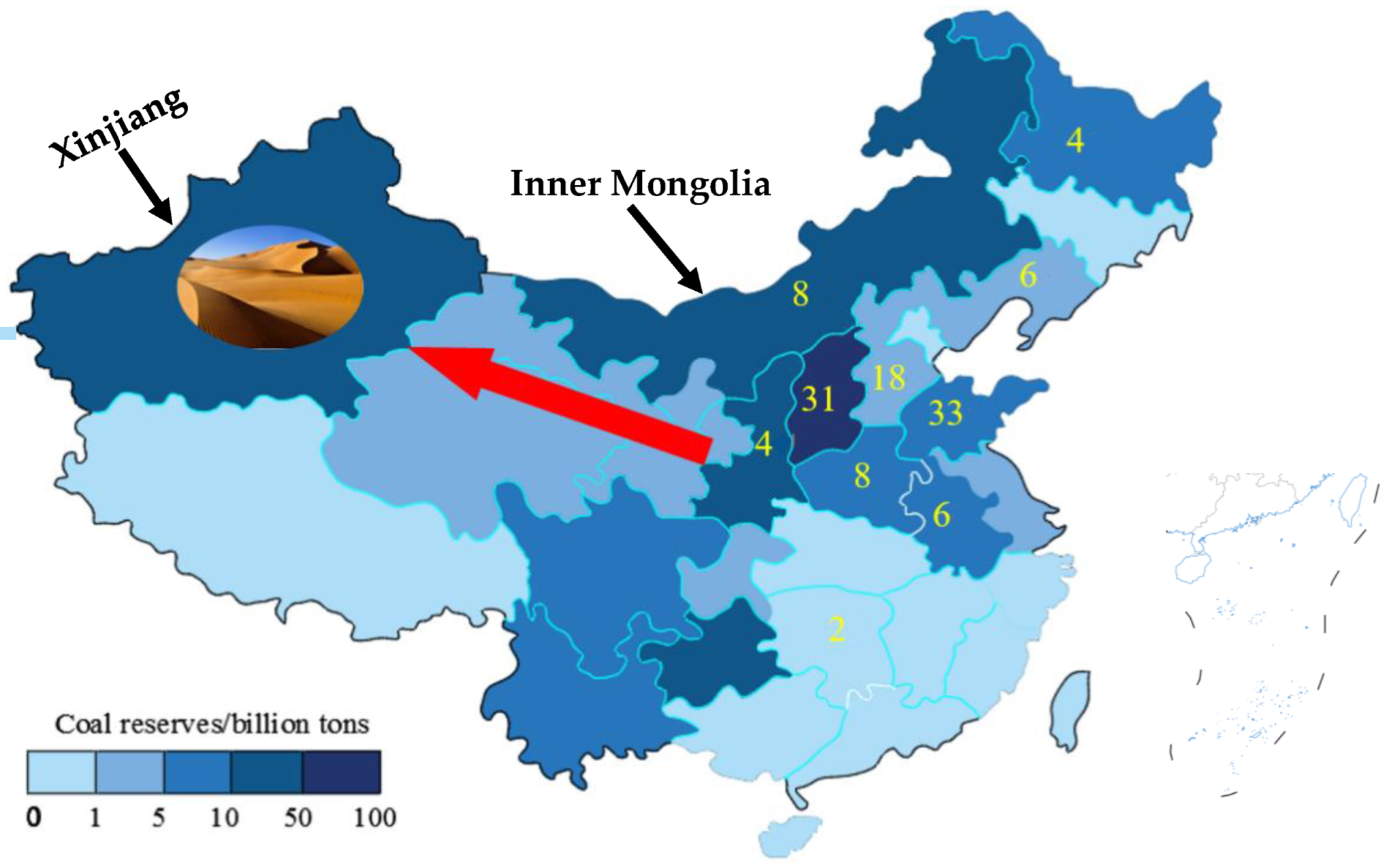
- Zeng, Q.; Li, G.S.; Dong, J.X.; Ya, P. Typical Ecological and Environmental Issues and Countermeasures in Coal Mining in Xinjiang Region. Min. Saf. Environ. Prot. 2017, 44, 106–110. [Google Scholar]
- Li, Z.Y.; Cao, Y.W.; Ling, N.X.; Mei, Y.J. Compaction Mechanism of Aeolian Sand. China J. Highw. Transp. 2006, 19, 6–11. [Google Scholar]
- Wang, X.D.; Xu, G.G.; Zhu, S.B.; Wu, B.Q.; Yuan, K.K. Rheological Properties of High Concentration Cemented Material Taking Loess and Aeolian Sand as Aggregates. Safety 2007, 48, 57–62. [Google Scholar]


| Minerals | Chemical Formula | Content (%) |
|---|---|---|
| C3S | 3CaO·SiO2 | 54 |
| C2S | 2CaO·SiO2 | 20 |
| C3A | 3CaO·Al2O3 | 7 |
| C4AF | 3CaO·Al2O3·Fe2O3 | 14 |
| CaSO4·2H2O | 3.5 |
| VII (mm) | IV (mm) | XII (mm) | IX (mm) | VI (mm) | III (mm) | II (mm) | I (mm) | Reference |
|---|---|---|---|---|---|---|---|---|
| 150~125 | 100~125 | 75~100 | 50~75 | 25~50 | 10~25 | 5~10 | 2.5~5 | [92] |
| >25 | 20~25 | l5~20 | 10~15 | 5~10 | ≤5 | [93] | ||
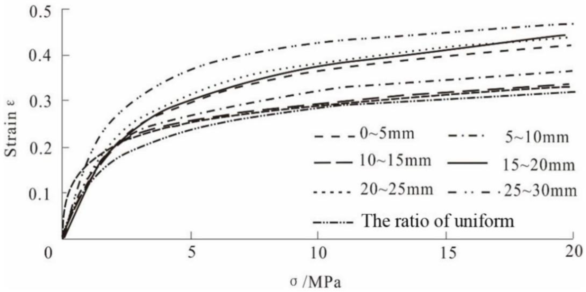
| 25~30 | 20~25 | 15~20 | 10~15 | 5~10 | 0~5 | [94] | ||
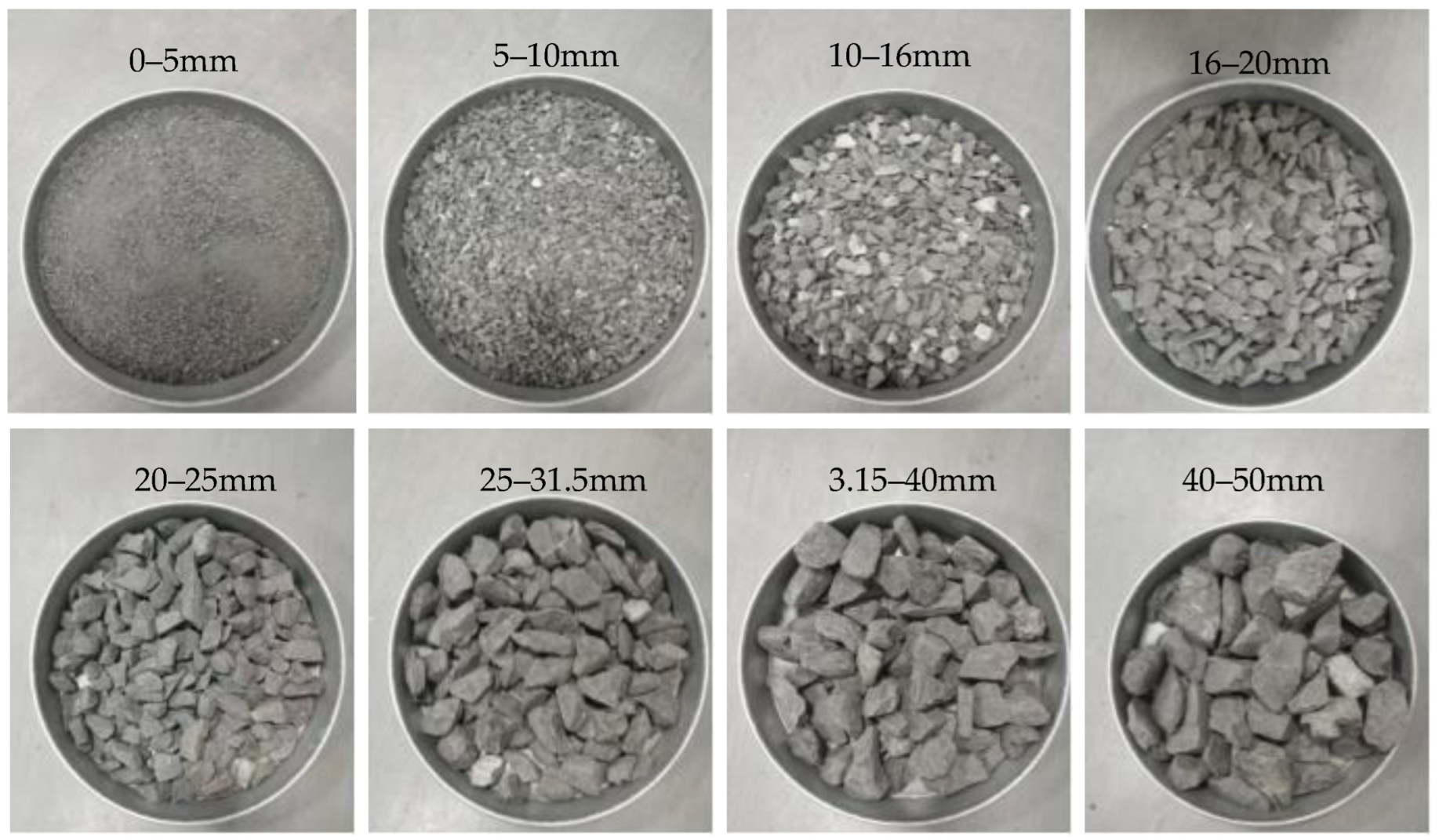
| 25~31.5 | 20~25 | 16~20 | 10~16 | 5~10 | 0~5 | [95] | ||
| 30~40 | 20~30 | 10~20 | 0~10 | [96] | ||||
| 16~20 | 9.5~16 | 5~9.5 | 2.36~5 | ≤2.36 | [97] | |||
| 40~50 | 31.5~40 | 25~31.5 | 20~25 | 16~20 | 10~16 | 5~10 | 0~5 | [98] |
| 30~40 | 20~30 | 10~20 | 0~10 | [99] | ||||
| 40~50 | 30~40 | 20~30 | 10~20 | 0~10 | [100] |
Disclaimer/Publisher’s Note: The statements, opinions and data contained in all publications are solely those of the individual author(s) and contributor(s) and not of MDPI and/or the editor(s). MDPI and/or the editor(s) disclaim responsibility for any injury to people or property resulting from any ideas, methods, instructions or products referred to in the content. |
© 2023 by the authors. Licensee MDPI, Basel, Switzerland. This article is an open access article distributed under the terms and conditions of the Creative Commons Attribution (CC BY) license (https://creativecommons.org/licenses/by/4.0/).
Share and Cite
Feng, J.; Zhang, Z.; Guan, W.; Wang, W.; Xu, X.; Song, Y.; Liu, H.; Su, H.; Zhao, B.; Hou, D. Review of the Backfill Materials in Chinese Underground Coal Mining. Minerals 2023, 13, 473. https://doi.org/10.3390/min13040473
Feng J, Zhang Z, Guan W, Wang W, Xu X, Song Y, Liu H, Su H, Zhao B, Hou D. Review of the Backfill Materials in Chinese Underground Coal Mining. Minerals. 2023; 13(4):473. https://doi.org/10.3390/min13040473
Chicago/Turabian StyleFeng, Junwen, Zhiyi Zhang, Weiming Guan, Wei Wang, Xinyi Xu, Yongze Song, Hao Liu, Hui Su, Bo Zhao, and Dazhong Hou. 2023. "Review of the Backfill Materials in Chinese Underground Coal Mining" Minerals 13, no. 4: 473. https://doi.org/10.3390/min13040473