Article

Reconstruction of the Magma Transport Patterns in the Permian-Triassic Siberian Traps from the Northwestern Siberian Platform on the Basis of Anisotropy of Magnetic Susceptibility Data

1
Schmidt Institute of the Physics of the Earth, Russian Academy of Sciences, 10 Bolshaya Gruzinskaya, 123242 Moscow, Russia
2
Faculty of Geology, Lomonosov Moscow State University, 1 Leninskie Gory, 119991 Moscow, Russia
3
Noril’skgeologiya LLC, 11 Grazhdansky Prospect, 195220 Saint Petersburg, Russia
4
Vernadsky Institute of Geochemistry and Analytical Chemistry, Russian Academy of Sciences, 19 Kosygina St., 119991 Moscow, Russia
*
Author to whom correspondence should be addressed.
Minerals 2023, 13(3), 446; https://doi.org/10.3390/min13030446
Submission received: 10 February 2023 / Revised: 12 March 2023 / Accepted: 16 March 2023 / Published: 21 March 2023
(This article belongs to the Special Issue Large Igneous Provinces: Research Frontiers)

Abstract

:
Patterns of magma transport during the emplacement of Large Igneous Provinces (LIPs) are extremely important for the understanding of their formation. The Permian-Triassic Siberian Traps LIP is considered to be one of the largest in the Phanerozoic; however, mechanisms of magma transfer within and under the crust are still poorly studied. This problem is vital for the reconstruction of the dynamics of magmatic activity and eruption styles, ascertaining the position of magmatic centers and feeding zones, and conception of ore deposits genesis. Here, we present the detailed results of anisotropy of magnetic susceptibility measurements for lava flows and intrusions from the Noril’sk and Kulumbe regions (the northwestern Siberian platform). We reconstructed patterns of magma flow based on the magnetic fabric analysis of more than 100 sites. Distribution of the magnetic lineation in the studied intrusions and flows points out that the lateral magma flow of NW-SE directions was predominant. Our results support the idea of a magma-controlling role of Noril’sk-Kharaelakh and Imangda-Letninskiy regional fault zones. Furthermore, the reconstructed geometry of magma transport in intrusions is contrasting with that in the Angara-Taseeva depression (the southern part of the LIP) due to the presence of the long-lived mobile zones in the northwestern Siberian platform.

1. Introduction

The Siberian Traps Large Igneous Province (LIP) is one of the largest continental areas of mafic within-plate magmatic activity in the Phanerozoic. This province is considered as a reference example of LIPs and can be used for testing of various models of flood basalt volcanism. At this moment, the concept of mantle plumes is dominant [1,2], though several alternate hypotheses have been proposed as well [3,4,5]. However, the detailed scheme of magma transport patterns within the crust for the Siberian Traps has not been developed yet. For instance, most models suggest the position of the plume head under the Noril’sk region, in the northwestern margin of the Siberian platform [6], while other hypotheses set the center of the plume under the West Siberian basin [7], the Yenisey-Khatanga basin [8], or at the junction of these basins [9]. Furthermore, it is unclear how the huge volume of magma spread within and under the crust. The significant role of a lateral magma transport via the sill complexes, exposed in the periphery of the Tunguska syncline, is supposed [10]. Nevertheless, structural data on the magma flow patterns and locations of regional magmatic centers are still sparse [11]. Given that the Siberian Traps LIP is subdivided into several regions with different compositions of volcanic rocks, tectonic structures of the crust, and, hence, conditions of magmatic activity (Figure 1A; [12,13]), this problem is to be resolved.
It was shown that detailed investigation of anisotropy of magnetic susceptibility (AMS) in mafic lava flows and intrusions is an effective tool for the reconstruction of magma transport patterns and modes of emplacement of intrusions within LIPs [14,15,16,17,18]. However, for the Siberian Traps, results of AMS measurements are sparse and represent mainly data on mafic sills from the southern and eastern periphery of the province [19,20] and only the preliminary data on lava flows [21] and intrusions [22] from the northwestern part of the platform.
Here, we present the detailed results of AMS measurements in a number of lava flows and sheet intrusions from the Noril’sk and Kulumbe regions of the northwestern Siberian platform.
Figure 1. (A) Sketch map of the Siberian Traps within the Siberian platform and surrounding areas. (B) Position of the studied areas. Regional faults: NKf—Noril’sk-Kharaelakh fault, ILf—Imangda-Letninskiy fault, Ef—Yenisey fault, YKhf—Yenisey-Khatanga fault; main troughs: I—Kharaelakh, II—Icon, III—Vologochan, IV—Nori’lsk, V—Imangda, VI—Nirungda; sampling areas: 1—Talovaya, 2—Mokulay, 3—Kharaelakh, 4—Noril’sk, 5—South Noril’sk, 6—Icon, 7—Imangda, 8—Kulumbe. (C) Correlation scheme of the intrusive and extrusive Siberian Traps for the Noril’sk and Kulumbe regions. PTB—Permian-Triassic boundary; magnetic stratigraphy and correlation scheme after [23,24,25].
Minerals 13 00446 g001

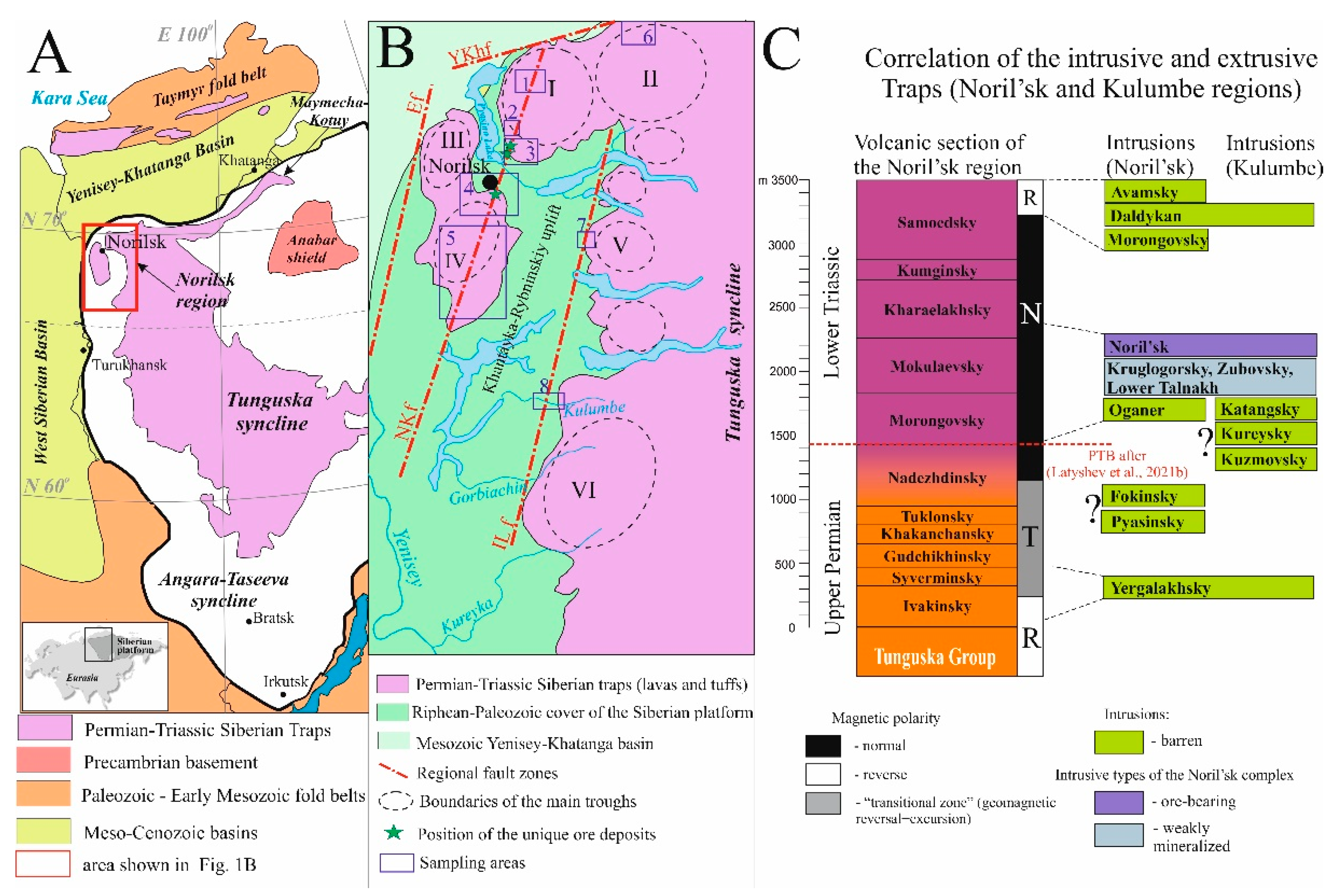
2. Geological Setting
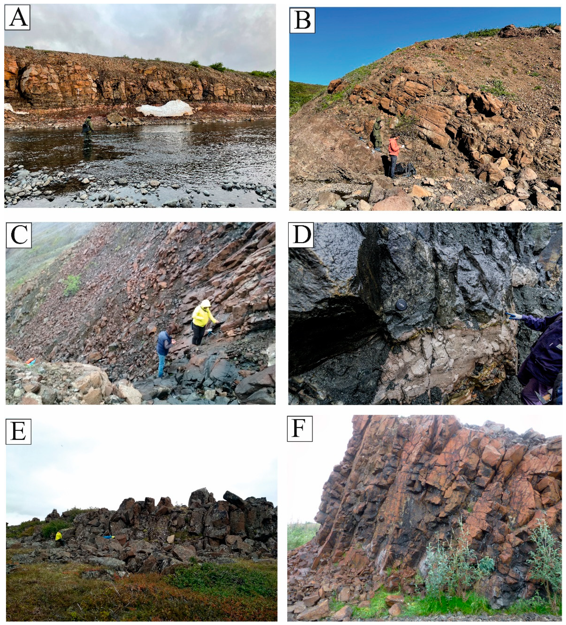
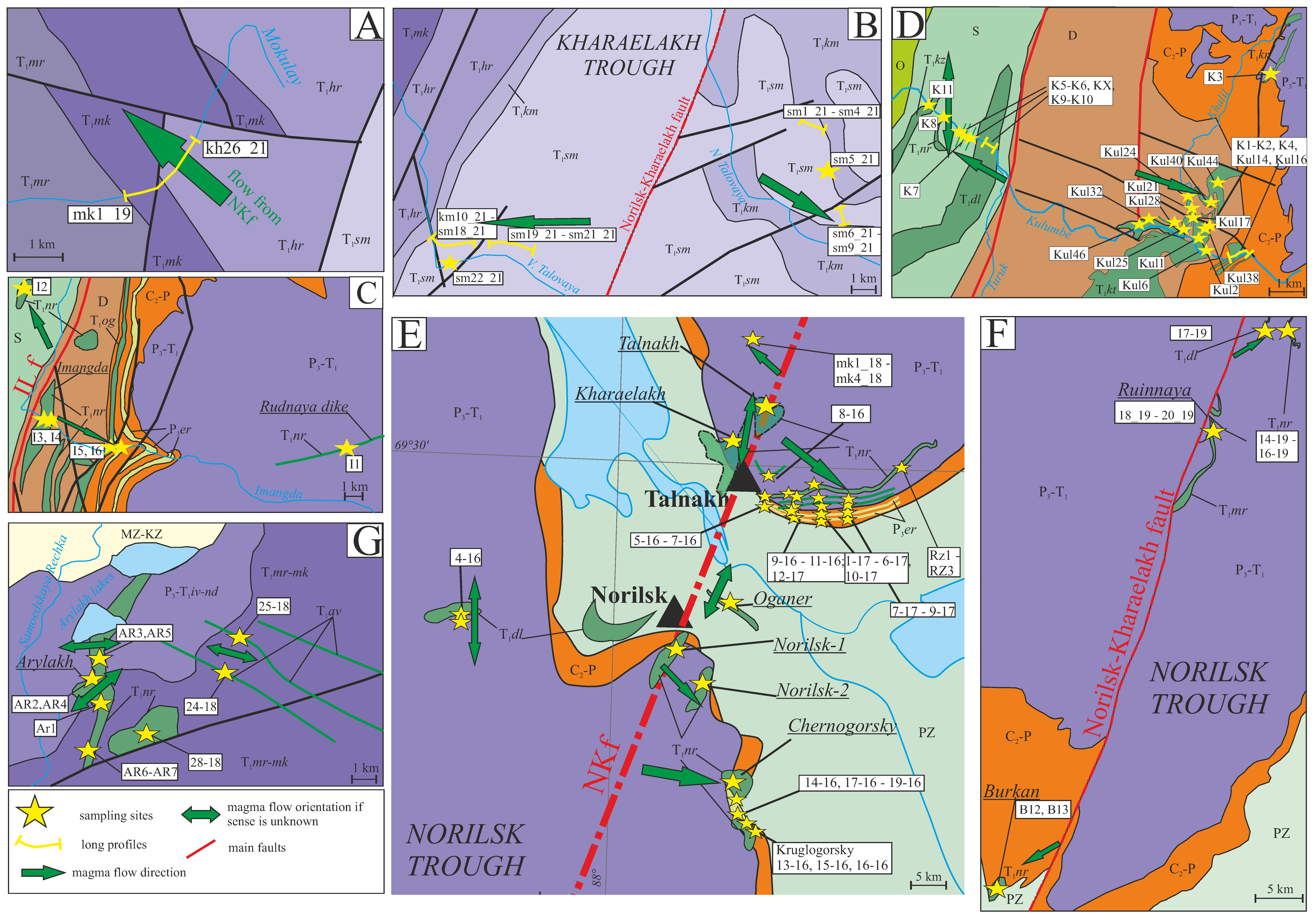
The Noril’sk region is located in the northwestern margin of the Siberian platform and occupies the key position within the LIP due to the maximal thickness of products of volcanic activity (up to 3.5 km [26]), highly diverse composition of volcanic rocks and intrusions, and presence of the unique Cu-Ni-PGE deposits, related to layered intrusive bodies. Main tectonic structures of the Noril’sk region are subcircular and elliptical depressions known as “troughs”, filled by voluminous tuff-lava piles (Noril’sk, Kharaelakh, Imangda troughs, etc.) and rampart-like uplifts (Khantayka-Rybninskiy and Pyasino swells). Main disjunctive features are regional faults of NE strike—Noril’sk-Kharaelakh, Imangda-Letninskiy, and other faults (Figure 1B). The Permian-Triassic volcanic sequence comprises eleven formations, associated with eight intrusive complexes (Figure 1C). All world-class Cu-Ni-PGE deposits are related to the only one Noril’sk intrusive type of the same complex and located near the Noril’sk-Kharaelakh fault zone.
Petrological and geochemical features of volcanic and intrusive units were reported by many authors [26,27,28,29,30,31,32]. The volcanic sequence is often subdivided into the Lower Series, mainly composed of high-Ti lavas (from Ivakinsky to Gudchikchinsky formations), the Middle (or “transitional”) Series (Khakanchansky-Nadezhdinsky formations), and the Upper Series, composed of low-Ti lavas (from Morongovsky to Samoedsky formations). It was also shown that ore-bearing intrusions of the Noril’sk type are close to the Morongovsky-Mokulaevsky formations in their geochemical features; however, their possible genetic links are still disputed. While some authors suppose that ore-bearing intrusions were formed in open magmatic systems as shallow conduits to volcanic flows [33,34,35,36,37], others suggest that intrusions were emplaced as blind bodies and do not have a direct connection with lavas [38,39,40,41].
According to a complex of geochronological, paleomagnetic, and paleontological data, it is generally accepted that formation of the main volume of Siberian Traps in the Noril’sk region took place during a short period of time (less than 1 Myr) at the Permian-Triassic boundary [23,25,42,43,44,45]. Magmatic activity was not monotonous but occurred as a series of brief intense volcanic pulses divided by more prolonged gaps [46,47].
The Kulumbe (or Kulyumber in some publications) river area is located at the junction zone of the Khantayka-Rybninskiy swell and the western slope of the Tunguska syncline. It is studied much less than the Noril’sk region, but some representative data on whole-rock chemistry for the Permian-Triassic rocks of this area have recently been published [48,49] Due to its transitional position, the Kulumbe region comprises intrusive complexes typical of the Noril’sk region (Noril’sk, Yergalakhsky, Daldykan) and the Tunguska syncline (Katangsky, Kuzmovsky). In addition, intrusions of the specific composition (the Kureysky complex) are present.
Despite the long investigation of the Noril’sk region, patterns of the magma flow during the emplacement of Traps in this area are poorly constrained. The dominant idea is that Noril’sk-Kharaelakh and Imangda-Letninskiy faults and other regional fault zones are the main magma-feeding and ore-controlling structures [50,51,52,53,54,55]. Preliminary results of AMS studies in the Noril’sk and Kulumbe regions [21,22] support this hypothesis. An alternate model suggests that magma spread along the transform fault zone transverse to Noril’sk-Kharaelakh fault [56]. Based on isopach maps for volcanic formations, some authors suppose that the center of volcanic activity migrated through time [11,32]. Within this study, we analyzed the detailed data on anisotropy of magnetic susceptibility for the intrusions and lava flows from the northwestern Siberian platform and reconstructed magma flow patterns for the Siberian Traps in these regions.

3. Sampling Areas

In total, we collected oriented samples at 195 sites, representing intrusions and lava flows from the northwestern Siberian platform. Paleomagnetic data for some of these bodies were reported before [22,23,24,25,49,57,58], and the remaining results will be published elsewhere. A brief description of sampled sites is given below.
The Talovaya area is located in the north of the Kharaelakh trough. The upper part of the volcanic sequence of Noril’sk (the Kumginsky and Samoedsky formations) is exposed here. We collected samples from 21 lava flows of the Samoedsky Formation and the uppermost flow of the Kumginsky Formation in the two most complete sections in the Verkhnyaya Talovaya (sites sm1_21–sm9_21) and Nizhnyaya Talovaya (sites km10_21, sm11_21–sm22_21) river valleys. Lava flows are flat lying (dip angles are usually less than 10°), composed of basalts, and vary from 5 to 20 m in thickness (Figure 2A).
The Mokulay section is composed of basaltic lava flows exposed along the Mokulay Creek (western slope of the Kharaelakh plateau). We sampled here 17 lava flows from the Mokulaevsky Formation (mk1_19–mk24_19) and 6 flows from the Kharaelakhsky Formation (kh25_19–kh26_26). Flows dip to the NE with angles of about 25–45° and are 5–80 m thick (Figure 2B).
The Kharaelakh area comprises ore-bearing intrusions sampled in underground mines near the town of Talnakh and sills, dikes, and lava flows in the southwestern part of the Kharaelakh trough. The ore-bearing Kharaelakh intrusion was sampled at 11 sites (16_17, 23_17–27_17, 37_17–41_17) in the Oktyabrskiy underground mine, including barren and ore-bearing gabbro-dolerites, hornfels, and massive ores. The ore-bearing Talnakh intrusion was sampled at 12 sites, representing various igneous rock types, skarns, and hornfels (sites 42_17–50_17) from the Skalisty underground mine and leucogabbro apophysis exposed near the town of Talnakh (sites 20_17–22_17). The intrusion of Zayachiy Creek (the Kruglogorsky intrusive type), which is considered to be the apophysis of the Talnakh intrusion, was sampled at nine sites in outcrops along the creeks of Ugolniy (site 27_19ZR), Zayachiy (9_16–10_16, 12.1_17–12.2_17), Taliy (10_17), and Listvyanka (RZ1–RZ3) (Figure 2C). The description of intrusions and paleomagnetic data are given in [23].
We also collected samples from thin dikes and sills of the Daldykan (four sites: 8_16, 11.2_16, 3.2_17, 4_17) and Oganer (four sites: 1_17–3.3_17) complexes. Sills of the Yergalakhsky complex cut the coal-bearing sandstones of the Tunguska group near the foot of the Kharaelakh plateau. These sills were sampled at 13 sites (5_16–7_16, 11.1_16, 11.4_16, 5_17–9_17). The descriptions of these intrusions and paleomagnetic data are given in [25].
Finally, in the Kharaelakh area, we sampled lava flows of the Ivakinsky (site 11.3_16, the Zayachiy Creek), Syverminsky (9_16sv1–9_16sv2, the Zayachiy Creek), and Mokulaevsky formations (mk1_18–mk4_18, the Olor Creek). In total, 60 sites were sampled in the Kharaelakh area.
The Noril’sk area comprises the northern part of the Noril’sk trough, the eastern part of the Vologochan trough, and slopes of the Pyasino uplift. In the Noril’sk trough, we collected samples from the ore-bearing intrusion Noril’sk-1 at 11 sites (13.1_17–19_17) in the open pit “Medvezhiy Creek” (Figure 2D). Satellites of these bodies, Noril’sk-2 and Chernogorsky intrusions with subeconomic mineralization, were sampled at five and six sites, respectively (28_17–36_17, 12_16, 20_16). In addition, the nearby Kruglogorsky intrusion (three sites: 13_16, 15_16, 16_16) and sill of the Yergalakhsky complex (four sites: 14_16, 17_16–19_16) were sampled in the same area.
In the Vologochan trough, we sampled the sill-like intrusion in the Ambarnaya river valley (site 4_16) and four host lava flows of the Morongovsky Formation (sites 4f1_16–4f6_16). Flows have thickness up to 10 m and flatly dip to the SW.
Finally, the sill of Oganer cutting the Silurian sediments was sampled in four closely located sites (1_16, 2_16, 11.1_17, 11.2_17) near the hospital of Oganer. In total, we collected samples from 38 sites in the Noril’sk area (please see [23,25] for the detailed data).
The South Noril’sk area is located in the southern part of the Noril’sk trough. Four intrusions from different parts of the Noril’sk region were studied. The intrusion of the Ruinnaya Mountain (Morongovsky complex) cuts basalts of the Mokulaevsky Formation and is up to 70 m thick. We collected samples from this intrusion at three sites (18_19–20_19), representing layered and tholeiitic gabbro-dolerites. A possible coeval sheet intrusion of the Daldykan complex was sampled northward of the Ruinnaya Mountain (site 17_19). The sill-like sheet of the Kruglogorsky type (about 50 m thick) is located within basaltic flows of the Nadezhdinsky Formation and possibly represents the apophysis of the South Noril’sk intrusion. We sampled this intrusion at three closely located sites (14_19–16_19). Finally, we collected samples at two sites (B12, B13) from leucogabbro and gabbro-dolerites of the Burkan Mountain intrusion (the Noril’sk type). This intrusion is located within the Paleozoic sediments and is about 40 m thick in the sampling area.
The Icon area is located 150 km NE of Noril’sk, within the Icon trough. The Arylakh layered intrusion (Figure 2E) with weak mineralization (the Noril’sk type) was sampled at seven sites (AR1–AR7). This intrusion has complicated morphology, cuts basalts of Tuklonsky, Nadezhdinsky, and Morongovsky formations, and exceeds 40 m in thickness. We also collected samples from the nearby barren intrusion of the Noril’sk type (site 28_18) and two dikes of the Avamsky complex (sites 24_18 and 25_18).
The Imangda area comprises the western flank of the Imangda trough. We collected samples from the Imangda weakly mineralized intrusion (I3, I4) and Khyukta sill (I2), which are attributed to the Noril’sk type. Two sills referred to the Oganer (I5), and Yergalakhsky (I6) complexes were sampled as well (Figure 2F). All these intrusions conformably lay within the Paleozoic sediments, flatly dip to the east, and are from 15 to 40 m in thickness. In addition, basalts of the Tuklonsky Formation near the contact of the Rudnaya dike were sampled at site I1.
In the Kulumbe region, Permian-Triassic intrusions are exposed in the western slope of the Nirungda trough and conformably lay among the Paleozoic sedimentary rocks, flatly dipping to the east. Rarely, intrusions cut the lowermost flows of the Syverminsky Formation. Intrusions are composed of dolerites and gabbro-dolerites and are from 5–6 to 60 m in thickness. The tectonic structure of the region is complicated by the regional Imangda-Letninskiy fault zone, which extends northeast and limits the Khantayka-Rybninskiy uplift. We collected samples from 27 intrusions, representing the Katangsky (13 sites), Kureysky (5 sites), Daldykan (5 sites), Yergalakhsky (site K4), and Kuzmovsky (site K11) complexes and Kruglogorsky (site K8–Iltyk intrusion) and Noril’sk (site K7—Siluriyskaya intrusion) types.

4. Materials and Methods

The oriented samples were collected as drill cores or as hand blocks. The orientation of samples was performed using the magnetic and, when possible, sun compasses in natural outcrops and open pits. In the underground mines, we used mine surveying marks and a homemade system based on a laser theodolite and inclinometer for the precise orientation of samples. The local magnetic declination was calculated using the IGRF model (13th generation).
The rock-magnetic procedures were carried out using the equipment of the Shared Research Facilities Center “Petrophysics, geomechanics and paleomagnetism” Schmidt Institute of Physics of the Earth (IPE RAS, Moscow, Russia) [59]. Anisotropy of magnetic susceptibility (AMS) was measured by the kappa-bridge MFK-1FA using Safyr 7 software (AGICO, Brno, Czech Republic). The processing of the results was performed with Anisoft42 software using Jelinek statistics [60]. To analyze the AMS ellipsoid, Pj (corrected degree of anisotropy) and T (ellipsoid shape) parameters were used [61].
Thermomagnetic Ms(T) curves were measured using a vibrating magnetometer constructed by Yu.K. Vinogradov (the Borok Geophysical Observatory, Yaroslavl region, Russia) with an applied magnetic field of 0.5 T. Thermal dependence of the magnetic susceptibility was measured using a CS-3 heating add-on to the MFK-1FA kappa-bridge. The hysteresis loops, back-field demagnetization curves of saturation IRM, and first order reversal curves were recorded using the vibrating sample magnetometer PMC MicroMag 3900 (Lake Shore Cryotronics, USA) at room temperature in a 0.5 T saturating field. The domain structure of ferromagnetic grains was determined according to the Day–Dunlop plot [62,63] and FORC diagrams [64].
Anisotropy of anhysteretic remanent magnetization (AARM) measurements were carried out using an AF demagnetizer LDA5 and spinner magnetometer JR6 (AGICO). The samples were gradually demagnetized on LDA5 at AC max amplitude of 200 mT with linear decrease, then samples were magnetized at AC of 100 mT and DC max amplitude of 500 mT in C-mode (6 directions). After magnetization in each direction in the C-mode, the anisotropy was recorded on a spinner magnetometer JR6. The processing of results was performed with Anisoft42 software.

5. Results

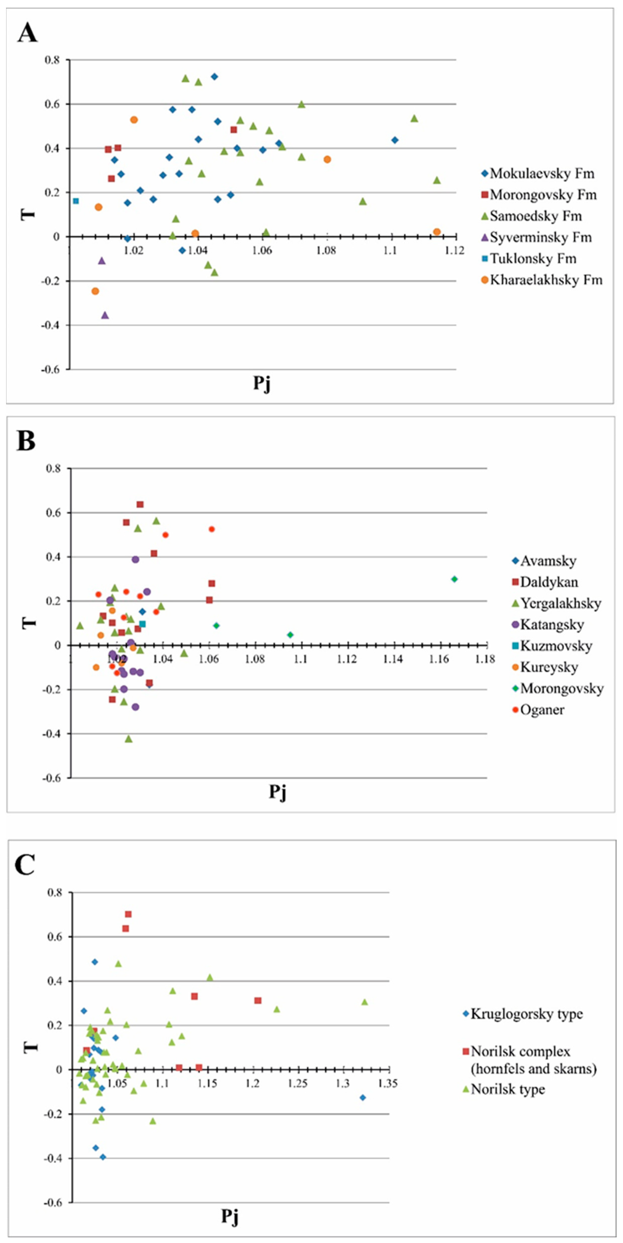
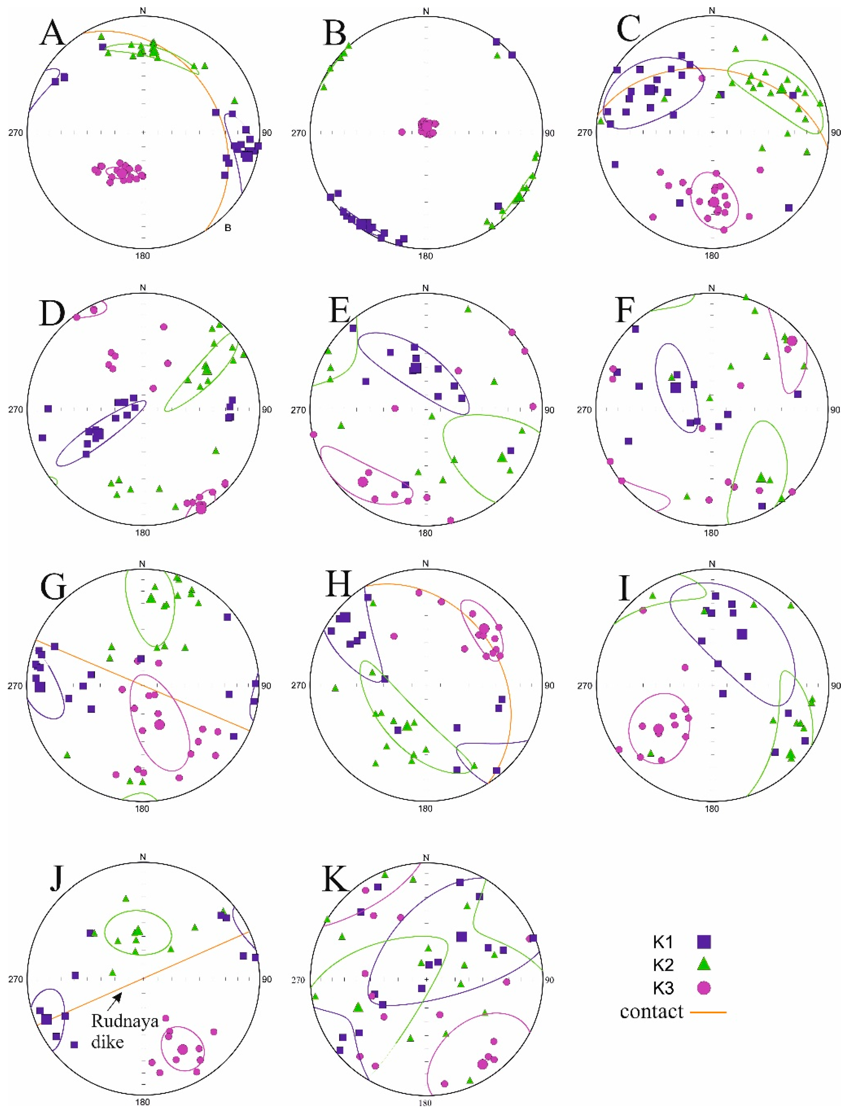
5.1. Anisotropy of Magnetic Susceptibility

The majority of studied rocks have a low degree of anisotropy of magnetic susceptibility Pj. In about 80% of sites, Pj is less than 1.06 (Supplementary Material Table S1; Figure 3). Only 7% (12 sites) demonstrate Pj > 1.1. Low values of the Pj parameter are typical of mafic rocks with a magnetic fabric of primary magmatic origin where magnetite or titanomagnetite are the main magnetic minerals [65]. Absence of the strong metamorphic alteration and signs of deformations in most of the rocks confirm the magmatic genesis of the magnetic fabric. The highest degree of anisotropy (Pj > 1.1) is demonstrated mainly by sulfide-bearing rocks of the Noril’sk and Talnakh intrusions, massive sulfide ores, and hornfels with superimposed magnetic fabric, affected by the emplacement of nearby intrusions.
Values of the T parameter characterizing the shape of the AMS ellipsoid [61] vary from −0.4 to 0.5 for most sites. About 70% of sites demonstrate the oblate AMS ellipsoid (T > 0); herewith, the most oblate ellipsoid (T > 0) is typical of the Mokulaevsky and Samoedsky lava flows (Figure 3A,B). The prolate form of the AMS ellipsoid (T < 0) in mafic rocks is often interpreted as a result of the magma flow, while the oblate ellipsoid is considered to result from static processes such as compression during cooling, crystallization in situ, or gravitational differentiation [66,67]. As seen from Figure 3C, most of the sites with the highest degree of anisotropy demonstrate the oblate form of the ellipsoid. Thus, we suggest that sulfide mineralization leads to the highly anisotropic oblate ellipsoid of AMS.
The normal type of magnetic fabric (N-type), when the minimal axis of the AMS ellipsoid (K3) is orthogonal to the contact of lava flow or intrusion and two other axes lie in the plane of the magmatic body, was identified for 102 sites (~52%). The major part of lava flows from the Talovaya and Mokulay sections, and many sill-like intrusions from different regions, demonstrate this type of magnetic fabric (Figure 4A–C). In these sites, the K3 axis is subvertical or steep, while the two other axes have a flat orientation and lie in the plane of the sill or lava flow. In some sites, magnetic lineation (the maximal K1 axis of the AMS ellipsoid) is tightly grouped; in others, it forms a great-circle arc with the directions of the intermediate K2 axis. Imbrication of the K1 axis from the contact plane is commonly negligible, but, for some sites, it reaches 20–25°, which could have been caused by a turbulent magma flow.
In 33 sites (17%), we identified the inverse, or reverse, type of the magnetic fabric (R-type). In those sites, the K1 axis is orthogonal to the contact plane and the two other axes lie in the flow or intrusion plane. This behavior of the AMS ellipsoid was found in flat intrusions of the Yergalakhsky and Katangsky complexes and Noril’sk type, as well as in some other sites (Figure 4D–F). The possible reasons for the magnetic fabric inversion are discussed below.
An intermediate type of the magnetic fabric (I-type), when the medium axis K2 is normal to the contact, was identified in 17 sites (9%). This behavior of the AMS ellipsoid occasionally occurs in sills, dikes, and lava flows from different regions (Figure 4 G,H). In the remaining 42 sites (22%), axes of the AMS ellipsoid are either scattered (S-type) or diagonal (D-type) to the contact (Figure 4I–K). Generally, this fabric is typical of the sulfide-bearing rocks or sites with the lowest degree of anisotropy (Pj < 1.01). Sites with scattered or diagonal magnetic fabrics are not used in the further interpretation below.
Thus, studied intrusions and lava flows demonstrate variable and sometimes complicated magnetic fabric. To reconstruct the directions of magma transport, we selected the most relevant sites using the following criteria:
  • We used an F-test [68] inbuilt in the program “Safyr 7” to exclude the unreliable measurements. This test shows whether differences between measured principal susceptibilities are great enough compared with measurement errors. Usually, the critical value of the F parameter is estimated as ~3.4–4 [69,70]. We used a more conservative approach and excluded specimens with F < ~100 from further calculations. This approach led to a reduction of the within-site scatter for some intrusions.
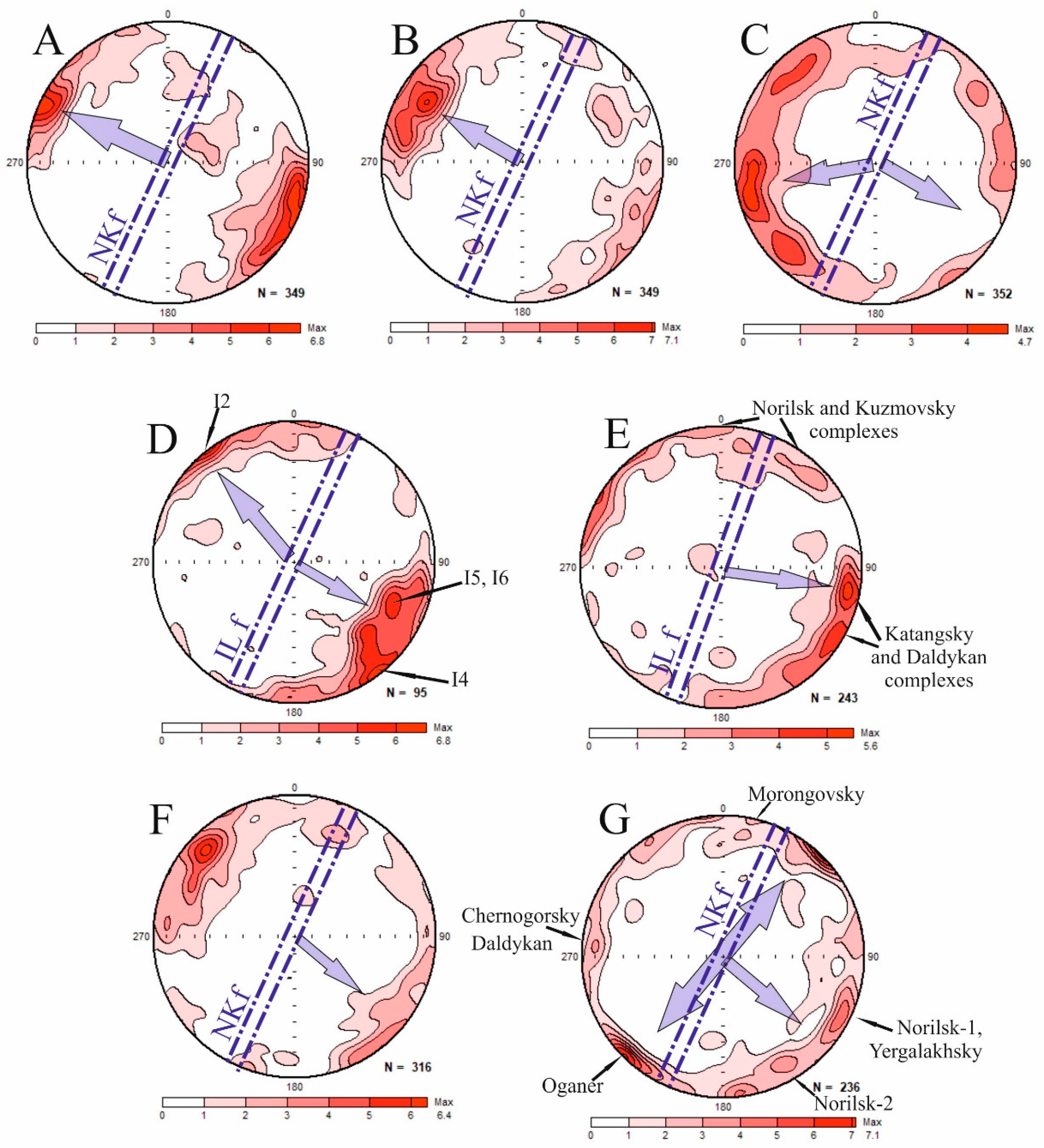
  • Only sites with N-type magnetic fabric were analyzed. For those sites, the magnetic lineation (maximal axis K1 of the AMS ellipsoid) was interpreted as the magma flow orientation, following [14,15,71] and many others. An alternate method suggested in [72] is to use an imbrication of magnetic foliation with respect to contacts of the magmatic body. However, due to sampling conditions and the complex morphology of many intrusions, it was not possible to apply this method.
  • Samples with the essential amount of sulfides (pyrrhotite, pyrite, etc.) and a high degree of anisotropy were excluded from the analysis. Thus, the significant majority of sites representing ore-bearing intrusions and their contact zones was not used for the reconstruction.

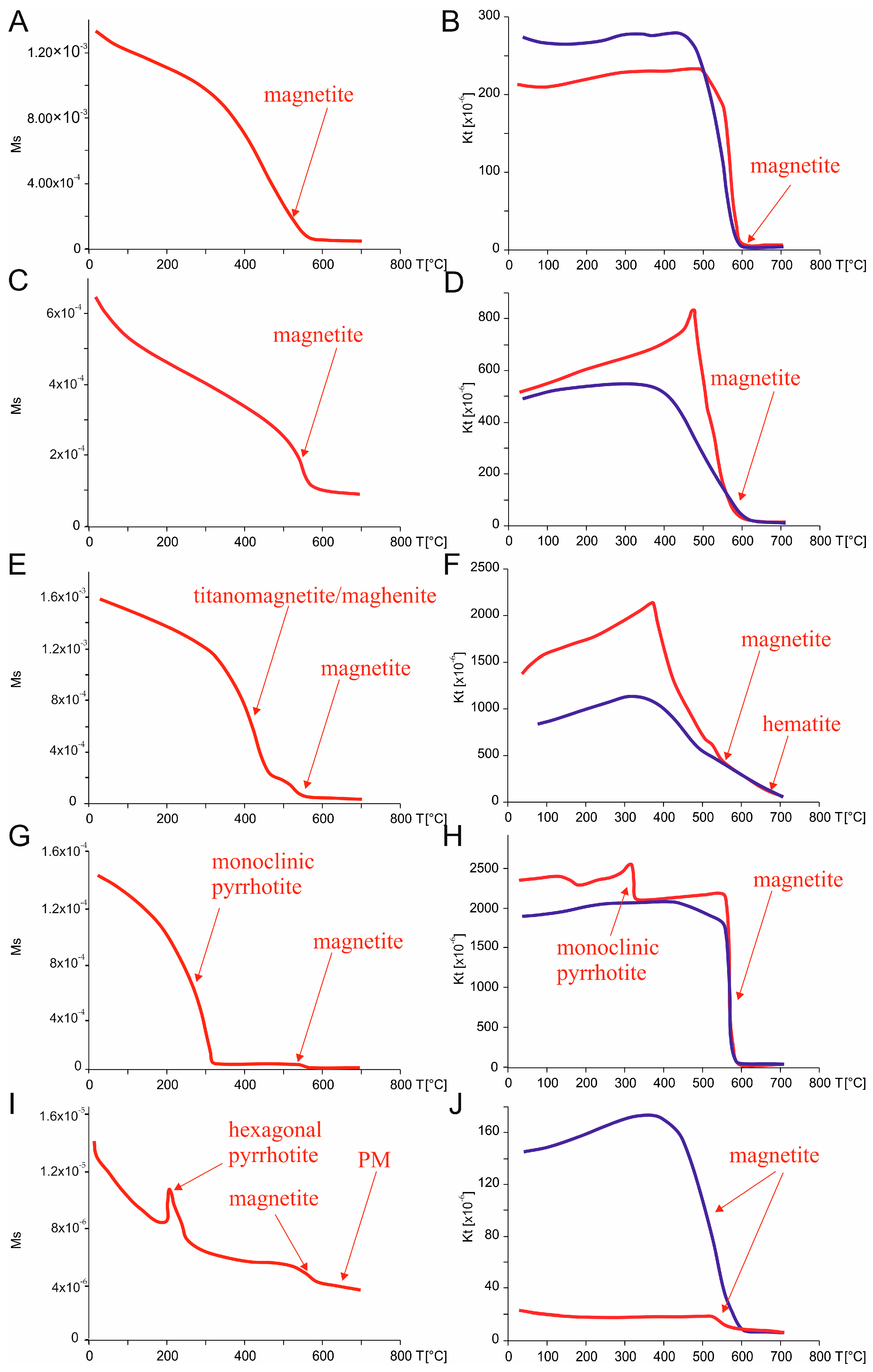
5.2. Rock-Magnetic Properties

We performed a detailed rock-magnetic investigation to determine the composition of magnetic minerals and their domain structure in the studied rocks. Based on rock-magnetic features, all samples from different intrusions can be divided into three groups. The full description of magnetic properties is presented in [23,24,25]; a brief summary is given below.
In the first group, magnetite or low-titanium titanomagnetite are the main magnetic minerals. Temperature dependencies of the saturation magnetization (Ms(T)) and the magnetic susceptibility (K(T)) demonstrate the predominance of the single magnetic phase with Curie temperatures of about 570–590 °C or 500–540 °C (Figure 5A–D). Occasionally, a small amount of hematite is identified at K(T) curves by the decrease of magnetic susceptibility near temperatures of about 670 °C. In a few samples, two magnetic phases are identified: magnetite and titanomagnetite or maghemite (Figure 5E). Many samples of this group are stable to heating, but, sometimes, magnetic susceptibility decreases after cooling, probably due to the decay or oxidation of magnetite or to the presence of some amount of maghemite (Figure 5F). These rock-magnetic properties are typical of the Siberian Traps and were reported before, both for lavas [43] and intrusions [23,73,74]. The majority of samples from lava flows and barren or weakly mineralized intrusions belong to this type.
The main feature of the second group is the presence of iron sulfides, which are identified by the thermomagnetic curves. Pyrrhotite occurs both as monoclinic and hexagonal forms. The former is demonstrated at Curie temperatures of about 300 °C to 350 °C (Figure 5G,H); the latter is identified by λ-peak [75] at temperatures of about 180 °C to 250 °C in the thermomagnetic curves (Figure 5I). In addition, pyrite is identified by the growth of magnetic susceptibility above 400 °C due to magnetite formation. After heating up to 700 °C, iron sulfides are strongly oxidized, causing the increase in all magnetic parameters in cooling curves. Besides sulfides, some amount of magnetite is occasionally present in the samples of this group. Sulfide-bearing samples usually demonstrate high degrees of anisotropy and widely scattered distributions of AMS axes. Many sites from ore-bearing intrusions and their contact zones represent this group.
The third group comprises weakly magnetic samples from different bodies. The Ms(T) thermomagnetic curves demonstrate a concave shape, indicating the predominance of paramagnetic material (Figure 5I). The temperature dependencies of magnetic susceptibility allow us to observe a small amount of magnetite, hematite, pyrrhotite, or pyrite. After heating up to 700 °C, the amount of magnetite and, consequently, Ms and K values increase on cooling (Figure 5J). This type is occasionally identified in different rock types, mainly leucogabbro and hornfels from contact zones of ore-bearing intrusions.
Although values of hysteresis parameters vary in wide ranges for different intrusions and lava flows, in the Day–Dunlop plot, most of samples are located in the pseudo-single domain area and concentrated along the mixing curve of single-domain and multidomain grains [63]. This behavior of hysteresis parameters is typical of the Siberian Traps intrusions [23,25]. As seen from Figure 6A, samples with different types of magnetic fabric do not reveal any differences in hysteresis parameters. For the detailed analysis of the domain structure, first order reversal curves (FORC) were recorded for the selected specimens. According to FORC diagrams, in samples from lavas and intrusions, attributed to N-type of magnetic fabric, multidomain grains of low-coercive minerals (magnetite or low-titanium titanomagnetite) interacting with each other dominate the magnetic structure (Figure 6B,C). Gabbro-dolerites of the Ruinnaya intrusion (the Morongovsky complex, R-type AMS) demonstrate the presence of interacting particles of various domain structures, mainly of low-coercive mineral (Figure 6D). Basalts from the Samoedsky Formation (R-type AMS) show the predominance of single-domain or pseudo-single-domain grains of magnetite or titanomagnetite and presence of a small amount of interacting particles of very low-coercive mineral (possibly maghemite) (Figure 6E). Finally, in sulfide-rich rocks from the contact zone of the Kharaelakh intrusion, strongly interacting multidomain grains of very low-coercive magnetic phase (pyrrhotite) are predominant (Figure 6F).

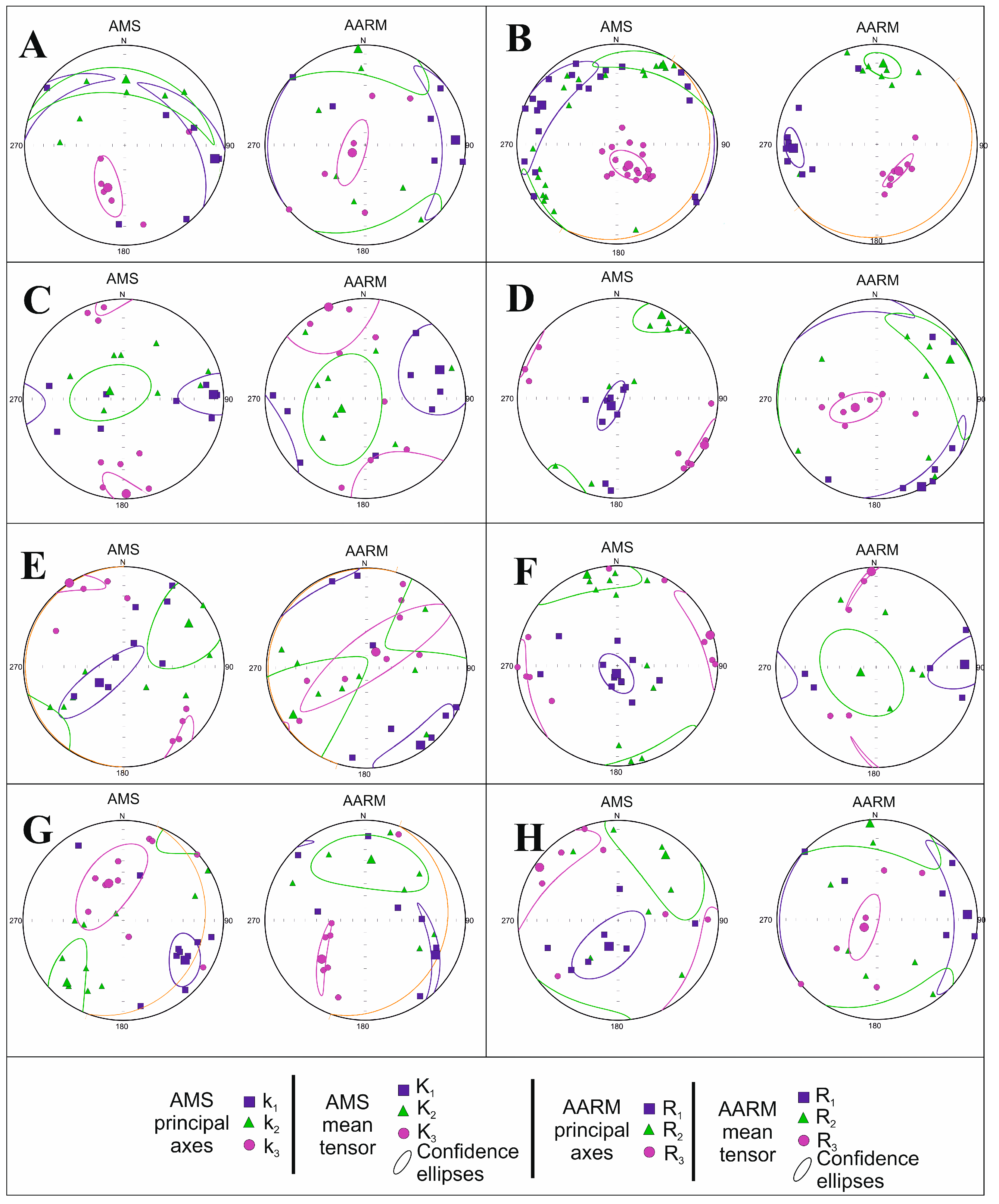
5.3. Anisotropy of Anhysteretic Remanent Magnetization

To isolate the contribution of ferromagnetic minerals from that of the para- and diamagnetic matrix, we measured anisotropy of anhystereric remanent magnetization (AARM) for the selected sites with various types of magnetic fabric (Table 1). Site-mean corrected degree of AARM Pj varies from 1.1 to 1.6 and is somewhat higher than that of AMS (1.03–1.12 in the same sites), possibly due to elimination of the influence of the matrix [76]. The shape of the AARM ellipsoid differs from that for AMS and is prolate in 50% of sites (T > 0). Thus, predominance of oblate AMS fabric can partially be caused by paramagnetic minerals.
Gabbro of the Kharaelakh intrusion (site 24_17) and basalts of the Samoedsky Formation (site sm12_21) demonstrate coaxial AARM and AMS fabric. For both sites, minimal site-mean axes of AARM and AMS are steep or subvertical, and other axes are flat, corresponding to the N-type of anisotropy in layered intrusions and lava flows (Figure 7A,B). Thus, magnetic fabric in these sites is dominated by remanence-bearing minerals, mostly magnetite.
Near-contact gabbro-dolerites of the Talnakh intrusion (site 48_17) also show similar orientations of AMS and AARM axes. Both ellipsoids demonstrate subvertical magnetic foliation of W-E strike and horizontal magnetic lineation (Figure 7C). Since samples were collected near the bottom of the intrusion, we suggest that observed magnetic fabric reflects the local orientation of the contact surface.
Samples from the sill of the Yergalakhsky complex (site 5_16) and basaltic flow of the Samoedsky Formation (site sm1_21) demonstrate the inversion of magnetic fabric: R-type of AMS changes to N-type of AARM (Figure 7D,E). This phenomenon is well known and usually explained as a result of single-domain magnetite behavior [77]. Supporting this, samples from site 5_16 are close to the single-domain field in the Day–Dunlop plot (Figure 6A). Furthermore, the FORC diagram for a sample from site sm1_21 points out the presence of single-domain magnetite (Figure 6E). Thus, origin of the inverse magnetic fabric in the studied intrusions and lava flows can partly be explained by features of the domain composition. However, the majority of samples with R-type of AMS are rather far from the single-domain area in the Day–Dunlop plot (Figure 6A), hence, this hypothesis cannot be applied to all sites with inverse fabric.
The dike of the Daldykan complex (site 11.2_16) demonstrates another type of inversion of magnetic fabric. Unlike previous site, AMS fabric belongs to I-type with subvertical magnetic foliation, normal to dike walls. AARM measurement shows the N-type with horizontal magnetic lineation (Figure 7F). According to [78] or [79], this kind of magnetic fabric can result from superposition of two different fabrics. These fabrics can be formed by two generations of magnetite or ferromagnetic and paramagnetic minerals.
In site kul32 (sill of the Katangsky complex), medium and minimal axes of the AARM ellipsoid form a girdle and change over compared with AMS fabric (Figure 7G). However, the maximal axis is similar for AARM and AMS ellipsoids and lies in the plane of intrusion. Since the magnetic lineation has the same orientation both in AARM and AMS fabrics, we suggest that it can be used for the magma flow reconstruction.
For site 26_17 (taxitic gabbro-dolerites of the Kharaelakh intrusion), the orientation of the AARM axes does not correspond to that of AMS and is oblique to the presumably horizontal contact of massif (Figure 7H). We suggest that monoclinic pyrrhotite, identified in magnetic susceptibility thermal curves (Figure 5H), is responsible for the imbrication of the AARM ellipsoid.
Thus, measurement of AARM showed that, for sites with N-type, magnetic fabric is controlled by ferromagnetic minerals (mainly magnetite or titanomagnetite of pseudo-single-domain or multidomain composition) and can be used for the reconstruction of magma transport patterns. An inverse magnetic fabric, in some cases, can be explained by the significant contribution of single-domain grains of magnetite or titanomagnetite. Finally, presence of iron sulfides disturbs and obscures the primary magmatic magnetic fabric and complicates the interpretation of AMS and AARM measurements.

6. Discussion

In the Mokulay section, the majority of sampled lava flows of the Mokulaevsky and Kharaelakhsky formations demonstrate normal magnetic fabric (20 from 23). For most of them, the magnetic lineation is gentle and has NW–SE strike in the geographic coordinate system (Figure 8A). Given that the entire lava sequence dips to the NE, the sense of lava motion cannot be determined. After the tilt correction, the mean value of the K1 axis for all sites gently dips to the NW (Figure 8B). Therefore, we suggest that lava flows moved from SE to NW. It should be noted that, in sites MK1_19 and MK10_19, which show intermediate magnetic fabric, magnetic lineation is close to the main group (Supplementary Material Table S1) and, possibly, reflects the motion of flows as well.
The mean magnetic lineation calculated for the Mokulay section is virtually orthogonal to the Noril’sk-Kharaelakh fault (Figure 8A), which is located eastward of the sampling area (Figure 9A). Hence, results from the Mokulay section show that the Mokulaevsky and Kharaelakhsky lava flows moved from the Noril’sk-Kharaelakh fault, where the eruptive center was located. This interpretation is consistent with previous results reported by Callot et al. [21] for the upper part of the Noril’sk volcanic section from the Icon trough.
In the Talovaya area, the majority of lava flows demonstrate N-type magnetic fabric as well (18 flows from 22). Since flows are flat lying (dip < 10°), we analyzed the orientation of the maximal AMS axis in the geographic coordinate system. In the contour plot for the K1 axis, several local centers can be distinguished (Figure 8C). They correspond to distinct groups of lava flows with different directions of motion. Mean values of major clusters gently dip to the NW or SW. The group with northwestern dip of the magnetic lineation is close to the main cluster for the Mokulay section and nearly orthogonal to the Noril’sk-Kharaelakh fault (Figure 9B). We also note that site sm1_21 (R-type of AMS) demonstrates normal fabric of AARM with a similar NW orientation of the maximal axis and can be attributed to the same group. Thus, eruptions of the Samoedsky lava flows were controlled by the Noril’sk-Kharaelakh fault as well, though several local stages with different eruptive centers can be distinguished.
Intrusions of the Imangda area demonstrate normal magnetic fabric with a predominant SE dip of the magnetic lineation (Figure 8D). Within the main cluster, two local centers are distinguished, corresponding to two different stages of emplacement. Sites I2 and I4 represent the Khyukta and Imangda intrusions, respectively, both referred to as the Noril’sk type. Sites I5 and I6 represent the Oganer and Yergalakhsky complex, respectively, and possibly mark the earlier magmatic events. In general, magnetic lineation in all these sites is orthogonal to the Imangda-Letninskiy fault (Figure 9C), pointing out the transport of magma from this magma-feeding fault zone. The only exception is site I3 (the Imangda intrusion), where the K1 axis of AMS is horizontal and has meridional strike (Supplementary material Table S1). This kind of magnetic fabric can be caused by magma flow along the Imangda-Letninskiy fault, which is located nearby. Finally, basalts of the Tuklonsky Formation (site I1) demonstrate magnetic foliation parallel to the wall of the proximate Rudnaya dike. We suggest that the primary fabric of this site was overprinted during the dike emplacement and mineral alterations near the contact.
In the Kulumbe region, 15 sites out of 27 showed normal magnetic fabric. As seen from Figure 8E, in most sites, magnetic lineation gently plunges to the E–SE. This cluster is formed mainly by intrusions of the Katangsky and Daldykan complexes. The dip of magnetic lineation for this group is virtually orthogonal to the Imangda-Letninskiy fault, indicating the direction of emplacement of intrusions and magma-controlling role of this fault (Figure 9D). However, Siluriyskaya (site K7) and Iltyk (K8) intrusions (the Noril’sk complex) and the Kuzmovsky sill (K11) demonstrate flat meridional orientation of K1 axes, close to the strike of the Imangda-Letninskiy fault zone. These intrusions may correspond to a distinct magmatic event.
The Kharaelakh area is more complicated for the interpretation of AMS data. Only 21 sites out of 70 yielded normal magnetic fabric. Partly, those were hornfels and skarns from the contact zones of ore-bearing intrusions, which are not applicable for the magma flow reconstruction. Among the rest, most sites demonstrate NW-dipping magnetic lineation (Figure 8F). The main center of mass in the contour plot is formed by the intrusion of Zayachiy Creek (three sites), the Kharaelakh intrusion (three sites), the Mokulaevsky Formation (four lava flows), and a single lava flow from the Ivakinsky Formation. For this group, magnetic lineation is oriented across the Noril’sk-Kharaelakh fault zone and is consistent with the idea of the lateral magma transport from the magma-conducting fault in both sides (Figure 9E). Other sites, representing sills and dikes of the Yergalakhsky and Daldykan complexes and parts of the Kharaelakh intrusion, demonstrate variable orientations of the K1 axis of AMS, different from the main group.
AARM fabric, measured for the Yergalakhsky sill 5_16 (R-type of AMS), demonstrates the normal type, where the maximal axis is flat and close to the main cluster of the Kharaelakh area (Figure 7D). For the Daldykan dike 11.2_16 (I-type of AMS), the maximal axis of AARM is horizontal, pointing out the lateral magma flow (Figure 7E). In both sites, AARM fabric supports our interpretation of the dominant magma transport from the Noril’sk-Kharaelakh fault to the NW and SE.
For the Talnakh intrusion, we were not able to reconstruct the directions of magma emplacement because the inverse magnetic fabric is predominant (Supplementary Material Table S1). Taken together with various directions of K1 obtained for the Kharaelakh intrusion, these results show that thick, ore-bearing intrusions are challenging for the analysis of magnetic fabric. Possible reasons for that are the complex internal structure of layered multiphase intrusions and presence of iron sulfides. In addition, many sites representing dikes of Oganer and the Daldykan complex, sills of the Yergalakhsky complex, and leucogabbro of the Kruglogorsky-type intrusions have abnormal types of magnetic fabric, and reconstruction of magma flow was not performed for them.
In the Noril’sk area, only 18 sites out of 38 showed the normal type of AMS. As seen from Figure 8G, several mass centers and corresponding directions of magma flow can be distinguished in the contour plot of the magnetic lineation. For the sill of Oganer, four sampled sites demonstrate SW-NE subhorizontal magnetic lineation. Furthermore, NW-SE lineation, orthogonal to the Noril’sk-Kharaelakh fault and typical of other studied areas, has been identified in two sites of Noril’sk-1 intrusion and sills of the Yergalakhsky complex and in a single site of Noril’sk-2 intrusion. The Ambarnaya intrusion (site 4_16, Daldykan complex) and two sites of the Chernogorsky intrusion (Noril’sk type) demonstrate flat N-E magnetic lineation. Finally, for two lava flows of the Morongovsky Formation, the maximal axes of AMS gently dip to the north. Other sites from all ore-bearing layered intrusions (Noril’sk-1, Noril’sk-2, Chernogorsky) demonstrate abnormal magnetic fabric (mainly R-type) or, in a few sites, normal fabric with outlying magnetic lineation.
In the South Noril’sk area, we identified the N-type of AMS only for two sites: B12 (gabbro-dolerites of the Burkan intrusion, Noril’sk type) and 17_19 (dolerites of the Daldykan complex). Both of them demonstrate flat SW dips of magnetic lineation (Figure 9F), unlike other regions. Sampled intrusions of the Morongovsky complex and Kruglogorsky type demonstrate variable magnetic fabric, probably due to the complex morphology of bodies and rock composition.
Finally, in the Icon area, most sampled sites represent the Arylakh intrusion. Magnetic fabric varies from site to site; in general, all mean AMS axes demonstrate wide confidence ellipses. Two sites with N-type fabric (AR2 and AR5) show different orientations of the maximal K1 axis. Such magnetic fabric can be interpreted as a result of the slow cooling of the intrusion within the stationary magmatic chamber. The low degree of anisotropy in all sites (Pj < 1.025) favors this hypothesis. One out of two Avamsky dikes (site 24_18) demonstrates the I-type of magnetic fabric with a steep orientation of the minimal axis of AMS and a subhorizontal maximal axis. This type of fabric in mafic dikes was reported by Park et al. [80] and is interpreted as a result of vertical compaction of the static magma column during the cooling of magma after the lateral emplacement in a tectonic setting of subhorizontal extension. In this case, the orientation of K1 axes corresponds to the magma flow, and, hence, this dike was emplaced during the lateral transport of magma (Figure 9G).
Thus, in six studied areas, we distinguished predominant directions of magma transport from the Noril’sk-Kharaelakh and Imangda-Letninskiy fault zones. For the Mokulaevsky, Kharaelakhsky, and Samoedsky formations, we suggest the motion of lava flows to the NW and SE from the Noril’sk-Kharaelakh fault during the fissure eruptions. For the major parts of intrusions in the Noril’sk, Kharaelakh, and Imangda troughs and the Kulumbe area, the reconstructed pattern of magma transport supports the idea of the magma-controlling and magma-feeding role of regional fault zones of NE strike. This is important for the understanding of Cu-Ni-PGE ore genesis because in all studied regions, layered intrusions with mineral deposits are located at fault zones: Talnakh and Kharaelakh intrusions in the Kharaelakh trough, Noril’sk-1 and its satellites in the Noril’sk trough, the Imangda intrusion in the same-titled trough, and the Siluriyskaya intrusion in the Kulumbe area.
Minor directions of the magma transport correspond to the emplacement of individual intrusions during distinct magmatic events, e.g., formation of the Oganer sill. In addition, in some regions, the lateral transport along the fault zones was identified based on the NE orientation of magnetic lineation.
The patterns of magma transport in the Noril’sk and Kulumbe regions differ sharply from that in the Angara-Taseeva depression [20], where lateral transport of magma via the system of sills led to the emplacement of thick and extended intrusions (the Tolstomysovsky, Padunsky sills, etc.). The possible reason is the different crust structure and tectonic evolution of these regions. The Noril’sk and Kulumbe regions are superimposed to the Noril’sk-Igarka paleorift zone, identified on the basis of geophysical data [81]. The Noril’sk-Kharaelakh and Imangda-Letninskiy faults extend along this structure and represent long-lived mobile zones of high permeability. All economically important Cu-Ni-PGE deposits in the northwestern Siberian platform are located within these zones and are linked with the magma conduits. Proximity of the Noril’sk and Kulumbe regions to the supposed center of the Siberian plume can lead to the activation of fault zones, ascent of large volumes of magma, and fissure eruptions. In contrast, the Angara-Taseeva depression is a Paleozoic sedimentary basin within the Siberian platform, and the magma-feeding zone was located in the central, most subsided part of the syncline. The reconstructed magma transport pattern for the Angara-Taseeva depression was typical for such basins [17,82]. The peripheral position of the Angara-Taseeva depression and absence of regional extension zones led to the reduced thickness of the volcanic sequence compared with the Noril’sk region.

7. Conclusions

  • Based on the detailed AMS measurements, we reconstructed the magma transport patterns for the Siberian Traps in the Noril’sk and Kulumbe regions (northwestern Siberian platform). The lateral flow of NW-SE directions is predominant in most areas, supporting the model of a magma-feeding and ore-controlling role of the Noril’sk-Kharaelakh and Imangda-Letninskiy faults, as well as fissure type of lava eruptions.
  • Minor directions of SW-NE strike are identified in several areas, indicating the transport of magma along regional faults.
  • Lava flows and thin sills usually demonstrate N-type of magnetic fabric and are suitable for the determination of magma flow. Layered ore-bearing intrusions often show complicated magnetic fabric due to the complex morphology and presence of iron sulfides.
  • The detailed measurements of AARM and rock-magnetic investigation show that abnormal magnetic fabric in some intrusions and lava flows can be explained by features of domain composition of magnetite or titanomagnetite.
  • Patterns of magma transport for the Noril’sk-Kulumbe region and Angara-Taseeva depression are contrasting due to the different tectonic structure of the crust.

Supplementary Materials

The following supporting information can be downloaded at: https://www.mdpi.com/article/10.3390/min13030446/s1, Table S1: Results of anisotropy of magnetic susceptibility measurements. AMS types: N—normal, R—reverse, I—intermediate, S—scattered, D—diagonal. Pj—corrected degree of anisotropy, T—shape parameter; K1, K2, K3—maximal, medium and minimum axes of AMS ellipsoid, respec-tively; D—declination, I—inclination.

Author Contributions

Conceptualization, A.L.; methodology, A.L.; field work and sampling, A.L., V.R., R.V., N.K., A.F. and S.F.; measurements, A.L., R.V., A.F. and S.F.; data processing, A.L.; resources, V.R.; interpretation, A.L.; writing—original draft preparation, A.L.; writing—review and editing, R.V., A.F. and S.F.; visualization, A.L., R.V., A.F. and S.F.; funding acquisition, A.L., V.R. and N.K. All authors have read and agreed to the published version of the manuscript.

Funding

This study was funded by Limited Liability Company “Noril’skgeologiya” (projects No. NG-172/17, NG-130/18, NG-140/19), by the Russian Foundation for Basic Research (projects 18-35-20058, 17-05-01121, 18-05-70094 and 20-05-00573) and by state assignment of IPE RAS.

Institutional Review Board Statement

Not applicable.

Informed Consent Statement

Not applicable.

Data Availability Statement

Data are available on request.

Acknowledgments

Authors gratefully thank A.A. Lapkovsky and A.A. Ketrov (Noril’skgeologiya) for the help during field work and V.E. Pavlov, A.M. Pasenko, P.S. Ulyakhina, D.V. Rud’ko, P.A. Minaev, and E.A. Latanova (IPE RAS) for the participation in sampling, measurements, and processing of the results. We also thank anonymous reviewers for their valuable comments and suggestions.

Conflicts of Interest

The authors declare no conflict of interest.

References

  1. Campbell, I.H. Large igneous provinces and the mantle plume hypothesis. Elements 2005, 1, 265–269. [Google Scholar] [CrossRef]
  2. Dobretsov, N.L.; Borisenko, A.S.; Izokh, A.E.; Zhmodik, S.M. A termochemical model of Eurasian Permo-Triassic mantle plumes as a basis for prediction and exploration for Cu–Ni–PGE rare metals ore deposits. Rus. Geol. Geophys. 2010, 51, 1159–1187. [Google Scholar] [CrossRef]
  3. Czamanske, G.K.; Gurevich, A.B.; Fedorenko, V.; Simonov, O. Demise of the Siberian plume: Paleogeographic and paleotectonic reconstruction from the prevolcanic and volcanic records, North-Central Siberia. Int. Geol. Rev. 1998, 40, 95–115. [Google Scholar] [CrossRef]
  4. Elkins-Tanton, L.T. Continental magmatism caused by lithospheric delamination. Spec. Pap.-Geol. Soc. Am. 2005, 388, 449–462. [Google Scholar]
  5. Ivanov, A.V. Evaluation of different models for the origin of the Siberian Traps. Spec. Pap.-Geol. Soc. Am. 2007, 430, 669–691. [Google Scholar]
  6. Sobolev, S.V.; Sobolev, A.V.; Kuzmin, D.V.; Krivolutskaya, N.A.; Petrunin, A.G.; Arndt, N.T.; Radko, V.A.; Vasil’yev, Y.R. Linking mantle plumes, large igneous provinces, and environmental catastrophes. Nature 2011, 477, 312–316. [Google Scholar] [CrossRef] [Green Version]
  7. Saunders, A.D.; England, R.W.; Reichow, M.K.; White, R.V. A mantle plume origin for the Siberian traps: Uplift and extension in the West Siberian Basin, Russia. Lithos 2005, 79, 407–424. [Google Scholar] [CrossRef]
  8. Ernst, R.E.; Buchan, K.L. Large mafic magmatic events through time and links to mantle-plume heads. Geol. Soc. Am. Spec. Pap. 2001, 352, 483–575. [Google Scholar]
  9. Schissel, D.; Smail, R. Deep-mantle plumes and ore deposits. Geol. Soc. Am. Spec. Pap. 2001, 352, 291–322. [Google Scholar]
  10. Burgess, S.D.; Muirhead, J.D.; Bowring, S.A. Initial pulse of Siberian Traps sills as the trigger of the end-Permian mass extinction. Nat. Commun. 2017, 8, 164. [Google Scholar] [CrossRef] [Green Version]
  11. Fedorenko, V.A. Evolution of magmatism as reflected in the volcanic sequence of the Noril’sk region. In Proceedings of the Sudbury-Noril’sk Symposium; Lightfoot, P.C., Naldrett, A.J., Eds.; Ontario Geological Survey: Toronto, ON, Canada, 1994; Volume 5, pp. 171–183. [Google Scholar]
  12. Zolotukhin, V.V.; Vilensky, A.M.; Dyuzhikov, O.A. Basalts of the Siberian Platform; Nauka: Novosibirsk, Russia, 1986; p. 289. (In Russian) [Google Scholar]
  13. Fedorenko, V.; Czamanske, G. Results of new field and geochemical studies of the volcanic and intrusive rocks of the Maymecha-Kotuy area, Siberian Flood-Basalt Province, Russia. Int. Geol. Rev. 1997, 39, 479–531. [Google Scholar] [CrossRef]
  14. Ernst, R.E.; Baragar, W.R.A. Evidence from magnetic fabric for the flow pattern of magma in the Mackenzie giant radiating dyke swarm. Nature 1992, 356, 511–513. [Google Scholar] [CrossRef]
  15. Raposo, M.I.B.; Ernesto, M. Anisotropy of magnetic susceptibility in the Ponta Grossa dike swarm (Brazil) and its relationship with magma flow directions. Phys. Earth Planet. Inter. 1995, 102, 183–196. [Google Scholar] [CrossRef]
  16. Glen, J.M.G.; Renne, P.M.; Milner, S.C.; Coe, R.S. Magma flow in ferred from anisotropy of magnetic susceptibility in the Parana-Etendeka igneous province: Evidence for rifting before flood volcanism. Geology 1997, 25, 1131–1134. [Google Scholar] [CrossRef]
  17. Polteau, S.; Mazzini, A.; Galland, O.; Planke, S.; Malthe-Sørenssen, A. Saucer-shaped intrusions: Occurrences, emplacement and implications. Earth Planet. Sci. Lett. 2008, 266, 195–204. [Google Scholar] [CrossRef]
  18. Magee, C.; Muirhead, J.D.; Karvelas, A.; Holford, S.P.; Jackson, C.A.L.; Bastow, J.D.; Schofield, N.; Stevenson, C.T.E.; McLean, C.; McCarthy, W.; et al. Lateral magma flow in mafic sill complexes. Geosphere 2016, 12, 809–841. [Google Scholar] [CrossRef] [Green Version]
  19. Konstantinov, K.M.; Mishenin, S.G.; Tomshin, M.D.; Kornilova, V.P.; Kovalchuk, O.E. Petromagnetic heterogeneities of the Permo-Triassic traps of the Daldyn-Alakit diamond province (Western Yakutia). Lithosphere 2014, 2, 77–98. (In Russian) [Google Scholar]
  20. Latyshev, A.V.; Ulyakhina, P.S.; Veselovskiy, R.V. Reconstruction of magma flow in Permo–Triassic intrusions of the Angara–Taseeva syneclise (Siberian platform) based on magnetic susceptibility anisotropy data. Russ. Geol. Geophys. 2019, 60, 400–413. [Google Scholar] [CrossRef]
  21. Callot, J.-P.; Gurevitch, E.; Westphal, M.; Pozzi, J.-P. Flow patterns in the Siberian traps deduced from magnetic fabric studies. Geophys. J. Int. 2004, 156, 426–430. [Google Scholar] [CrossRef] [Green Version]
  22. Latyshev, A.V.; Krivolutskaya, N.A.; Ulyakhina, P.S.; Bychkova, Y.V.; Gongalsky, B.I. Intrusions of the Kulumbe river valley, NW Siberian traps province: Paleomagnetism, magnetic fabric and geochemistry. In Recent Advances in Rock Magnetism, Environmental Magnetism and Paleomagnetism; Nurgaliev, D.K., Shcherbakov, V.P., Kosterov, A.A., Spassov, S., Eds.; Springer Geophysics: Berlin/Heidelberg, Germany, 2019; pp. 67–82. [Google Scholar] [CrossRef]
  23. Latyshev, A.V.; Radko, V.A.; Veselovskiy, R.V.; Fetisova, A.M.; Pavlov, V.E. Correlation of the Permian-Triassic ore-bearing intrusions of the Noril’sk region with the volcanic sequence of the Siberian Traps based on the paleomagnetic data. Econ. Geol. 2020, 115, 1173–1193. [Google Scholar] [CrossRef]
  24. Latyshev, A.V.; Lapkovskii, A.A.; Veselovskiy, R.V.; Fetisova, A.M.; Krivolutskaya, N.A. Paleomagnetism of the Permian–Triassic Siberian traps intrusions from the Kulumbe river valley, northwestern Siberian Platform. Izvestiya. Phys. Solid Earth 2021, 57, 375–394. [Google Scholar] [CrossRef]
  25. Latyshev, A.V.; Krivolutskaya, N.A.; Ulyakhina, P.S.; Fetisova, A.M.; Veselovskiy, R.V.; Pasenko, A.M.; Khotylev, A.; Anosova, M.B. Paleomagnetism of the Permian-Triassic intrusions from the Noril’sk region (the Siberian Platform, Russia): Implications for the timing and correlation of magmatic events, and magmatic evolution. J. Asian Earth Sci. 2021, 217, 104858. [Google Scholar] [CrossRef]
  26. Fedorenko, V.A.; Lightfoot, P.C.; Naldrett, A.J. Petrogenesis of the Siberian flood-basalt sequence at Noril’sk, north central Siberia. Intern. Geol. Rev. 1996, 38, 99–135. [Google Scholar] [CrossRef]
  27. Wooden, J.L.; Czamanske, G.K.; Fedorenko, V.A.; Arndt, N.T.; Chauvel, C.; Bouse, R.M.; King, B.-S.W.; Knight, R.J.; Siems, D.F. Isotopic and trace-element constraints on mantle and crustal contributions to Siberian continental flood basalts, Noril’sk area, Siberia. Geochim. Cosmochim. Acta. 1993, 57, 3677–3704. [Google Scholar] [CrossRef]
  28. Hawkesworth, C.J.; Lightfoot, P.C.; Fedorenko, V.A.; Blake, S.; Naldrett, A.J.; Doherty, W.; Gorbachev, N.S. Magma differentiation and mineralisation in the Siberian continental flood basalts. Lithos 1995, 34, 61–88. [Google Scholar] [CrossRef]
  29. Lightfoot, P.C.; Hawkesworth, C.J. Flood basalts and magmatic Ni, Cu and PGE sulfide mineralization: Comparative geochemistry of the Noril’sk (Siberian Traps) and West Greenland sequences. Geophys. Monogr. Am. Geophys. Union 1997, 100, 357–380. [Google Scholar]
  30. Al’mukhamedov, A.I.; Medvedev, A.Y.; Zolotukhin, V.V. Chemical evolution of the Permian-Triassic basalts of the Siberian platform in space and time. Petrology 2004, 12, 297–311. [Google Scholar]
  31. Ryabov, V.V.; Shevko, A.Y.; Gora, M.P. Trap Magmatism and Ore Formation in the Siberian Noril’sk Region; Springer: Amsterdam, The Netherlands, 2014. [Google Scholar]
  32. Krivolutskaya, N.A. Siberian Traps and Pt-Cu-Ni Deposits in the Noril’sk Area; Springer: Berlin/Heidelberg, Germany, 2016; p. 361. [Google Scholar]
  33. Radko, V.A. Model of the Dynamic Differentiation of Intrusive Traps from the Northwestern Siberian Platform. Geol. Geophys. 1991, 11, 19–27. (In Russian) [Google Scholar]
  34. Radko, V.A. The Facies of Intrusive and Effusive Magmatism in the Noril’sk Region; Cartographic Factory VSEGEI Press: St. Petersburg, Russia, 2016; p. 226. (In Russian) [Google Scholar]
  35. Naldrett, A.J.; Fedorenko, V.A.; Lightfoot, P.C.; Kunilov, V.A.; Gorbachev, N.S.; Doherty, W.; Johan, Z. Ni-Cu-PGE deposits of the Noril’sk region, Siberia: Their formation in conduits for flood basalt volcanism. Trans. Inst. Min. Metall. 1995, 104, B18–B36. [Google Scholar]
  36. Naldrett, A.J. Magmatic Sulfide Deposits of Nickel-Copper and Platinum-Metal Ores; St. Petersburg University: St. Petersburg, Russia, 2003; p. 487. [Google Scholar]
  37. Li, C.S.; Ripley, E.M.; Naldrett, A.J. A new genetic model for the giant Ni-Cu-PGE sulfide deposits associated with the Siberian flood basalts. Econ. Geol. 2009, 104, 291–301. [Google Scholar] [CrossRef]
  38. Dyuzhikov, O.A.; Distler, V.V.; Strunin, B.M.; Mkrtychyan, A.K.; Sherman, M.L.; Sluzhenikin, S.F.; Lurye, A.M. Geology and Ore Potential of the Noril’sk Ore District; Nauka: Moscow, Russia, 1988; p. 238. [Google Scholar]
  39. Latypov, R.M. Phase equilibria constraints on relations of ore-bearing intrusions with flood basalts in the Noril’sk region, Russia. Contrib. Mineral. Petrol. 2002, 143, 438–449. [Google Scholar] [CrossRef]
  40. Krivolutskaya, N.; Gongalsky, B.; Kedrovskaya, T.; Kubrakova, I.; Tyutyunnik, O.; Chikatueva, V.; Bychkova, Y.; Kovalchuk, E.; Yakushev, A.; Kononkova, N. Geology of the Western Flanks of the Oktyabr’skoe Deposit, Noril’sk District, Russia: Evidence of a Closed Magmatic System. Miner. Depos. 2019, 54, 611–630. [Google Scholar] [CrossRef]
  41. Yao, Z.-S.; Mungall, J.E. Linking the Siberian flood basalts and giant Ni-Cu-PGE sulfide deposits at Noril’sk. J. Geophys. Res. Solid Earth 2021, 126, e2020JB020823. [Google Scholar] [CrossRef]
  42. Distler, V.V.; Kunilov, V.E. Geology and Ore Deposits of the Noril’sk Region; International Platinum Symposium: Moscow, Russia, 4 August 1994; p. 67. [Google Scholar]
  43. Heunemann, C.; Krasa, D.; Soffel, H.; Gurevitch, E.; Bachtadse, V. Directions and intensities of the Earth’s magnetic field during a reversal: Results from the Permo-Triassic Siberian trap basalts, Russia. Earth Plan. Sci. Lett. 2004, 218, 197–213. [Google Scholar] [CrossRef]
  44. Kamo, S.L.; Czamanske, G.K.; Krogh, T.E. A minimum U-Pb age for Siberian flood-basalt volcanism. Geochim. Cosmochim. Acta 1996, 60, 3505–3511. [Google Scholar] [CrossRef]
  45. Burgess, S.D.; Bowring, S.A. High-precision geochronology confirms voluminous magmatism before, during, and after Earth’s most severe extinction. Sci. Adv. 2015, 1, e1500470. [Google Scholar] [CrossRef] [Green Version]
  46. Pavlov, V.; Fluteau, F.; Veselovskiy, R.; Fetisova, A.; Latyshev, A.; Elkins-Tanton, L.T.; Sobolev, A.V.; Krivolutskaya, N.A. Volcanic pulses in the Siberian Traps as inferred from Permo-Triassic geomagnetic secular variations. In Volcanism and Global Environmental Change; Schmidt, A., Ed.; Cambridge University Press: Cambridge, UK, 2015; pp. 63–78. [Google Scholar]
  47. Pavlov, V.E.; Fluteau, F.; Latyshev, A.V.; Fetisova, A.M.; Elkins-Tanton, L.T.; Black, B.A.; Burgess, S.D.; Veselovskiy, R.V. Geomagnetic Secular Variations at the Permian-Triassic Boundary and Pulsed Magmatism During Eruption of the Siberian Traps. Geochem. Geophys. Geosyst. 2019, 20, 773–791. [Google Scholar] [CrossRef]
  48. Krivolutskaya, N.; Belyatsky, B.; Gongalsky, B.; Dolgal, A.; Lapkovsky, A.; Bayanova, T.B. Petrographical and geochemical characteristics of magmatic rocks in the Northwestern Siberian Traps Province, Kulyumber river valley. part II: Rocks of the Kulyumber site. Minerals 2020, 10, 415. [Google Scholar] [CrossRef]
  49. Krivolutskaya, N.; Belyatsky, B.; Gongalsky, B.; Dolgal, A.; Lapkovsky, A.; Malitch, K.; Taskaev, V.; Svirskaya, N. Petrography and geochemistry of magmatic rocks in the Northwestern Siberian Traps Province, Kulyumber river valley. Part I: Rocks of the Khalil and Kaya sites. Minerals 2020, 10, 409. [Google Scholar] [CrossRef]
  50. Zolotolotukhin, V.V.; Ryabov, V.V.; Vasil’ev, Y.R.; Shatkov, V.A. Petrology of the Talnakh Ore-Bearing Differentiated Trap Intrusion; Nauka Press: Novosibirsk, Russia, 1975. (In Russian) [Google Scholar]
  51. Masaitis, V.L. Permian and Triassic volcanism of Siberia. Zap. Vserossiiskogo Mineral. Obs. 1983, 4, 412–425. (In Russian) [Google Scholar]
  52. Simonov, O.N.; Lulko, V.A.; Amosov, Y.N.; Salov, V.M. Geological Structure of the Noril’sk Region. In The Sudbury—Noril’sk Symposium Ontario Geological Survey Special Publication; Naldrett, A.J., Lightfoot, P.C., Sheahan, P., Eds.; Ontario Geological Survey: Toronto, ON, Canada, 1994; Volume 5, pp. 161–170. [Google Scholar]
  53. Stekhin, A.I. Mineralogical and geochemical characteristics of the Cu-Ni ores of the Oktyabr’skoe and Talnakh deposits. In Proceedings of the Sudbury-Noril’sk Symposium, Sudbury, ON, Canada, 3–6 October 1992; OGS Special, 1994. Volume 5, pp. 217–230. [Google Scholar]
  54. Zenko, T.E.; Czamanske, G.K. Spatial and Petrologic Aspects of the Intrusions of the Noril’sk and Talnakh Ore Junctions. In The Sudbury—Noril’sk Symposium Ontario Geological Survey Special Publication; Naldrett, A.J., Lightfoot, P.C., Sheahan, P., Eds.; OGS: Sudbury, ON, Canada, 1994; Volume 5, pp. 263–282. [Google Scholar]
  55. Lightfoot, P.C.; Zotov, I.A. Geological Relationships between the intrusions, country rocks, and Ni–Cu–PGE sulfides of the Kharaelakh Intrusion, Noril’sk Region: Implications for the roles of sulfide differentiation and metasomatism in their genesis. Northwestern Geol. 2014, 47, 1–35. [Google Scholar]
  56. Yakubchuk, A.; Nikishin, A. Noril’sk–Talnakh Cu–Ni–PGE deposits: A revised tectonic model. Miner. Depos. 2004, 39, 125–142. [Google Scholar] [CrossRef]
  57. Pavlov, V.; Courtillot, V.; Bazhenov, M.; Veselovsky, R. Paleomagnetism of the Siberian traps: New data and a new overall 250 Ma pole for Siberia. Tectonophysics 2007, 443, 72–92. [Google Scholar] [CrossRef]
  58. Latyshev, A.V.; Ulyakhina, P.S.; Krivolutskaya, N.A. Signs of the Record of Geomagnetic Reversal in Permian—Triassic Trap Intrusions of the Ergalakhsky Complex, Noril’sk Region. Izv. Phys. Solid Earth 2019, 55, 270–286. [Google Scholar] [CrossRef]
  59. Veselovskiy, R.V.; Dubinya, N.V.; Ponomarev, A.V.; Fokin, I.V.; Patonin, A.V.; Pasenko, A.M.; Fetisova, A.M.; Matveev, M.A.; Afinogenova, N.A.; Rud’ko, D.V.; et al. Shared research facilities “Petrophysics, geomechanics and paleomagnetism” of the Schmidt Institute of Physics of the Earth RAS. Geodyn. Tectonophys. 2022, 13, 0579. (In Russian) [Google Scholar] [CrossRef]
  60. Jelínek, V. Statistical processing of anisotropy of magnetic susceptibility measures on groups of specimens. Stud. Geophis. Geod. 1978, 22, 50–62. [Google Scholar] [CrossRef]
  61. Jelínek, V. Characterization of the magnetic fabric of rocks. Tectonophysics 1981, 79, T63–T67. [Google Scholar] [CrossRef]
  62. Day, R.; Fuller, M.; Schmidt, V.A. Hysteresis properties of titanomagnetites: Grain-size and compositional dependence. Phys. Earth Planet Inter. 1977, 13, 260–267. [Google Scholar] [CrossRef]
  63. Dunlop, D.J. Theory and application of the Day plot (Mrs/Ms versus Hcr/Hc) 1 Theoretical curves and tests using titanomagnetite data. J. Geophys. Res. 2002, 107, B3. [Google Scholar]
  64. Roberts, A.P.; Pike, C.R.; Verosub, K.L. First-order reversal curve diagrams: A new tool for characterizing the magnetic properties of natural samples. J. Geophys. Res. Solid Earth 2000, 105, 461–475. [Google Scholar] [CrossRef]
  65. Tarling, D.H.; Hrouda, F. The Magnetic Anisotropy of Rocks; Chapman Hall: London, UK, 1993. [Google Scholar]
  66. O’Driscoll, B.; Ferre, E.C.; Stevenson, S.T.E.; Magee, C. The significance of magnetic fabric in layered mafic-ultramafic intrusions. In Layered Intrusions; Charlier, B., Namur, O., Latypov, R., Tegner, C., Eds.; Springer: Berlin/Heidelberg, Germany, 2015; pp. 295–329. [Google Scholar]
  67. Andersson, M.; Almquist, B.S.G.; Burchardt, S.; Troll, V.R.; Malehmir, A.; Snowball, I.; Kubler, L. Magma transport in sheet intrusions of the Alnö carbonatite complex, central Sweden. Sci. Rep. 2016, 6, 27635. [Google Scholar] [CrossRef] [Green Version]
  68. Jelínek, V. The Statistical Theory of Measuring Anisotropy of Magnetic Susceptibility of Rocks and Its Application; Geofyzika: Brno, Czech Republic, 1977; p. 88. [Google Scholar]
  69. Hrouda, F. Low-field variation of magnetic susceptibility and its effect on anisotropy of magnetic susceptibility of rocks. Geophys. J. Int. 2002, 150, 715–723. [Google Scholar] [CrossRef]
  70. Zhu, R.; Liu, Q.; Jackson, M.J. Paleoenvironmental significance of the magneticfabrics in Chinese loess-paleosols since the last interglacial (<130 ka). Earth Planet Sci. Lett. 2004, 221, 55–69. [Google Scholar]
  71. Varga, J.V.; Gee, J.S.; Staudigel, H.; Tauxe, L. Dike surface lineations as magma flow indicators within the sheeted dike complex of the Troodos Ophiolite, Cyprus. J. Geophys. Res. 1998, 103, 5241–5256. [Google Scholar] [CrossRef]
  72. Geoffroy, L.; Callot, J.P.; Aubourg, C.; Moreira, M. Magnetic and plagioclase linear fabric discrepancy in dykes: A new way to define the flow vector using magnetic foliation. Terra Nova. 2002, 14, 183–190. [Google Scholar] [CrossRef]
  73. Shcherbakov, V.P.; Latyshev, A.V.; Veselovskiy, R.V.; Tselmovich, V.A. Origin of false components of NRM during conventional stepwise thermal demagnetization. Russ. Geol. Geophys. 2017, 58, 1118–1128. [Google Scholar] [CrossRef]
  74. Latyshev, A.V.; Veselovsky, R.V.; Ivanov, A.V. Paleomagnetism of the Permian-Triassic intrusions from the Tunguska syncline and the Angara-Taseeva depression Siberian Traps Large Igneous Province: Evidence of contrasting styles of magmatism. Tectonophysics 2018, 723, 41–55. [Google Scholar] [CrossRef]
  75. Schwarz, E.J.; Vaughan, D.J. Magnetic phase relations of pyrrhotite. J. Geomagn. Geoelectr. 1972, 24, 441–458. [Google Scholar] [CrossRef] [Green Version]
  76. Jackson, M. Anisotropy of magnetic remanence: A brief review of mineralogical sources, physical origins and geological applications, and comparison with susceptibility anisotropy. Pure Appl. Geophys. 1991, 136, 1–28. [Google Scholar] [CrossRef]
  77. Potter, D.K.; Stephenson, A. Single-domain particles in rocks and magnetic fabric analysis. Geophys. Res. Lett. 1988, 15, 1097–1100. [Google Scholar] [CrossRef]
  78. Dragoni, M.; Lanza, R.; Tallarico, A. Magnetic anisotropy produced by magma flow; theoretical model and experimental data from Ferrar dolerite sills (Antarctica). J. Geophys. Int. 1997, 128, 230–240. [Google Scholar] [CrossRef] [Green Version]
  79. Ferre, E.C. Theoretical models of intermediate and inverse AMS fabrics. Geophys. Res. Lett. 2002, 29, 31-1–31-4. [Google Scholar] [CrossRef]
  80. Park, J.K.; Tanczyk, E.I.; Desbarats, A. Magnetic fabric and its significance in the 1400 Ma Mealy diabase dykes of Labrador, Canada. J. Geophys. Res. 1988, 93, 13689–13704. [Google Scholar] [CrossRef]
  81. Krivolutskaya, N.A.; Latyshev, A.V.; Dolgal, A.S.; Gongalsky, B.I.; Makarieva, E.M.; Makariev, A.A.; Svirskaya, N.M.; Bychkova, Y.V.; Yakushev, A.I.; Asavin, A.M. Unique PGE–Cu–Ni Noril’sk deposits, Siberian Trap Province: Magmatic and tectonic factors in their origin. Minerals 2019, 9, 66. [Google Scholar] [CrossRef] [Green Version]
  82. Galerne, C.Y.; Neumann, E.-R.; Planke, S. Emplacement mechanisms of sill complexes: Information from the geochemical architecture of the Golden Valley Sill Complex, South Africa. J. Volcanol. Geotherm. Res. 2008, 177, 425–440. [Google Scholar] [CrossRef] [Green Version]
Figure 2. (A) Basaltic lava flow of the Samoedsky Formation, the Verkhnyaya Talovaya river; site sm22_21. (B) Basaltic lava flow of the Kharaelakhsky Formation, the Mokulay section; site kh24_21. (C) Intrusion of Zayachiy Creek, the Listvyanka gorge; site RZ1. (D) Hornfels from the bottom of the Noril’sk-1 intrusion, the open pit “Medvezhiy Creek”; site 14.2_17. (E) The Arylakh intrusion, Icon trough; site AR3. (F) Sill of the Yergalakhsky complex, the Imangda river; site I6.
Minerals 13 00446 g002
Figure 3. Jelinek plots for the studied intrusions and lava flows. Pj and T−site-mean values for the corrected degree of anisotropy and shape parameter, respectively. (A) volcanic formations; (B) intrusive complexes; (C) ore-bearing intrusions of the Noril’sk complex and their contact zones.
Minerals 13 00446 g003
Figure 4. Examples of AMS ellipsoids for sites with various magnetic fabrics. Geographic coordinate system. (A) Site mk7_19, Mokulaevsky Formation, basaltic lava flow, N-type. (B) Site 11.2_17, Oganer sill, gabbro-dolerites, N-type. (C) Site 12.2_17, intrusion of Zayachiy Creek, leucogabbro, N-type. (D) Site 19_19, Ruinnaya intrusion (Morongovsky complex), gabbro-dolerites, R-type. (E) Site 49_17, Talnakh intrusion, gabbro-dolerites, R-type. (F) Site 7–16, sill of the Yergalakhsky complex, trachydolerites, R-type. (G) Site 24_18, dike of the Avamsky complex, dolerites, I-type. (H) Site mk10_19, Mokulaevsky Formation, basaltic lava flow, I-type. (I) Site 16_17, hornfels from the contact of the Kharaelakh intrusion, D-type. (J) Site I1, basalts of the Tuklonsky Formation nearby the Rudnaya dike, D-type. (K) Site AR3, Arylakh intrusion, gabbro-dolerites, S-type.
Minerals 13 00446 g004
Figure 5. Representative curves of thermal dependence for the saturation magnetization (A,C,E,G,I) and magnetic susceptibility (B,D,F,H,J). Heating is shown in red, cooling in blue. (A) Sample 229, site mk19_19, basalts of the Mokulaevsky Formation, I-type. (B) Sample 160, site mk7_19, basalts of the Mokulaevsky Formation, N-type. (C) Sample 427, site 19_19, the Ruinnaya intrusion (Morongovsky complex), R-type. (D) Sample 57, site 4_17, dike of the Daldykan complex, I-type. (E) Sample 227, site sm12_21, basalts of the Samoedsky Formation, N-type. (F) Sample 18, site sm1_21, basalts of the Samoedsky Formation, R-type. (G) Sample ×57, site 49_17, gabbro-dolerites of the Talnakh intrusion, R-type. (H) Sample 696, site 26_17, Kharaelakh intrusion, R-type. (I) Sample ×18, site 47_17, skarns near the Talnakh intrusion, N-type. (J) Sample 333, site 13_16, Kruglogorsky intrusion, D-type.
Minerals 13 00446 g005
Figure 6. (A) Day–Dunlop plot. Sites with N-, R-, and I-types of magnetic fabric are shown in different colors. SD—single-domain; PSD—pseudo-single-domain; Ms—saturation magnetization; Mrs—remanent magnetization; Hc—coercive force; Hcr—remanent coercive force. (BF) Representative FORC-diagrams. (B) Sample 295, site mk13_19, basalts of the Mokulaevsky Formation. (C) Sample 302, site 12.2_17, leucogabbro of the Zayachiy Creek intrusion. (D) Sample 427, site 19_19, the Ruinnaya intrusion (Morongovsky complex). (E) Sample 3, site sm1_21, basalts of the Samoedsky Formation. (F) Sample 622, site 16_17, hornfels near the Kharaelakh intrusion.
Minerals 13 00446 g006
Figure 7. Comparison of AMS and AARM data for the selected sites. (A) Site 24_17, Kharaelakh intrusion, N-type of AMS. (B) Site sm12_21, lava flow of the Samoedsky Formation, N-type of AMS. (C) Site 48_17, Talnakh intrusion, I-type of AMS. (D) Site 5_16, Yergalakhsky sill, R-type of AMS and N-type of AARM. (E) Site 1_21, lava flow of the Samoedsky Formation, R-type of AMS and N-type of AARM. (F) Site 11.2_16, dike of the Daldykan complex, I-type of AMS and N-type of AARM. (G) Site kul32, Katangsky sill, N-type of AMS. (H) Site 26_17, Kharaelakh intrusion, R-type of AMS.
Minerals 13 00446 g007
Figure 8. Contour plots of the maximal axis K1 of AMS for the studied regions. Lower hemisphere, equal area projection. (A,B) Mokulay: (A) “in situ”, (B) tilt-corrected; (C) Talovaya; (D) Imangda; (E) Kulumbe; (F) Kharaelakh; (G) Noril’sk. Arrows show directions of the magma transport. NKf—Noril’sk-Kharaelakh fault; ILf—Imangda-Letninskiy fault.
Minerals 13 00446 g008
Figure 9. Main directions of magma transport for the studied regions. (A) Mokulay; (B) Talovaya; (C) Imangda; (D) Kulumbe; (E) Kharaelakh and Noril’sk; (F) South Noril’sk; (G) Icon. NKf—Noril’sk-Kharaelakh fault; ILf—Imangda-Letninskiy fault; T1mr—Morongovsky Formation; T1mk-Mokulaevsky Formation; T1kh–Kharaelakhsky Formation; T1km—Kumginsky Formation; T1er—Yergalakhsky complex; T1nr—Noril’sk complex; T1og—Oganer complex; T1dl—Daldykan complex; T1kr—Kureysky complex; T1kz—Kuzmovsky complex; T1kt—Katangsky complex; T1av—Avamsky complex; P3-T1iv-nd—undivided volcanic formations: from Ivakinsky to Nadezhdinsky.
Minerals 13 00446 g009
Table 1. Results of anisotropy of anhysteretic remanent magnetization measurements. N—number of samples, Pj—corrected degree of anisotropy, T—parameter of ellipsoid shape; R1, R2, R3—maximum, medium, minimum axes of AARM ellipsoid, respectively; D—declination; I—inclination. Types of AARM fabric: N—normal, I—intermediate, D—diagonal.
SiteObjectComplex/TypeNPjTR1 R2 R3 AARM Type
DIDIDI
11.2_16dikeDaldykan51.152−0.12288.212.8247.476.4357.14.7N
24_17Kharaelakh intrusionNoril’sk61.2000.08986.810.8355.75.6238.977.8N
26_17Kharaelakh intrusionNoril’sk81.6200.158158.424274.544.749.735.7D
48_17Talnakh intrusionNoril’sk81.217−0.19968.821.5244.368.4338.21.5I
5_16sillYergalakhsky71.1450.166153.11.762.518.824871.1N
Kul32sillKatangsky71.1000.264116.422.75.840228.141.4N
Sm12_21Lava flowSamoedsky 91.1490.208267.417.64.521.214161.8N
Sm1_21Lava flowSamoedsky 81.103−0.121145.26.5136.713.429.775.1N
Disclaimer/Publisher’s Note: The statements, opinions and data contained in all publications are solely those of the individual author(s) and contributor(s) and not of MDPI and/or the editor(s). MDPI and/or the editor(s) disclaim responsibility for any injury to people or property resulting from any ideas, methods, instructions or products referred to in the content.

