Article

Magnesite as a Sorbent in Fluid Combustion Conditions—Role of Magnesium in SO2 Sorption Process

1
Department of Mineralogy, Petrography and Geochemistry, University of Science and Technology in Cracow, 30-059 Cracow, Poland
2
Mineral and Energy Economy Research Institute of Polish Academy of Science in Cracow, 31-261 Cracow, Poland
*
Author to whom correspondence should be addressed.
Minerals 2023, 13(3), 442; https://doi.org/10.3390/min13030442
Submission received: 16 January 2023 / Revised: 26 February 2023 / Accepted: 16 March 2023 / Published: 20 March 2023
(This article belongs to the Special Issue Sulphate and Carbonate Minerals)

Abstract

:
This article presents the results of research on magnesites from the Polish deposits of Szklary, Wiry and Braszowice as SO2 sorbents under the conditions of fluidized bed combustion technology. In practice, magnesites are not used as SO2 sorbents, and the role of magnesium in the desulfurization process under the conditions of fluidized bed combustion technology is evaluated differently among researchers. The literature data question the participation of magnesium in the process of SO2 capture from flue gas and prove its high reactivity. Similarly, previous studies referred to the problem of the stability of magnesium-containing desulfurization products under high temperature conditions. This paper analyzes the SO2 binding process and determines the parameters of the sorbent responsible for the efficiency of magnesite sorption. It was shown that MgO, formed as a result of thermal dissociation of magnesite, actively participates in the SO2 binding reaction to form magnesium sulfate phases (MgSO4 and CaMg2(SO4)3) stable in the temperature conditions of fluidized bed boilers. The problem of differentiated reactivity of magnesium-containing sorbents should be associated with the porosity of the sorbents. If the secondary surface of the sorbent is developed based on micropores and smaller mesopores (below 0.1 µm), the sorbent will be characterized by low sorption activity. It was shown that the SO2 binding process is then limited only to the outer part of the sorbent grains. This results in the formation of a massive, SO2-impermeable desulfurization-product layer on the sorbent grain surface. In real conditions, where the reactions of CaCO3 thermal dissociation and SO2 sorption occur almost simultaneously, the inside of the sorbent grains may remain undissociated. The results of experimental research allowed us to trace the dynamics of the SO2 binding process in relation to real conditions prevailing in fluidized bed boilers.

1. Introduction

Carbonate rocks are widely used in the power industry, where they function as sorbents in flue gas desulfurization technologies. Limestones are mainly used, both in wet and dry or semi-dry desulfurization technologies, as well as in fluidized bed combustion technology. This is related to both the high availability of these rocks and, consequently, lower purchase costs, as well as high desulfurization efficiency. It is also advantageous to be able to use a desulfurization product which takes the form of gypsum (CaSO4·2H2O), also called desulfogypsum, a valuable raw material for a wide range of applications.
In contrast to limestone, for carbonate rocks containing magnesium, fewer desulfurization methods have been developed that can be used on an industrial scale. Magnesites, and the product of their calcination (MgO), are used as sorbents in the wet method of desulfurization. This method, like the wet limestone method, is waste-free. The product of the desulfurization reaction in this case is magnesium sulfate heptahydrate (MgSO4·7H2O), used in agriculture and gardening as a fertilizer, and magnesium chloride hexahydrate (MgCl2·6H2O), used as road salt [1].
A variant of the wet magnesium method with regenerated MgO is also mentioned in the literature. In this case, the product of the desulfurization reaction is magnesium sulfite (MgSO3). The MgO recovery is carried out by heating MgSO3 at a temperature of 900–1000 °C. Regenerative methods of desulfurization are more expensive. However, in the absence of the capabilities of using desulfurization products, they are an attractive alternative, giving the possibility of repeated use of the sorbent, which can significantly reduce the costs of gas desulfurization. It should be mentioned that if sulfates are formed as a product of desulfurization, the possibility of regenerating the sorbent will be problematic and may even become impossible [2].
Dolomites and magnesites, as well as limestones with increased magnesium content, apart from wet desulfurization methods, are not used in practice as SO2 sorbents. The possibilities of using this type of rock remain in the sphere of science research. The research results indicate that carbonate rocks with a high magnesium content can be highly effective SO2 sorbents in fluidized bed furnaces. It should be noted, however, that the results of research by other authors differ in this case. Some of them completely doubt the use of these rocks as SO2 sorbents in fluidized bed combustion technology, proving that the magnesium element (MgO) does not participate in SO2 binding and should be treated as non-reactive ballast [3,4,5]. Many studies show the participation of magnesium in the SO2 bonding reaction, but the thermodynamic durability of desulfurization products containing magnesium in the structure, under temperature conditions typical for fluidized bed furnaces, is questioned. The literature also indicates a lower efficiency of these rocks in the SO2 binding process [6,7,8]. There are also papers in which the results of the research confirm the effective participation of MgO in SO2 binding, based on the presence of both calcium and magnesium (CaMg2(SO4)3) and magnesium (MgSO4) sulfates among the desulfurization products. The research also confirmed the durability of the main product of desulfurization, i.e., CaMg2(SO4)3, in temperature conditions prevailing in fluidized bed furnaces (up to 850 °C) [9]. The effectiveness of dolomite desulfurization in fluidized bed furnaces, as compared to lime sorbents, has been shown in tests and is similar or even higher [9,10,11,12,13,14,15]. In this case, the structural and textural parameters of the sorbent, produced during the thermal dissociation process, have a decisive impact. This is related to the two-stage process of thermal dissociation of dolomite with the formation of a short-lived calcite phase [9]. The high efficiency of dolomites in the process of SO2 sorption in the conditions of fluidized bed furnaces, demonstrated by tests, became the basis for undertaking research on the use of magnesites.
The aim of the research presented herein was to demonstrate the active participation of magnesium in the SO2 binding process under temperature conditions characteristic of fluidized furnaces. Magnesites were used in the research. The research material was selected in such a way as to:
eliminate the significant role of calcium in the SO2 capture process. This made it possible to determine the thermal stability of the newly formed sulfate phases containing magnesium.
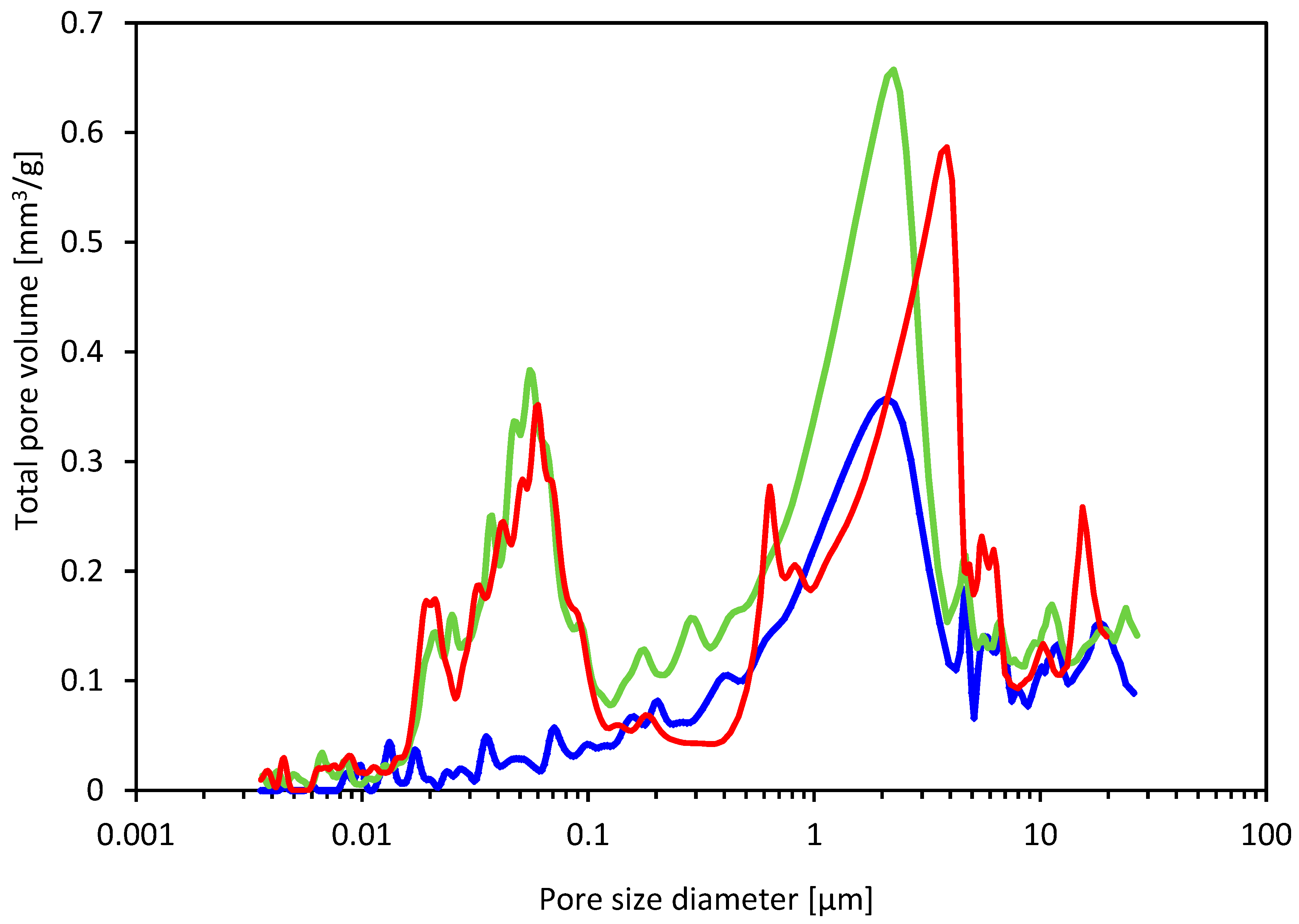
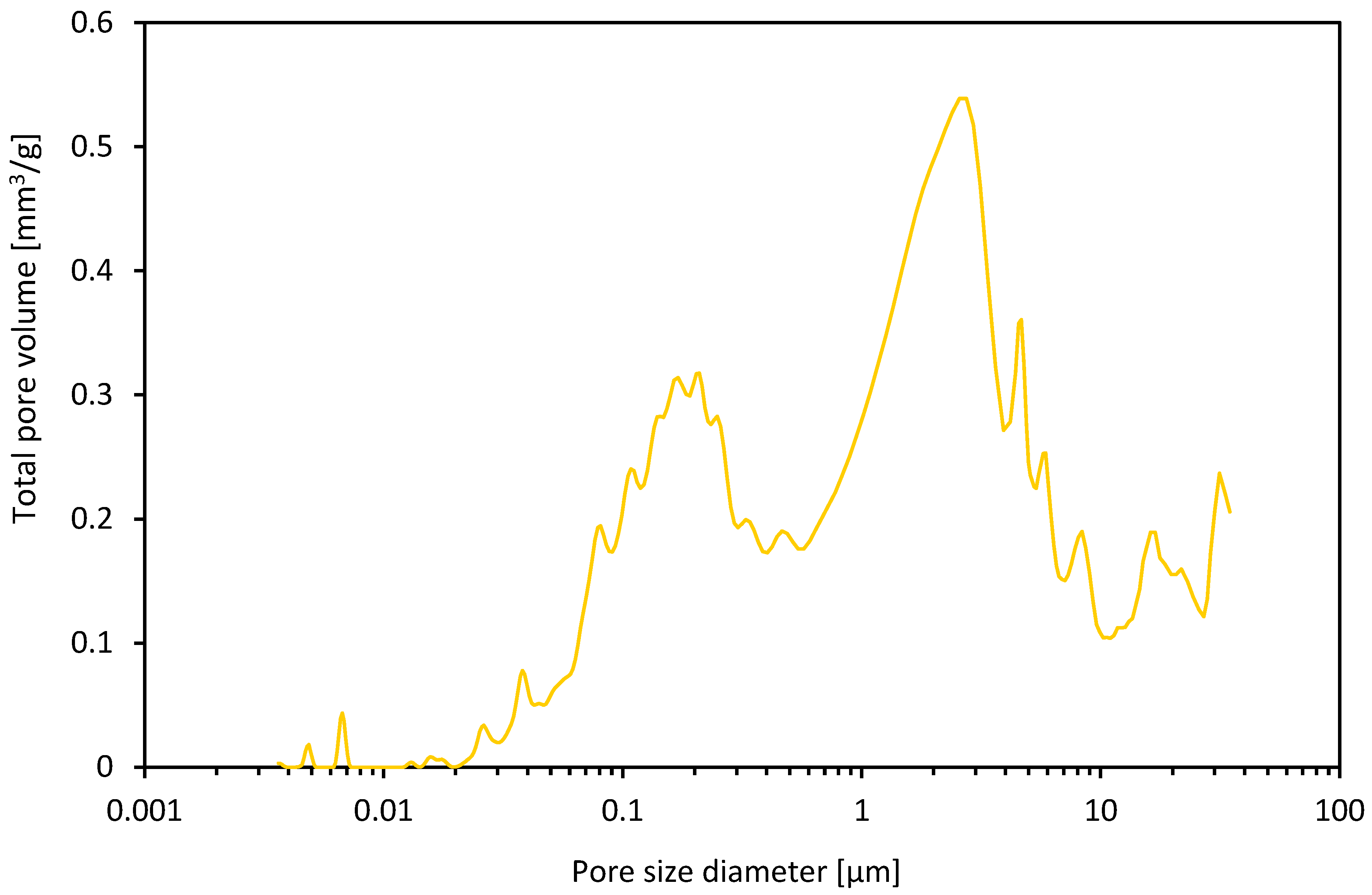
show that the high content of magnesium-containing carbonate phases does not guarantee high desulfurization efficiency. An important role in this case is played by the secondary porosity of the sorbent, determined by the presence of pores with diameters bordering on mesopores and macropores.
Much space is devoted to the mineralogical and petrographic characteristics of the studied magnesites, as we intended to show that both the mineral composition and the structural and textural character of the rock may have a significant impact on the desulfurization efficiency and may be responsible for the reduced sorption capacity of the sorbent.

2. Materials and Methods

The materials for the research were magnesites from Polish deposits located in Lower Silesia–Braszowice, Szklary, Wiry (Table 1 and Figure 1). The magnesite deposits belong to a geological unit called the Fore-Sudetic Block. The magnesite occurs here in serpentinite rocks, forming the Braszowice–Grochowa and Szklary massifs. The serpentinite massifs were formed as a transformation result of the ultrabasic igneous intrusions composed of peridotites and dunnites under the influence of hydrothermal solutions. The tropical climate prevailing in the Tertiary period caused intense chemical weathering of the serpentines, which resulted in, among other products, the formation of magnesite. In these deposits, magnesite takes the form of sockets and veins of varying thickness, which, branching, become dispersed, turning into mesh-like fine veins crossing the serpentine massif [16]. In such an occurrence, magnesite is white, white with a yellow rim, or yellow and brown. The varied color of magnesite is the result of a changeable chemical composition and depends on the degree of weathering of the serpentinite. The different colors depend on the iron content. White magnesite, characterized by high purity, occurs in serpentinite not affected by weathering processes.
Among the mentioned deposits, only the Braszowice deposit is currently exploited. In this case, the samples were taken from the operational mining walls of the “Konstanty” opencast mine. The remaining samples were obtained from the heaps located in the areas of closed mines. For comparison purposes, high-quality lime industrial sorbent was used in parallel studies and was treated as a reference material.
The objective of this research was to determine the role of magnesium in the process of flue gas desulfurization under the conditions of fluidized bed furnaces. Particular attention was paid to the mineralogical and petrographic characteristics of the magnesites used as SO2 sorbents and sulfation reaction products. An attempt was made to:
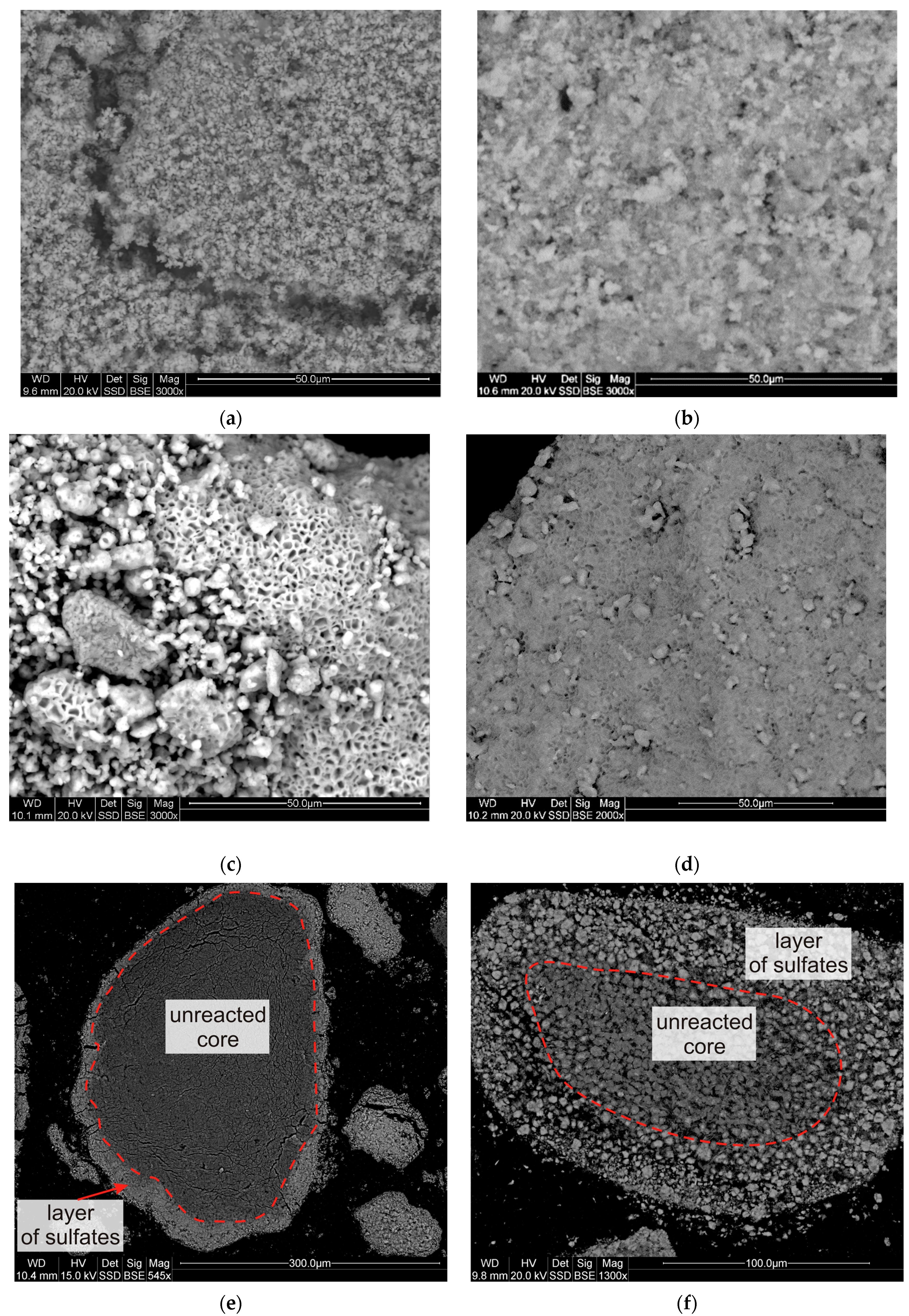
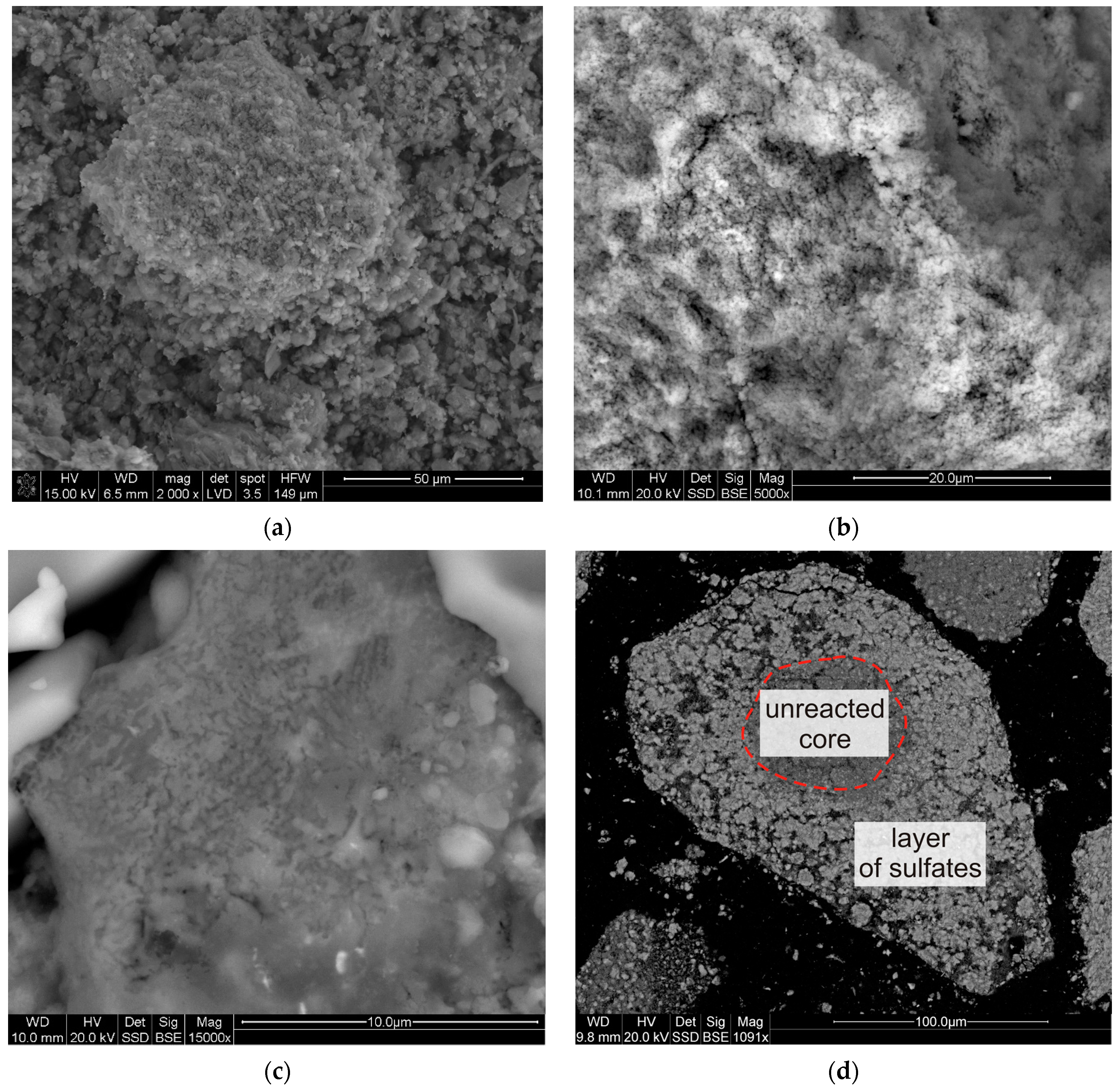
depict the mechanism of SO2 sorption by magnesite.
determine the parameters of the sorbent responsible for the effectiveness of the SO2 binding process.
The results of this research were compared with the results of our earlier research regarding the possibility of using dolomites as SO2 sorbents in fluidized bed combustion conditions [9]. This comparison was possible thanks to the use of the same measurement conditions during the sulfation experiment and the research methodology. Comparing research results with the works of other authors is a great challenge and is often not possible due to the varied conditions of conducting the experiments, incomplete mineralogical characteristics of both the research material (which is of great importance when conducting research with the use of natural raw materials) and sulfation products. The authors’ own experience in the study of this type of sorbents indicates that the use of mineralogical and petrographic research methods will allow, in addition to determining the magnesium content, obtaining a more complete picture of the SO2 sorption mechanism and the impact of sorbent parameters other than chemical composition on the SO2 binding process.
To assess the sorption properties of magnesites, the research methodology developed for the purpose of testing dolomites, presented in [9], was used.
The sulfation experiment was carried out based on the guidelines developed by Ahlstrom Development Laboratory [18]. This method is based on determining two indicators: the reactivity (RI index) and absolute sorption (CI index). The reactivity index determines the ratio of the calcium content (in the case of magnesite studies, magnesium was additionally included) in the sample to the amount of sulfur after the sorption process [Ca + Mg/S moles]. The absolute sorption index, in turn, determines the amount of sulfur sorbed by 1000 g of the sorbent [g S/1000 g of the sorbent]. The SO2 sorption studies were carried out using a material with a particle size of 0.125–0.250 mm. The sulfation experiment was carried out based on a gas-tight retort furnace acting as a fixed bed. The sulfation experiment was carried out in two stages in accordance with the guidelines:
  • Samples were subjected to a decarbonization process at 850 °C for 30 min prior to sulfation. A sample of the sorbent (150 mg) was placed inside the combustion chamber, on a perforated ceramic plate, in such a way that the individual grains of the sorbent were not in contact with each other. In this way, free access of gases to individual sorbent grains was ensured during the experiment. Synthetic air containing 80% N2 and 20% O2 was passed through the samples.
  • Then, a gas containing 1780 ppm of SO2, 3% of O2, 16% of CO2 and N2 was passed through the samples at a speed of 950 mL/second for another 30 min.
In the next stage, the content of absorbed sulfur was determined with an elemental analysis apparatus for carbon, hydrogen, nitrogen and sulfur (Series 628, LECO). The results of the research became the basis for calculating the values of RI and CI indicators according to the formulas:
R I = M S 100 x C a M C a + x M g M M g 1 M C O 2 M C · x C p 100 M S O 3 M S · x S p 100 x S p x S b 100 + M C O 2 M C · x C p · x S b x C b · x S p 10 , 000
C I = 1000 · [ x S p x S b 100 + M C O 2 M C · x C p · x S b x C b · x S p 10 , 000 ] 1 M C O 2 M C · x C p 100 M S O 3 M S · x S p 100
where xCa, xCp, xSp, xCb, xSb—percentages of calcium in the sorbent, carbon in the sorbent after the sulfating process, sulfur after the sulfating process, carbon before the sulfating process and sulfur before the sulfating process, respectively [%]; MS, MCa, MMg, MC, MCO2, MSO3—molar masses of sulfur, calcium, magnesium, carbon, carbon dioxide and sulfur trioxide, respectively [kg/kmol].
To evaluate the sorption capacity, the five-level scale proposed by Ahlstrom Development Laboratory was used (Table 2).
To characterize the parameters affecting the SO2 binding process, the experimental studies were supplemented with:
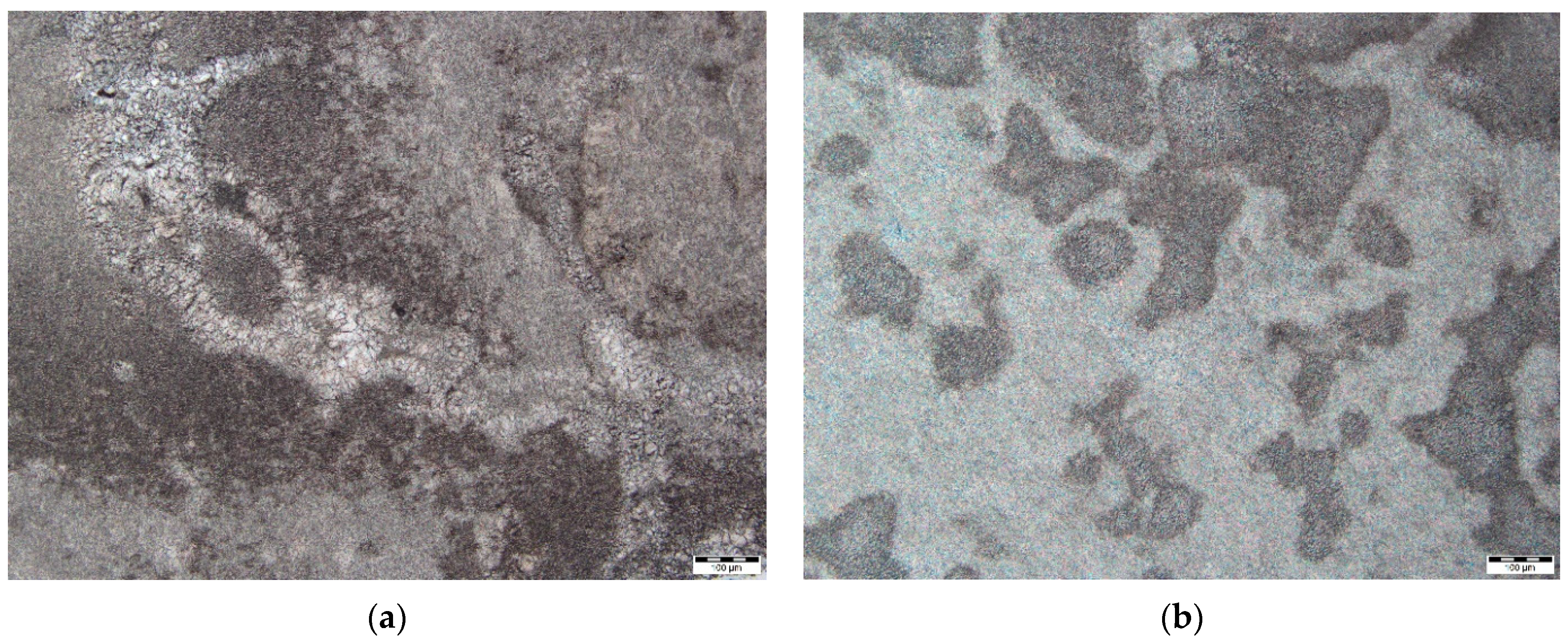
Microscopic observations in polarized transmitted light were made using an Olympus BX-41 (Olympus, Tokyo, Japan) polarizing microscope with an Olympus SC180 camera.
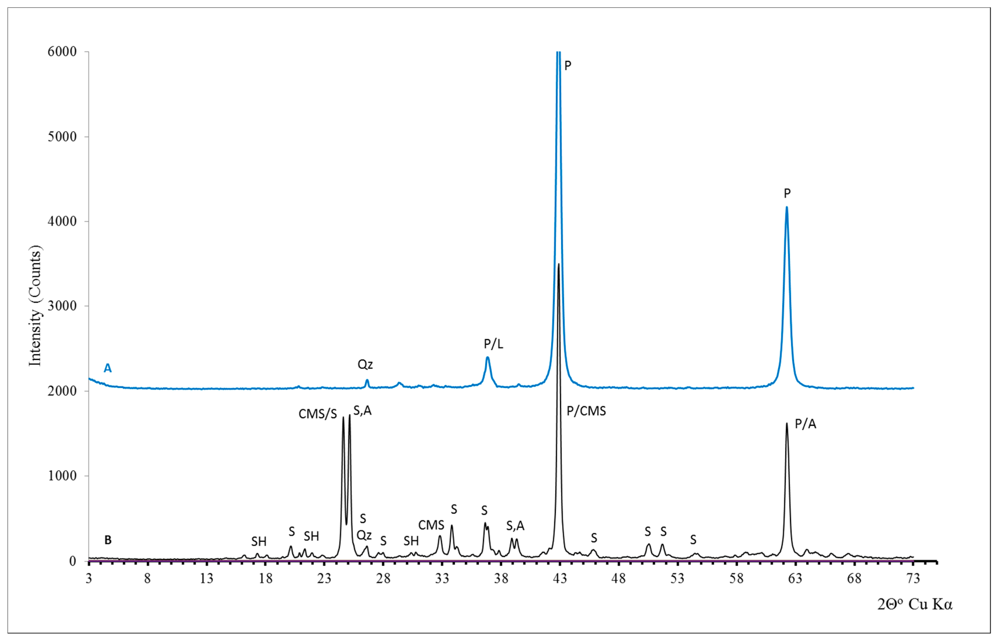
Tests of the phase composition and structural and textural features of natural samples after the decarbonation and sulfation process using X-ray diffraction using the DSH method (MiniFlex 600, Rigaku, Tokyo, Japan) and scanning microscopy (Quanta 200 FEG, FEI, Hillsboro, OR, USA).
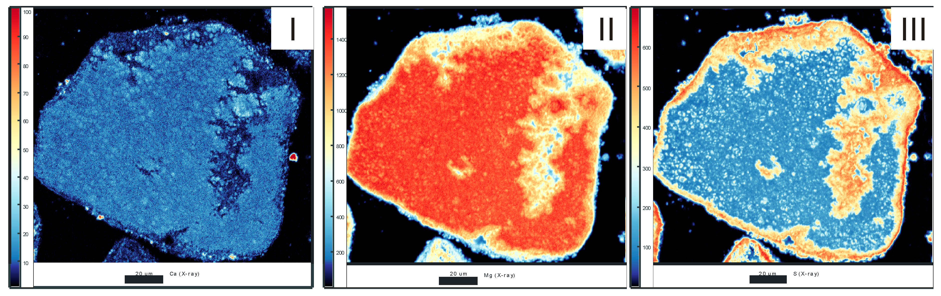
Research of the distribution of Ca, Mg and S within sorbent grains using an electron probe microanalyzer (EPMA) (JEOL Super Probe 8230, Peabody, MA, USA).
Analysis of the main chemical components was performed using instrumental methods, i.e., atomic emission absorption spectroscopy (ICP–OES Plasma 40, PerkinElmer, Waltham, MA, USA) and complexometric titration (determination of MgCO3 and CaCO3).
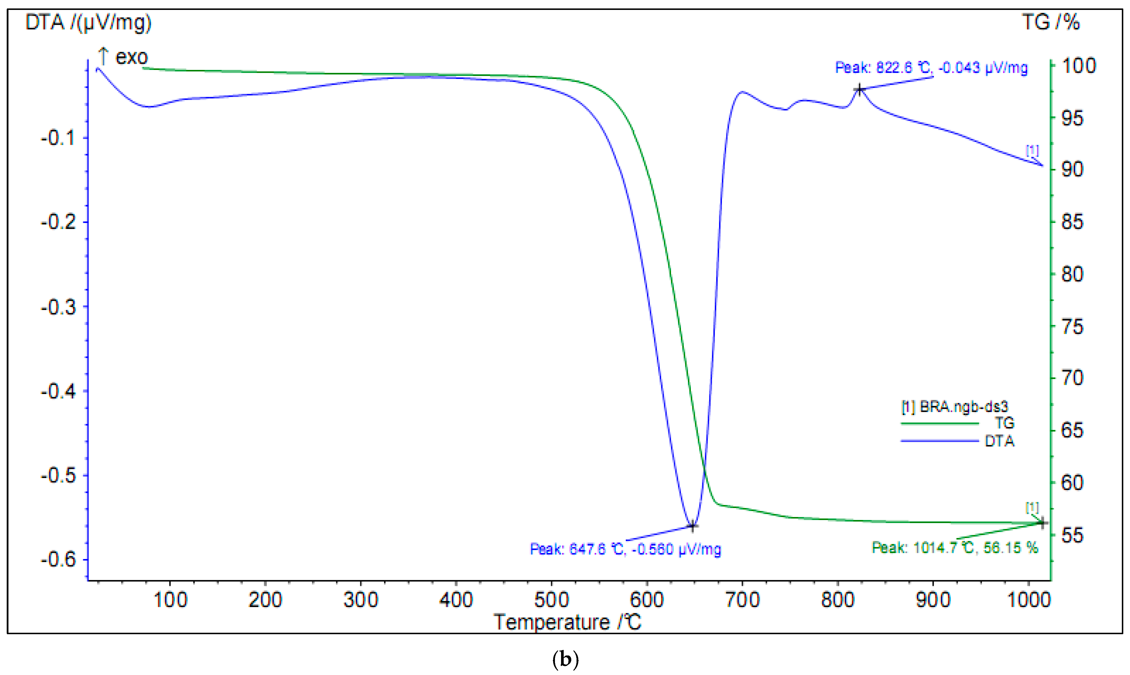
The temperature and course of thermal dissociation of magnesites (STA 449 F3 Jupiter + QMS 403C Aelos, Netzsch, Selb, Germany) were determined with differential derivatographic analysis (DTA) and thermogravimetry (TG). In addition, thermal analyses (TGA/DSC 3+, Mettler Toledo, Greifensee, Switzerland) were performed for the products of the sulfation experiment in order to determine their thermal stability in high-temperature conditions. All measurements were made in an air atmosphere.
A porous texture analysis was performed using a mercury porosimeter. The following porous texture parameters were determined:
  • The coefficient of effective porosity, i.e., the ratio of pore volume to the total volume of the sample [19,20,21,22]:
ϕ = V t o t V b · 100 % = V b V s V b · 100 % = 1 ρ b ρ s · 100 %
where ϕ—coefficient of effective porosity (%); Vtot—total volume of mercury in the pores (mL); Vb—external volume (mL); Vs—skeleton volume (mL); ρb—bulk density (g/mL); ρs—skeletal density (g/mL).
2.
The specific surface area of porous space, i.e., the pore area in relation to the sample unit mass. This parameter characterizes the flow resistance of reservoir media in the porous medium. The specific surface area, assuming the reversibility of the injection process, is determined based on the obtained pore volume according to the following equation [19,22]:
A = 1 γ c o s θ 0 V P d V
where A—total surface area of porous space (m2/g); dV—partial pore volume corresponding to the given capillary pressure (m3); P—capillary pressure (psi); γ—surface tension of mercury (dyna/cm); θ—contact angle (°).
The study of the specific surface area and porosity was also carried out using the low-temperature nitrogen sorption method. An ASAP 2020 device for precise sorption measurements (Micromeritics, Norcross, GA, USA) was used for the analysis. Immediately before measurement, the samples were dried at 105 °C for 1 h, and then annealed under vacuum at 150 °C for 12 h. The specific surface area (SBET) was determined based on low-temperature nitrogen adsorption isotherms at −196 °C according to the Brunauer–Emmet–Teller (BET) method [23]. The total pore volume (Vtot) was also calculated for the relative pressure p/p0 = 0.99. In addition, we calculated:
  • the micropore volume (VmikDR), for pores with a width of less than 2 nm, according to the Dubinin–Radushkevich method, and their share in the total pore volume VmikDR/Vtot0.99;
  • the mesopore volume (VmezBJH), for pores with a diameter above 2 nm and below 50 nm, according to the Barrett–Joyner–Halenda (BJH) method, and their share in the total pore volume (VmezBJH/Vtot0.99);
  • the macropore volume (Vmak), for pores with a diameter above 50 nm, calculated by subtracting the volume of micro- and mesopores from the total pore volume: Vmak=Vtot0.99 − (VmikDR + VmezBJH), and their share in the total pore volume Vmak/Vtot0.99.
The analyses were performed in accordance with standards: ISO 9277:2010 [24], ISO 15901-2:2006 [25] and ISO 15901-3:2007 [26].

3. Results and Discussion

3.1. Mineralogical and Petrographical Characters and Chemical Composition of Magnesites

The studied magnesites are generally microcrystalline rocks. They are made of magnesite (MgCO3) crystals with a size of 2–5 μm (Figure 2 and Figure 3).
In the magnesites from the Szklary and Wiry deposits, there are numerous cavities and pores, formed as a result of the MgCO3 leaching processes. They were filled with larger (microsparite and sparite) magnesite crystals (Figure 2 and Figure 3). These types of fillings or areas in their immediate vicinity are often pigmented with iron compounds and their texture is clearly porous (Figure 2 and Figure 3).
The magnesite from the Braszowice deposit is characterized by a colomorphic structure. The microcrystalline and cryptocrystalline created MgCO3 forms irregular laminae of varying thickness from 0.05 to 0.5 mm and a complicated course, highlighted by a color change caused by the presence of iron compounds (Figure 4). Within the laminas, a gradational increase in the size of magnesite crystals to several μm is observed. The texture of the magnesite from Braszowice is massive. The pore space between the magnesite crystals is filled with clay minerals; unfilled pores are rare. They can be seen between successive laminates of magnesite. Usually within them, there are minerals from the serpentine group, most often a fibrous clinochrysotile.
In the studied magnesites, a silification process was observed, manifested by the presence of chalcedony aggregates and microcrystalline quartz within the rock pores.
The content of non-carbonate minerals in the rocks was determined by means of quantitative microscopic analysis. In the magnesites from Wiry, their presence was estimated at about 5% of the rock volume. These are mainly the above-mentioned minerals from the silica group. In the magnesites from Szklary and Braszowice, the share of non-carbonate minerals is higher, on the order of 10 and 12% by volume. In addition to quartz and chalcedony, minerals from the serpentine group have been identified, occurring within rock pores that are part of the karst system (Figure 2b). It is believed that they were transported there via karst solutions. In the magnesites from Braszowice, the pore space of the rock is additionally filled with clay minerals.
In the mineral composition of the examined rocks, the presence of ferruginous type magnesite was additionally confirmed by diffraction tests (Table 3 and Figure 5). In the samples of rocks from the Szklary and Wiry deposits, the addition of dolomite (up to 5% of the rock volume) and trace amounts of calcite were identified, mainly in the case of magnesite from Szklary (up to 3% of the rock volume). Clay minerals of the illite/montmorillonite type were identified in the composition of the magnesites from Szklary and Braszowice. In the magnesite from Szklary, sepiolite, which is a typical product of serpentinite conversion under the influence of weathering processes, and talc, formed as a hydrothermal olivine and pyroxene transformation result, also marked their presence.
The chemical composition of the investigated magnesites reflects their phase composition. It shows a slight quantitative variation in terms of the key components for the course of SO2 sorption content, such as CaCO3 and MgCO3 (Table 4).
The highest total content of carbonate components is characterized by magnesite from Wiry (89.36% wt). In the case of other magnesites, the contents are lower: 82.98% wt. for magnesite from the Braszowice and 84.2% wt. for magnesite from the Szklary deposit. A small share of calcium carbonate (1.0–5.23% wt.) in the composition of individual samples is noteworthy. The content of SiO2 is at a similar level of 5.42–6.89% wt. Despite the small share of Al2O3 (0.22–3.14% wt.) in the magnesite composition, the aluminum content should be considered varied. The highest content of Al2O3 was found in magnesite from Braszowice, which, in combination with the highest content of SiO2, K2O and Na2O, confirms the highest share of non-carbonate components in the mineral composition of the rock, demonstrated by microscopic examination.

3.2. The Sorption Efficiency and MgO Participation in the SO2 Binding Process

Table 5 shows the average values of reactivity and sorption indicators for individual magnesites and the industrial sorbent. In the case of the studied magnesites, the RI and CI values are within a wide range (RI 2.43–6.1 kmol Ca + Mg/kmol S; CI 122–17 gS/kg of sorbent), which results in a differentiated assessment of sorption properties: from excellent—magnesite from the Wiry deposit, through very good—magnesite from the Szklary deposit, to low quality—magnesite from the Braszowice deposit. Comparing the RI and CI values of the tested magnesites with a high-class industrial sorbent, it should be noted that the magnesite from Wiry, despite a clearly lower content of carbonate components (78.90% by weight) compared to the industrial sorbent (98.10% wt.), shows effective sorption at a comparable level. The magnesite from Szklary has a slightly lower sorption efficiency compared to the magnesite from Wiry, which may be caused by a lower share of carbonate components in the chemical composition of this magnesite (69.59% wt.). The RI and CI values obtained for the magnesites from Wiry and Szklary indicate the effective participation of magnesium in the SO2 binding process. Why does the magnesite from Braszowice, despite the higher content of carbonate components compared to the magnesite from Wiry (72.88% wt.), show an extremely low sorption efficiency? It should be assumed that the high content of carbonate components is not a guarantee of high efficiency of SO2 sorption in the analyzed measurement conditions.
The results of the X-ray analysis confirm the participation of magnesium in the SO2 binding process. The phase composition of magnesite from Wiry samples after the sulfation process, presented in the diffractograms (Figure 5), shows that the magnesium (MgO) and calcium (CaO) oxides formed at 850 °C (Figure 6A) take an active part in the SO2 binding process to form the sulfate phases: CaSO4, MgSO4 and CaMg2(SO4)3 (Figure 6B). The presence of unreacted MgO residues cannot be ruled out, since diffraction lines with values of 2θ = 42.88°, d = 2.1072 Å and 2θ = 62.27°, d = 1.2898 Å are characteristic for both MgO and CaMg2(SO4)3 (first line) and CaSO4 (second line).
To better illustrate the participation of magnesium in the SO2 binding process, distribution maps of Ca, Mg and S were made on the cross-sectional surface of sorbent grains after the sulfation process using an electron probe microanalyzer (EMPA) (Figure 7). The photos show that sulfur accumulates over the entire cross-sectional area of the grain. However, the largest amounts were bound in the near-surface zone and on the outer surface of the grains, as well as along the crack running through the grain. It should be noted that the gap was not covered with desulfurization products during the sulfation process and constituted a diffusion channel for SO2 into the sorbent interior.
One of the main arguments given against the use of magnesites as SO2 sorbents in fluidized bed combustion technology is the thermal instability of magnesium sulfates in the temperature conditions characteristic of this technology. In order to investigate the range of thermal stability of the produced sulfates, derivatographic tests were performed. The thermal curves of TG and DTG of magnesite from Wiry after the sulfation process presented in the figure show that the thermal decomposition of MgSO4 begins at a temperature of about 950 °C, and the highest rate of this process occurs at a temperature of about 1050 °C. There is also a faint thermal effect at about 1120 °C, which corresponds to the thermal decomposition of CaMg2(SO4)3 (Figure 8). This indicates different properties of sulfates (containing magnesium in their structure), formed in high-temperature conditions in relation to sulfates with an analogous structure, formed from aqueous solutions [27].
One of the parameters responsible for the sorption efficiency and the sorbent conversion degree is the thermal dissociation temperature of the carbonate phases involved in the SO2 sorption process [28]. The course of the decarbonation process of magnesites from Wiry and Braszowice was investigated to determine the impact of the mineral composition on it. The thermal effects of the heating of magnesites and the associated mass losses are shown in Table 6 and Figure 9. The thermal decomposition of magnesite from Wiry begins at about 410 °C and is visible as a strong endothermic effect reaching its extreme at 620 °C. At a slightly higher temperature, dolomite decomposes, visible as another endothermic peak from the extreme at 757 °C. It is usually two-stage, but in the case of small amounts of this mineral in the sample, only one endothermic effect is visible during thermal dissociation. At 850 °C, the degree of decarbonation is high and amounts to 50.45% wt. Further heating of the sample does not cause significant changes in mass, because in the temperature range of 850–1000 °C, the mass loss is only 0.02% by wt. Thermal decomposition of magnesite from Braszowice proceeds in a similar way. The process of magnesite decomposition begins at 500 °C and ends at 648 °C with a weight loss of 41.29% wt. At slightly higher temperatures, decomposition of dolomite (738 °C) and calcite (800 °C) is observed. There is also an exothermic reaction associated with the formation of secondary calcite (822.6 °C), which then undergoes thermal dissociation. The decomposition of this type of carbonate phase is accompanied by a negligible mass loss of 1.23% by weight. At 850 °C, the degree of decarbonation is 43.73% wt. Further heating of the sample does not cause significant changes in mass, because in the temperature range of 850–1000 °C, mass loss is only 0.12% by weight. Differences in the mineral composition of the magnesites from Wiry and Braszowice have no significant effect on the course of the carbonation process, apart from slightly lower mass losses during heating, which is related to the lower share of carbonate phases in the magnesite from Braszowice.

3.3. Porosity of Desulfurization Products and SO2 Sorption Efficiency

The surfaces of decarbonated and sulfated grains, as well as the cross-sections through the sulfated magnesite grains from Wiry and Szklary, presented in Figure 10, make it possible to analyze the SO2 sorption process. The distribution of sulfur inside the sorbent grains is related to the secondary porosity created during the decarbonatization process (Figure 10a,b). This porosity determines the texture of the sulfation products on the sorbent grain surface (Figure 10c,d). The porous texture of the produced sulfates (Figure 10c) ensures the continuity of the SO2 sorption process throughout the sulfation period and is responsible for a higher degree of sorbent grain utilization (Figure 10e). If poorly porous sulfates are produced during the sulfation reaction, as in the case of magnesite from Szklary (Figure 10d), the SO2 sorption process can be stopped earlier. In such cases, the grains contain a larger unreacted MgO/CaO core (Figure 10e). The sorption efficiency of such a grain and its degree of conversion is lower. Analyzing grain cross-sections, it was observed that in the case of magnesite from Wiry, the sorption process was more effective. Thanks to the porosity visible in Figure 10c, SO2 penetrated the grain almost in its entire volume.
The surface morphology of the magnesite grains from Braszowice, visible in Figure 11a, does not differ in any special way from other magnesites. Despite this, the surface of the grains after the decarbonization process is differently shaped. It has been expanded to a lot greater extent than the magnesites from Wiry and Szklary. The pores formed as a result of thermal dissociation appear to be much smaller (Figure 11b). During the sulfation process, the surface of the grains was covered with massive, non-porous sulfate, which led to stopping the SO2 sorption process in the initial stage and resulted in a low degree of their conversion (Figure 11d).
To determine the influence of the sorbent texture parameters on the SO2 sorption efficiency, tests of the specific surface area and porosity of magnesites from Wiry and Braszowice were carried out using low-temperature nitrogen sorption and mercury porosimeter. The following were tested: natural samples and samples after the decarbonization and sulfation processes. The test results were compared with an industrial sorbent (Table 7).
The analysis of the porous texture parameters of the tested samples indicates that the SO2 binding efficiency does not directly depend on the value of the sorbent specific surface area. Magnesite from Braszowice has the largest surface area: SBET—12.9 m2/g, SPOR—2.28 m2/g before the decarbonation process and SBET—21.97 m2/g, SPOR—5.54 m2/g after the decarbonization process (Table 6). In this case, the porosity and, above all, the diameters of the pores formed during the sorbent decarbonization process are important. The analysis of the porosity of magnesite from Braszowice in connection with the low sorption efficiency indicates that the presence of micropores (i.e., pores below 2 nm) is not desirable. The specific surface of the magnesite from Braszowice was developed mainly based on micropores (Vmik—0.121 cm3; Vmik/Vtot—73.3%). As a result, the effective porosity of this magnesite is lower (Table 6). The distribution of pore volume as a function of their diameter in the magnesites from Braszowice, presented in Figure 12, shows that pores with diameters below 0.1 μm, which were formed in the decarbonization process (green line), were not filled in the sulfation process (red line). It should be assumed that they do not participate in the SO2 sorption process. In the case of magnesite from Wiry, the diameters of the pores are above 0.1 µm (Figure 13). The low efficiency of SO2 sorption of magnesite from Braszowice is related to the unfavorable nature of the porous texture, i.e., a high proportion of pores in the range of micropores and smaller mesopores (below 0.1 µm).

4. Conclusions

The magnesites, as well as limestones and dolomites, under conditions of fluidized bed combustion technology can act as SO2 sorbents. The SO2 sorption efficiency of magnesites corresponds to that of limestone and is lower than that of dolomites. However, it should be mentioned that dolomites show the highest sorption efficiency among carbonate rocks [9].
Magnesium as MgO takes an active part in binding SO2 to form MgSO4 and CaMg2(SO4)3 sulfate phases. The resulting sulfation products are stable in the temperature conditions characteristic of the fluidized bed combustion technology. The decomposition of MgSO4 begins at a temperature of approx. 950 °C, and the highest rate of this process occurs at approx. 1050 °C. The decomposition of CaMg2(SO4)3 is observed at a temperature of approx. 1120 °C.
The high content of carbonate components does not guarantee high desulfurization efficiency. In the SO2 binding process, the textural parameters of the sorbent are important, especially the diameter of the pores formed during the decarbonation process. The presence of pores below 0.1 µm is not desirable. Pores with such diameters do not participate in the SO2 capture process. Their presence contributes to the formation of a massive layer of sulfates on the outer surface of the formation of sorbent grains and is responsible for the low degree of sorbent utilization and the high content of unreacted portions of MgO and CaO in the composition of desulfurization products. In real conditions, where decarbonization and sulfation processes occur almost simultaneously, it is also responsible for the presence of undissociated portions of MgCO3 and CaCO3. The process of SO2 sorption with the use of carbonate sorbents (magnesites, limestones, dolomites) is based on a typical non-catalytic reaction in the gas–solid system [4]. Despite the fact that during the laboratory tests, the sulfation process was applied to previously decarbonated sorbents, and the process itself was carried out in stable conditions (temperature, gas flow rate), the SO2 binding process was not uniform. The conditions changed due to the gradual consumption of the sorbent. The porosity of the sorbent had a decisive influence on the dynamics of such changes. In real conditions of fluidized bed furnaces, where the processes of decarbonization and sulfation run in parallel, more dynamic changes during the sulfation reaction should be expected [29].
The course of the sulfation process in real conditions can be divided into at least three stages. The effectiveness of SO2 binding occurring during individual stages will be shaped by the porosity of the sorbent [30,31]. First, through the primary pores, related to the textural nature of the rock, and then through the secondary ones, formed during decarbonation.
1st stage—simultaneous diffusion of SO2 into the sorbent grains and CO2 from the inside of the sorbent grains (mainly through primary pores related to rock porosity and secondary pores formed in high-temperature conditions because of carbonate decomposition) combined with SO2 adsorption on the outer surface of the sorbent grains;
2nd stage—simultaneous adsorption of SO2 mainly on the external, decarbonated surface of the sorbent grains and on the internal surface of the pores formed during the decarbonation process, combined with the release of CO2 from the inside of the sorbent grains;
3rd stage—diffusion of SO2 inside the sorbent grains through the layers of desulfurization products formed on their outer surface.
In the initial phase of sulfation, the gas–solid reaction process proceeds rapidly. SO2 binding occurs most intensively on the outer surface of the sorbent grains and leads to the formation of a layer of desulfurization products. Over time, SO2 diffusion through the layer of the desulfurization product begins to play a greater role, and the SO2 binding process is transferred to the interior of the sorbent grains [32]. It is slower, because the product of desulfurization both on the outer surface of the grains and on the inner surfaces of the pores formed during decarbonation hinders the flow of SO2 by blocking the sorbent pores [29,33]. If the sorbent secondary porosity is developed with smaller-diameter pores (in the range of micropores and smaller mesopores), SO2 diffusion into the interior of sorbent grains will be stopped. The SO2 binding process will take place only on the outer surface of the sorbent grains until the free portions of CaO and MgO are reached. In extreme cases, if the share of larger pores is very limited, the diffusion of SO2 into the sorbent grains and CO2 from the inside of the sorbent grains will already be stopped in the initial phase of desulfurization. This will result in the presence of not only unreacted portions of MgO, but also undecomposed MgCO3.
In evaluating the sorption properties of the investigated magnesites, the presence of clay minerals cannot be ignored. Clay minerals should not be treated simply as non-reactive ballast, not involved in SO2 sorption. A significant content of illite and montmorillonite in magnesite from Braszowice unfavorably shapes the texture of the sorbent, which additionally affects the low efficiency of SO2 binding. Clay minerals, by sealing the pore space of the rock, additionally contributed to an increase in the share of micropores and a decrease in the effective porosity value. In addition, they have a negative impact on the decarbonation process. The processes of dehydration and dehydroxylation of illite and montmorillonite occurring during heating caused the effect of pores “shrinking” [34]. This is reflected in the values of the sorbent texture parameters after the decarbonatization process (high proportion of micropores, low value of effective porosity).

Author Contributions

Conceptualization. E.H.; Formal analysis. E.H. and M.S.; Investigation. E.H., M.S. and T.R.; Methodology. E.H. and M.S.; Resources. E.H. and M.S.; Supervision. T.R.; Writing—original draft preparation. E.H.; Visualization—E.H. and M.S.; Writing—review & editing. E.H., T.R. and M.S. All authors have read and agreed to the published version of the manuscript.

Funding

This research received no external funding.

Data Availability Statement

Not applicable.

Acknowledgments

This work was carried out in the statutory research of the Department of Mineralogy, Petrography and Geochemistry of AGH in Krakow and the Institute of Mineral and Energy Economy of the Polish Academy of Sciences in Krakow. The research was made with the support of the apparatus of the Center of Energy AGH.

Conflicts of Interest

The authors declare no conflict of interest.

References

  1. Urbanek, A.; Kumanowski, K. Desulfurization of flue gases by wet magnesium method developed by the Technical University of Warsaw. Air Prot. Waste Probl. 2002, 36, 53–60. (In Polish) [Google Scholar]
  2. Hanif, M.A.; Ibrahim, N.; Abdul Jalil, A. Sulfur dioxide removal: An overview of regenerative flue gas desulfurization and factors affecting desulfurization capacity and sorbent regeneration. Environ. Sci. Pollut. Res. 2020, 27, 27515–27540. [Google Scholar] [CrossRef]
  3. De las Obras-Loscertales, M.; Rufas, A.; de Diego, L.F.; García-Labiano, F.; Gayán, P.; Abad, A.; Adánez, J. Morphological analysis of sulfated Ca-based sorbents under conditions corresponding to oxy-fuel fluidized bed combustion. Fuel 2015, 162, 264–270. [Google Scholar] [CrossRef] [Green Version]
  4. Cheng, L.; Chen, B.; Liu, N.; Luo, Z.; Cen, K. Effect of characteristic of sorbents on their sulfur capture capability at a fluidized bed condition. Fuel 2006, 83, 925–932. [Google Scholar] [CrossRef]
  5. Zevenhoven, R.; Yrjas, P.; Hupa, M. Sulfur dioxide capture under PFBC conditions: The influence of sorbent particle structure. Fuel 1998, 77, 285–292. [Google Scholar] [CrossRef]
  6. De las Obras-Loscertales, M.; de Diego, L.F.; García-Labiano, F.; Rufas, A.; Abad, A.; Gayán, P.; Adánez, J. Sulfur retention in an oxyfuel bubbling fluidized bed combustor: Effect of coal rank. type of sorbent and O2/CO2 ratio. Fuel 2014, 137, 384–392. [Google Scholar] [CrossRef] [Green Version]
  7. Anthony, E.J.; Granatstein, D.L. Sulfation phenomena in fluidized bed combustion systems. Prog. Energy Combust. Sci. 2001, 27, 215–236. [Google Scholar] [CrossRef]
  8. Al-Shawabkeh, A.; Matsuda, H.; Hasatani, M. Dry, high-temperature De-SO2 and De-H2S via treated calcium-based materials. Energy Convers. Manag. 1997, 38, 138–139. [Google Scholar] [CrossRef]
  9. Hycnar, E.; Ratajczak, T.; Sęk, M. Dolomites as SO2 Sorbents in Fluid Combustion Technology. Resources 2020, 9, 121. [Google Scholar] [CrossRef]
  10. Stanienda-Pilecki, K.J. The Use of Limestones Built of Carbonate Phases with Increased Mg Content in Processes of Flue Gas Desulfurization. Minerals 2021, 11, 1044. [Google Scholar] [CrossRef]
  11. Crnkovic, P.M.; Milioli, F.E.; Pagliuso, J.D. Kinetics study of the SO2 sorption by Brazilian dolomite using thermogravimetry. Thermochim. Acta 2006, 447, 161–166. [Google Scholar] [CrossRef]
  12. Kaljuvee, T.; Trikkel, A.; Kuusik, R.; Bender, V. The role of MgO in the binding of SO2 by lime-containing materials. J. Therm. Anal. Calorim. 2005, 80, 591–597. [Google Scholar] [CrossRef]
  13. Anthony, E.J.; Jia, L.; Charland, J.-P.; Laursen, K. Agglomeration behavior of dolomitic sorbents during long-term sulfation. Energy Fuel 2003, 17, 348–353. [Google Scholar] [CrossRef]
  14. Kaljuvee, T.; Kuusik, R.; Uibu, M. Behavior of magnesium compounds at sulfation of lime-containing sorbents. In Proceedings of the Sixth International Symposium and Exhibition on Environmental Contamination in Central and Eastern Europe and the Commonwealth of Independent States, Prague, Czech Republic, 1–4 September 2003. [Google Scholar]
  15. Pozzi, M.; Stanienda, K. The influence of the contents of magnesium of the Triasic limestones from “Tarnów Opolski” deposit on their sorption properties in desulphurization technology. Sci. Pap. Sil. Univ. Technol. Min. 2000, 246, 427–437. (In Polish) [Google Scholar]
  16. Stefanicka, M.; Pierzga, A.; Majchrzak, W. Selected aspects of rational “Braszowice” magnesite deposits management. Min. Sci. Miner. Aggreg. 2016, 23, 167–176. [Google Scholar] [CrossRef]
  17. Karnkowski, P.H. Tectonic subdivision of Poland: Polish lowlands. Pol. Geol. Rev. 2008, 56, 895–903. [Google Scholar]
  18. Ahlstrom Pyropower Reactivity Index. Ahlstrom Pyropower. Technical Paper 1995. Available online: http://www.ahlstrom.com (accessed on 1 June 2007).
  19. Such, P. The pore space investigations for geological and engineering purposes. Sci. Work. Inst. Oil Gas Min. 2000, 104, 96. (In Polish) [Google Scholar]
  20. Such, P. An application of mercury porosimeter in pore space investigations. Sci. Work. Inst. Oil Gas Min. 2002, 113, 86. (In Polish) [Google Scholar]
  21. AutoPore IV 9520 Operator’s Manual V1.09. Micromeritics Instrument Corporation. 2008. Available online: https://www.micromeritics.com/Repository/Files/AUTOPORE_BROCHURE.pdf (accessed on 10 January 2023).
  22. Rootare, H.M.; Prezlow, C.F. Surface areas from mercury porosimetry measurements. J. Phys. Chem. 1967, 71, 2733–2736. [Google Scholar] [CrossRef]
  23. Klobes, P.; Meyer, K.; Munro, R.G. Porosity and Specific Surface Area Measurements for Solid Materials; NIST: Washington, DC, USA, 2006; p. 79. Available online: https://tsapps.nist.gov/publication/get_pdf.cfm?pub_id=854263 (accessed on 12 March 2021).
  24. ISO 9277:2010; Determination of the Specific Surface Area of Solids by Gas Adsorption—BET Method. ISO: Geneva, Switzerland, 2010; p. 24.
  25. ISO 15901-2:2006; Pore Size Distribution and Porosity of Solid Materials by Mercury Porosimetry and Gas Adsorption—Part 2: Analysis of Mesopores and Macropores by Gas Adsorption. ISO: Geneva, Switzerland, 2006; p. 30.
  26. ISO 15901-3:2007; Pore Size Distribution and Porosity of Solid Materials by Mercury Porosimetry and Gas Adsorption—Part 3: Analysis of Micropores by Gas Adsorption. ISO: Geneva, Switzerland, 2007; p. 27.
  27. Stoch, L. Thermal methods. In Research Methods of Minerals and Rocks; Żabiński, B.A., Ed.; Warsaw Geological Publishing House: Warsaw, Poland, 1988; pp. 352–444. (In Polish) [Google Scholar]
  28. Hycnar, E. The structural and textural characteristics of limestones and the effectiveness of SO2 sorption in fluidized bed conditions. Mineral. Resour. Manag. 2018, 34, 5–24. [Google Scholar] [CrossRef]
  29. Li, D.; Ke, X.; Kim, M.; Cai, R.; Yang, H.; Zhang, M.; Jeon, C.H. Attrition, and product layer development of limestone during simultaneous calcination and sulfation in a fluidized bed reactor. Fuel 2021, 293, 120280. [Google Scholar] [CrossRef]
  30. Bai, Y.J.; Chen, M.Q.; Li, Q.H.; Huang, Y.W. Sulfation performance of CaO under circulating fluidized bed combustion-like condition. J. Therm. Anal. Calorim. 2020, 142, 1031–1042. [Google Scholar] [CrossRef]
  31. Montagnaro, F.; Salatino, P.; Scala, F. The influence of temperature on limestone sulfation and attrition under fluidized bed combustion conditions. Exp. Therm. Fluid Sci. 2010, 34, 352–358. [Google Scholar] [CrossRef]
  32. Wichliński, M.; Kobyłecki, R. The effect of porosity on the reactivity of calcium sorbents. Mineralogia 2020, 51, 37–45. [Google Scholar] [CrossRef]
  33. Duo, W.; Laursen, K.; Lim, J.; Grace, J. Crystallization and fracture: Formation of product layers in sulfation of calcined limestone. Powder Technol. 2000, 111, 154–167. [Google Scholar] [CrossRef]
  34. Cordero, J.; Alonso, M. Modelling of the kinetics of sulphation of CaO particles under CaL reactor conditions. Fuel 2015, 150, 501–511. [Google Scholar] [CrossRef] [Green Version]
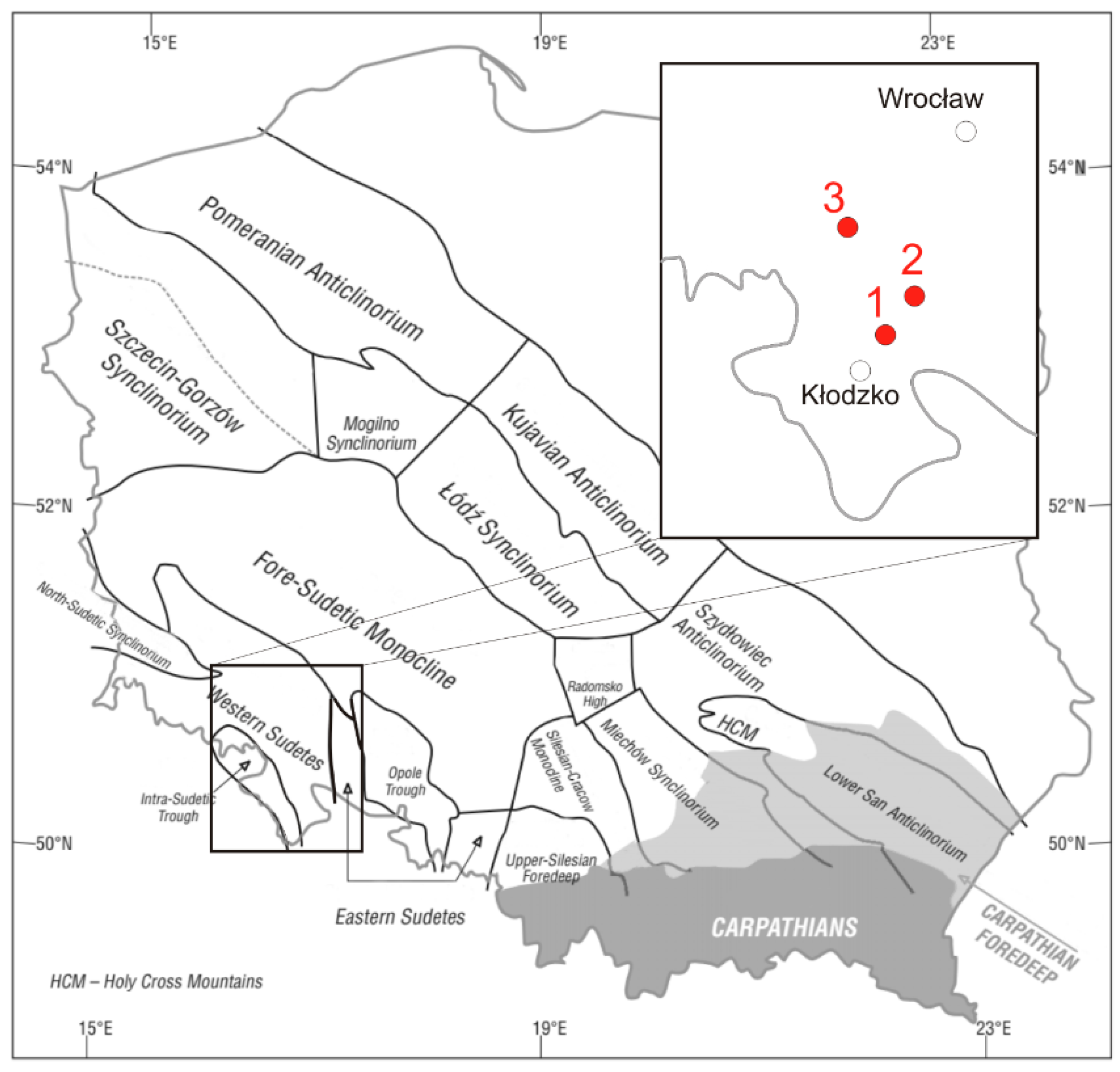
Figure 1. Locations of magnesite deposits from which materials were collected for this research, against the background of the main tectonic units on the sub-Cenozoic surface of Poland [17]. 1—Szklary deposit; 2—Wiry deposit; 3—Braszowice deposit.
Minerals 13 00442 g001
Figure 2. Magnesite from the Wiry deposit. (a,b) Filled with magnesite cement and dark areas pigmented with iron compounds.
Minerals 13 00442 g002
Figure 3. Magnesite from the Szklary deposit. (a) Rock pores filled with magnesite cement and dark-colored areas pigmented with iron compounds. (b) Karst pores partially filled with minerals from the serpentine group, sparite crystals of magnesite.
Minerals 13 00442 g003
Figure 4. Magnesite from the Braszowice deposit, showing irregular lamination and empty pores.
Minerals 13 00442 g004
Figure 5. Phase compositions of magnesite from the Braszowice deposit (MgBra), Szklary deposit (MgSz) and Wiry deposit (MgW) are shown in the diffraction patterns. Explanations: Mnt—montmorillonite (Na,Ca)0,3(Al,Mg)2Si4O10(OH)2·nH2O); Sep—sepiolite (Mg4(Si6O15)(OH)2·6H2O); Tlc—talc (Mg3Si4O10(OH)2); Ctl—clinochrysotile (Mg3(Si2O5)(OH)4); Ilt—illite (K0.65Al2.0[Al0.65Si3.35O10](OH)2); Qz—quartz (SiO2); Mgs—magnesite (MgCO3); Fmgs—ferroan magnesite ((Mg,Fe)CO3); Cal—Calcite (CaCO3); Dol—dolomite (CaMg(CO3)2).
Minerals 13 00442 g005
Figure 6. Phase compositions of the Wiry deposit: (A) after the decarbonization process (–); (B) after the sulfation process (–). Explanations: Qz—quartz (SiO2); P—periclase (MgO); L—lime (CaO); SH—magnesium sulfate hydrate (MgSOH2O); S—magnesium sulfate (MgSO4); CMS—calcium magnesium sulfate (CaMg3(SO4)4); A—anhydrite (CaSO4).
Minerals 13 00442 g006
Figure 7. Sample of magnesite from Wiry after the sulfation process. Distribution maps of Ca (I), Mg (II) and S (III) in the cross section of the sorbent grain (EMPA).
Minerals 13 00442 g007
Figure 8. TG and DTG thermal curves of magnesite sulfation products from the Wiry deposit.
Minerals 13 00442 g008
Figure 9. Thermal curves (DTA and TG), showing the course of the magnesite thermal dissociation process: (a) from the Wiry deposit; (b) from the Braszowice deposit.
Minerals 13 00442 g009aMinerals 13 00442 g009b
Figure 10. Magnesites from Wiry (ac) and Szklary (df): (a,b) samples after the decarbonation process; (cf) after the sulfation process; (c,d) grain surface; (e,f) cross-section through the grain.
Minerals 13 00442 g010
Figure 11. Magnesite from Braszowice: (a) natural sample; (b) samples after the decarbonation process; (c,d) after the sulfation process; (c) grain surface; (e) cross-section through the grain.
Minerals 13 00442 g011
Figure 12. Magnesite from Braszowice. Pore volume distributions as a function of their diameter (natural sample; after the decarbonation process; after the sulfation process).
Minerals 13 00442 g012
Figure 13. Magnesite from Wiry. Pore volume distribution as a function of their diameter after the decarbonation process.
Minerals 13 00442 g013
Table 1. List of magnesites used for the evaluation of sorption properties in relation to SO2 in the conditions of fluid combustion technology.
Sample Number123
OriginMagnesite from the Szklary depositMagnesite from the Wiry depositMagnesite from the Braszowice deposit
from the heapfrom the heapfrom the deposit
Table 2. Reference values of the reactivity (RI) [Ca moles/S moles] and the absolute sorption (CI) [g S/1000 g of the sorbent] [18].
Sorption Capacity of the SorbentRI [kmol Ca+Mg/kmol S]CI [g S/1 kg of Sorbent]
Excellent<2.5>120
Very good2.5–3.0100–120
Good3.0–4.080–100
Sufficient4.0–5.060–80
Low quality>5.0<60
Note: in the above test, the measure of the reactivity of the tested raw material is the value of the RI index, which has been modified to consider the participation of magnesium in the sorption process.
Table 3. Phase composition of the magnesites identified by diffraction analysis.
Phase ComponentsMagnesites
From the Szklary DepositFrom the Wiry DepositFrom the Braszowice Deposit
Magnesite+++
Iron magnesite+++
Dolomite++
Calcite++
Quartz+++
Illite/montmorillonite++
Sepiolite+
Talc+
Explanations: (+) means the presence of a mineral phase in the composition of the sample; (−) means the presence below the detection limit, i.e., 3% of the rock volume.
Table 4. Chemical composition of the investigated magnesites [% wt.].
ComponentMagnesitesIndustrial Sorbent
From the Szklary DepositFrom the Wiry DepositFrom the Braszowice Deposit
SiO26.615.426.890.53
Al2O31.420.223.140.28
Fe2O33.130.523.260.24
CaO2.931.720.7354.58
MgO43.7741.2541.720.33
Na2O0.040.010.080.01
K2O0.030.010.030.01
Ignition loss41.4950.4743.8544.021
CaCO35.233.071.3097.41
MgCO379.0186.2973.670.69
Sum of carbonate84.2489.3682.9898.10
Table 5. Values of the absolute sorption (CI) [gS/1kg sorbent] and reactivity (RI) [kmol Ca/kmol S] indicators of the investigated magnesites and industrial sorbent tested.
Reactivity IndexesMagnesitesIndustrial Sorbent
From the Szklary DepositFrom the Wiry DepositFrom the Braszowice Deposit
RI2.792.436.102.35
CI9912217130
Assessment of reactivityVery goodExcellentLow qualityExcellent
Table 6. Thermal effects occurring during heating of magnesites from Wiry and Braszowice in the temperature range up to 1000 °C.
Type of ProcessType of ReactionProcess/Reaction TemperatureWeight Change
BeginningEnd
[°C][°C][% wag.]
Magnesite from Wiry
Decomposition of MgCO3endothermic41064049.43
Decomposition of CaMg(CO3)2endothermic7437700.71
--7708500.31
--85010000.02
Magnesite from Braszowice
Evaporation of surface water-501101.21
Decomposition of MgCO3endothermic50064841.29
Decomposition of CaMg(CO3)2endothermic7007450.75
Decomposition of CaCO3endothermic7908100.35
Formation of secondary CaCO3exothermic810825-
Decomposition of CaCO3endothermic8258500.15
--85010000.12
Table 7. The porous texture parameters determined by low-temperature nitrogen sorption of individual lithological varieties of the magnesites form Wiry and Braszowice and industrial sorbent after the decarbonation process.
ParametersUnitMagnesiteIndustrial Sorbent
WiryBraszowice
SBET
(1) SPOR
(1)
[m2/g]4.31

1.22
12.90

2.28
1.22

0.24
SBET
(2) SPOR
(2)
8.12

4.02
21.97

5.54
5.33

3.14
SBET
(3) SPOR
(3)
1.24

0.79
8.65

2.67
0.85

0.52
VBET (2)Vtot0.99[cm3/g]0.1190.1650.081
VmikDR0.0500.1210.021
VmikDR/Vtot0.99-0.4200.7330.259
VmezBJH[cm3/g]0.0560.0320.055
VmezBJH/Vtot0.99-0.4710.1940.679
Vmak[cm3/g]0.0130.0120.005
Vmak/Vtot0.99-0.1090.0730.062
PPOR(1)[% vol.]42.1116.1843.02
(2)62.2321.3270.17
(3)21.2211.1132.80
Explanations: the pore size ranges are given according to the pore classification introduced by the International Union of Pure and Applied Chemistry (IUPAC)—micropores: <2 nm; mesopores: 2–50 nm; macropores: >50 nm. BET—low-temperature nitrogen sorption method; POR—mercury porosimeter method; S—specific surface (m2/g); Vtot0.99—total pore volume; VmikDR—micropore volume. VmikDR/Vtot0.99—share of micropores in the total pore volume; VmezBJH—mesopore volume; VmezBJH/Vtot0.99—share of mesopores in the total pore volume; Vmak—macropore volume; Vmak/Vtot0.99—share of macropores in the total pore volume; P—effective porosity; (1)—natural sample; (2)—sample after the decarbonation process; (3)—sample after the sulfation process.
Disclaimer/Publisher’s Note: The statements, opinions and data contained in all publications are solely those of the individual author(s) and contributor(s) and not of MDPI and/or the editor(s). MDPI and/or the editor(s) disclaim responsibility for any injury to people or property resulting from any ideas, methods, instructions or products referred to in the content.

