Article

A New Approach to the Grinding Kinetics of Magnetite Ore Based on the Population Balance Model

1
Jiangxi Key Laboratory of Mining Engineering, Jiangxi University of Science and Technology, Ganzhou 341000, China
2
School of Resources and Environmental Engineering, Jiangxi University of Science and Technology, Ganzhou 341000, China
*
Author to whom correspondence should be addressed.
Minerals 2023, 13(3), 424; https://doi.org/10.3390/min13030424
Submission received: 24 February 2023 / Revised: 10 March 2023 / Accepted: 11 March 2023 / Published: 16 March 2023
(This article belongs to the Special Issue Comminution and Comminution Circuits Optimisation, Volume II)

Abstract

:
A new approach to batch grinding kinetics was established based on the conventional population balance model, with magnetite as the experimental object. The distribution function commonly used in the population balance model is a sum of two power functions, i.e., B i 1 = φ ( x i 1 x 1 + 1 φ ( x i 1 x 1 ) β . Based on the new finding that the cumulative mass fraction coarser than the size class of the discharge is consistent with the first-order grinding kinetic, the gi function of the new approach is only a single power function, i.e., = + k 1 x i a , which will greatly reduce the parameter error and make the fit more accurate. The maximum error between simulation calculations and the actual experiment using the two methods did not exceed 1%, indicating that both models can accurately predict the fracture characteristics of magnetite. Because the new approach has fewer derived parameters, it addresses the conventional population balance model’s problems of large computational effort and poor fitting accuracy, making it more applicable to the study of the impact of parameters on the grinding status, with a simpler process and higher accuracy. In addition, this new method is applicable to minerals other than magnetite. Further research is required to verify its applicability to wide size ranges and continuous grinding.

1. Introduction

With advances in comminution technology, the research into and the application of mathematical models of grinding kinetics have received increasing attention from researchers [1]. Among those models, population balance modeling (PBM), based on the principle of mass balance in the grinding process, is widely recognized [2]. PBM can be traced back to 1948, when Epstein [3] introduced the two basic comminution functions—the breakage rate function (S) and the cumulative breakage distribution function (Bij). In 1953, Sedlatschek and Bass [4] proposed a set of differential equations based on the two functions to describe batch grinding. However, these equations have been criticized because of Sedlatschek and Bass’s misconception that the breakage rate is not related to particle size.
In the following years, through extensive experiments, Bass derived an integrodifferential equation from the fundamental mass balance for batch grinding. Amid research for the solution of the equation, a matrix representation of breakage was published in 1956 by Broadbent and Calltt [5], which was of great significance in describing the breakage process. Thereafter, Gardner and Austin used an isotope tracer to trace the particle fragmentation characteristics, and in 1962, they introduced computer operation into the calculation of integrodifferential equations. In 1965, Reid [6] found the analytical solution of the integrodifferential equation, unraveling a period of rapid growth in PBM research. The details are set out in Section 2.1 of this article.
In order to obtain the grinding kinetic equation, researchers explored ways to acquire the result of function S and function Bij, including the G–H solution [7], the BⅡ method [8], the zero-order production [9], and the empirical formulation solution [10], and introduced relevant functions to supplement PBM under special circumstances, such as the mass density distribution function (M) [11] and the energy split function (K) [12]. PBM has become the dominant model for the grinding kinetics of minerals [13] or cement [14], batch [15] or continuous grinding [16], and single [17] or mixed fractions [18].
The breakage rate function and the cumulative breakage distribution function are the core functions of PBM, and the analytical solution of the final model can be obtained by calculating their parameters [19]. However, the calculations of these two key functions are extremely complicated, especially the calculation of the cumulative breakage distribution function, which requires a large number of feature parameters. The details are provided in Section 2.1 of this article. These complicated computations make it exceedingly inconvenient for researchers to use PBM to study the interactions of the grinding behavior of multi-component ores [20,21,22,23,24,25] and to expose ball-mill amplification characteristics [26,27,28,29,30,31,32,33,34]. Worse still, the excessive number of feature parameters leads to large errors in the calculations [15].
Therefore, this paper provides a new calculation method based on the study of the grinding kinetics of narrow-size magnetite. Based on the PBM, this method incorporates the zero-order production of the fines and requires only the simulation of the cumulative yield characteristics on the sieve (the mass fraction of particulate solids coarser than the sieve), as discussed in Section 2.2. Generally, compared with the conventional population balance model, this method has three advantages. First, it demands less effort to calculate the value of the cumulative breakage distribution function (Bij), which greatly reduces the overall computational process and workload and, thus, generates higher fitting accuracy. Second, there are fewer derived parameters, which means that the number and degree of error for each parameter are limited. Third, given the previous two advantages, this method could be applied in studying the impact of parameters such as rotational speed and diameter on grinding status, with a simpler process and higher accuracy.

2. Theoretical Background

2.1. Method Ⅰ

For batch grinding, minerals are discharged after grinding time t in the ball mill, during which no minerals are added and discharged. The fractions (particle size classes) of feed are named Feed fraction 1 (Feed fra.1), Feed fraction 2 (Feed fra.2), etc., from coarse to fine; the fractions of discharge are named Daughter fractions (Broken products), also from coarse to fine. As Figure 1 shows, if the feed and the discharge fractions are divided into five fractions, Daughter fraction i represents the residual of Feed fraction i after being ground, and i 5 Daughter   fra . i + 1 represents the breakage amount of Feed fraction i. Taking Daughter fra.3 as an example, the mass of fraction 3 in discharge equals the addition generated from Feed fra.1 and Feed fra.2 plus the residual of Feed fra.3. Using this approach as a modeling basis, a time-continuous and size-discrete population balance model is developed [4]:
d m i t d t = S i t × m i t + j = 1 i 1 b i j S j t m j t
where:
  • mi(t) is the mass fraction in size class i at grinding time t;
  • Si(t) is the breakage rate function of the size class i at grinding time t;
  • bij is the breakage distribution function that describes the Daughter fraction in size i formed when the unit mass of size j is broken (ji).
For ease of calculation, the breakage distribution function (bij) is often denoted by cumulative breakage distribution function (Bij):
B i j = k = n i b k j
Transform the Equation (1) into matrix form [5]:
d d t m 1 t m 2 t m n t = S 1 0 0 b 21 S 1 S 2 0 b n 1 S 1 b n 2 S 2 S n × m 1 t m 2 t m n t
Figure 1. The logic diagram of the population balance model.
Minerals 13 00424 g001
As shown in Figure 2, given that the narrow-size mineral grinding only involves the first fraction, Feed fra.1 is divided into five fractions. For Daughter fra.1, the yield is the residual of Feed fra.1; for other fractions, the yield is the addition from Feed fra.1. Hence, the matrix can be simplified as follows:
d d t m 1 t m 2 t m n t = S 1 0 0 b 21 S 1 0 0 b n 1 S 1 0 0 × m 1 t m 2 t m n t
S1(t) and Bi1 are required to solve Equation (1), and the former can be obtained using the following equation:
d m 1 t d t = S 1 t × m 1 t
S1(t) is the breakage rate of the first fraction at time t when the grinding process of the minerals conforms to the first-order linear grinding dynamics model, that is, the breakage rate function S1 is grinding-time-invariant. For the narrow-size feed, m1(0) =1, and the integral for Equation (5) can be solved as follows:
ln[m1(t)/m1(0)] = −S1t
Bi1 can be estimated in two ways, using
(1) The G–H algorithm created by Kapur [7]:
l n M i t l n M 1 t = B i 1 H i 2 S 1 t  
where Mi(t) is the oversize cumulative yield of the ith size at time t. The G–H algorithm transferred the population balance model into functions G and H, making it readily computable through iteration.
(2) The BⅡ algorithm created by Austin [35]:
B i 1 = l n 1 p i t 1 p i 0 l n 1 p 2 t 1 p 2 0
where pi(t) is the undersize cumulative yield of the ith size at time t. The BⅡ algorithm, whose premise is that there is no repeated fragmentation, can be seen as a special form of the G–H algorithm.
Since the Austin empirical formula is the most widely used, the results for Bi1 are expressed using the following formula [10]:
B i 1 = φ ( x i 1 x 1 + 1 φ ( x i 1 x 1 ) β
where φ, γ, and β are constant parameters.
φ: the fraction of the relatively coarser that are produced in a single fracture step, dependent on the mineral used and ranging from 0 to 1 [36];
γ: the characteristic of the mineral used;
β: mineral-dependent parameter, the values of which are typically found to be greater than 0.6. It can be seen from Equation (9) that the Austin empirical formula is a sum of two power functions, which increases the uncertainty of the fit and leads to a large error in its parameters.
The grinding kinetics model can be derived by combining Matrix (3), Equation (6), and Equation (9):
m i t = e S 1 t ;                                                                               i = 1 m i t = e S 1 [ φ ( x i 1 x 1 ) γ + 1 φ x i 1 x 1 ) β t ;       ( i > 1 )

2.2. Method Ⅱ

Before introducing Method Ⅱ, there are some parameters that need to be defined: mi(t) is the mass fraction of the size class i at time t in the discharge. If there are a total number of n size classes in the discharge, m1(t) is the coarsest size class, mn(t) is the finest size class, and Mi(t) is the cumulative mass fraction coarser than the size class i at time t, which can be derived as follows:
1 i   m i t = M i t
where Yi(t) is the cumulative mass fraction finer than the size class i at time t, which can be derived as follows:
i 1 n   m i t = Y i t
For the narrow-size fraction of minerals with a constant breakage rate function and the loss of the coarsest size class no more than 65%, a fairly significant zero-order production of fines is characterized by [9,37]
d Y i t d t = K i
where Ki is the zero-order rate constant for the production of fines smaller than size class i. Since the breakage characteristics of the coarsest size class (m1(t)) are consistent with the first-order grinding kinetics, and the fine size class (mn(t)) has a significant zero-order production relationship, after the cumulative mass fraction coarser than size class i (Mi(t)) in the discharge is analyzed, it is found to follow the significant first-order grinding kinetics as well [38]:
d M i t d t = g i × M i t
where g i is the rate constant for the size class i at time t. Meanwhile, g i is also a function of size i:
g i = k 0 + k 1 x i a
where x i is size I; k 1 is a parameter related to the condition of grinding; a is the constant for particle size distribution; and k0 is a parameter for experimental chance error whose value is negligible if the experiment operation is proper. Compared with the Austin empirical formula of Method Ⅰ, Equation (15) is only a single power function, which will greatly reduce the parameter error and make the fit more accurate. Integrating Equation (14) into Equation (15), we have:
M i t = e k 0 + k 1 x i a t
The grinding kinetics model can be derived as follows:
m i t = M i t M i 1 t ,   ( i   >   1 )
This is also known as:
m i t = e S 1 t ;   i = 1 m i t = e k 1 x i a e k 1 x i 1 a e k 0 t ;   ( i > 1 )

3. Material and Experimental Method

3.1. Material

The pure magnetite used in this study came from Guangdong Province, China. The bulk density of the magnetite was 2980 kg/m3, measured using the helium replacement method. Large magnetite rocks were crushed with a laboratory jaw crusher, and because Gupta [24] warned against jaw crushing in preparation for batch testing, this was followed by a second process using a laboratory grinding roller (a mini high-pressure grinding roller used in the laboratory) to ensure that particles did not have internal cracks that would weaken them and thus bias the results. Subsequently, the feed was wet-classified using a sieve shaker, and the fractions of feeds for the experiment were −0.600 + 0.425 mm, −0.425 + 0.300 mm, −0.300 + 0.212 mm, −0.212 + 0.150 mm, and −0.150 + 0.106 mm.

3.2. Experimental Method

In this study, a batch wet ball mill was used. The tests were carried out in an XBM ball mill with a speed of 85 r/min and a cylinder volume of 2 L (Φ 120 mm × 175 mm). The weight of the feed was obtained using the following equation:
W = V × J × 0.38 × m × δ
where W is the weight of the feed, kg; V is the effective volume, L; J is the filling rate of the mill, 20%; 0.38 is the porosity of the grinding media; m is the ratio of the feed volume to the clearance volume of steel balls, which were the media, 60%; δ is the bulk density of the feed, t/m3. The mass concentration of the slurry was 67%. The parameters of the ball mill were kept unchanged, and the feed was ground for 2 min, 4 min, 6 min, 8 min, and 10 min. The particle size distribution of the grinding products was measured using standard sieves, and the interval was 2−1/2, the most satisfactory for the first-order grinding kinetics [35]. Table 1 shows the particle size range of the grinding products, and Table 2 shows the operating conditions.
In this experiment, we used the wet-sieving method, which is sieving in a basin with water. Particles smaller than the sieve hole will pass through the sieve into the water basin and make it cloudy. Water in the basin is replaced every 2–3 min until it is clear after sieving, which means the end of the operation. Grinding experiment data is listed in Supplementary Materials.

4. Results and Discussion

4.1. Method Ⅰ

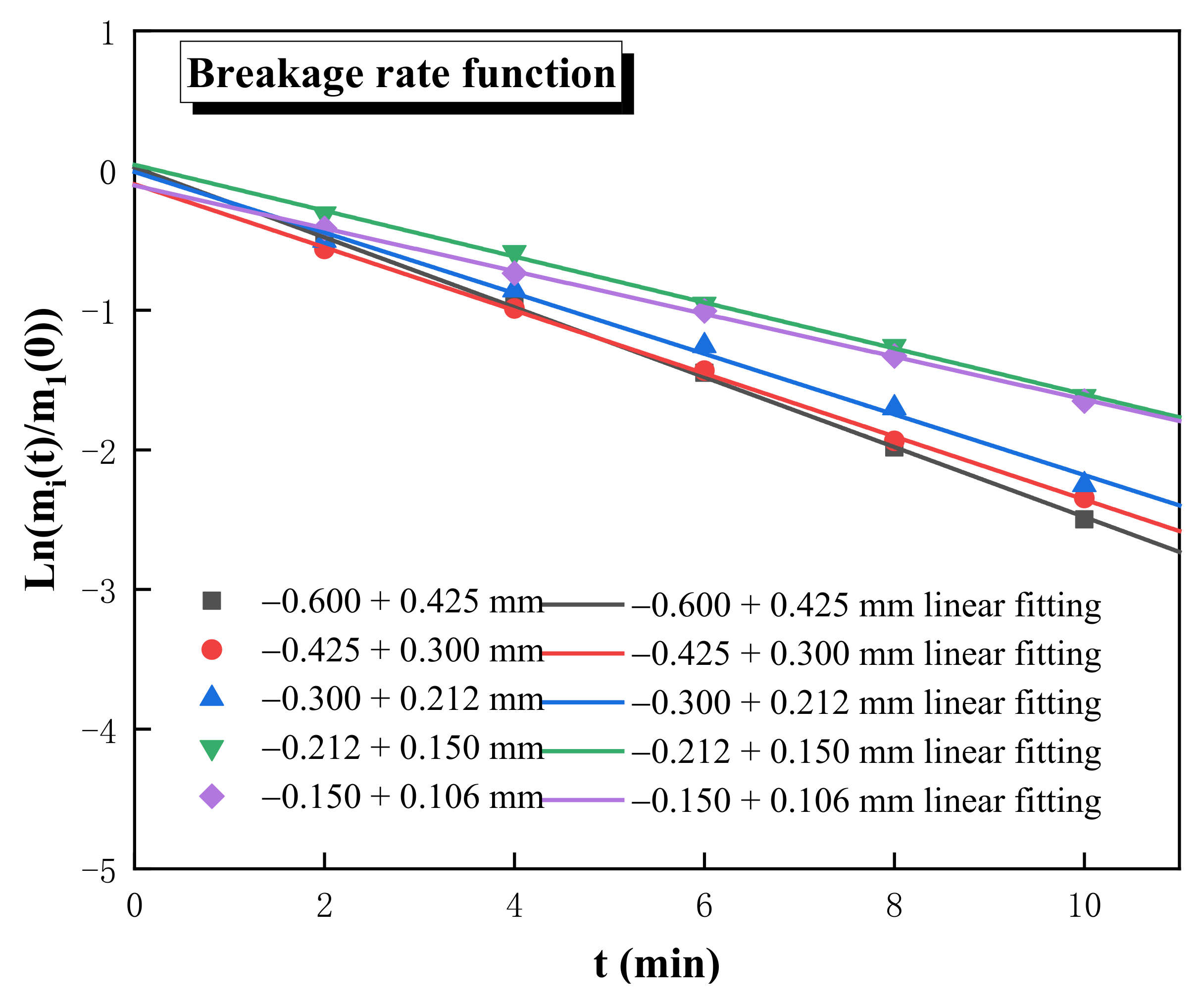
The test results obtained from Equation (6) are shown in Figure 3. In the range of the feed fractions, magnetite met the first-order linear grinding kinetics, and the slope of the straight line was the breakage rate function of magnetite in this feed fraction. Table 3 shows the linear fitting equation for each fraction and its linear correlation. As can be seen, the value of the breakage rate function dropped from 0.25 min−1 to 0.15 min−1 as the particle size decreased. The reason for this phenomenon is that the compressive strength of mineral particles increased as the particle size decreased, which directly caused difficulty in grinding the mineral, also known as the size effect of the particle. Theoretically, the fitted curves of each fraction should pass through the origin of the coordinate axes; however, the fitted curves of the five feed fractions in this test all had vertical intercepts, and the sieving error was the main reason for this problem. Nevertheless, this can be introduced into the breakage parameter correction and has no influence on the calculation of the breakage rate function.
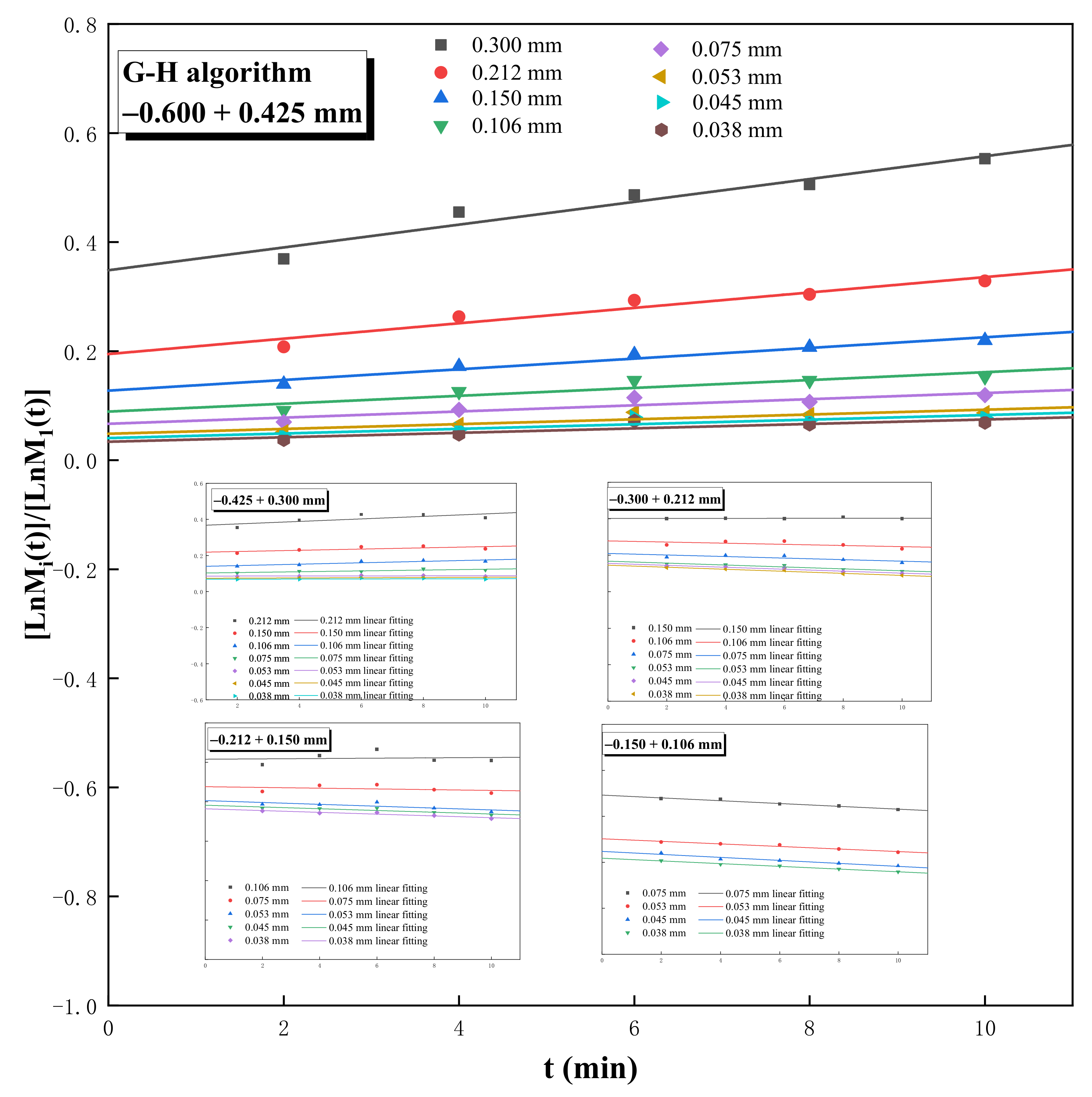
In this study, the G–H and BⅡ algorithms were used to calculate the values of the cumulative breakage distribution function Bi1. When the grinding kinetic model is a first-order linear type, in the G–H algorithm, [lnMi(t)]/[lnM1(t)] is a function of grinding time t, and Bi1 is the vertical coordinate intercept when t = 0.
Figure 4 shows the result of the G–H algorithm. For a feed fraction of −0.600 + 0.425 mm, the value of Bi1 was between 0 and 0.4, and the smaller the particle size, the finer the value of Bi1 was. Furthermore, because the breakage characteristic was abrasion, it was outstandingly characterized by a low yield of intermediate daughter fractions, resulting in a more convergent value of Bi1 within a certain particle size range. Generally, as the feed fraction becomes finer, the decrease in the number of daughter fractions leads to an increase in the Bi1 value of each daughter fraction.
When using the BⅡ algorithm to calculate the cumulative breakage distribution function, a relatively short grinding time was chosen, and the appropriate grinding time was generally no more than 65% of the breakage rate of the feed fractions. When the grinding time of the magnetite ore was 2 min, only 45.75% of −0.600 + 0.425 mm magnetite was crushed, which was in line with the range of the BⅡ algorithm.
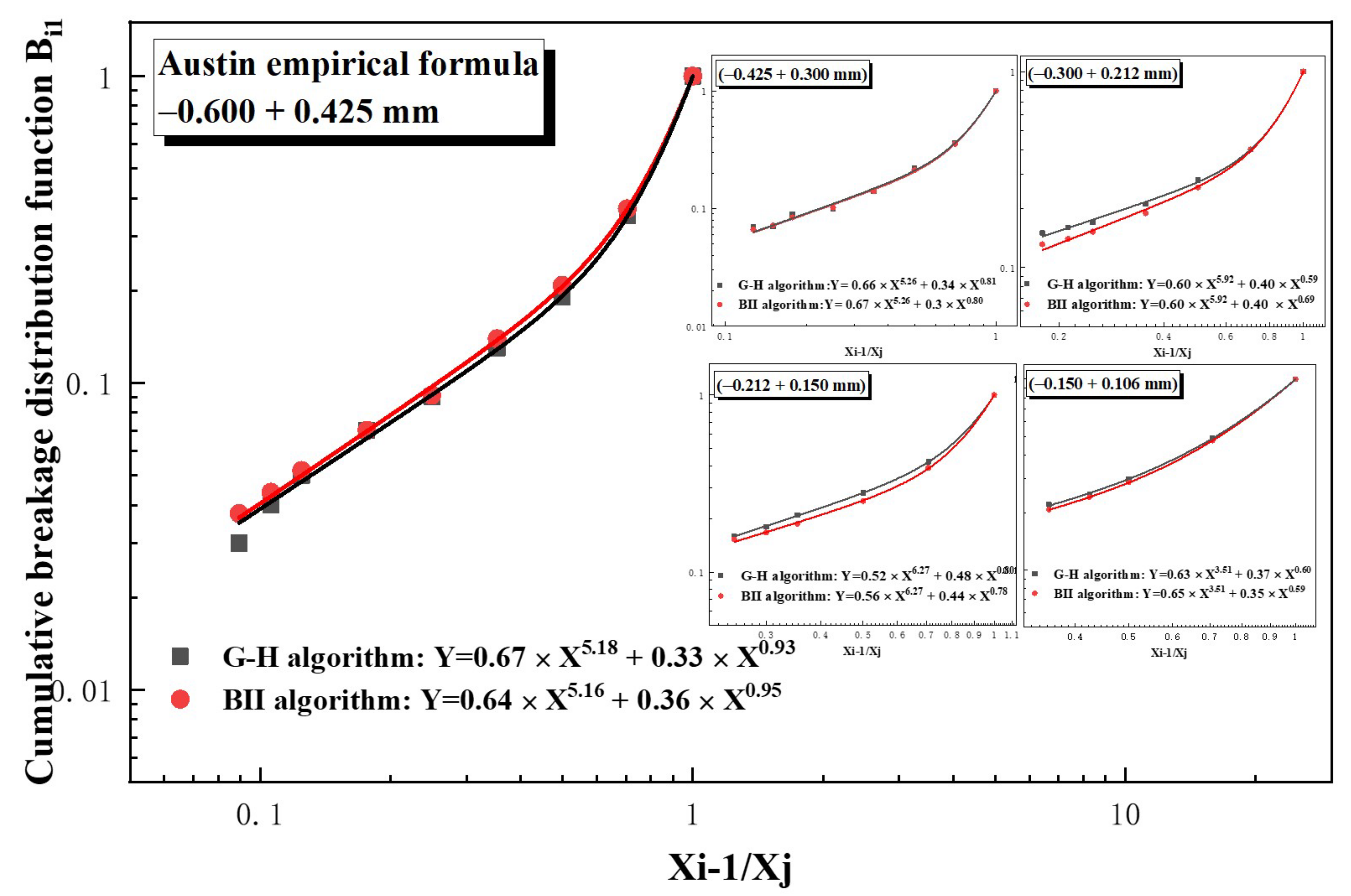
The calculation results of the two algorithms were brought into the Austin empirical formula, and the fitting results are shown in Figure 5. The curves fitted using the two methods were relatively similar, and the values of the fragmentation parameters φ, γ, and β for the magnetite produced with the fit are summarized in Table 4 for a better comparison of the two algorithms. The parameter values obtained using the two methods showed very little variation and were within the error of the calculation results. Taking the −0.600 + 0.425 mm grain size as an example, the maximum calculation error was only 0.03, and hence it can be concluded that the calculation of Bi1 was relatively accurate. However, when it came to the finest feed fraction −0.150 + 0.106 mm, the fitting results were far from the results of other coarser feed fractions. One possible reason for the difference is that fewer data points were used for fitting, resulting in larger fitting errors, and another possible reason is that it was more difficult to determine the endpoint of sieving in the finer fractions, leaving a larger experimental error. It was critical to have sufficient data points in the fit, and the number of data points should preferably be more than five.
γ is a parameter indicating the magnitude of the mechanical strength. As the feed size decreased, the γ value gradually increased, which was another manifestation of the size effect of the particles.

4.2. Method Ⅱ

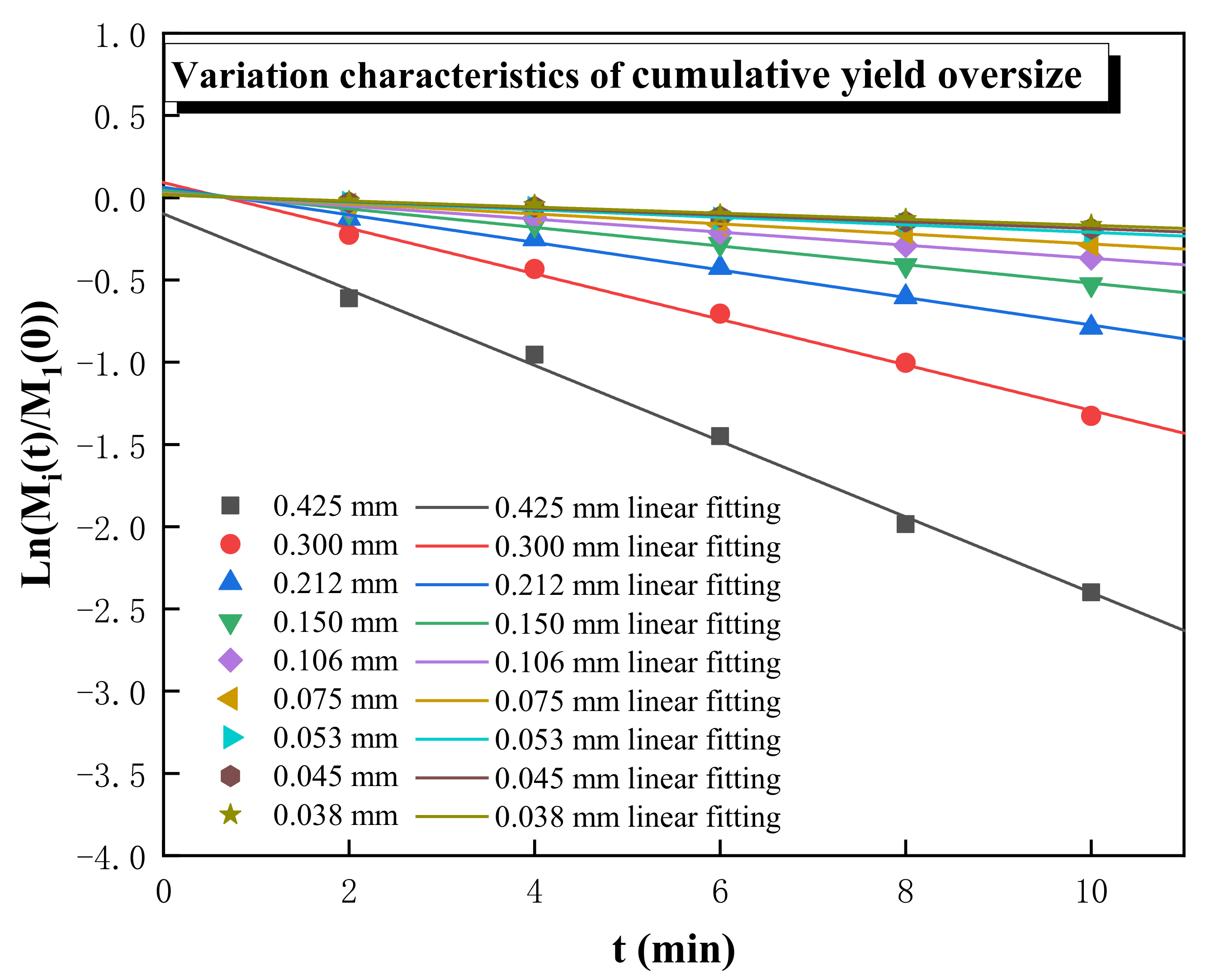
It was found that the variation in t would not affect the change rate of the cumulative mass fraction coarser than size class i at time t; Mi(t) also followed the first-order grinding kinetics. Taking −0.600 + 0.425 mm as an example, Figure 6 shows that ln[Mi(t)]/M1(0)] changed in characteristics after grinding time t, suggesting a high linear fit correlation between ln[Mi(t)]/M1(0)] and t. Additionally, the fitting equation and linear fit correlation coefficient R2 are shown in Table 5. The R2 of the last two size classes decreased because of their lower yields, the fitting results of which would be greatly affected by experimental chance errors. The g i value gradually decreased as the particle size became finer, indicating that the generation rate of the fine particle size was significantly lower than that of the coarse particle size.
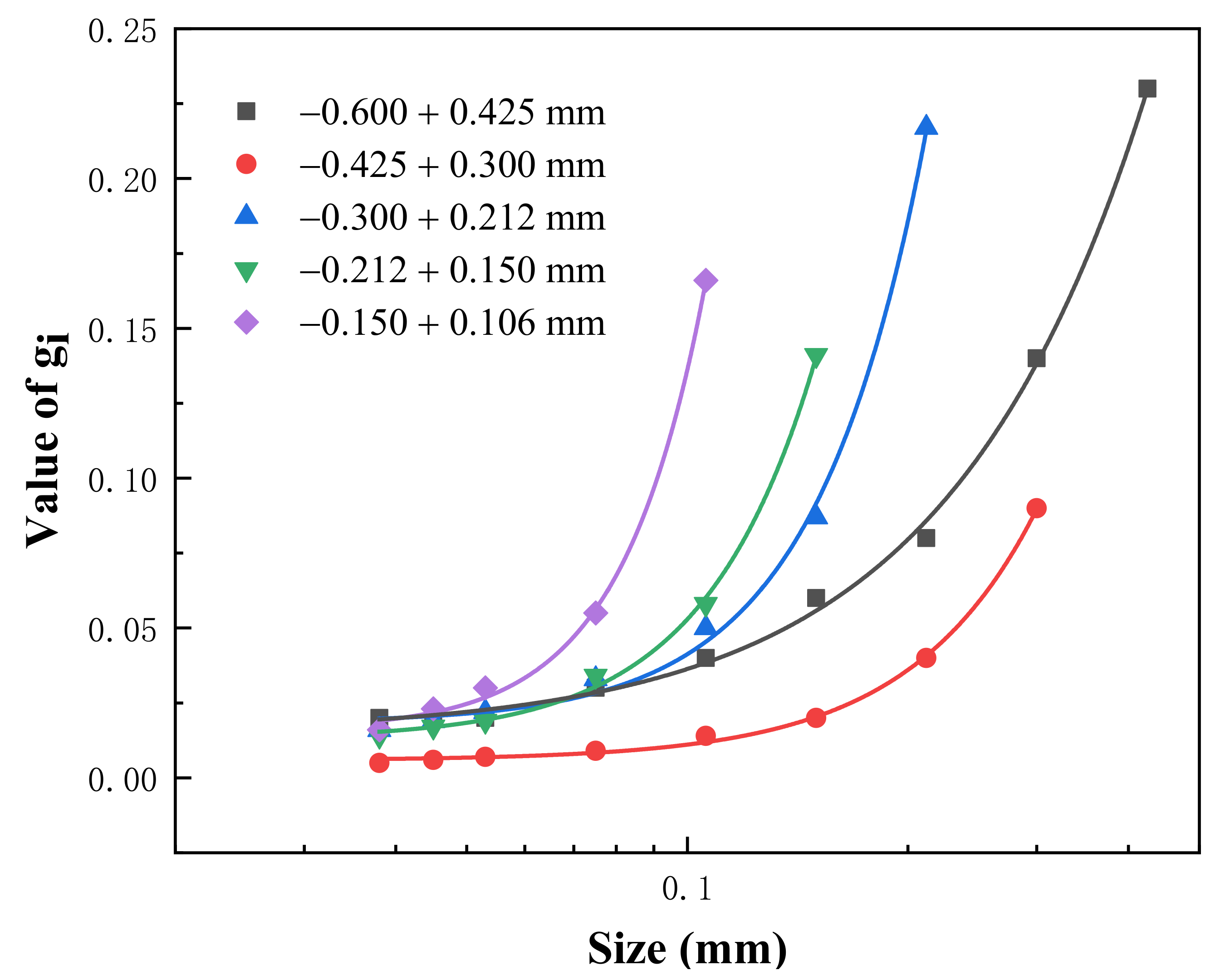
Figure 7 shows the variation in the gi value with different particle sizes. Additionally, taking the value of −0.600 + 0.425 mm as an example, the values of k0, k1, and a were 0.007, 0.786, and 1.666, respectively, by fitting the gi function, and the R2 value was 0.9978. The parameters calculated with regression were plugged into Equation (15):
g i = 0.007 + 0.786 x i 1.666
Since k0 is a parameter for the experimental chance error, when its value tends to be 0, it can be neglected, so Equation (20) can be abbreviated as follows:
g i = 0.786 x i 1.666
The final grinding kinetic model calculated using Method Ⅱ was obtained by combining Equations (18) and (21):
m i t = e 0.23 t ;   i = 1 m i t = e 0.786 x i 1.666 e 0.786 x i 1 1.666 e t ;   ( i > 1 )
The remaining four feed fractions were calculated according to the above method, and the values of the calculated parameters k1, k2, and a are shown in Table 6.

4.3. Simulation and Comparison

While processing the grinding of magnetite, the breakage rate function S1 can be determined using Equation (6), the cumulative breakage distribution function Bi1 can be generated using Equation (9), and the rate constant gi can be calculated using Equation (15). These parameters were input into Equations (10) and (18) for simulation, and the models derived from the two methods for each of the feed fractions are shown in Table 7 (when i = 1, the two methods yield the same model, so they are not listed). Because Method Ⅱ involves fewer parameters, the final model is simpler than Method Ⅰ.
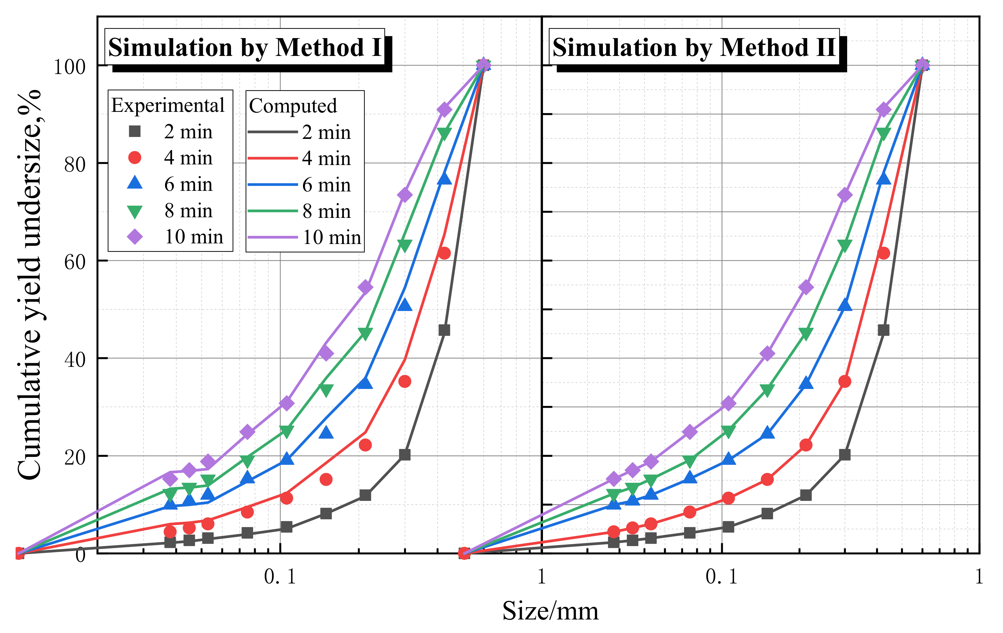
Simulation results and their fitting with the experimental data of −0.600 + 0.425 mm are shown in Figure 8. Both methods obtained satisfactory fitting results, and the experimental data overlapped well with the calculated data from simulations, suggesting that in general, both methods could be used to describe the size characteristics of the grinding product. The curve obtained using the model of Method II was smoother than the fit of Method I because Method I involved iterative fitting, and the error was significantly magnified in the process of obtaining the two fits. In addition, when the model of Method I was used to predict the cumulative yield undersize for the fine particle size (less than 40 μm), there was a large relative error in the calculation of the cumulative distribution function, resulting in a relatively large error in the final fitting results.
Table 8 demonstrates a comparison between the results of simulation calculations and the actual experiment for each fraction using the two methods after grinding for 2 min. The maximum error between the simulation calculations and the experimental results did not exceed 1%, indicating that the value of fragmentation parameters of magnetite was correct. Therefore, it can be assumed that the mathematical models derived from the two methods can make theoretical predictions and determine the particle size characteristics of narrow-size magnetite grinding products.
The comparison results for when the grinding time was 4 min are summarized in Table 9. The error of each size using Method Ⅱ was basically below 2% mass fraction, but the error of Method Ⅰ was around 3% mass fraction, especially for 0.300 mm with the error reaching 4.49% mass fraction. Overall, the fit of Method Ⅱ was significantly better than that of Method Ⅰ, and the prediction of the grinding product’s size characteristics was more accurate.
In general, compared with Method Ⅰ, this method demonstrates two merits. First, it demands less effort to calculate the value of the cumulative breakage distribution function (Bij), which greatly reduces the overall computational process and workload and thus generates higher fitting accuracy.
Second, the three parameters φ, γ, and β in Method Ⅰ had some errors in the fitting calculation, which caused a prediction bias [15]. To reduce these errors, some scholars suggested that while calculating these parameters, the value of β could be first fixed according to the results generated by peer researchers, so that the other two parameters could be calculated. However, this effect is not obvious. Therefore, there are fewer derived parameters in Method Ⅱ for batch grinding, which means the number and degree of the error for each parameter are limited, and thus there would be less negative effect on the research of grinding characteristics. Additionally, it is worth mentioning that our recent studies have confirmed that Method Ⅱ is also more accurate for the case of wide-size grinding.
Third, given the previous two advantages, this method could be applied in studying the impact of parameters, such as rotational speed, diameter, etc., on the grinding status with a simpler process and higher accuracy.
However, as a new approach to grinding kinetics, Method Ⅱ has only proven its accuracy in batch grinding so far. Extensive work is still needed to verify its applicability in continuous grinding.

5. Conclusions

Through the study of the breakage characteristics of five feed fractions taking the simulation of −0.600 + 0.425 mm as an example (−0.600 + 0.425 mm, −0.425 + 0.300 mm, −0.300 + 0.212 mm, −0.212 + 0.150 mm, and −0.150 + 0.106 mm), it was found that the cumulative mass fraction coarser than the size class of the discharge was also consistent with the first-order grinding kinetic model, and thus a new method of calculating grinding kinetics was proposed on this basis. The maximum error between simulation calculations and the actual experiment for each fraction using the two methods did not exceed 1%, indicating that the value of the fragmentation parameters of magnetite were both correct. The distribution function commonly used in the population balance model is a sum of two power functions: B i 1 = φ ( x i 1 x 1 + 1 φ ( x i 1 x 1 ) β . The g i function of the new approach is only a single power function = + k 1 x i a , which will greatly reduce the parameter error and make the fit more accurate. Compared with the analytical solution derived from the population balance model, the new approach solves the following two shortcomings of the conventional method:
1. The huge amount of computation due to the calculation of Bi1;
2. The Non-negligible fitting error due to more derived parameters.
This new method is also applicable to minerals other than magnetite. Hence, the new method could be applied in studying the impact of parameters, such as rotational speed, diameter, etc., on the grinding status with a simpler process and higher accuracy. Nevertheless, as a new approach to grinding kinetics, Method Ⅱ has only proven its accuracy in batch grinding so far. Further research is needed to verify its applicability in a wide size range and continuous grinding.

Supplementary Materials

The following supporting information can be downloaded at: https://www.mdpi.com/article/10.3390/min13030424/s1, Table S1: Grinding experiment data.

Author Contributions

Conceptualization, C.Y. and C.W.; methodology, X.F.; validation, Y.L. and X.F.; formal analysis, N.L.; investigation, C.Y.; resources, J.T.; data curation, X.F.; writing—original draft preparation, C.Y.; writing—review and editing, C.Y.; visualization, J.T.; supervision, N.L.; project administration, C.W.; funding acquisition, C.W. All authors have read and agreed to the published version of the manuscript.

Funding

This research was funded by the National Natural Science Foundation of China: 51764015.

Data Availability Statement

The raw data from the experiments are attached to the table of grinding experimental data in the Supplementary Materials.

Acknowledgments

The authors gratefully acknowledge the financial support from the National Natural Science Foundation of China (Grant No. 51764015).

Conflicts of Interest

The authors declare no conflict of interest.

References

  1. Zhao, R.; Han, Y.; He, M.; Li, Y. Grinding kinetics of quartz and chlorite in wet ball milling. Powder Technol. 2017, 305, 418–425. [Google Scholar] [CrossRef]
  2. Fuerstenau, D.W.; Phatak, P.B.; Kapur, P.C.; Abouzeid, A.Z.M. Simulation of the grinding of coarse/fine (heterogeneous) systems in a ball mill. Int. J. Miner. Process. 2011, 99, 32–38. [Google Scholar] [CrossRef]
  3. Epstein, B. Logarithmico-Normal Distribution in Breakage of Solids. Ind. Eng. Chem. 1948, 40, 2289–2291. [Google Scholar] [CrossRef]
  4. Sedlatschek, K. Contribution to the theory of milling processes. Powder Metal. Bull 1953, 6, 148–153. [Google Scholar]
  5. Broadbent, S.R. A matrix analysis of processes involving particle assemblies. Philos. Trans. R. Soc. 1956, 249, 99–123. [Google Scholar]
  6. Reid, K.J. A solution to the batch grinding equation. Chem. Eng. Sci. 1965, 20, 953–963. [Google Scholar] [CrossRef]
  7. Kapur, P.C. Appropriate solutions to the discretized batch grinding equation. Chem. Eng. Sci. 1970, 25, 1111–1113. [Google Scholar] [CrossRef]
  8. Austin, L.G. Methods for Determination of Breakage Distribution Parameters. Powder Technol. 1971, 72, 215–222. [Google Scholar] [CrossRef]
  9. Venkataraman, K.S. Application of the Population Balance Model to the Grinding of Mixtures of Minerals. Powder Technol. 1984, 39, 133–142. [Google Scholar] [CrossRef]
  10. Austin, L.G. A discussion of equations for the analysis of batch grinding data. Powder Technol. 1999, 106, 71–77. [Google Scholar] [CrossRef]
  11. Bilgili, E.; Scarlett, B. Population balance modeling of non-linear effects in milling processes. Powder Technol. 2005, 153, 59–71. [Google Scholar] [CrossRef]
  12. Kapur, P.C. Energy Split in Multicomponent Grinding. Int. J. Miner. Process. 1988, 24, 125–142. [Google Scholar] [CrossRef]
  13. Li, P.; Cao, Z.; Zhao, R.; Li, G.; Yu, M.; Zhang, S. The kinetics and efficiency of batch ball grinding with cemented tungsten carbide balls. Adv. Powder Technol. 2020, 31, 2412–2420. [Google Scholar] [CrossRef]
  14. Qian, H.Y.; Kong, Q.G.; Zhang, B.L. The effects of grinding media shapes on the grinding kinetics of cement clinker in ball mill. Powder Technol. 2013, 235, 422–425. [Google Scholar] [CrossRef]
  15. Shahcheraghi, S.H.; Mulenga, F.K.; Tavakoli Mohammadi, M.R.; Mousavi, S.M. How precise are ore breakage parameters measured from direct batch milling tests? Miner. Eng. 2019, 137, 157–159. [Google Scholar] [CrossRef]
  16. Shahbazi, B.; Jafari, M.; Parian, M.; Rosenkranz, J.; Chehreh Chelgani, S. Study on the impacts of media shapes on the performance of tumbling mills—A review. Miner. Eng. 2020, 157, 106490. [Google Scholar] [CrossRef]
  17. Danha, G.; Hildebrandt, D.; Glasser, D.; Bhondayi, C. Application of basic process modeling in investigating the breakage behavior of UG2 ore in wet milling. Powder Technol. 2015, 279, 42–48. [Google Scholar] [CrossRef]
  18. Guo, W.; Han, Y.; Gao, P.; Li, Y.; Tang, Z. A study of the grinding of magnetite/limestone mixture in a stirred mill by the attainable region method. Powder Technol. 2021, 389, 40–47. [Google Scholar] [CrossRef]
  19. Faria, P.M.C.; Rajamani, R.K.; Tavares, L.M. Optimization of Solids Concentration in Iron Ore Ball Milling through Modeling and Simulation. Minerals 2019, 9, 366. [Google Scholar] [CrossRef] [Green Version]
  20. Ipek, H.; Ucbas, Y.; Hosten, C. Ternary-mixture grinding of ceramic raw materials. Miner. Eng. 2005, 18, 45–49. [Google Scholar] [CrossRef]
  21. Nöske, M.; Li, K.; Brüning, K.; Breitung-Faes, S.; Kwade, A. Impact of stress conditions on stirred media milling of a two component mixture. Miner. Eng. 2020, 146, 106100. [Google Scholar] [CrossRef]
  22. Xie, W.; He, Y.; Ge, Z.; Shi, F.; Yang, Y.; Li, H.; Wang, S.; Li, K. An analysis of the energy split for grinding coal/calcite mixture in a ball-and-race mill. Miner. Eng. 2016, 93, 1–9. [Google Scholar] [CrossRef]
  23. Altun, O.; Altun, D. Estimation of mineral liberation distribution functions to be used in modelling of impact and attrition milling. Miner. Eng. 2021, 173, 107236. [Google Scholar] [CrossRef]
  24. Gupta, V.K. Effect of particulate environment on the grinding kinetics of mixtures of minerals in ball mills. Powder Technol. 2020, 375, 549–558. [Google Scholar] [CrossRef]
  25. Gupta, V.K. Energy absorption and specific breakage rate of particles under different operating conditions in dry ball milling. Powder Technol. 2020, 361, 827–835. [Google Scholar] [CrossRef]
  26. Gupta, V.K. Population balance modeling approach to determining the mill diameter scale-up factor: Consideration of size distributions of the ball and particulate contents of the mill. Powder Technol. 2022, 395, 412–423. [Google Scholar] [CrossRef]
  27. Mulenga, F.K.; Gharehgheshlagh, H.H.; Chehreghani, S. Assessing the dependency of selection function parameters with batch mill design. Adv. Powder Technol. 2019, 30, 2042–2051. [Google Scholar] [CrossRef]
  28. Gao, P.; Zhou, W.; Han, Y.; Li, Y.; Ren, W. Enhancing the capacity of large-scale ball mill through process and equipment optimization: An industrial test verification. Adv. Powder Technol. 2020, 31, 2079–2091. [Google Scholar] [CrossRef]
  29. Farber, B.Y.; Durant, B.; Bedesi, N. Effect of media size and mechanical properties on milling efficiency and media consumption. Miner. Eng. 2011, 24, 367–372. [Google Scholar] [CrossRef]
  30. Hanumanthappa, H.; Vardhan, H.; Mandela, G.R.; Kaza, M.; Sah, R.; Shanmugam, B.K. A comparative study on a newly designed ball mill and the conventional ball mill performance with respect to the particle size distribution and recirculating load at the discharge end. Miner. Eng. 2020, 145, 106091. [Google Scholar] [CrossRef]
  31. Jayasundara, C.T.; Yang, R.Y.; Yu, A.B. Effect of the size of media on grinding performance in stirred mills. Miner. Eng. 2012, 33, 66–71. [Google Scholar] [CrossRef]
  32. Larsson, S.; Pålsson, B.I.; Parian, M.; Jonsén, P. A novel approach for modelling of physical interactions between slurry, grinding media and mill structure in wet stirred media mills. Miner. Eng. 2020, 148, 106180. [Google Scholar] [CrossRef]
  33. Altun, O.; Prziwara, P.; Breitung-Faes, S.; Kwade, A. Impacts of process and design conditions of dry stirred milling on the shape of product size distribution. Miner. Eng. 2021, 163, 106806. [Google Scholar] [CrossRef]
  34. Altun, O.; Darılmaz, Ö.; Karahan, E.; Sert, T.; Altun, D.; Toprak, A.; Hür, A. Understanding HIGMill operation at copper regrind application; operating parameters, wear and mineral liberation. Miner. Eng. 2023, 191, 107964. [Google Scholar] [CrossRef]
  35. Austin, L.G. Note on influence of interval size on the first-order hypothesis of grinding. Powder Technol. 1971, 71, 109–110. [Google Scholar] [CrossRef]
  36. Chimwani, N.; Glasser, D.; Hildebrandt, D.; Metzger, M.J.; Mulenga, F.K. Determination of the milling parameters of a platinum group minerals ore to optimize product size distribution for flotation purposes. Miner. Eng. 2013, 43, 67–78. [Google Scholar] [CrossRef]
  37. Gupta, V.K.; Sharma, S. Analysis of ball mill grinding operation using mill power specific kinetic parameters. Adv. Powder Technol. 2014, 25, 625–634. [Google Scholar] [CrossRef]
  38. Bond, F.C. Crushing-and-Grinding-Calculations.pdf. Addit. Revis. 1961, 6, 543–548. [Google Scholar]
Figure 2. The logic diagram of the population balance model for narrow-size minerals.
Minerals 13 00424 g002
Figure 3. Breakage behavior of magnetite for various feed fractions.
Minerals 13 00424 g003
Figure 4. G–H algorithm plot for magnetite wet-grinding experiment.
Minerals 13 00424 g004
Figure 5. Austin empirical formula for magnetite wet-grinding experiment.
Minerals 13 00424 g005
Figure 6. Variation characteristics of cumulative yield oversize in discharge.
Minerals 13 00424 g006
Figure 7. Variation characteristics of gi in daughter fractions.
Minerals 13 00424 g007
Figure 8. Simulations using the two methods in the grinding of −0.600 + 0.425 mm magnetite.
Minerals 13 00424 g008
Table 1. Particle size range of the grinding products.
FractionsSize Class (mm)
Fraction 1−0.600 + 0.425
Fraction 2−0.425 + 0.300
Fraction 3−0.300 + 0.212
Fraction 4−0.212 + 0.150
Fraction 5−0.150 + 0.106
Fraction 6−0.106 + 0.075
Fraction 7−0.075 + 0.053
Fraction 8−0.053 + 0.045
Fraction 9−0.045 + 0.038
Table 2. The operating conditions of the grinding products.
ConditionsValue
Media Steel ball
Weight of the media (g)1940
Size of the media (mm)25
Bulk density of the media (t/m3)4.85
Filling rate of the media (%)20
Slurry concentration by mass (%)67
Cylinder diameter (cm)15
Speed (r/min)85
Volume (L)2
Table 3. The operating conditions of the discharge.
Feed Fractions (mm)Fitting Equation Adj.R2
−0.600 + 0.425Y = −0.25t − 0.020.9954
−0.425 + 0.300Y = −0.23t − 0.090.9771
−0.300 + 0.212Y = − 0.22t − 0.010.9927
−0.212 + 0.150Y = − 0.16t − 0.040.9920
−0.150 + 0.106Y = − 0.15t − 0.090.9915
Note: Y = Ln[mi(t)/m1(0)].
Table 4. Breakage distribution function parameters for magnetite.
Feed Fractions (mm)Algorithm φγβ
−0.600 + 0.425G–H algorithm 0.675.180.93
BⅡ algorithm 0.645.160.95
−0.425 + 0.300G–H algorithm 0.665.260.81
BⅡ algorithm 0.675.260.80
−0.300 + 0.212G–H algorithm 0.605.920.59
BⅡ algorithm 0.605.920.69
−0.212 + 0.150G–H algorithm 0.526.270.80
BⅡ algorithm 0.566.270.78
−0.150 + 0.106G–H algorithm 0.633.510.60
BⅡ algorithm 0.653.510.59
Table 5. The fitting equation and linear fit correlation coefficient R2 of ln[Mi(t)]/M1(0)] − t.
Size Classes (mm)Fitting Equation R2
−0.600 + 0.425Y = −0.23t − 0.090.9982
−0.425 + 0.300Y = −0.14t + 0.090.9955
−0.300 + 0.212Y = −0.08t + 0.060.9950
−0.212 + 0.150Y = −0.06t + 0.050.9940
−0.150 + 0.106Y = −0.04t + 0.030.9960
−0.106 + 0.075Y = −0.03t + 0.020.9940
−0.075 + 0.053Y = −0.02t + 0.020.9931
−0.053 + 0.045Y = −0.02t + 0.020.9914
−0.045 + 0.038Y = −0.02t + 0.020.9884
Note: Y = Ln[Mi(t)/M1(0)].
Table 6. Values of each parameter for different feed fractions.
Feed Fractions (mm)K1 K2a
−0.600 + 0.4250.0070.7861.666
−0.425 + 0.3000.0051.7562.525
−0.300 + 0.2120.0102.4091.819
−0.212 + 0.1500.0063.4561.870
−0.150 + 0.1060.0533.0481.515
Table 7. The model derived from the two methods for each of the feed fractions (i > 1).
Feed Fractions (mm)Method Model
−0.600 + 0.425 m i t = e 0.25 [ 0.67 ( x i 1 x 1 ) 5.18 + 0.33 ( x i 1 x 1 ) 0.93 ] t
m i t = e 0.786 x i 1.666 e 0.786 x i 1 1.666 e t
−0.425 + 0.300 m i t = e 0.23 [ 0.66 ( x i 1 x 1 ) 5.26 + 0.34 ( x i 1 x 1 ) 0.81 ] t
m i t = e 1.756 x i 2.525 e 1.756 x i 1 2.525 e t
−0.300 + 0.212 m i t = e 0.22 [ 0.60 ( x i 1 x 1 ) 5.92 + 0.40 ( x i 1 x 1 ) 0.59 ] t
m i t = e 2.409 x i 1.819 e 2.409 x i 1 1.819 e t
−0.212 + 0.150 m i t = e 0.16 [ 0.52 ( x i 1 x 1 ) 6.27 + 0.48 ( x i 1 x 1 ) 0.80 ] t
m i t = e 3.456 x i 1.870 e 3.456 x i 1 1.870 e t
−0.150 + 0.106 m i t = e 0.15 [ 0.63 ( x i 1 x 1 ) 3.51 + 0.37 ( x i 1 x 1 ) 0.60 ] t
m i t = e 3.048 x i 1.515 e 3.048 x i 1 1.515 e t
Table 8. The comparison of the simulation by two methods (grinding for 2 min).
Size/mmExperimentalMethod ⅠMethod ⅡError ⅠError Ⅱ
0.42545.7545.1245.12−0.63 −0.63
0.30020.2120.2320.190.02 −0.02
0.21211.9411.7512.42−0.19 0.48
0.1508.178.157.75−0.02 −0.42
0.1065.425.075.01−0.35 −0.41
0.0754.193.923.44−0.27 −0.75
0.0533.122.962.54−0.16 −0.57
0.0452.662.472.27−0.19 −0.39
0.0382.272.182.06−0.09 −0.21
Standard error---
Table 9. The comparison of the simulation using the two methods (grinding for 4 min).
Size/mmExperimentalMethod ⅠMethod ⅡError ⅠError Ⅱ
0.42561.5065.3560.013.86 −1.49
0.30035.2239.7136.304.49 1.08
0.21222.2024.8023.302.60 1.09
0.15015.1318.5414.903.40 −0.24
0.10611.3312.379.771.04 −1.56
0.0758.469.526.761.06 −1.69
0.0536.036.765.030.73 −1.01
0.0455.236.294.491.07 −0.74
0.0384.426.014.071.59 −0.35
Disclaimer/Publisher’s Note: The statements, opinions and data contained in all publications are solely those of the individual author(s) and contributor(s) and not of MDPI and/or the editor(s). MDPI and/or the editor(s) disclaim responsibility for any injury to people or property resulting from any ideas, methods, instructions or products referred to in the content.

