Article

Study on Stability Control Mechanism of Deep Soft Rock Roadway and Active Support Technology of Bolt-Grouting Flexible Bolt

1
State Key Laboratory of Deep Coal Mine Mining Response and Disaster Prevention and Control, Anhui University of Science and Technology, Huainan 232001, China
2
School of Mining Engineering, Anhui University of Science and Technology, Huainan 232001, China
3
Suzhou Qinan Industry and Trade Co., Ltd., Suzhou 234000, China
*
Author to whom correspondence should be addressed.
Minerals 2023, 13(3), 409; https://doi.org/10.3390/min13030409
Submission received: 16 February 2023 / Revised: 3 March 2023 / Accepted: 7 March 2023 / Published: 15 March 2023
(This article belongs to the Topic Failure Characteristics of Deep Rocks, Volume II)

Abstract

:
In order to study the stability control mechanism of deep soft rock roadway and the active support technology of the anchor-grouting flexible bolt, this paper takes the west wing transportation roadway of Yuandian No. 2 Coal Mine of Huaibei Mining Co., Ltd., Huaibei, China as the research background. By analyzing the occurrence conditions and failure characteristics of the surrounding rock of the west wing transportation roadway and the structural characteristics and mechanical properties of the anchor-grouting flexible bolt, combined with the elastic–plastic and superimposed arch theory analysis, the superposition community theoretical model and the superposition joint support scheme of “bolt (cable) + anchor net + anchor-grouting flexible bolt + shotcrete support” are proposed. The reliability of the combined support scheme is analyzed by FLAC 3D numerical simulation software and field experiment. The results show that the maximum roof-to-floor convergence and two-side convergence of the west wing transportation roadway are only 30.7 mm and 27.1 mm after adopting the combined support scheme, and the deep displacement variation is within 7 mm, which can effectively maintain the stability of the roadway. The combined support scheme has a certain reference value for other similar roadways.

1. Introduction

With the progress of our society and the development of the economy, the demand for coal is also increasing every day [1,2]. In order to improve coal production better and faster, the mining depth of China′s mines has continued to extend downward since the 1980s. The average depth of vertical shafts has reached 600 m. At present, it is developing to the deep at an average speed of 10–20 m/year. The mining depth is getting deeper and deeper, and the difficulty of mining is also increasing [3,4]. At present, there is little coal left in the shallow part of the Huaibei mining area, and the buried depth of the new roadway is increasing [5,6]. With the increase in the buried depth of the new roadway, the geological conditions become complicated and diverse, especially the soft rock roadway. The traditional bolt support has been unable to effectively control the deformation of the roadway, and the safety is poor, which can not meet the design requirements and bring great safety hazards to coal mine production [7,8].
In order to solve the support problem of deep soft rock roadway, domestic and foreign scholars have performed a lot of research on its support theory and method [9,10]. Additionally, the combined support system is proposed to reinforce the surrounding rock of the roadway [11,12]. Guo et al. [13] studied the coupling support technology of soft rock roadway in Hecaogou No. 2 Mine, Yan’an, China. Wang et al. [14] studied the high-strength prestressed coupling support technology in deep, extremely soft areas. Zhang et al. [15] used the orthogonal numerical experiment of FLAC 3D to study the influence of the change in bolt parameters and plastic yield zone on the deformation of the roadway′s surrounding rock, which provided a basis for optimizing the support design of coal mine roadways. Wu et al. [16] proposed the support concept of “high pre-stress asymmetry” and the combined support method of the bolt, wire mesh and anchor cable, and verified the rationality of the support scheme through numerical simulation. Wang et al. [17] studied the failure mechanism of soft rock and roadways in deep coal mines. Feng et al. [18] analyzed the factors affecting the deformation and failure mechanism of deep roadways based on the space–time deformation distribution of 2233 working faces in the Fuxin Hengda Coal Mine, Fuxin, China. Zhang et al. [19] analyzed the energy evolution law of the surrounding rock of roadways under different roof strengths. Qin et al. [20] proposed a reinforcement scheme for deep dynamic soft rock roadway and applied it. Skrzypkowski et al. [21] used RS3 numerical software based on finite element method to establish a rock mass model with faults. Zhu et al. [22] used the numerical simulation method to study the influence of original geological conditions, strengthening the elastic modulus of the floor, strengthening the strength of side wall rock, and increasing the thickness of floor rock on the displacement of the roadway floor.
This paper takes the west wing transportation roadway of Yuandian No. 2 Coal Mine of Huaibei Mining Co., Ltd. as the research background. Based on the analysis of the occurrence conditions and deformation characteristics of the surrounding rock of the west wing transportation roadway, the structure and mechanical properties of the anchor-grouting flexible bolt and the difficulty of the original support scheme to maintain the stability of the current excavation roadway [23,24], put forward the superposition combined support scheme of “bolt (cable) + anchor net + anchor-grouting flexible bolt + shotcrete support”. Additionally, the reliability of the combined support scheme is analyzed by FLAC 3D numerical simulation software and a field experiment. The combined support scheme has a certain reference value for other similar roadways.

2. Deformation Mechanism of Surrounding Rock in Deep Soft Rock Roadway
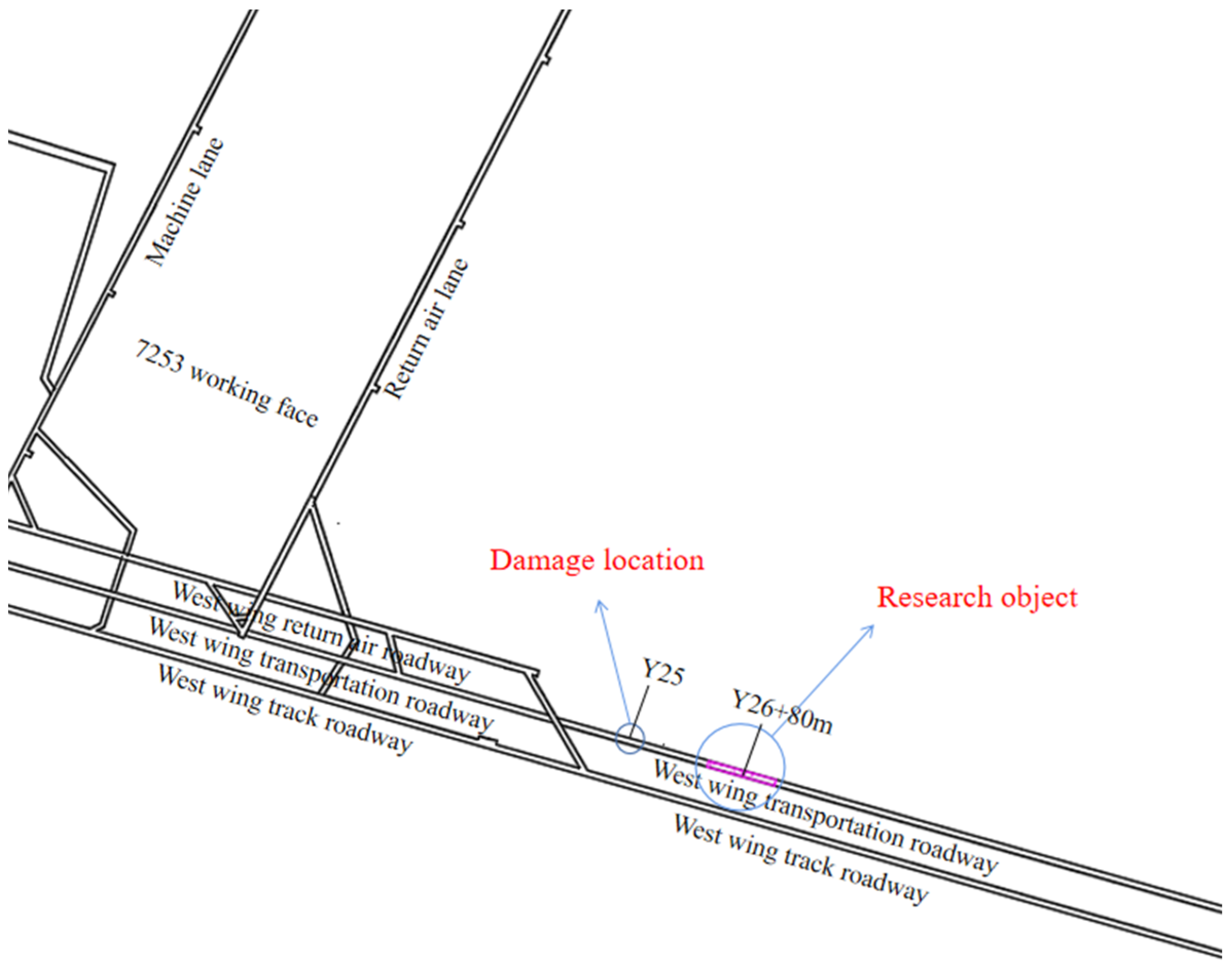
2.1. Background

The west wing transportation roadway of Yuandian No.2 Coal Mine belongs to Yuandian No.2 Coal Mine of Bozhou Coal Industry Co., Ltd. in the Huaibei Mining Area of Anhui Province. The geographical location of Yuandian No.2 Mine is shown in Figure 1. The location of the west wing transport lane is shown in Figure 2.
The elevation of the west wing transport roadway is −745~−740.7 m, the south is adjacent to the west wing return air roadway, the north is close to the west wing track roadway, and the west is to the JF245 fault, with an average dip angle of 20°. The construction horizon of the west wing transportation roadway is located in the roof of the No.6 coal seam. The lithology is mainly mudstone, siltstone and sandstone. The comprehensive state diagram of the surrounding rock column of the roadway is shown in Figure 3.

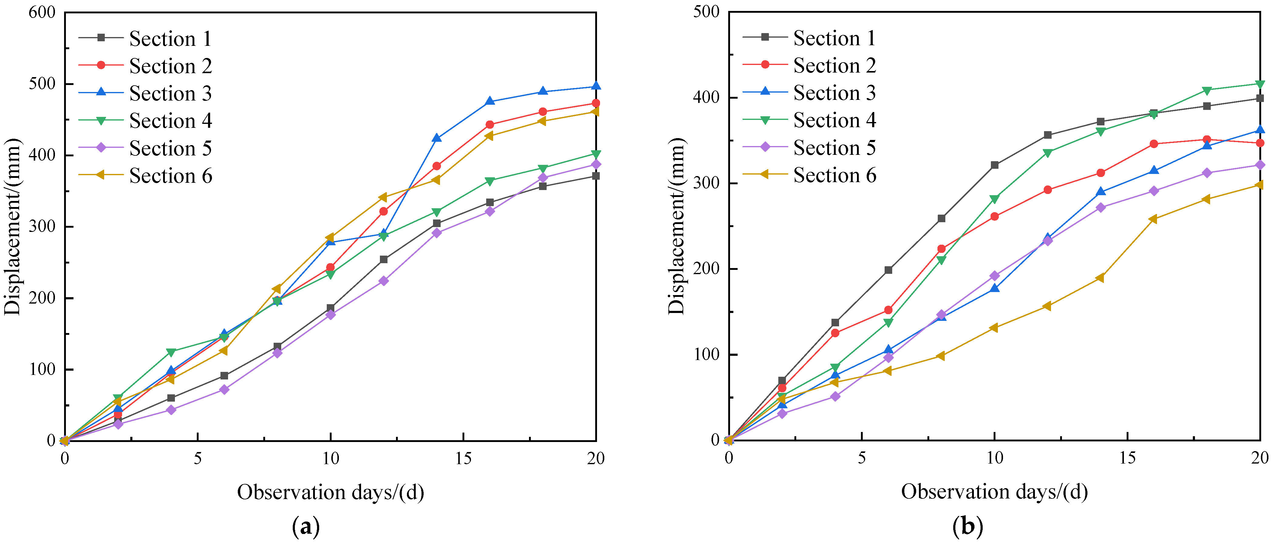
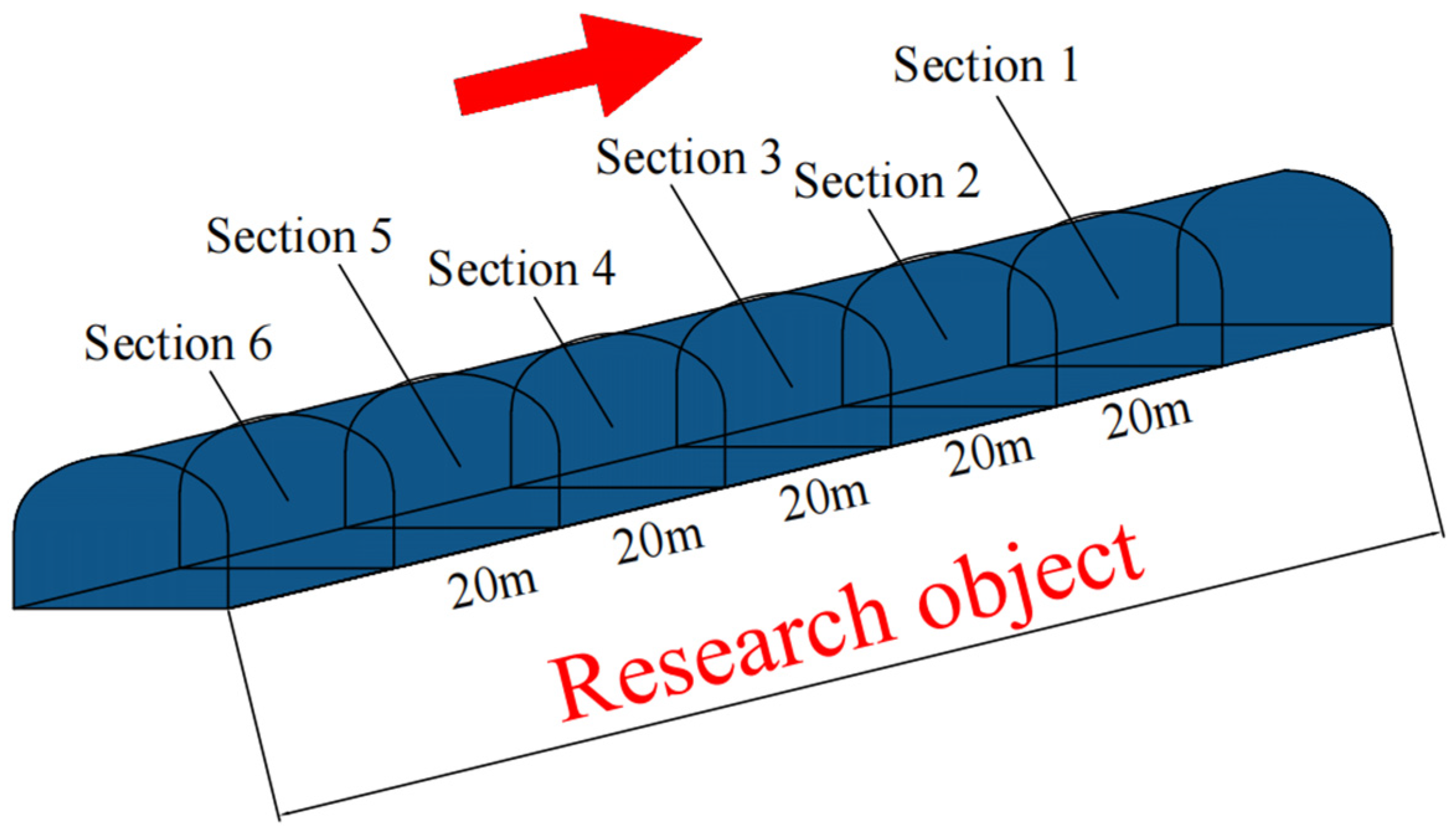
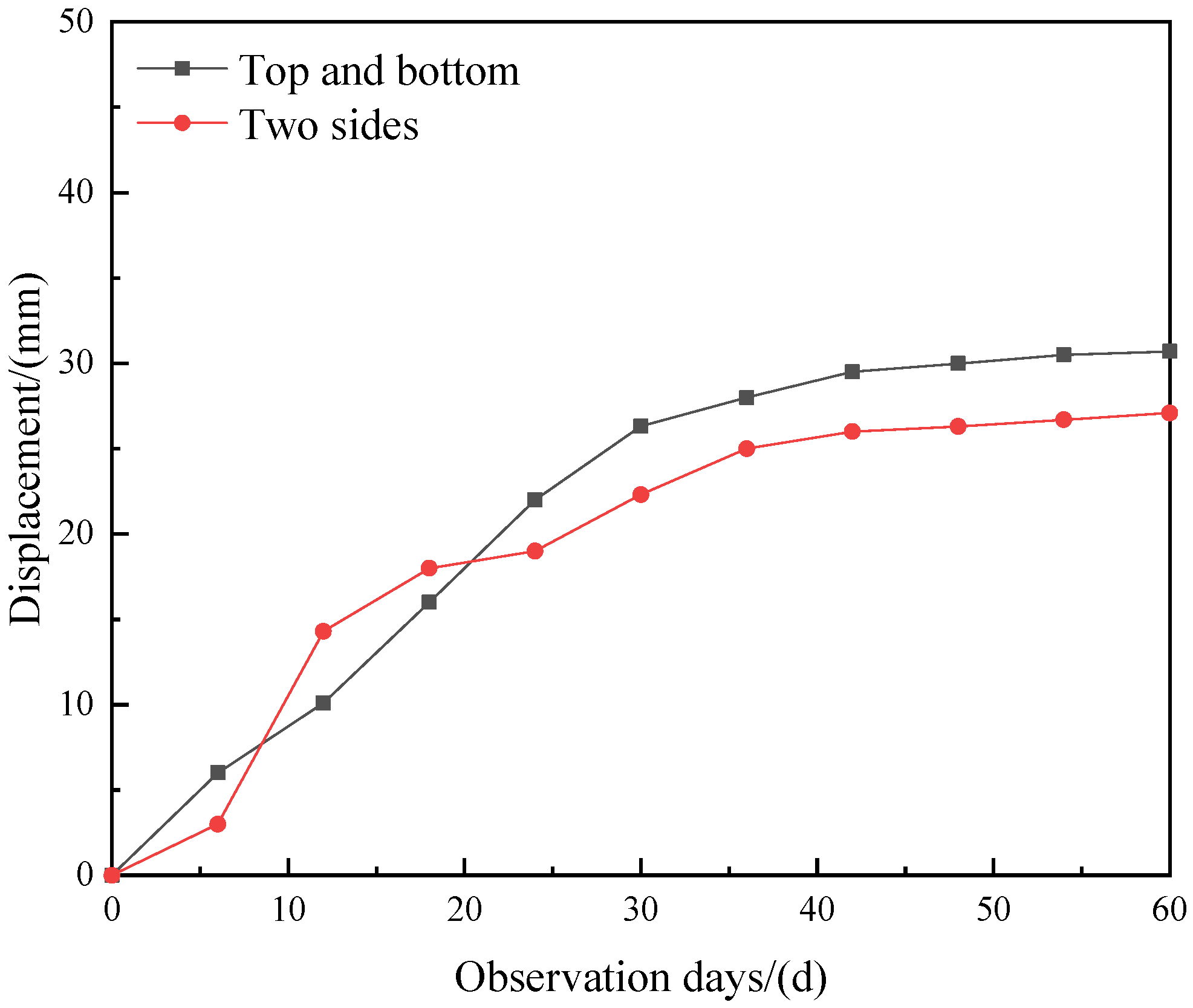
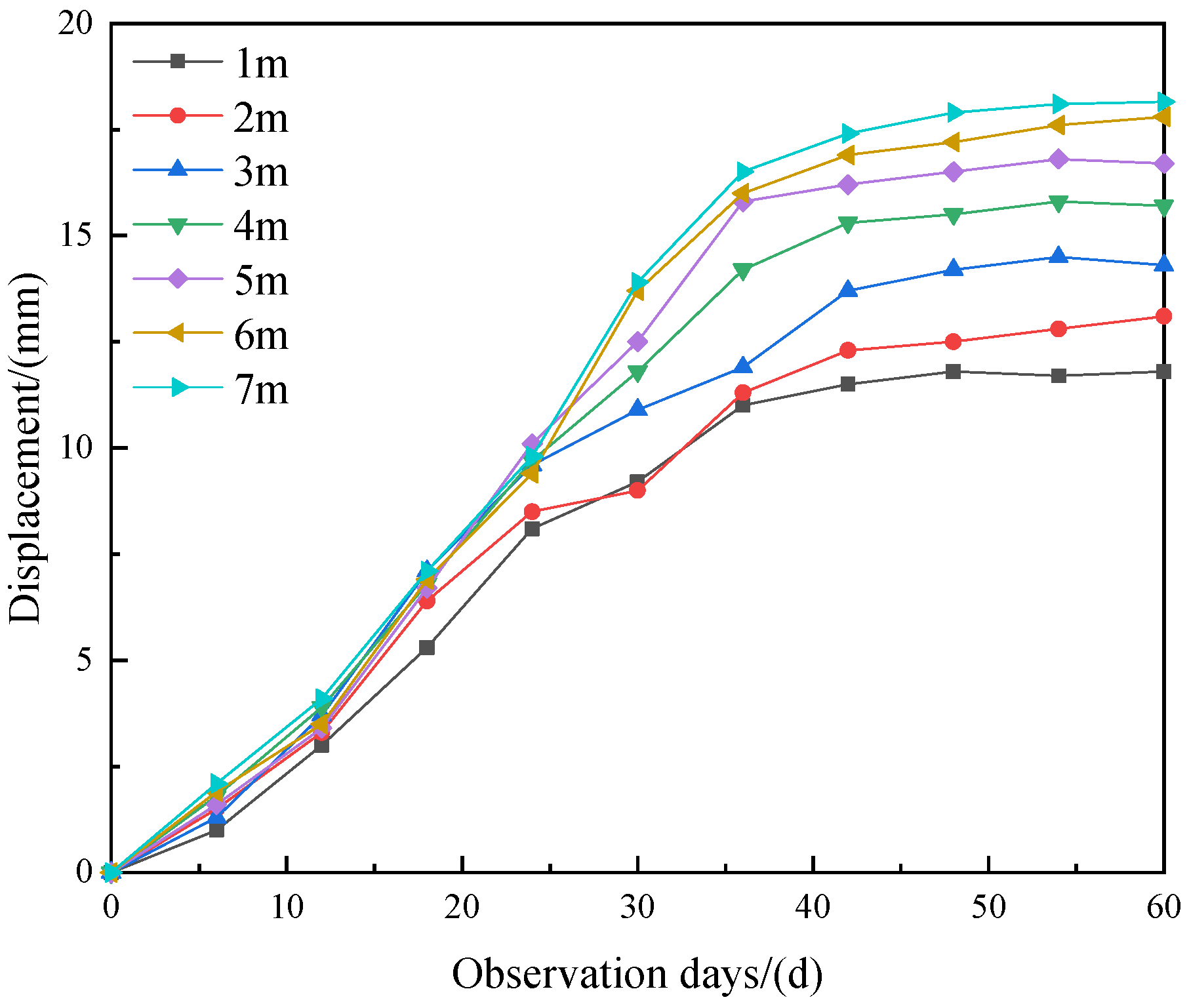
2.2. Deformation Monitoring and Analysis of West Wing Transport Roadway

The roadway section of the west wing transportation roadway is a three-center arch, and the section size is 5.0 m × 3.6 m. The original support scheme is the ordinary anchor net spray support combined with an anchor bolt, anchor cable, anchor net and shotcrete. The support is supported by a Φ22 mm × 2800 mm rebar bolt. The row spacing is 500 mm × 800 mm. The two sides and the roof are driven into the Φ22 mm × 6200 mm anchor cable, and the row spacing is 1600 mm × 1600 mm. The 100 mm × 100 mm steel bar is used to weld the warp and weft net, and the concrete with the strength grade of C20 is used to seal the surrounding rock of the roadway. Under the original support condition, the roof and side of the roadway are seriously broken, the convergence of the two sides is large and the roof subsidence is serious, which seriously affects the stability of the roadway; the failure characteristics of the roadway are shown in Figure 4. Six surface displacement observation stations were selected in the original support scheme of the west wing transport roadway. Each observation station was 20 m apart. The observation station was located at Y25 and 305 m away from the return airway of 7253 working face. The observation results are shown in Figure 5: the maximum roof and floor convergence of the west wing transport roadway is 496.5 mm, and the maximum two sides convergence is 416.5 mm. The displacement of the roof, floor and two sides is very large, and has exceeded the current maximum displacement deformation of the west wing transportation roadway. Reasonable support measures need to be taken to maintain the stability of the roadway.

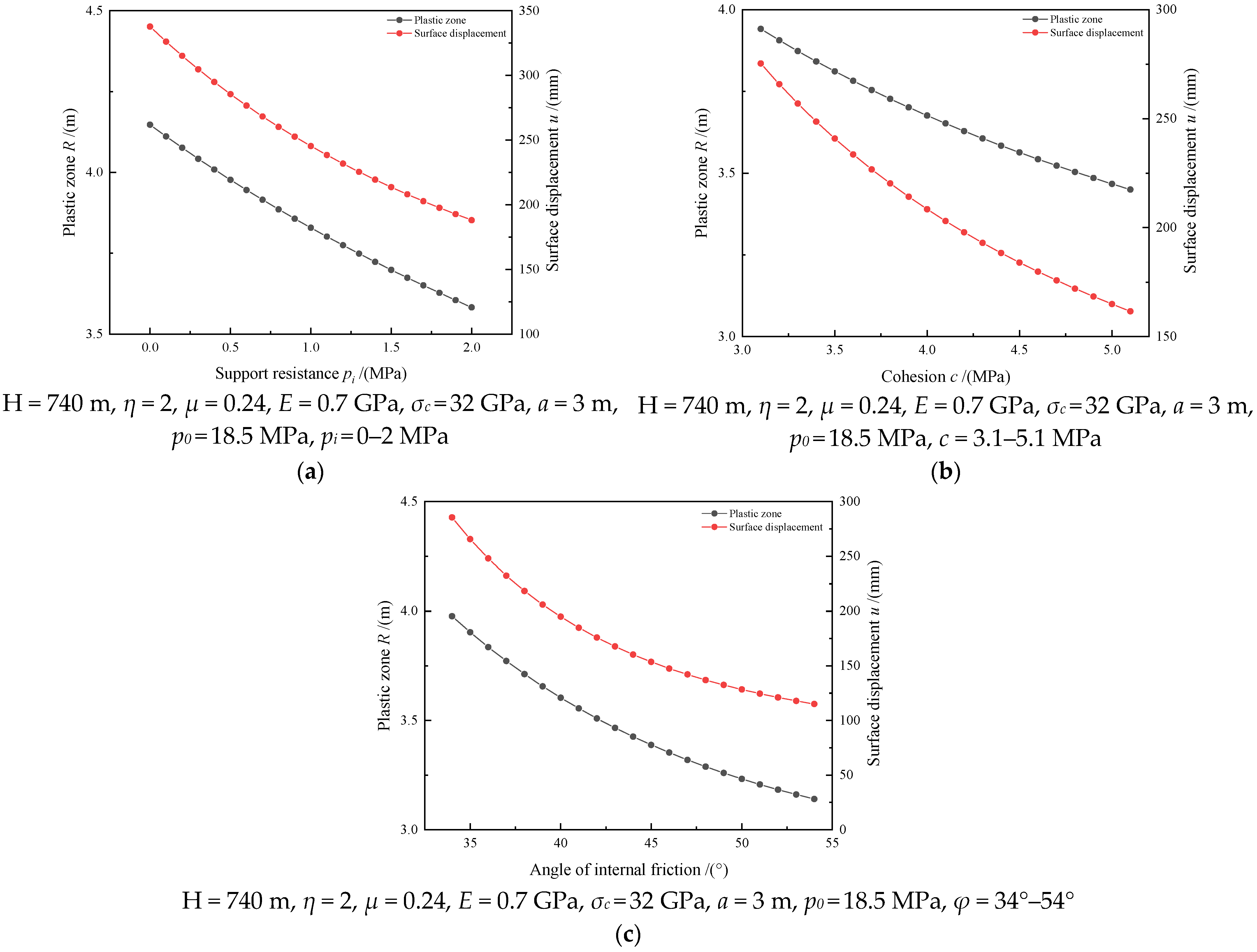
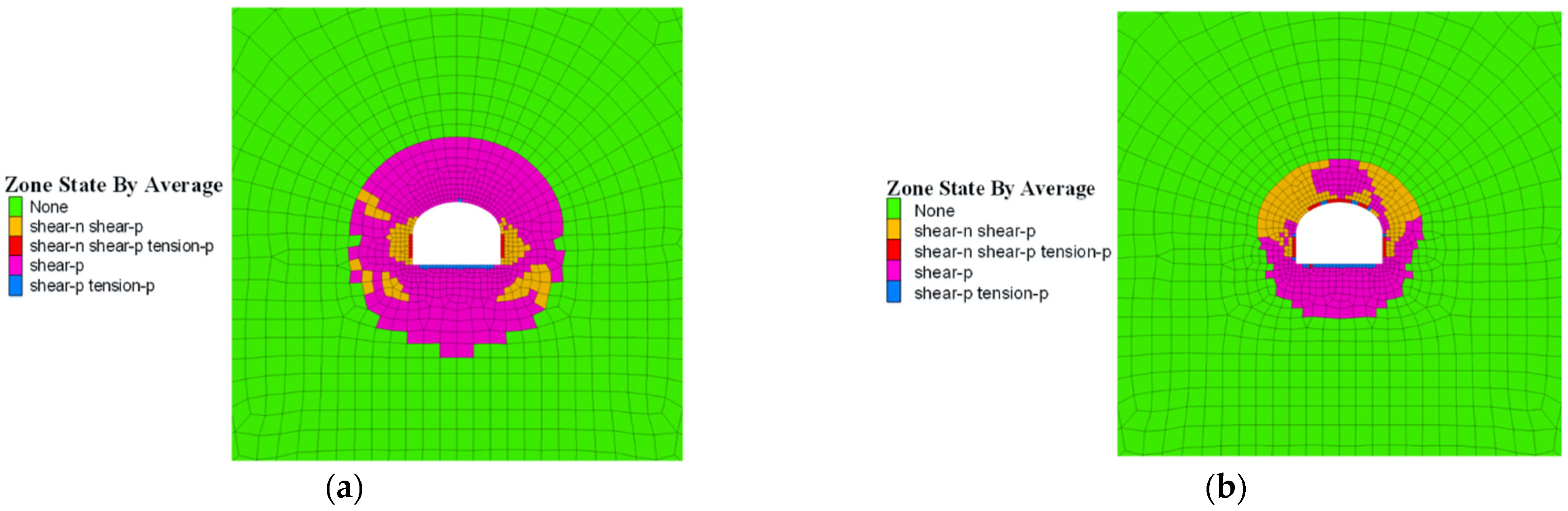
2.3. Analysis of Roadway Failure Mechanism

According to the field monitoring and research of the west wing transportation roadway and the analysis of similar roadways at home and abroad, the specific factors affecting the deformation and instability of the west wing transportation roadway are as follows: (1) The burial depth is large. The elevation of the transportation roadway in the west wing is about 740 m, and the surrounding rock pressure of the roadway is large, which makes the surrounding rock loose and difficult to control [25,26]. (2) The strength of the surrounding rock is low. The surrounding rock of the transportation roadway in the west wing is mainly composed of mudstone, sandstone and siltstone, with low strength and poor stability [27,28]. (3) Unreasonable roadway support mode. The original support scheme of the west wing transportation roadway adopts the support method of a bolt, anchor mesh and shotcrete to reinforce the surrounding rock of the roadway, which is mainly passive support and cannot fully mobilize the self-supporting capacity of the surrounding rock.

3. Roadway Stability Control

3.1. Roadway Stability Control Technology

The section of the west wing transport roadway is a three-center arch. According to the elastoplastic theory [29], the displacement of the roadway surface and the radius of the plastic zone can be expressed as follows:
R = a [ ( p 0 + c cot φ ) ( 1 sin φ ) p i + c cot φ ] 1 sin φ 2 sin φ
u = B 0 R ( R a ) ( 1 + η )
K = 1 + sin φ 1 sin φ
B 0 = ( 1 + μ ) [ ( K 1 ) P 0 + σ C ] ( K + 1 ) E
Combined with Formulas (1)–(4), we can obtain the following:
u = ( 1 + μ ) [ ( 1 + sin φ 1 sin φ 1 ) p 0 + σ c ] R ( 2 + η ) E ( 1 + sin φ 1 sin φ + 1 ) a ( 1 + η )
In the formula, a—equivalent radius, m; p0—original rock stress, MPa; c—cohesion, MPa; φ—internal friction angle, °; pi—support resistance, MPa; η—shearing gradient; µ—Poisson′s ratio; R—radius of the plastic zone, m; E—modulus of elasticity, GPa; u—roadway surface displacement, m; K—side pressure coefficient; and σc—compressive strength, MPa.
From Formulas (1) and (5), it can be seen that the support resistance pi, cohesion c and internal friction angle φ will affect the size of the plastic zone radius R and surface displacement u of the roadway. Therefore, the change law of the plastic zone radius R and surface displacement u of the roadway can be studied by changing the support resistance pi, cohesion c and internal friction angle φ. The relationship curves of support resistance pi, cohesion c and internal friction angle φ with plastic zone radius R and roadway surface displacement u are shown in Figure 6.
It can be seen from Figure 6 that when the cohesion c and the friction angle φ are constant, as the support resistance pi increases from 0 MPa to 2 MPa, the radius R of the plastic zone decreases from 4.15 m to 3.58 m, and the surface displacement u decreases from 337.72 mm to 188.06 mm. When the support resistance pi and friction angle φ are constant, as the cohesion c increases from 3.1 MPa to 5.1 MPa, the plastic zone radius R decreases from 3.94 m to 3.45 m, and the surface displacement u decreases from 275.3 mm to 161.62 mm. When the support resistance pi and cohesion c are constant, with the increase in friction angle φ from 34° to 54°, the radius of plastic zone R decreases from 3.98 m to 3.14 m, and the surface displacement u decreases from 285.5 mm to 115.02 mm.

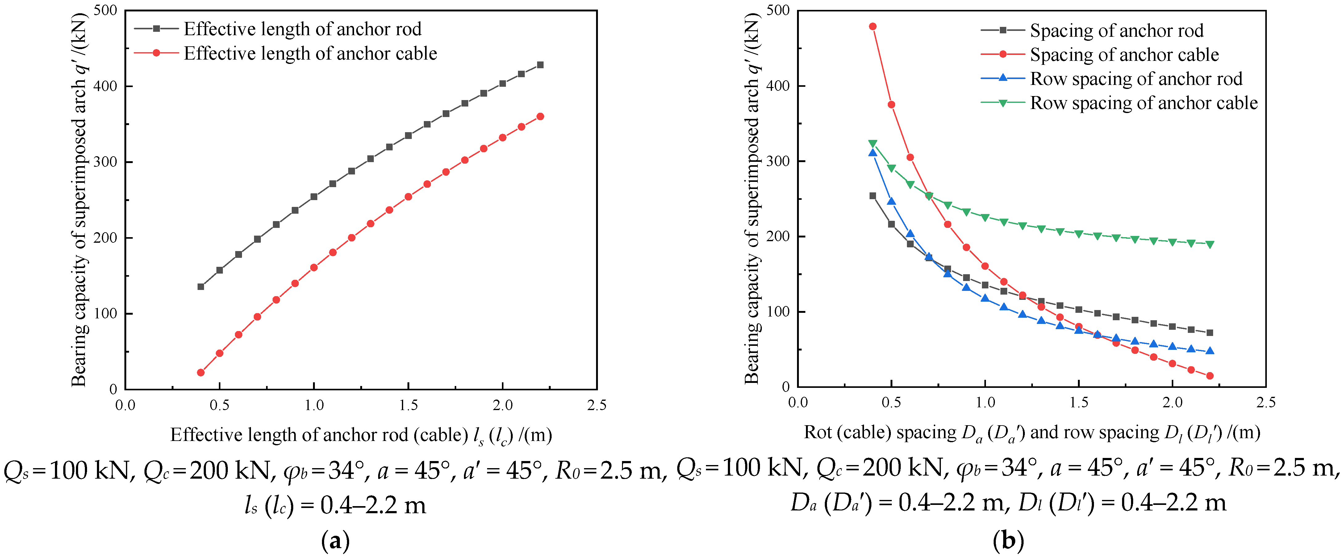
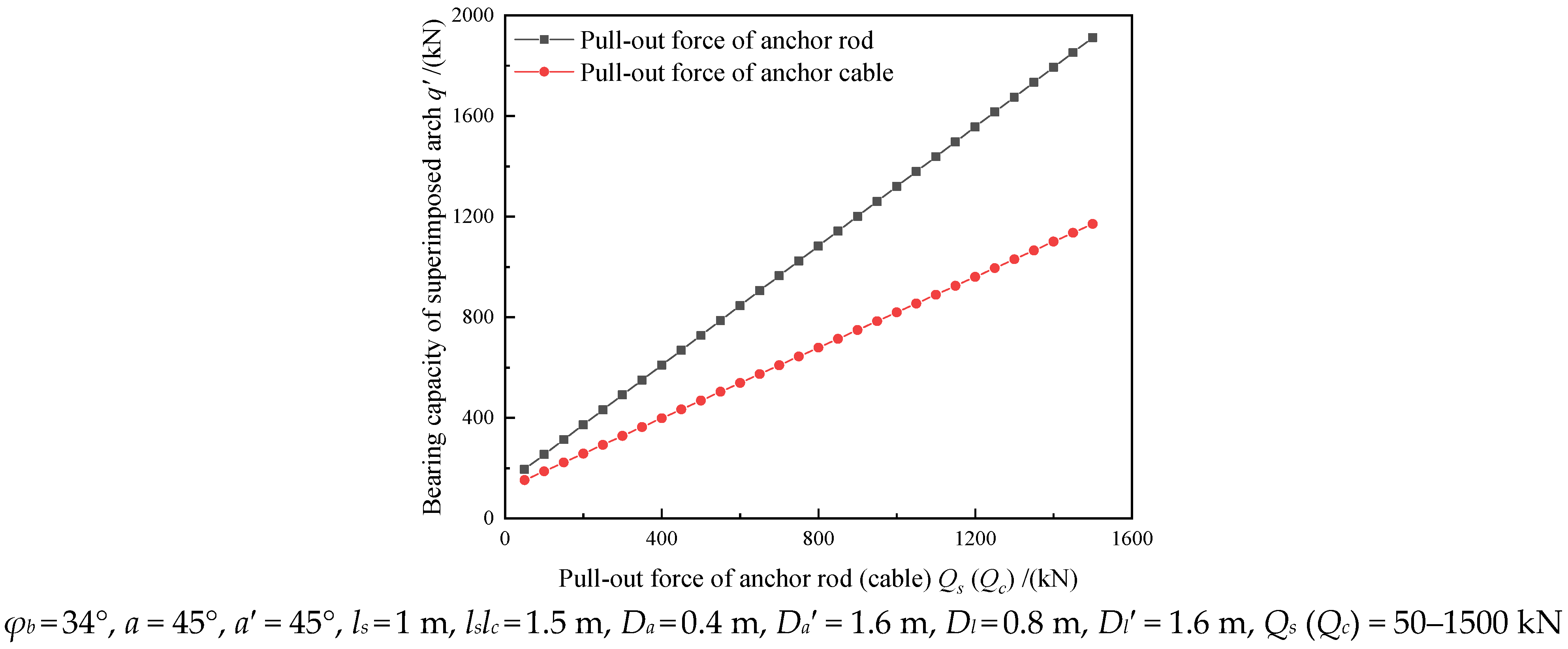
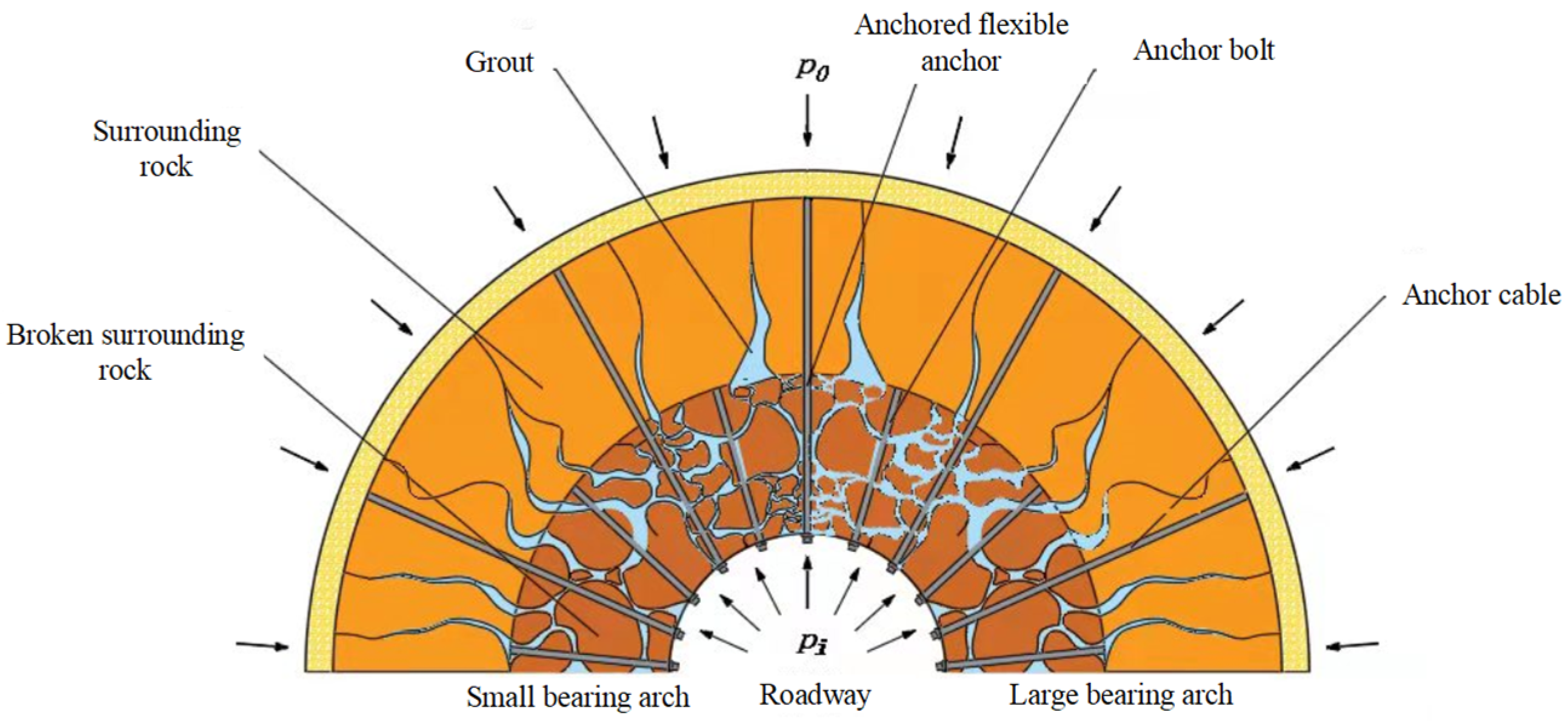
3.2. Superposition Community Stability Principle

Through the above analysis, it can be seen that although the radius R of the plastic zone and the surface displacement u of the roadway decrease with the increase in the support resistance pi, cohesion c and friction angle φ, the variation is also decreasing, indicating that only increasing the support resistance pi, cohesion c and friction angle φ can not maintain the long-term stability of the roadway. Therefore, while improving the support resistance pi, cohesion c and friction angle φ, increasing the bearing capacity of the superimposed arch, fully mobilizing the self-bearing capacity of the surrounding rock of the roadway, and maintaining the stability of the roadway should also be considered together. According to the theory of the superimposed arch [30], the bearing capacity of a superimposed arch can be expressed as follows:
q = 2 Q s ( 1 + sin φ b ) ( l s tan a D a ) D a D l tan a ( 1 sin φ b ) ( 2 R 0 + l s D a ) + 2 Q c ( 1 + sin φ b ) ( l c tan a D a ) D a D l tan a ( 1 sin φ b ) ( 2 R 0 + l c D a )
In the formula: q′—bearing capacity of the superimposed arch, kN; ls—effective length of anchor bolt, m; lc—effective length of anchor cable, m; Qs—pullout force of anchor bolt, kN; Qc—pulling force of anchor cable, kN; Da—anchor spacing, m; Dl—bolt row spacing, m; Da′—anchor cable spacing, m; Dl′—anchor cable spacing, m; a—anchor bolt control angle, 45°; a′—anchor cable control angle, 45°; φb—internal friction angle of rock in the loose zone, taken as 34°; and R0—roadway radius, m. (The effective length of the bolt and anchor cable refers to the effective length of the part of the bolt and anchor cable in the surrounding rock playing the role of anchoring).
In order to study the influence of the effective length ls (lc) of the anchor bolt (cable) and the row spacing Da (Da′) of the anchor (cable) on the bearing capacity q′ of the superimposed arch, the relationship curves between the effective length ls (lc) of the anchor bolt (cable), the spacing Da (Da′) of the anchor (cable), the row spacing Dl (Dl′) and the bearing capacity q′ of the superimposed arch are drawn, as shown in Figure 7.
When the spacing Da (Da′) and the row spacing Dl (Dl′) are fixed, the bearing capacity q′ of the superimposed arch increases with the increase in the effective length ls (lc) of the bolt (cable). When the effective length ls (lc) and the row spacing Dl (Dl′) of the anchor bolt (cable) are constant, with the increase in the spacing Da (Da′) of the anchor bolt (cable), the bearing capacity q′ of the superimposed arch decreases from 254.18 kN (479.04 kN) to 72.27 kN (14.96 kN), which decreases by 181.9 kN (464.09 kN). When the effective length ls (lc) and spacing Da (Da′) of the anchor bolt (cable) is constant, with the increase in the row spacing Dl (Dl′) of the anchor bolt (cable), the bearing capacity q′ of the superimposed arch decreases from 310.29 kN (324.53 kN) to 47.19 kN (190.55 kN), which decreases by 263.09 kN (133.98 kN). From Figure 6b, it can be seen that although the bearing capacity q′ of the superimposed arch decreases with the increase in the spacing Da (Da′) and the row spacing Dl (Dl′) of the anchor bolt (cable), and although the bearing capacity q′ of the superimposed arch decreases with the increase in the spacing Da (Da′) and the row spacing Dl (Dl′) of the anchor bolt (cable), the variation also decreases, so selecting the appropriate row spacing can not only improve the bearing capacity q′ of the superimposed arch, but also reduce the use of anchor bolts (cable) and save construction costs.
q = ln s Q s + ln c Q c
In the formula:
ln s = 2 ( 1 + sin φ b ) ( l s tan a D a ) D a D l tan a ( 1 sin φ b ) ( 2 R 0 + l s D a )
ln c = 2 ( 1 + sin φ b ) ( l c tan a D a ) D a D l tan a ( 1 sin φ b ) ( 2 R 0 + l c D a )
where lns is the degree of tension concentration coefficient of the anchor bolt, and lnc is the degree of tension concentration coefficient of the anchor cable.
In order to study the influence of Qs (Qc) on q′, the relationship curve between the pullout force Qs (Qc) of the bolt (cable) and the bearing capacity q′ of the superimposed arch is drawn, as shown in Figure 8.
From Figure 8, it can be seen that the bearing capacity q′ of the superimposed arch increases with the increase in the pullout force Qs (Qc) of the bolt (cable). The greater the pullout force Qs (Qc) of the bolt (cable), the greater the bearing capacity q′ of the superimposed arch. In the process of roadway surrounding rock support, the bolt or anchor cable with greater strength of the bolt body is selected.
According to the above analysis, in order to maintain the long-term stability of the west wing transportation roadway in Yuandian No. 2 Coal Mine, a new support scheme that can not only improve the support resistance pi, but also increase the cohesion c, internal friction angle φ and self-bearing capacity of the surrounding rock of the roadway is needed; that is, a “bolt (cable) + anchor net + anchor flexible bolt + shotcrete support” combined support. In the combined support scheme, the small pressure arch is formed by the mutual extrusion between the anchor bolt and the anchor bolt, the anchor bolt and the broken surrounding rock, and the large pressure arch is formed by the mutual compression combination between the anchor-grouting flexible anchor bolt and the anchor cable. Through high-pressure grouting, the slurry penetrates into the broken surrounding rock and even passes through the cracks with poor connectivity to form splitting grouting and broken surrounding rock. The small pressure arch formed between the anchor bolt and the anchor bolt, the small pressure arch formed between the anchor bolt and the broken surrounding rock, the large pressure arch formed between the anchor bolt and the anchor cable and the broken surrounding rock bonded by the grouting slurry are superimposed together to form a superposition community, which jointly maintains the stability of the roadway. The schematic diagram of the superposition community structure is shown in Figure 9.

3.3. Support Technical Scheme

3.3.1. Support Scheme

Based on the research background of the west wing transportation roadway of Yuandian No.2 Coal Mine of Huaibei Mining Co., Ltd., this paper puts forward the superposition combined support scheme of “bolt (cable) + anchor net + anchor flexible bolt + shotcrete support”. This scheme innovatively puts forward the new combination mode of “bolt (cable) + anchor flexible bolt” to maintain the stability of the surrounding rock of the roadway.

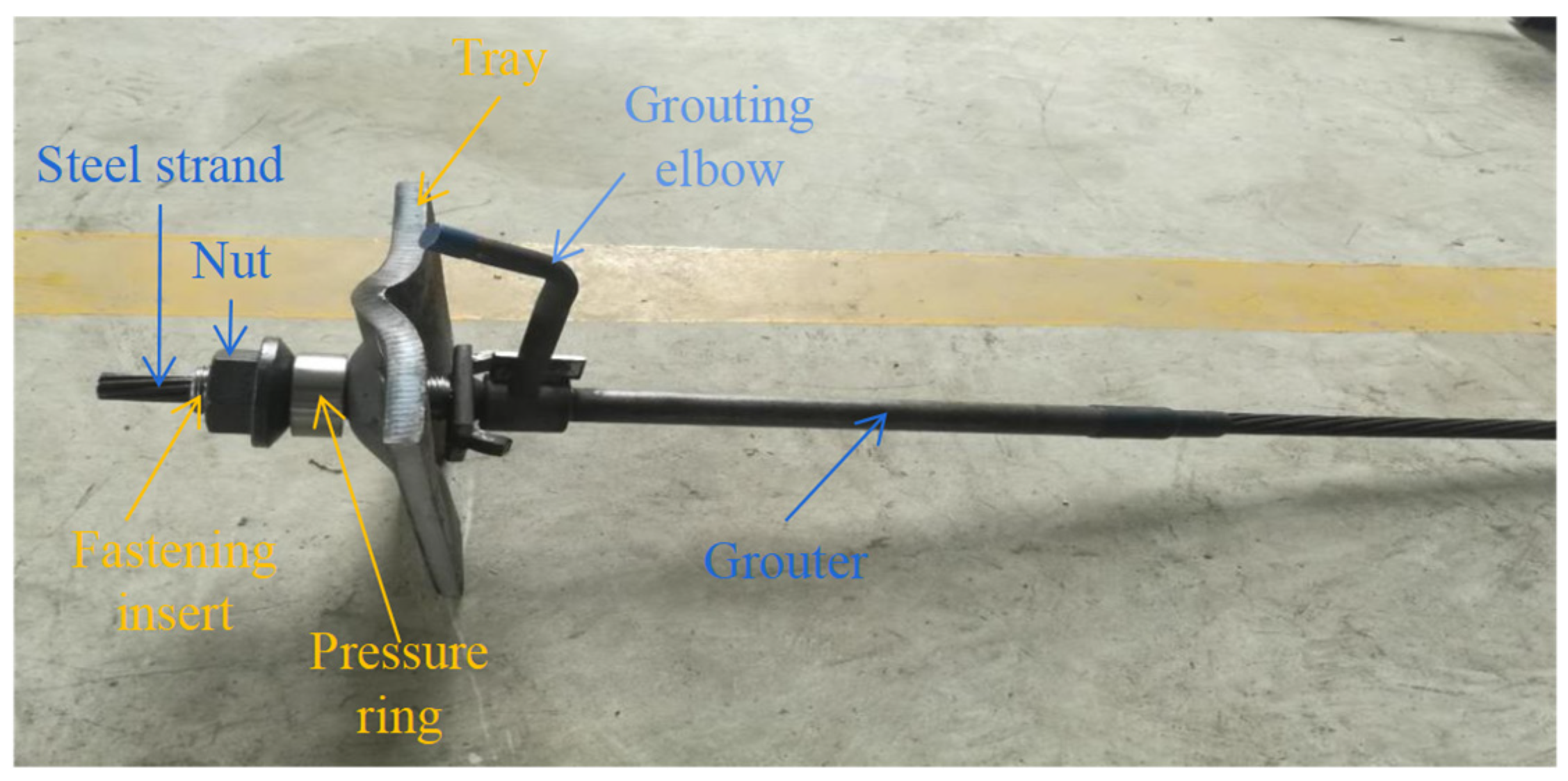
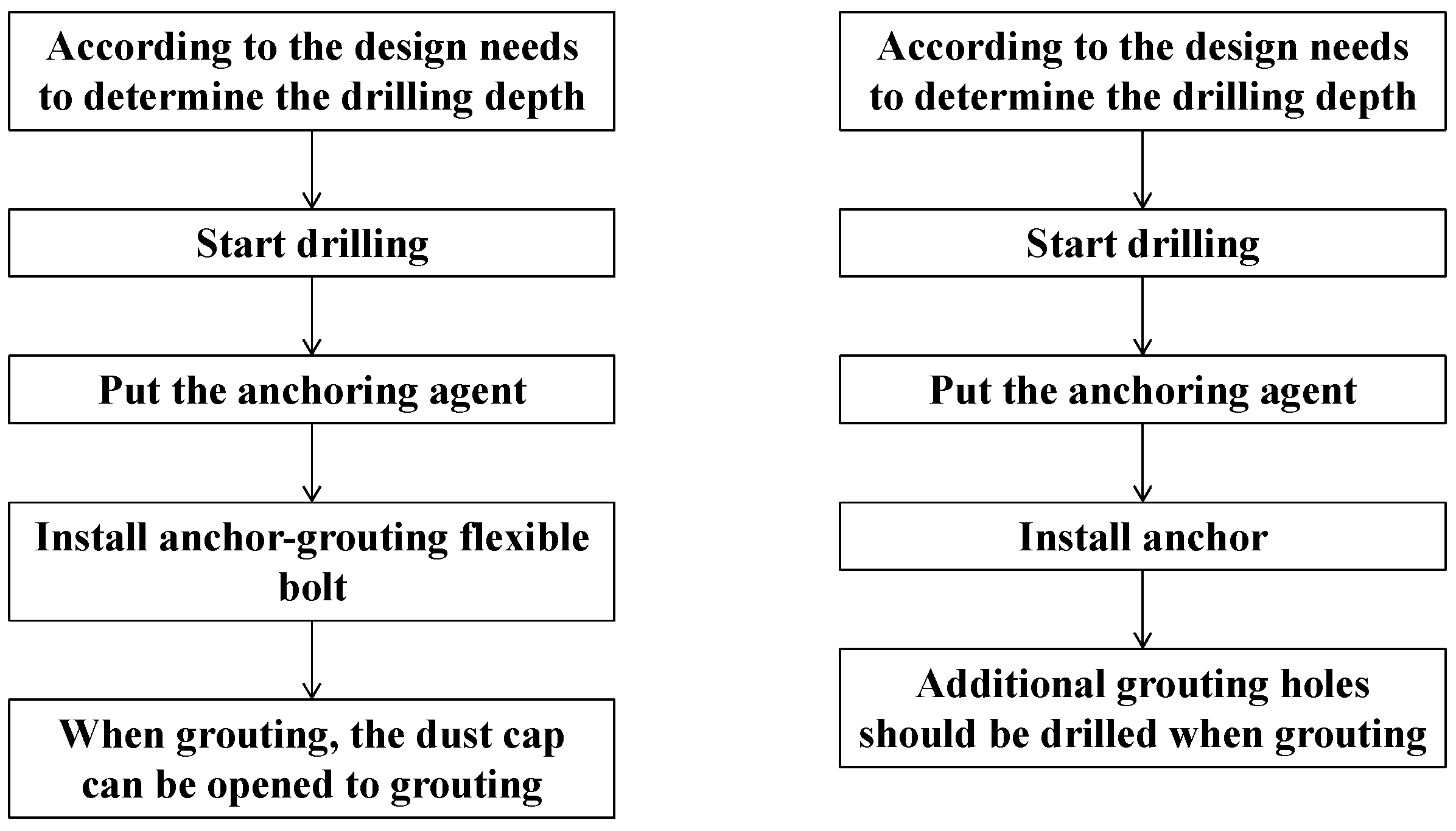
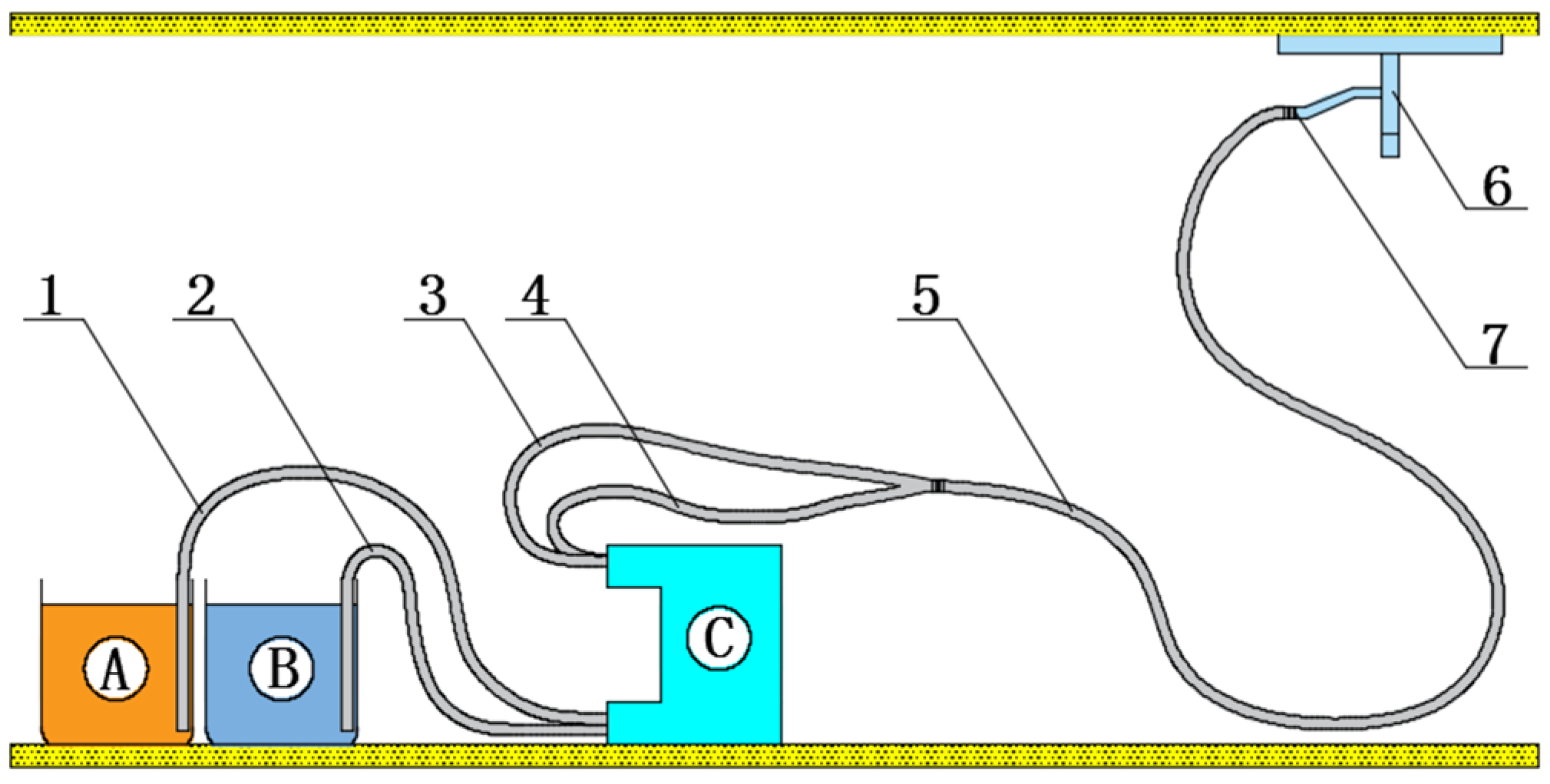
3.3.2. Anchoring Flexible Bolt Technology

As shown in Figure 10, the bolt-grouting flexible bolt is composed of a steel strand bolt, fastening sleeve, nut, pressure ring, tray, self-locking plate and grouting device. With a high-strength steel strand as the bolt body, it is a kind of high-prestress anchoring bolt. Through the combination of nut, tray, self-locking plate and baffle on the joint of the grouting device, the steel strand bolt body does not rotate when tightening the nut, which can meet the design torque force requirements. The grouting device can facilitate grouting and realize the organic combination of full-length anchoring of bolt and grouting reinforcement of surrounding rock. In addition, the anchor-grouting flexible bolt adopts high-pressure grouting, and the grouting pressure is more than 3 MPa. Under the condition of high-pressure grouting, the slurry can not only flow through the gap between the broken surrounding rock but also pass through the cracks with poor connectivity to form splitting grouting and combine them to form a whole.
The installation comparison diagram of the anchored flexible bolt and ordinary bolt is shown in Figure 11. Compared with ordinary bolts, the structure of the anchored flexible bolt is simple, the construction is convenient and efficient, and the cost of the anchored flexible bolt is much lower than that of a traditional bolt and grouting support. In the early stage, it is used as an ordinary support bolt, and in the later stage, it is used as a grouting anchor cable. It only needs to be drilled and installed once, and it is not necessary to install the grouting bolt again, which greatly simplifies the construction steps. After installation, it can bear the load immediately, and the support strength is far more than that of the same specification ordinary grouting anchor bolt (cable). After grouting, the support is formed as a whole, which is very beneficial to ensure the support effect, which is far greater than the support effect of an ordinary anchor bolt (cable). The new bolt structure is adopted to minimize the diameter of the bolt body under the premise of ensuring smooth grouting, and the required installation aperture is small. The bolt structure itself meets the requirements of high-pressure grouting, and truly realizes the integration of anchor and grouting. Grouting is convenient and timely, and grouting can be arranged at a certain distance behind the head, so that the roadway can be reinforced in advance when it is only deformed but not destroyed, reducing the amount of roadway maintenance. The mechanical properties parameters of the anchor-grouting flexible bolt are shown in Table 1.

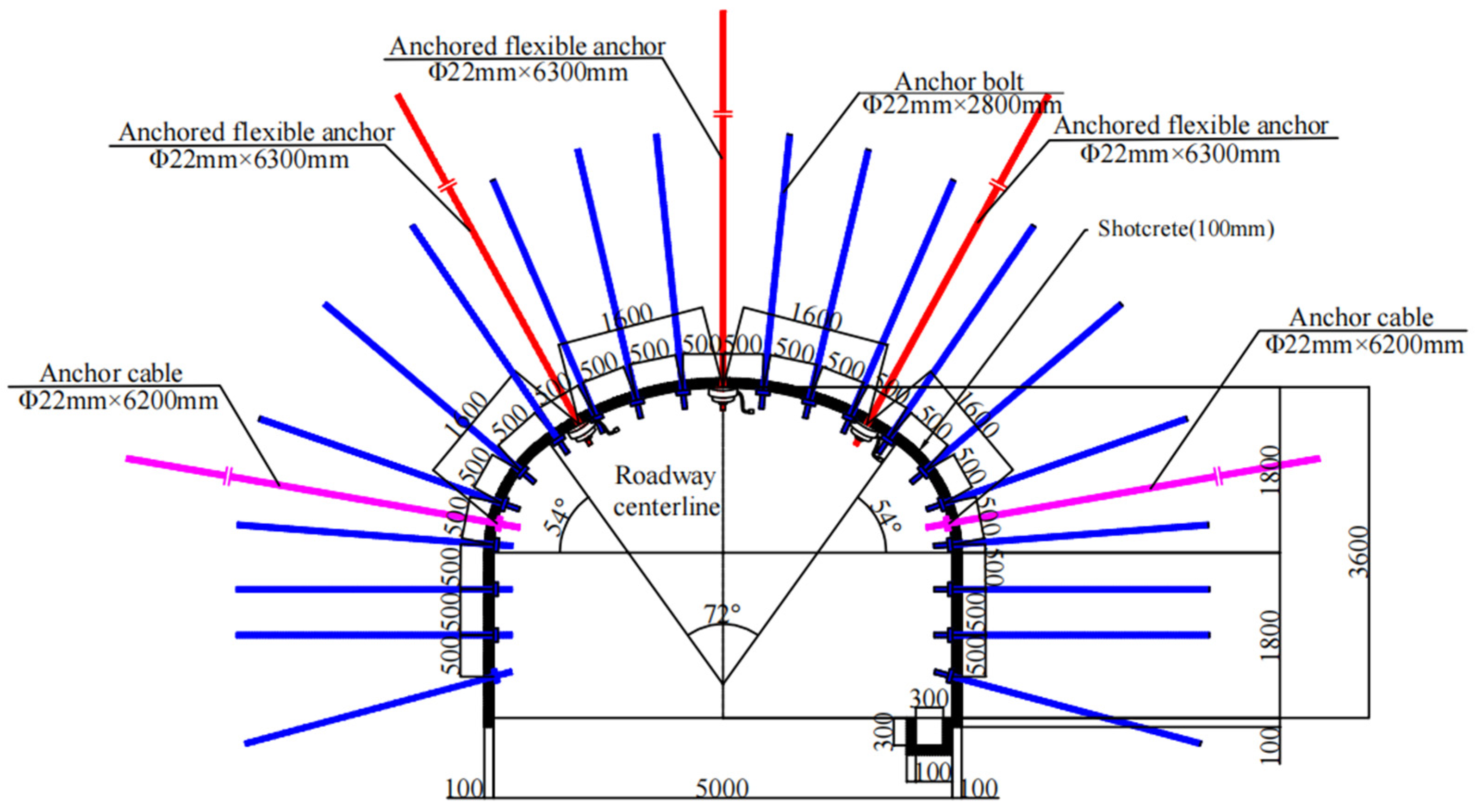
3.3.3. Combined Support Technology Design

After the above analysis, it is finally determined that the whole section of the west wing transport roadway is supported by a Φ22 mm × 2800 mm high-strength screw steel bolt, the row spacing is 500 mm × 800 mm, and each bolt is anchored by two K2950 resin anchoring agent. Two Φ22 mm × 6200 mm anchor cables are driven into the two sides, and the spacing between rows is 1600 mm × 1600 mm. Each anchor cable is anchored by one K2950 type and two Z2950 type anchoring agents; the length of all anchoring agents is 30 mm. At the top of the roadway, Φ22 mm × 6300 mm anchored flexible bolts were driven, with an interval of 1600 mm × 1600 mm and three bolts in a row. Welded warp and weft mesh with 100 mm × 100 mm steel bar is used. The surrounding rock of the concrete closed roadway with a strength grade of C20 is used. The thickness of the initial spray layer is 30–50 mm, and the secondary spray is 100 mm. Youante is used as grouting material. Youante is divided into A material and B material. Before grouting, A and B materials are, respectively, placed in different mixing barrels for mixing. After mixing, they are mixed together for grouting. The grouting time depends on the depth of the borehole and the site conditions. It is characterized by high stability, strong permeability, quick effect, fast solidification speed, high solidification strength and green environmental protection. The grouting schematic diagram is shown in Figure 12. The specific process is as follows: grouting preparation → knocking → installing grouting pipe → connecting injection gun and grouting pump with high-pressure hose → inserting two pipettes into the barrel containing Youante A material and B material, respectively → opening pump grouting → washing machine after grouting → stopping pump → dismantling injection gun. According to the deformation characteristics of the surrounding rock of the west wing transportation roadway, the grouting time should be 15 to 20 days after the excavation of the roadway section, and the final support section is shown in Figure 13.

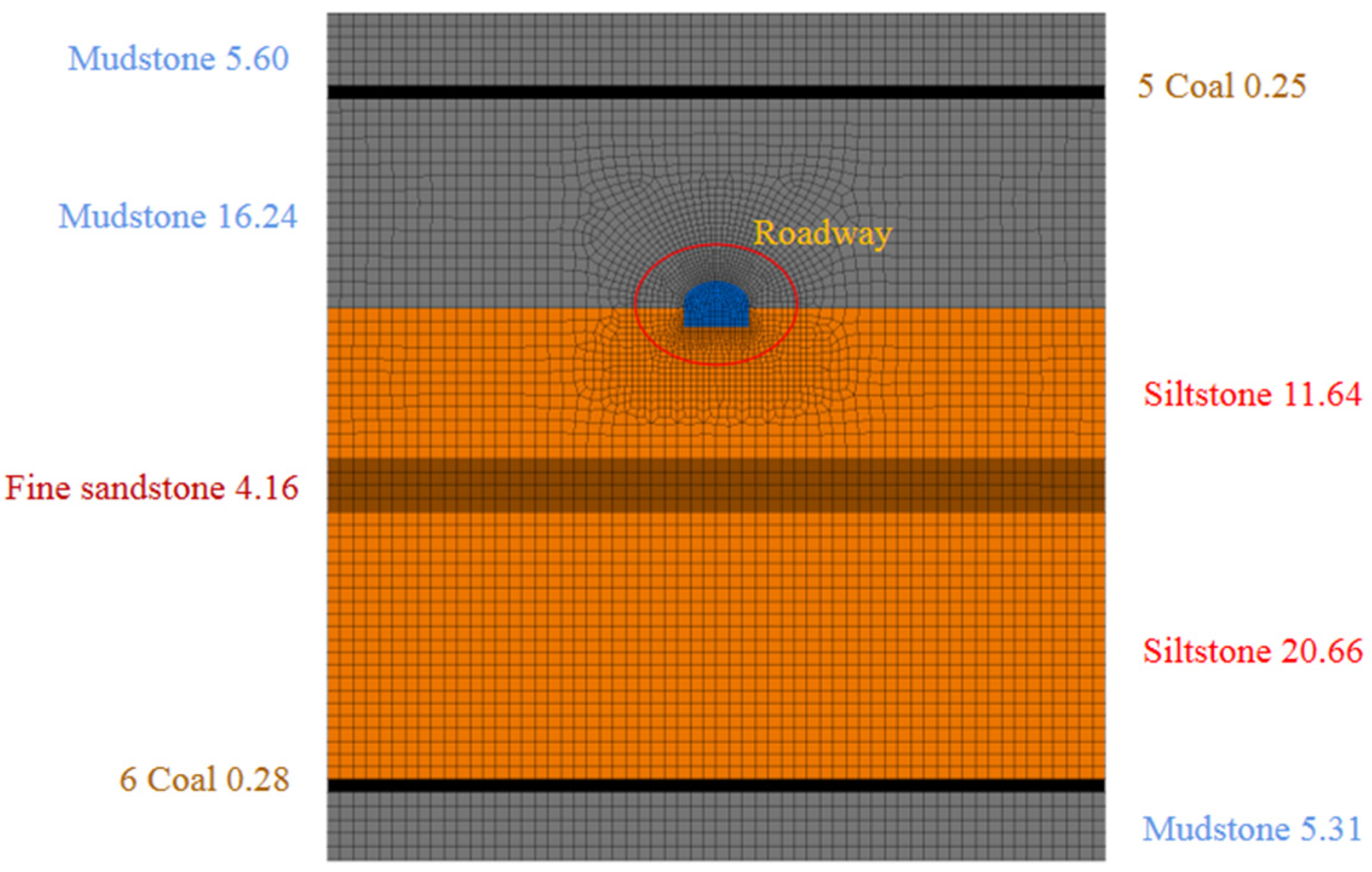
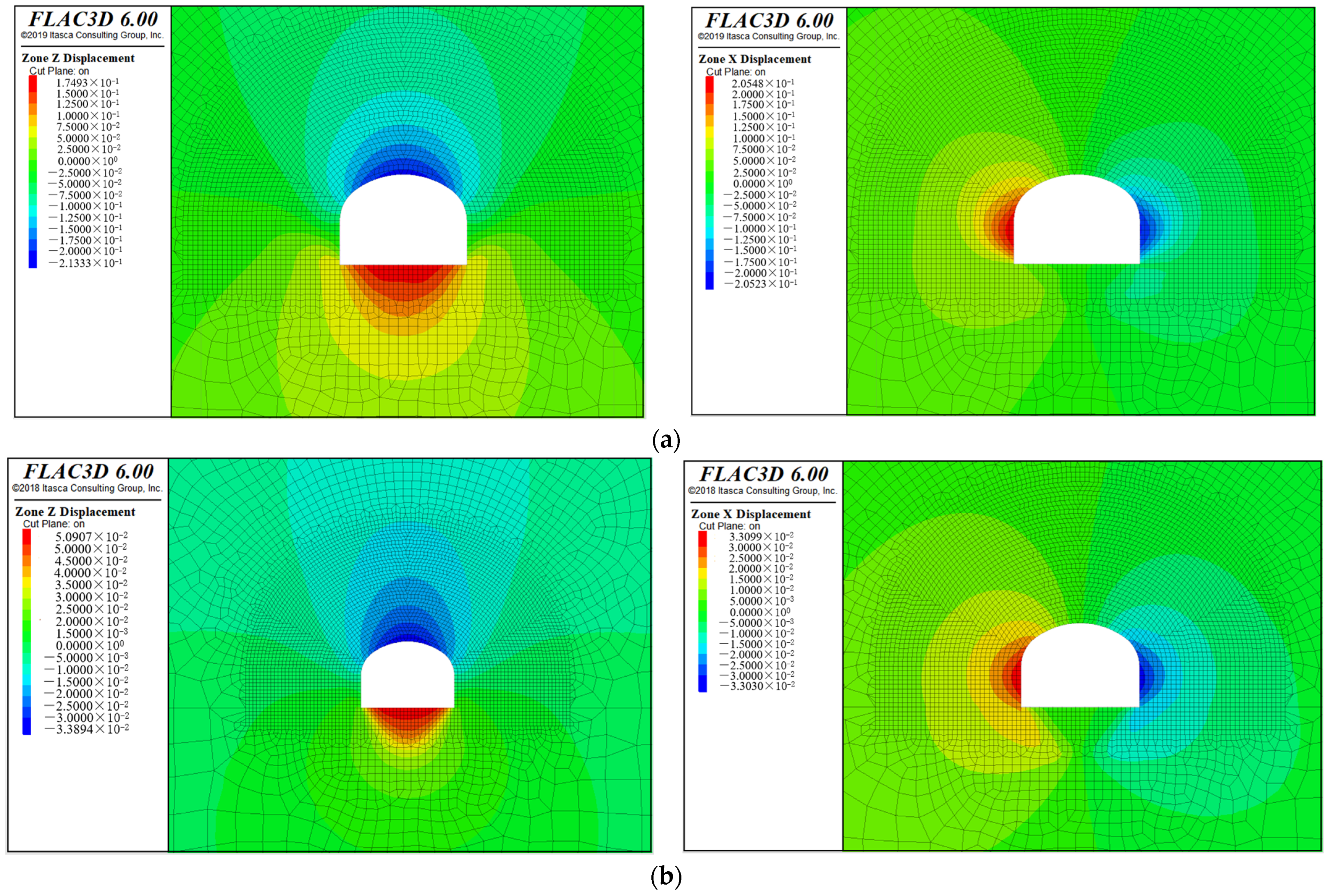
4. FLAC 3D Numerical Simulation

According to the geological conditions of the west wing transportation roadway, the numerical simulation model shown in Figure 14 is established by using FLAC 3D numerical simulation software. The section of the west wing transportation roadway adopts a three-center arch, the roadway width is 5 m, the wall height is 1.8 m, and the model size is 60 m × 20 m × 65.6 m. The roadway section adopts a 2800 mm bolt to simulate support, the spacing between rows is 500 mm × 800 mm, the two sides are driven into a 6200 mm anchor cable, the spacing between those rows is 1600 mm × 1600 mm, and the top of the roadway is driven into a 6300 mm anchor-grouting flexible bolt, the spacing those between those rows is 1600 mm × 1600 mm, three in a row, and the simulated support structure is shown in Figure 15. According to the surrounding rock condition of the west wing transportation roadway, the model can be divided into eight layers, which are mudstone, 5 coal, mudstone, siltstone, fine sandstone, siltstone, 6 coal and mudstone, from top to bottom. The model adopts the Mohr–Coulomb criterion. The displacement constraints in the Y direction and X direction are applied to the front and back, left and right of the model, respectively. The displacement constraints in the Z direction are applied to the bottom, and the stress constraints are applied to the top. The buried depth of the simulated roadway is 740 m, and the load applied to the top of the model is 18.5 MPa. The model has 503,810 cells and 534,693 nodes. In order to improve the efficiency of model calculation and better reflect the changes in stress and displacement of surrounding rock around the roadway, the surrounding rock of the roadway is set to a smaller grid size, the minimum size of which is 0.2 m × 0.2 m, and the remaining grid size is increased exponentially with the distance from the roadway, up to a maximum size of 1 m × 1 m. The corresponding physical parameters of each rock layer are given to the numerical simulation model. The physical and mechanical parameters of the required rock mass mainly include the following: density ρ, bulk modulus K, shear modulus G, cohesion c, internal friction angle φ and tensile strength t. The mechanical parameters of rock strata are determined according to the laboratory results, and the rock strength is transformed into rock mass strength through certain weakening. Finally, the effective physical and mechanical parameters of rock mass are determined, as shown in Table 2.
The vertical and horizontal displacement nephogram of numerical simulation before and after the support of the west wing transport roadway is shown in Figure 16. According to the analysis of the numerical simulation displacement cloud diagram of the roadway before support, the maximum roof subsidence of the west wing transportation roadway is 213.33 mm, the maximum floor heave is 174.93 mm, and the maximum two-side displacement is 410.71 mm. After the support, the maximum subsidence of the roadway roof is 33.894 mm, the maximum floor heave is 50.907 mm, and the maximum displacement of the two sides is 66.129 mm. Compared to before the roadway support, the maximum subsidence of the roof is reduced by 179.436 mm, and the maximum floor heave is reduced by 124.023 mm. At the same time, the maximum displacement of the two sides is reduced by 344.581 mm.
Figure 17 shows the distribution of plastic zone in numerical simulation before and after the support of the west wing transportation roadway. It can be seen from the figure that the plastic zone range is obviously reduced after the combined support scheme is adopted, and the overall strength of the surrounding rock of the roadway is improved after the support. Through numerical simulation, it can be seen that the combined support scheme of “bolt (cable) + anchor net + anchor flexible bolt + shotcrete” can effectively reduce the distribution range of the plastic zone of the roadway′s surrounding rock and effectively control the deformation of roadway′s surrounding rock.

5. Industrial Experiment

In order to verify the on-site support effect of the combined support scheme of “bolt (cable) + anchor net + anchor-grouting flexible bolt + shotcrete”, Y26 + 80 m–Y26 + 200 m of the west wing transportation roadway was selected as the experimental section. The surface and deep displacement changes after roadway support were observed, and six surface displacement monitoring stations and one deep displacement monitoring station were set up. The layout of the observation station of the west wing transportation roadway is shown in Figure 18. The displacement observation method is as follows: the distance between the roof and floor of the roadway is measured by steel tape, and the distance between the ends of the two sides of the roadway is measured by leather tape. Through the observation of 60 days, the surface displacement monitoring results are shown in Figure 19. The maximum displacement of the top and bottom is 30.7 mm, and it tends to be stable after 24 days. The maximum displacement of the two sides is 27.1 mm. The deformation is large in the first 7 days, and tends to be stable after 26 days.
The monitoring results of deep displacement are shown in Figure 20. According to the monitoring data, the maximum displacement at 1 m in the shallow part is 11.8 mm, and the maximum displacement at 7 m in the deep part is 18.5 mm. In the early stage, due to the influence of excavation disturbance, the deep displacement increment is large. When the measuring point is about 80 m away from the excavation surface, the displacement gradually tends to be gentle. The displacement change trend of the surrounding rock of the roadway within 1~7 m is basically consistent, the change is within 7 mm, and there is no separation between the rock layers.
From the observation results of surface and deep displacement during the excavation of the experimental section of the west wing transportation roadway, it can be seen that during the observation period, the deformation of the roadway in the experimental section was small, and no cracking of the side and roof rupture occurred. The field observation data show that the maximum displacement of the two sides and the roof and floor of the roadway in the experimental section is within 31 mm, and the roadway is stable. The deep displacement observation shows that the integrity of the surrounding rock of the roadway after support is better, and the support scheme has an obvious inhibitory effect on the fracture expansion of the rock mass, which plays a role in strengthening the surrounding rock. The support effect of the experimental section is shown in Figure 21.

6. Conclusions

(1) Aiming at the characteristics of large buried depth and low strength of the surrounding rock in the west wing transportation roadway of Yuandian No.2 well coal mine, the anchor-grouting flexible bolt is proposed to solve the stability control problem of surrounding rock in this kind of roadway. Compared with ordinary anchor bolts, the structure of anchor-grouting flexible bolts is a simple and convenient construction. It is a kind of high pre-tightening anchoring bolt with a high-strength steel strand as the bolt body. It only needs to be installed once, and it is convenient to install a grouting bolt without re-drilling. At the same time, a new bolt structure is adopted to minimize the diameter of the bolt body under the premise of ensuring smooth grouting, so as to realize the integration of bolting and grouting.
(2) In order to maintain the stability of the roadway in the west wing transportation roadway, a combined support scheme of “bolt (cable) + anchor net + bolt-grouting flexible bolt + shotcrete support” was proposed, and its support mechanism was analyzed. The results show that the small pressure arch formed between the bolt and the bolt, the bolt and the broken surrounding rock, the large pressure arch formed between the bolt-grouting flexible bolt and the anchor cable, and the broken surrounding rock bonded by the grouting slurry are superimposed together to form a superimposed community, so as to realize the combined support to jointly control the deformation of the roadway′s surrounding rock.
(3) FLAC 3D numerical simulation and field monitoring show that the surface displacement monitoring of the roadway after adopting the combined support scheme of “bolt (cable) + anchor net + anchor injection flexible bolt + shotcrete support” shows that the maximum roof-to-floor convergence is only 30.7 mm, and the maximum two-side convergence is 27.1 mm. The deep displacement monitoring of the roadway shows that the trend change in deep displacement within 1–7 m is basically the same, and the change amount is within 7 mm, which can effectively control the stability of the roadway, improve the self-bearing capacity of surrounding rock and maintain the long-term stability of the roadway. The combined support scheme has a certain reference value for other similar roadways.

Author Contributions

Conceptualization, H.Z. and Y.L.; methodology, H.Z. and X.W.; software, H.Z. and Y.W.; first draft preparation, H.Z.; writing—original draft preparation, H.Z.; visualization, H.Z. and S.Y.; supervision, Y.L. All authors have read and agreed to the published version of the manuscript.

Funding

This research has been supported by the National Natural Science Foundation of China (Grant No. 52174102, 51874002), the Anhui Provincial Key Research and Development Plan (Grant No. 2022m07020007) and the Graduate Innovation Fund (Grant No. 2021CX2014).

Institutional Review Board Statement

Not applicable.

Informed Consent Statement

Not applicable.

Data Availability Statement

Not applicable.

Acknowledgments

We thank Huaibei Mining Co., Ltd. Yuandian Well 2 Coal Mine for providing the test platform, and thank Zhao Nannan for his help and data support in the fieldwork. The authors of this article are also so grateful to the anonymous reviewers for their valuable comments and modification suggestions on the improvement of this paper.

Conflicts of Interest

The authors declare no conflict of interest.

References

  1. Sun, Y.; Li, G.; Zhang, J.; Xu, J. Failure Mechanisms of Rheological Coal Roadway. Sustainability 2020, 12, 2885. [Google Scholar] [CrossRef] [Green Version]
  2. Shreedharan, S.; Kulatilake, P.H.S.W. Discontinuum—Equivalent Continuum Analysis of the Stability of Tunnels in a Deep Coal Mine Using the Distinct Element Method. Rock Mech. Rock Eng. 2016, 49, 1903–1922. [Google Scholar] [CrossRef]
  3. Yu, K.; Ren, F.; Puscasu, R.; Lin, P.; Meng, Q. Optimization of combined support in soft-rock roadway. Tunn. Undergr. Space Technol. 2020, 103, 103502. [Google Scholar] [CrossRef]
  4. Wu, G.; Chen, W.; Jia, S.; Tan, X.; Zheng, P.; Tian, H.; Rong, C. Deformation characteristics of a roadway in steeply inclined formations and its improved support. Int. J. Rock Mech. Min. Sci. 2020, 130, 104324. [Google Scholar] [CrossRef]
  5. Kang, H.; Wu, Y.; Gao, F.; Jiang, P.; Cheng, P.; Meng, X.; Li, Z. Mechanical performances and stress states of rock bolts under varying loading conditions. Tunn. Undergr. Space Technol. 2016, 52, 138–146. [Google Scholar] [CrossRef]
  6. Wang, P.; Zhang, N.; Kan, J.; Wang, B.; Xu, X. Stabilization of Rock Roadway under Obliquely Straddle Working Face. Energies 2021, 14, 5759. [Google Scholar] [CrossRef]
  7. Yang, X.; Pang, J.; Liu, D.; Liu, Y.; Tian, Y.; Ma, J.; Li, S. Deformation mechanism of roadways in deep soft rock at Hegang Xing′an Coal Mine. Int. J. Min. Sci. Technol. 2013, 23, 307–312. [Google Scholar] [CrossRef]
  8. Shen, B. Coal mine roadway stability in soft rock: A case study. Rock Mech. Rock Eng. 2014, 47, 2225–2238. [Google Scholar] [CrossRef]
  9. Chen, Y.; Meng, Q.; Xu, G.; Wu, H.; Zhang, G. Bolt-grouting combined support technology in deep soft rock roadway. Int. J. Min. Sci. Technol. 2016, 26, 777–785. [Google Scholar] [CrossRef]
  10. He, M.C.; Xie, H.P.; Peng, S.P.; Jiang, Y.D. Study on rock mechanics of deep mining. Chin. J. Rock Mech. Eng. 2005, 16, 2803–2813. [Google Scholar]
  11. Wang, Q.; Jiang, B.; Pan, R.; Li, S.C.; He, M.C.; Sun, H.M.; Qin, Q.; Yu, H.C.; Luan, Y.C. Failure mechanism of surrounding rock with high stress and confined concrete support system. Int. J. Rock Mech. Min. Sci. 2018, 102, 89–100. [Google Scholar] [CrossRef]
  12. Sun, X.M.; Liu, X.; Liang, G.F.; Wang, D.; Jiang, Y.L. Study on key parameters of thin coal seam roof cutting and pressure relief gob side entry retaining. J. Rock Mech. Eng. 2014, 33, 1449–1456. [Google Scholar]
  13. Guo, P.; He, M.; Wang, J. Study on Coupling Support Technique in the Roadway of Hecaogou No. 2 Coal Mine with Soft Roadway of Large Deformation. Geotech. Geol. Eng. 2018, 36, 1161–1173. [Google Scholar] [CrossRef]
  14. Wang, Z.; Wang, C.; Wang, X. Research on High Strength and Pre-stressed Coupling Support Technology in Deep Extremely Soft Rock Roadway. Geotech. Geol. Eng. 2018, 36, 3173–3182. [Google Scholar] [CrossRef]
  15. Zhang, S.; Yin, S. Analytical Approach Based on Full-Space Synergy Technology to Optimization Support Design of Deep Mining Roadway. Minerals 2022, 12, 746. [Google Scholar] [CrossRef]
  16. Wu, P.; Chen, L.; Li, M.; Wang, L.; Wang, X.; Zhang, W. Surrounding Rock Stability Control Technology of Roadway in Large Inclination Seam with Weak Structural Plane in Roof. Minerals 2021, 11, 881. [Google Scholar] [CrossRef]
  17. Wang, Q.; Pan, R.; Jiang, B.; Li, S.; He, M.; Sun, H.; Wang, L.; Qin, Q.; Yu, H.; Luan, Y. Study on failure mechanism of roadway with soft rock in deep coal mine and confined concrete support system. Eng. Fail. Anal. 2017, 81, 155–177. [Google Scholar] [CrossRef]
  18. Feng, X.; Ding, Z.; Hu, Q.; Zhao, X.; Ali, M.; Banquando, J.T. Orthogonal Numerical Analysis of Deformation and Failure Characteristics of Deep Roadway in Coal Mines: A Case Study. Minerals 2022, 12, 185. [Google Scholar] [CrossRef]
  19. Zhang, D.; Guo, W.; Zhao, T.; Zhao, Y.; Chen, Y.; Zhang, X. Energy Evolution Law during Failure Process of Coal–Rock Combination and Roadway Surrounding Rock. Minerals 2022, 12, 1535. [Google Scholar] [CrossRef]
  20. Qin, D.D.; Wang, X.F.; Zhang, D.S.; Chen, X.Y. Study on surrounding rock-bearing structure and associated control mechanism of deep soft rock roadway under dynamic pressure. Sustainability 2019, 11, 1892. [Google Scholar] [CrossRef] [Green Version]
  21. Skrzypkowski, K.; Zagórski, K.; Zagórska, A.; Apel, D.B.; Wang, J.; Xu, H.; Guo, L. Choice of the Arch Yielding Support for the Preparatory Roadway Located near the Fault. Energies 2022, 15, 3774. [Google Scholar] [CrossRef]
  22. Zhu, L.; Liu, C.; Gu, W.; Yuan, C.; Wu, Y.; Liu, Z.; Song, T.; Sheng, F. Research on Floor Heave Mechanisms and Control Technology for Deep Dynamic Pressure Roadways. Processes 2023, 11, 467. [Google Scholar] [CrossRef]
  23. Li, Y.; Zhang, D.; Fang, Q.; Yu, Q.; Xia, L. A physical and numerical investigation of the failure mechanism of weak rocks surrounding tunnels. Comput. Geotech. 2014, 61, 292–307. [Google Scholar] [CrossRef]
  24. Yang, S.Q.; Chen, M.; Jing, H.W.; Chen, K.F.; Meng, B. A case study on large deformation failure mechanism of deep soft rock roadway in Xi′an coal mine, China. Eng. Geol. 2017, 217, 89–101. [Google Scholar] [CrossRef]
  25. Zhao, C.; Liu, J.; Lyu, C.; Chen, W.; Li, X.; Li, Z. Experimental study on mechanical properties, permeability and energy characteristics of limestone from through-coal seam (TCS) tunnel. Eng. Geol. 2022, 303, 106673. [Google Scholar] [CrossRef]
  26. Zhao, C.; Liu, J.; Xu, D.; Zhang, L.; Lyu, C.; Ren, Y. Investigation on Mechanical Properties, AE Characteristics, and Failure Modes of Longmaxi Formation Shale in Changning, Sichuan Basin, China. Rock Mech. Rock Eng. 2022, 56, 1239–1272. [Google Scholar] [CrossRef]
  27. Lyu, C.; Liu, J.; Ren, Y.; Liang, C.; Liao, Y. Study on very long-term creep tests and nonlinear creep-damage constitutive model of salt Rock. Int. J. Rock Mech. Min. Sci. 2021, 146, 104873. [Google Scholar] [CrossRef]
  28. Lyu, C.; Liu, J.; Ren, Y.; Liang, C.; Zeng, Y. Mechanical characteristics and permeability evolution of salt rock under thermal-hydro-mechanical (THM) coupling condition. Eng. Geol. 2022, 302, 106633. [Google Scholar] [CrossRef]
  29. Zhao, C.X.; Li, Y.M.; Liu, G.; Meng, X.R. Mechanism analysis and control technology of surrounding rock failure in deep soft rock roadway. Eng. Fail. Anal. 2020, 115, 104611. [Google Scholar] [CrossRef]
  30. Xu, M.T.; Li, K.; Xu, Y.L. Partitioning Control Mechanism and Engineering Practice of Rebuilding Bearing Arch in Surrounding Rock under High Ground Stress. Adv. Civ. Eng. 2021, 9, 6667182. [Google Scholar] [CrossRef]
Figure 1. Location of Yuandian No.2 Mine.
Minerals 13 00409 g001
Figure 2. Location of west wing transportation roadway.
Minerals 13 00409 g002
Figure 3. Comprehensive histogram of surrounding rock in Yuandian No.2 Mine.
Minerals 13 00409 g003
Figure 4. Damage characteristics of west wing transportation roadway. (a) Roof fracture. (b) Cracking on side of roadway.
Minerals 13 00409 g004
Figure 5. Displacement of transportation roadway in the west wing under the original support scheme. (a) Top and bottom. (b) Two sides.
Minerals 13 00409 g005
Figure 6. Curve of plastic zone radius R and roadway surface displacement u. (a) The relationship curve of support resistance pi with plastic zone radius R and roadway surface displacement u; (b) The curve diagram of the relationship between cohesion c and plastic zone radius R, roadway surface displacement u; (c) The relationship curve of internal friction angle φ with plastic zone radius R and roadway surface displacement u.
Minerals 13 00409 g006
Figure 7. Relation curve between effective length of anchor bolt (cable) ls (lc), spacing Da (Da′), row spacing Dl (Dl′) and bearing capacity q′ of superimposed arch. (a) The relationship curve between the effective length ls (lc) of bolt (cable) and the bearing capacity q′ of superimposed arch; (b) The relationship curve between the spacing Da (Da), the row spacing Dl (Dl) and the bearing capacity q′ of the superimposed arch.
Minerals 13 00409 g007
Figure 8. The relationship curve between the bearing capacity of bolt superimposed arch q′ and the drawing force l of bolt (cable) Qs (Qc).
Minerals 13 00409 g008
Figure 9. Schematic diagram of superimposed community structure.
Minerals 13 00409 g009
Figure 10. Anchor-grouting flexible bolt physical drawing.
Minerals 13 00409 g010
Figure 11. Installation comparison diagram of anchor-grouting flexible bolt and ordinary bolt.
Minerals 13 00409 g011
Figure 12. Anchor-grouting flexible bolt grouting diagram. A—A material mixing barrel; B—B material mixing barrel; C—grouting pump; 1—feed pipe A; 2—feed pipe B; 3—discharge pipe A; 4—discharge pipe B; 5—discharge pipe; 6—anchor flexible bolt; 7—grouting hole.
Minerals 13 00409 g012
Figure 13. Bolting-grouting flexible bolt roadway support section diagram.
Minerals 13 00409 g013
Figure 14. FLAC 3D numerical simulation model of west wing transport roadway (m).
Minerals 13 00409 g014
Figure 15. Numerical simulation model of supporting structure.
Minerals 13 00409 g015
Figure 16. Numerical simulation of vertical and horizontal displacement cloud before and after support of west wing transportation roadway. (a) Numerical simulation of displacement cloud before support (m). (b) Numerical simulation of displacement cloud after support (m).
Minerals 13 00409 g016
Figure 17. Numerical simulation of plastic zone distribution before and after support of west wing transportation roadway. (a) Before support. (b) After support.
Minerals 13 00409 g017
Figure 18. Layout of observation station in west wing transportation roadway.
Minerals 13 00409 g018
Figure 19. Monitoring results of roadway surface displacement.
Minerals 13 00409 g019
Figure 20. Monitoring results of roadway deep displacement.
Minerals 13 00409 g020
Figure 21. Field support effect diagram of west wing transportation roadway. (a) Section of roadway. (b) Roof of roadway. (c) Side of roadway. (d) Floor of roadway.
Minerals 13 00409 g021
Table 1. Mechanical performance parameter table of anchor-grouting flexible bolt.
Component NameMechanical PropertyTechnical SpecificationsTest ResultAverage Value
Bolt bodyMaximum force of bolt body (kN)≥583601602600601
Bolt elongation (%)≥3.55.25.45.75.4
Tail threadBearing capacity (kN)≥524532532537534
TrayBearing capacity (kN)≥524541541541541
Anchor boltAnchoring force (kN)≥367397401403400
Table 2. Mechanical parameters of surrounding rock of west wing transport roadway.
Rock StratumK/
GPa
G/
GPa
Q/
(Kg/m3)
σc/
MPa
t/
MPa
c/
MPa
φ/
(°)
Coal1.20.613800.90.50.832
Mudstone1.61.0289018.50.91.639
Fine sandstone3.41.5269052.32.02.836
Siltstone2.81.2280039.81.21.835
Disclaimer/Publisher’s Note: The statements, opinions and data contained in all publications are solely those of the individual author(s) and contributor(s) and not of MDPI and/or the editor(s). MDPI and/or the editor(s) disclaim responsibility for any injury to people or property resulting from any ideas, methods, instructions or products referred to in the content.

