
Base Metals Extraction from Printed Circuit Boards by Pressure Acid Leaching

 ,
,
Abstract
:1. Introduction
2. Materials and Methods
2.1. Materials
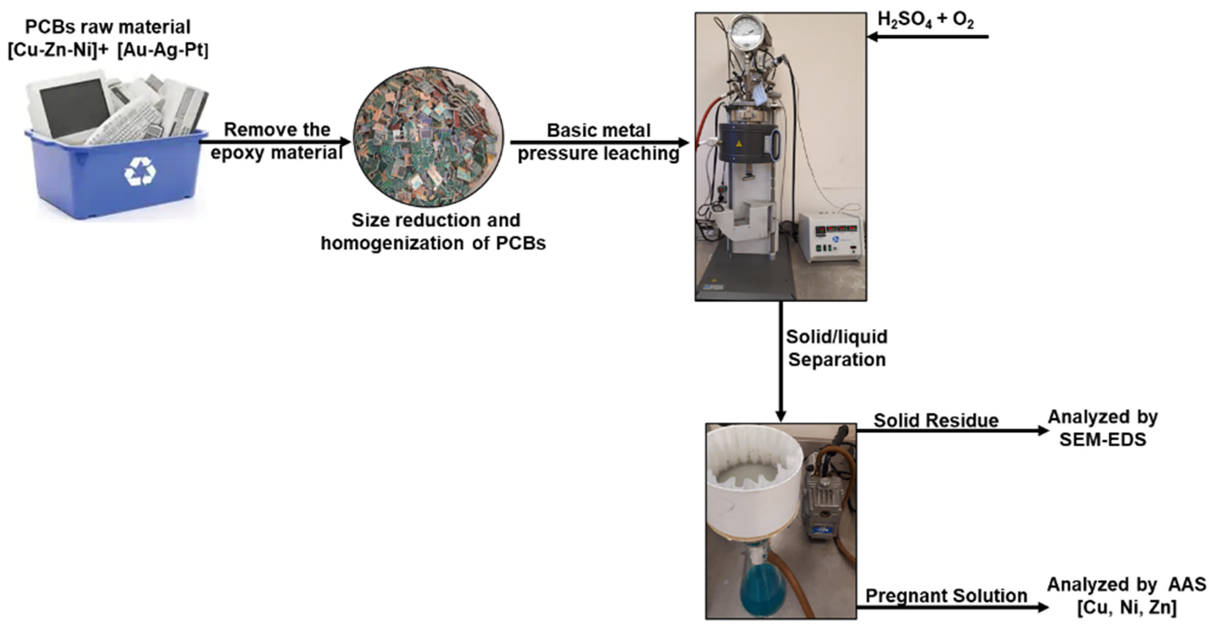
2.2. Methods
3. Results
3.1. Pressure Leaching
3.1.1. Copper
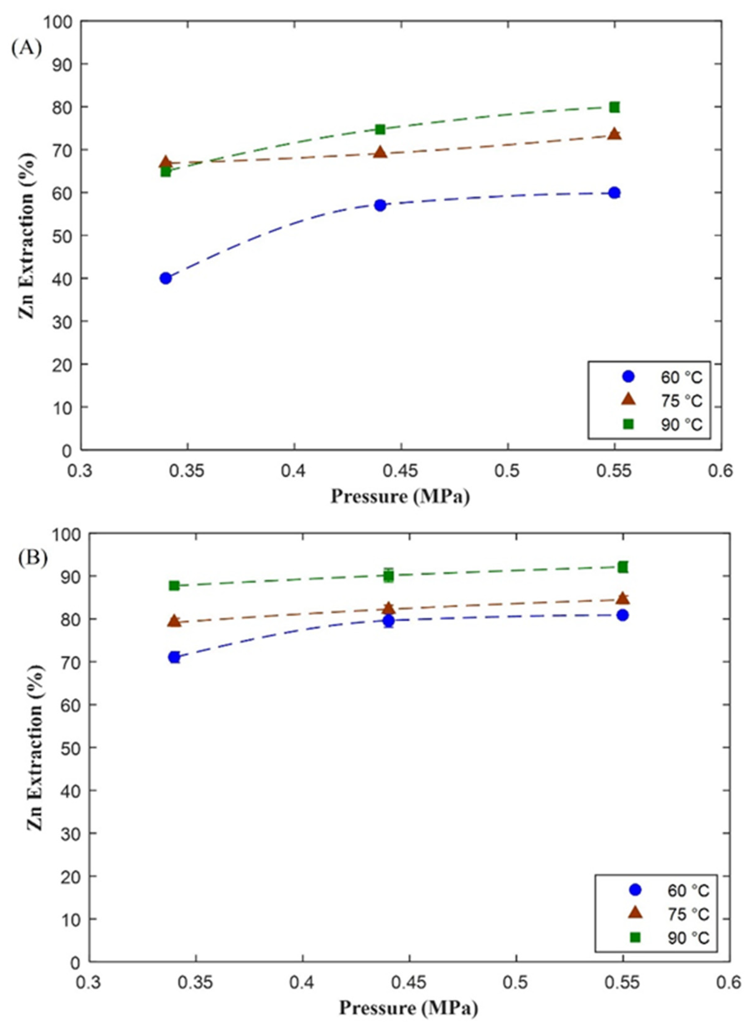
3.1.2. Zinc
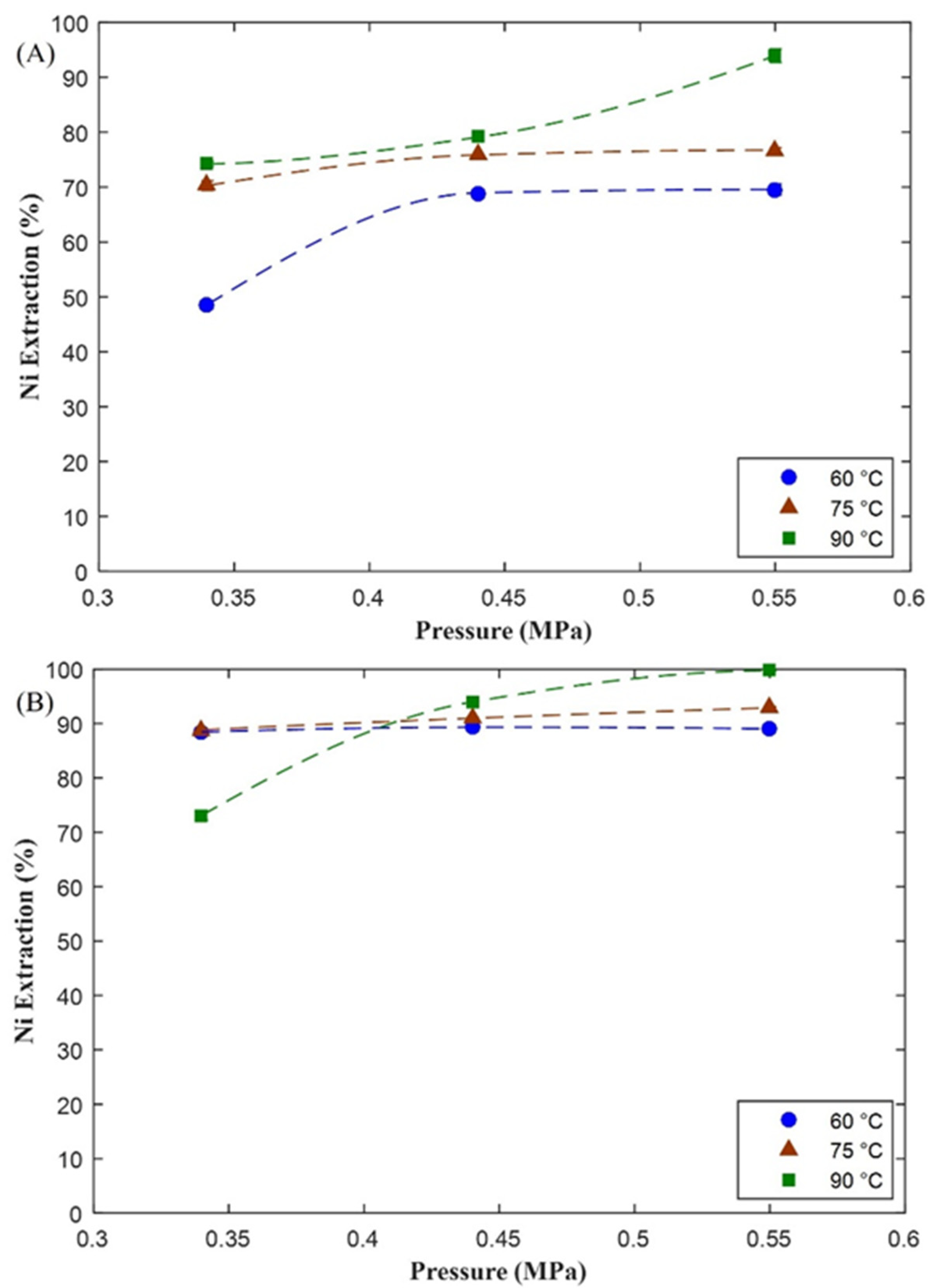
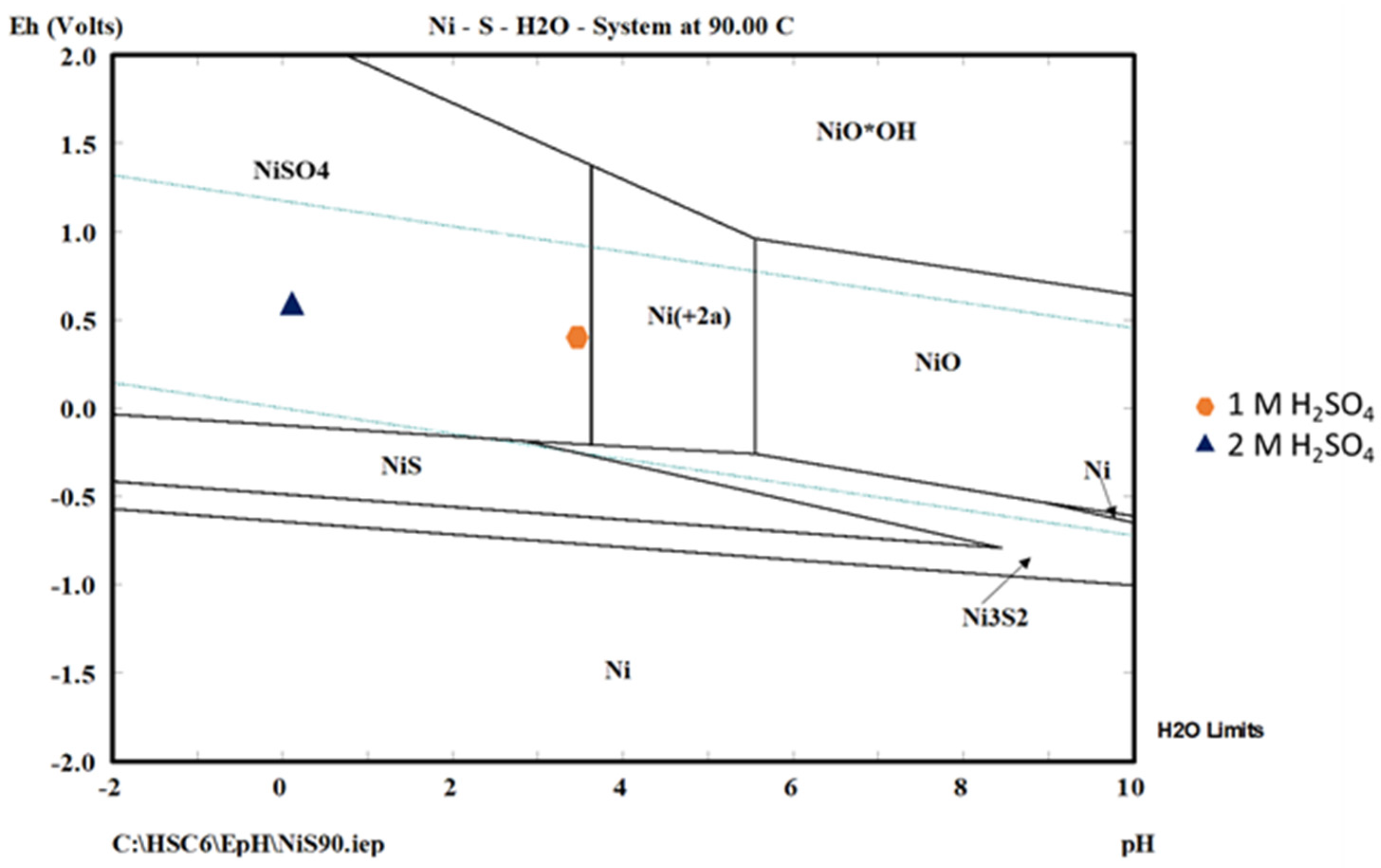
3.1.3. Nickel
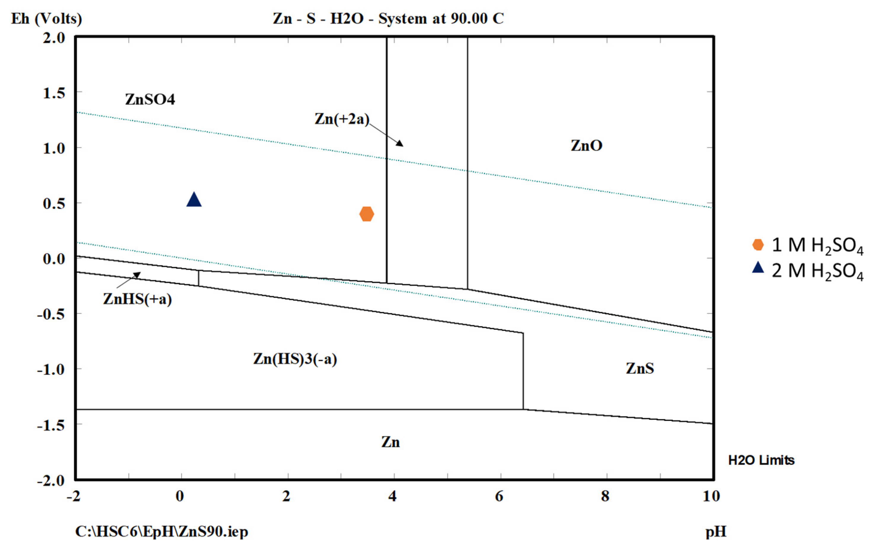
3.2. Thermodynamic Analysis
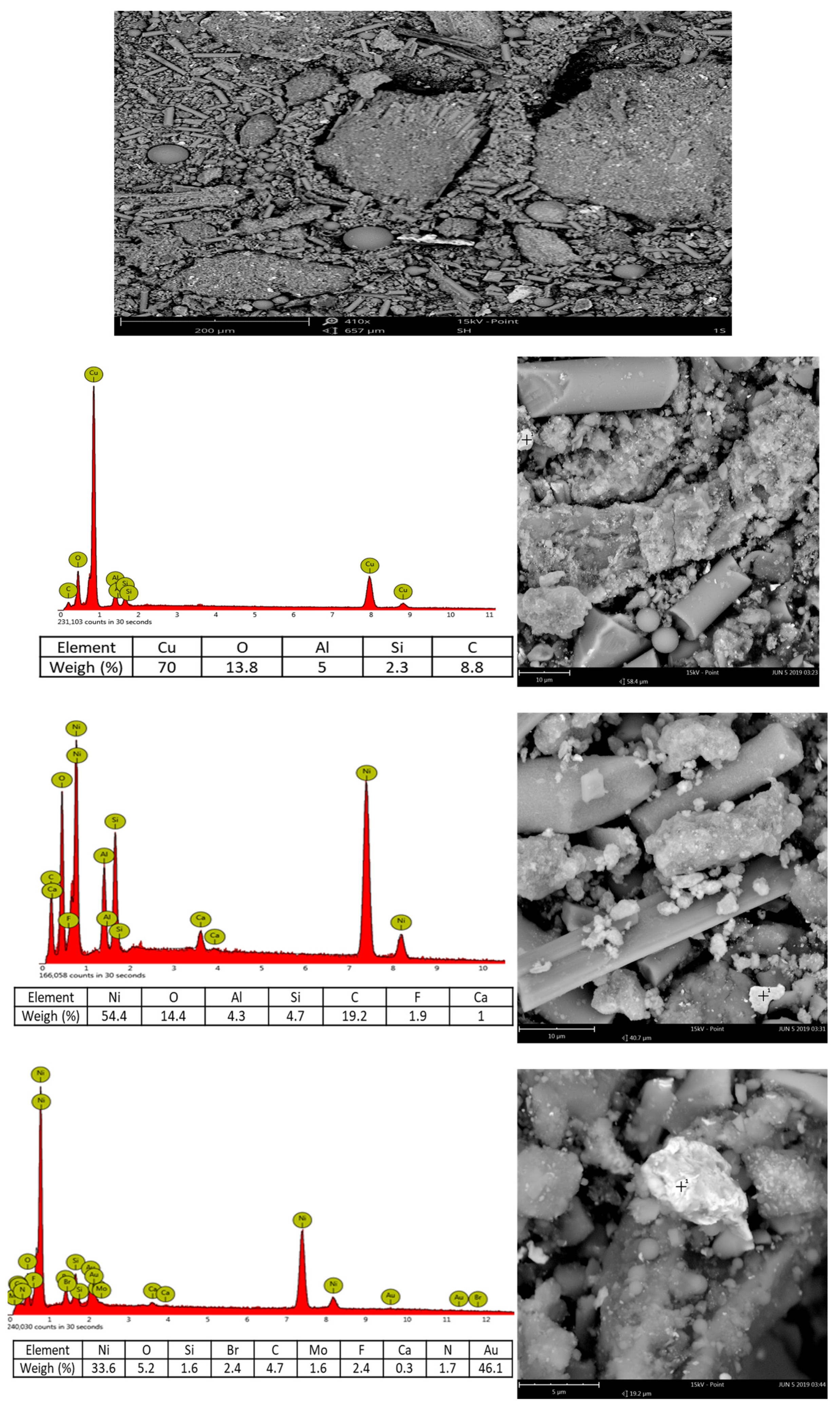
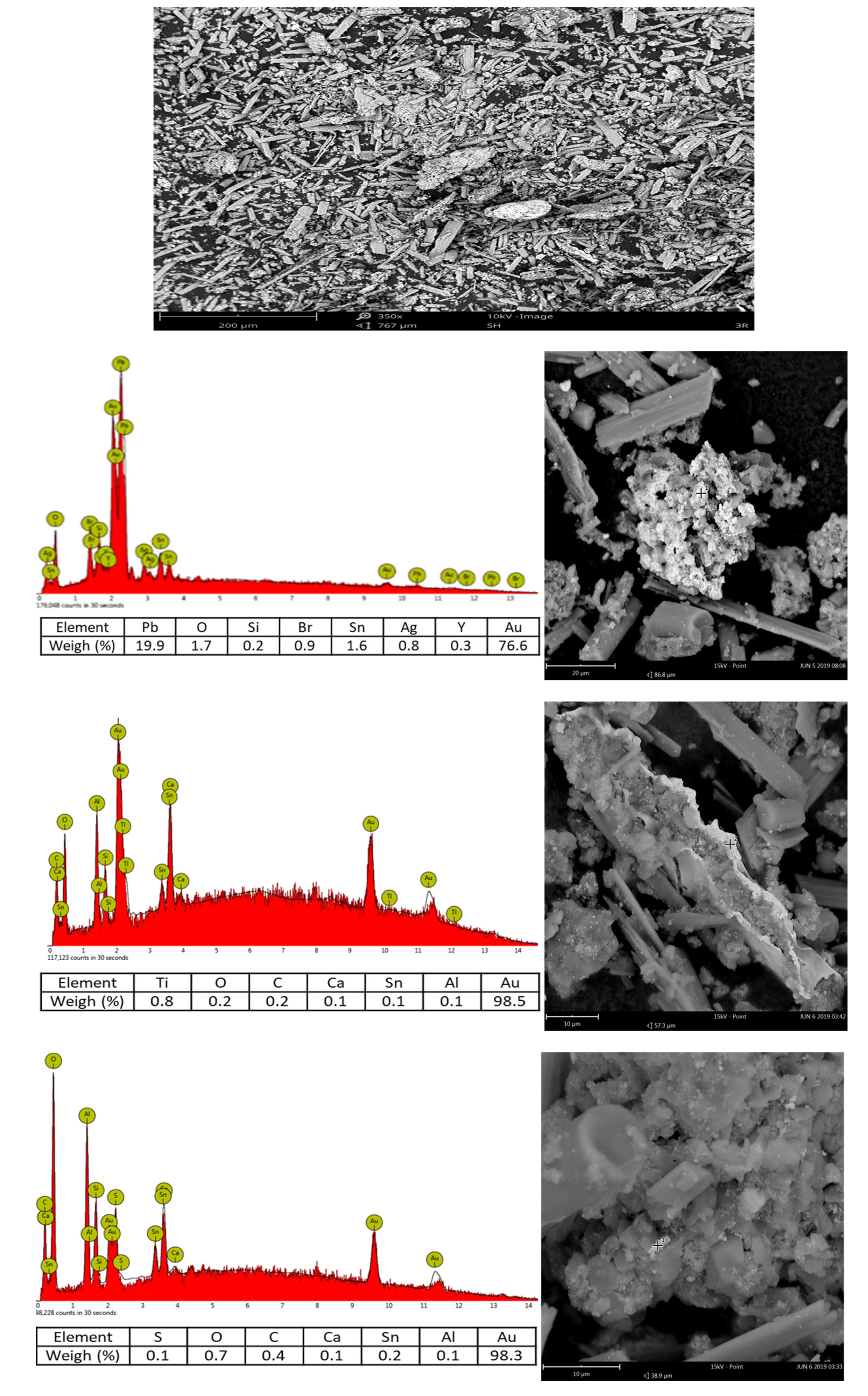
3.3. Study of PCB Material from the Leaching Tests by SEM–EDS
4. Discussion
5. Conclusions
Author Contributions
Funding
Acknowledgments
Conflicts of Interest
References
- Tuncuk, A.; Stazi, V.; Akcil, A.; Yazici, E.Y.; Deveci, H. Aqueous metal recovery techniques from e-scrap: Hydrometallurgy in recycling. Miner. Eng. 2012, 25, 28–37. [Google Scholar] [CrossRef]
- Van Eygen, E.; De Meester, S.; Tran, H.P.; Dewulf, J. Resource savings by urban mining: The case of desktop and laptop computers in Belgium. Resour. Conserv. Recycl. 2016, 107, 53–64. [Google Scholar] [CrossRef] [Green Version]
- Widmer, R.; Oswald-Krapf, H.; Sinha-Khetriwal, D.; Schnellmann, M.; Böni, H. Global perspectives on e-waste. Environ. Impact Assess. Rev. 2005, 25, 436–458. [Google Scholar] [CrossRef]
- Hagelüken, C. Recycling of electronic scrap at Umicore precious metals refining. Acta Metall. Slovaca 2006, 12, 111–120. [Google Scholar]
- Xiu, F.-R.; Zhang, F.-S. Electrokinetic recovery of Cd, Cr, As, Ni, Zn and Mn from waste printed circuit boards: Effect of assisting agents. J. Hazard. Mater. 2009, 170, 191–196. [Google Scholar] [CrossRef] [PubMed]
- Behnamfard, A.; Salarirad, M.M.; Veglio, F. Process development for recovery of copper and precious metals from waste printed circuit boards with emphasize on palladium and gold leaching and precipitation. Waste Manag. 2013, 33, 2354–2363. [Google Scholar] [CrossRef] [PubMed]
- Ylä-Mella, J.; Poikela, K.; Lehtinen, U.; Keiski, R.L.; Pongrácz, E. Implementation of Waste Electrical and Electronic Equipment Directive in Finland: Evaluation of the collection network and challenges of the effective WEEE management. Resour. Conserv. Recycl. 2014, 86, 38–46. [Google Scholar] [CrossRef] [Green Version]
- Hagelüken, C.; Corti, C.W. Recycling of gold from electronics: Cost-effective use through ‘Design for Recycling’. Gold Bull. 2010, 43, 209–220. [Google Scholar] [CrossRef] [Green Version]
- Johnson, J.; Harper, E.M.; Lifset, R.; Graedel, T.E. Dining at the periodic table: Metals concentrations as they relate to recycling. Environ. Sci. Technol. 2007, 41, 1759–1765. [Google Scholar] [CrossRef] [PubMed]
- Mecucci, A.; Scott, K. Leaching and electrochemical recovery of copper, lead and tin from scrap printed circuit boards. J. Chem. Technol. Biotechnol. Int. Res. Process Environ. Clean Technol. 2002, 77, 449–457. [Google Scholar] [CrossRef]
- Castro, L.A.; Martins, A.H. Recovery of tin and copper by recycling of printed circuit boards from obsolete computers. Braz. J. Chem. Eng. 2009, 26, 649–657. [Google Scholar] [CrossRef]
- Yang, H.; Liu, J.; Yang, J. Leaching copper from shredded particles of waste printed circuit boards. J. Hazard. Mater. 2011, 187, 393–400. [Google Scholar] [CrossRef] [PubMed]
- Kumar, M.; Lee, J.-c.; Kim, M.-S.; Jeong, J.; Yoo, K. Leaching of metals from waste printed circuit boards (wpcbs) using sulfuric and nitric acids. Environ. Eng. Manag. J. (EEMJ) 2014, 13, 2601–2607. [Google Scholar]
- Yang, C.; Li, J.; Tan, Q.; Liu, L.; Dong, Q. Green Process of Metal Recycling: Coprocessing Waste Printed Circuit Boards and Spent Tin Stripping Solution. ACS Sustain. Chem. Eng. 2017, 5, 3524–3534. [Google Scholar] [CrossRef]
- Kamberović, Ž.; Ranitovic, M.; Korac, M.; Andjić, Z.; Gajic, N.; Djokic, J.; Jevtic, S. Hydrometallurgical Process for Selective Metals Recovery from Waste-Printed Circuit Boards. Metals 2018, 8, 441. [Google Scholar] [CrossRef] [Green Version]
- Kavousi, M.; Sattari, A.; Alamdari, E.K.; Fatmehsari, D.H. Leaching Studies for Copper and Solder Alloy Recovery from Shredded Particles of Waste Printed Circuit Boards. Metall. Mater. Trans. B 2018, 49, 1464–1470. [Google Scholar] [CrossRef]
- Nekouei, R.K.; Pahlevani, F.; Golmohammadzadeh, R.; Assefi, M.; Rajarao, R.; Chen, Y.-H.; Sahajwalla, V. Recovery of heavy metals from waste printed circuit boards: Statistical optimization of leaching and residue characterization. Environ. Sci. Pollut. Res. 2019, 26, 24417–24429. [Google Scholar] [CrossRef] [PubMed]
- Jadhav, U.; Hocheng, H. Hydrometallurgical recovery of metals from large printed circuit board pieces. Sci. Rep. 2015, 5, 14574. [Google Scholar] [CrossRef] [Green Version]
- Martinez-Ballesteros, G.; Valenzuela-García, J.L.; Gómez-Alvarez, A.; Encinas-Romero, M.A.; Mejía-Zamudio, F.A.; Rosas-Durazo, A.D.; Valenzuela-Frisby, R. Recovery of Ag, Au, and Pt from Printed Circuit Boards by Pressure Leaching. Recycling 2021, 6, 67. [Google Scholar] [CrossRef]
- Schlesinger, M.E.; Sole, K.C.; Davenport, W.G. Extractive Metallurgy of Copper; Elsevier: Amsterdam, The Netherlands, 2011. [Google Scholar]
- Zhou, X.; Guo, J.; Lin, K.; Huang, K.; Deng, J. Leaching characteristics of heavy metals and brominated flame retardants from waste printed circuit boards. J. Hazard. Mater. 2013, 246–247, 96–102. [Google Scholar] [CrossRef] [PubMed]


| Metal | Ag | Au | Pt | Pd | Cu | Zn | Ni | Fe |
|---|---|---|---|---|---|---|---|---|
| Content | 170 (g/t) | 220 (g/t) | 2 (g/t) | 1.2 (g/t) | 13.14% | 0.02% | 4% | 4.9% |
Disclaimer/Publisher’s Note: The statements, opinions and data contained in all publications are solely those of the individual author(s) and contributor(s) and not of MDPI and/or the editor(s). MDPI and/or the editor(s) disclaim responsibility for any injury to people or property resulting from any ideas, methods, instructions or products referred to in the content. |
© 2023 by the authors. Licensee MDPI, Basel, Switzerland. This article is an open access article distributed under the terms and conditions of the Creative Commons Attribution (CC BY) license (https://creativecommons.org/licenses/by/4.0/).
Share and Cite
Martinez-Ballesteros, G.; Valenzuela-Garcia, J.L.; Gomez-Alvarez, A.; Encinas-Romero, M.A.; Mejia-Zamudio, F.A.; Rosas-Durazo, A.d.J. Base Metals Extraction from Printed Circuit Boards by Pressure Acid Leaching. Minerals 2023, 13, 98. https://doi.org/10.3390/min13010098
Martinez-Ballesteros G, Valenzuela-Garcia JL, Gomez-Alvarez A, Encinas-Romero MA, Mejia-Zamudio FA, Rosas-Durazo AdJ. Base Metals Extraction from Printed Circuit Boards by Pressure Acid Leaching. Minerals. 2023; 13(1):98. https://doi.org/10.3390/min13010098
Chicago/Turabian StyleMartinez-Ballesteros, Guadalupe, Jesus Leobardo Valenzuela-Garcia, Agustin Gomez-Alvarez, Martin Antonio Encinas-Romero, Flerida Adriana Mejia-Zamudio, and Aaron de Jesus Rosas-Durazo. 2023. "Base Metals Extraction from Printed Circuit Boards by Pressure Acid Leaching" Minerals 13, no. 1: 98. https://doi.org/10.3390/min13010098