
Research on the Fracture Properties and Mechanism of Carbon Dioxide Blasting Based on Rock-like Materials
1
State Key Laboratory of Safety and Health for Metal Mines, Sinosteel Group Maanshan Mining Research Institute Co., Maanshan 243000, China
2
School of Resources and Environmental Engineering, Wuhan University of Technology, Wuhan 430070, China
*
Author to whom correspondence should be addressed.
Minerals 2023, 13(1), 3; https://doi.org/10.3390/min13010003
Submission received: 18 October 2022
/
Revised: 2 December 2022
/
Accepted: 8 December 2022
/
Published: 20 December 2022
(This article belongs to the Topic Green Low-Carbon Technology for Metalliferous Minerals)
Abstract
:Liquid carbon dioxide blasting technology has a wide range of applications and is characterized by sound fracturing effects, low vibration hazards, and high safety. In order to investigate the characteristics and mechanism of CO2 phase change rock breaking, liquid CO2 blasting tests on rock-like specimens were carried out in this paper. The results show that 130 MPa is the threshold value at which a CO2 blasting system moves from dynamic tensile stress damage to dynamic pressure stress damage. When blasting pressures of 100 MPa and 70 MPa are used, the lumpiness ratio of the fragments does not change much as the strength of the rock changes, so a suitable blasting pressure should be chosen to improve the blasting effect. Under the impact of blast stress and high-pressure gas flow, cracks develop to form a rough failure surface.
1. Introduction
The exploitation of mineral resources has always been one of the primary sources of greenhouse gas emissions [1]. As the global climate crisis continues to intensify, areas such as the reduction and utilization of carbon dioxide are receiving widespread attention [2,3,4]. As an important part of mine production, blasting is also one of the major sources of greenhouse gases in mines, while the hazards of vibration, noise, and flying rocks caused by mine blasting are also problems that need to be addressed urgently by traditional explosives blasting. Carbon dioxide phase change fracturing is a new, green, physical blasting method that enhances the use of carbon dioxide and reduces the number of greenhouse gases produced during blasting. As liquid carbon dioxide fracturing continues to develop, more rock-breaking excavation projects are using this method due to its high safety, ease of operation, and reliable rock-breaking efficiency.
High-pressure gas fracturing technology, also known as the Cardox Tube System, was introduced in 1938 by the British company CARDOX [5] and can be used in large-scale mining, reservoir, and dam construction blasting [6]. Cardox Tube System blasting releases high-pressure carbon dioxide gas, which exerts pressure on the surrounding rock causing a tensile stress field and causing tensile stress damage to the rock to form fissures; when the high pressure gas further impacts the fissures, the fissures begin to develop and expand, eventually cracking and breaking the rock [7].
Since its introduction, CO2 phase change blasting technology has been used extensively in industries such as mining and civil construction. Haidong Chen et al. increased the permeability of the coal seam by using phase change fracturing technology with liquid carbon dioxide. By adopting a reasonable blast hole spacing, the coal seam achieved the desired destruction effect and increased the gas emission flow in the coal seam. This technology greatly increased the permeability of the coal seam and enabled the effective use of gas in the coal mine while also making full use of carbon dioxide gas as an energy source and reducing the emission of greenhouse gases [8,9]. Li Qiyue et al. used liquid carbon dioxide phase change rock-breaking technology for underground pit excavation construction. The method solved the problem of excavating hard rocks in underground pit excavation; no pollution or flying rocks were generated during the blasting process and the blasting vibration was less hazardous, while the blasting effect was good and the blasted rocks were of moderate size and easy to handle [10]. Xie et al. used liquid carbon dioxide phase change technology for blasting excavation of hard rock pile shafts and obtained the relationship between the release pressure, release energy and TNT equivalent of carbon dioxide through field tests and also found that the carbon dioxide vibration wave has the characteristics of short duration, fast decay, and low main frequency, and a proper hollow hole can improve the rock breaking effect when blasting hard rock pile shafts [11].
With the continuous maturation of CO2 phase change fracturing technology, more and more scholars are conducting research on the underlying theory, mechanism of action and effect, and other related aspects of this technology [12,13,14]. Zhang Jiafan et al. studied the CO2 blasting process by numerical simulation and obtained the CO2 blasting stress wave decay law [15]. Zhou Keping and others obtained the pressure variation law through liquid CO2 blasting tests and combined it with the Span–Wagner equation of state to obtain the calculation method for the explosion energy of liquid CO2 blasting systems [16]. Yang et al. calculated the energy of TNT explosions and carbon dioxide explosions through field test research, and the results showed that the TNT equivalent of 1 kg of carbon dioxide is 430 g and 380 g, respectively, which has a good blasting effect in practical engineering applications [17]. Sun Keming et al. conducted CO2 blasting tests on coal bodies with different strengths at different temperatures and found that the minimum pressure of rock breaking was exponentially related to the tensile strength of the material by analyzing the number of fissures, length, and blast response information and that the number of fissures and cumulative length satisfied a logistic function with the blast pressure, while CO2 had a cooling effect during the blasting process [18,19].
In this paper, liquid carbon dioxide blasting tests on rock-like specimens were carried out [20]. The CO2 blast stress variation threshold was investigated. The effect of CO2 fracturing was analyzed by defining the variable lumpiness factor ratio. The mechanism of the rock-breaking action of carbon dioxide blasting systems was studied [21]. It provides a theoretical reference for selecting suitable blasting parameters to improve the fracturing effect of CO2 blasting.
2. Experiment
2.1. Experimental Programme
Two different types of high-strength cement were selected to make test blocks with a block size of 500 mm × 500 mm × 400 mm and a 45 mm diameter blast hole reserved in the middle. The block style is shown in Figure 1 and the block types are shown in Table 1 [22]. Four sets of four specimens with different mechanical properties were produced by controlling the type and proportion of cement. The first three groups of specimens were tested at burst pressures of 70 MPa, 100 MPa, 130 MPa, and 150 MPa, and the fourth group of specimens were all tested at a burst pressure of 70 MPa [23], as shown in Table 1.
2.2. Experimental Preparation
The prepared materials were mixed well in a mixer and poured into prefabricated molds for setting. To ensure the specimens’ homogeneity and avoid air bubbles, a small vibrating rod was used for vibratory pounding, and the models were manually maintained for 28 days after they were made. In order to obtain the basic mechanical parameters of the specimens, cubic specimens with dimensions of 70.7 mm × 70.7 mm × 70.7 mm were produced for physical and mechanical testing, as shown in Figure 2. The cube test blocks were numbered and quantified as shown in Table 2. Longitudinal wave velocity experiments, uniaxial compression experiments, tensile experiments, and variable-angle plate shear experiments were carried out on each group of test blocks [24].
Before conducting the indoor rock mechanics experiments, five to six complete specimens were selected and weighed to obtain the mass and average density of the specimens. The test results and mechanical parameters of the rock experiments are shown in Table 3.
2.3. Experimental Process
The test was carried out in the Phase Change Dynamics Laboratory of Central South University, Changsha, China and was divided into three steps: firstly, the filling of the CO2 blast tube, then the installation and fixing of the blast tube in the specimen, and finally the blasting [25].
(1) In order to meet the different pressure conditions of the blasting test, different directional energy dischargers were selected to control the carbon dioxide charge, which were rated at 70 MPa, 100 MPa, 130 MPa, and 150 MPa [26]. The CO2 bursting tube structure is shown in Figure 3, and the CO2 bursting tube filling mass is shown in Table 4 [27].
(2) The filled blasting tube was inserted into the prefabricated blast hole of the specimen, and to prevent the blasting tube from being thrown upwards during blasting, a weight was loaded on top of the blasting tube to hold it in place. At the same time, in order to prevent safety accidents caused by flying rocks during the blasting test, the blasted specimen was set in a specially designed iron frame.
(3) A liquid carbon dioxide blasting test was conducted by connecting the blasting tube to the wire after installation and by using a multimeter to measure its resistance value to ensure that the wire was correctly connected. The site was cleaned up after the inspection, and we retreated to a safe area and then powered up the blasting tube to detonate.
(4) The number and quality of fragments and the distribution pattern of cracks were counted at the end of the blast.
3. Experimental Results
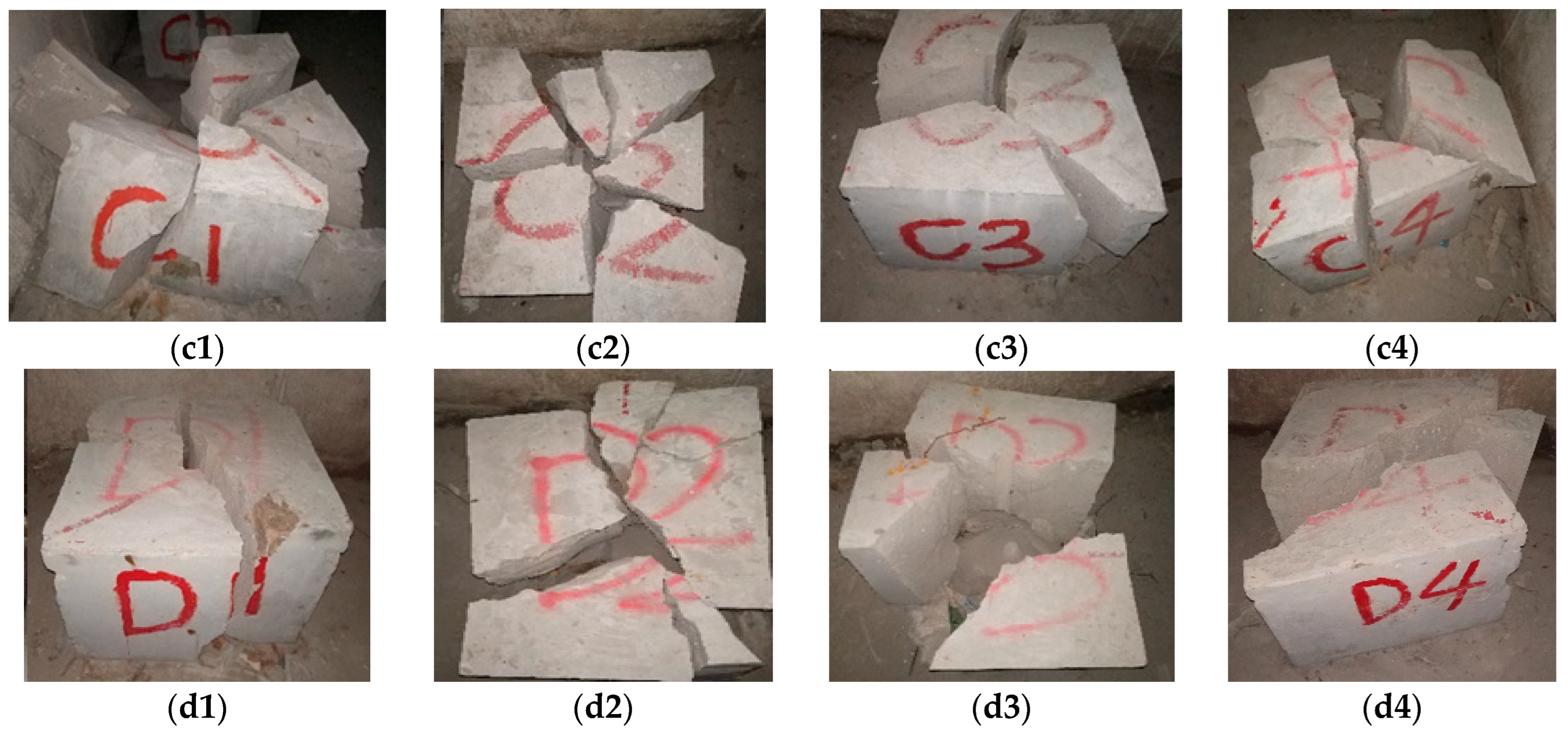
Blasting tests were carried out on specimens with different mechanical properties. Under the action of different blasting pressures, the specimens were blasted into different blocks, and each specimen generated 3–6 main cracks with an approximately linear distribution. The results of the specimen blasting are shown in Figure 4.
From the blast results, the specimen was broken into several major chunks, with a certain number of small fragments at the base of the specimen, and the ring breakage was mainly in the form of tensile damage with some form of shear damage. The main crack in almost every specimen penetrated the entire specimen, and the blast could crack the entire specimen relatively well. The blast hole walls of each specimen were well retained, with smooth surfaces and no impact craters or microcracks [28,29,30].
Analysis of the blasted specimens gives the following characteristics of the CO2 phase change rock-breaking process.
(1) An inverted funnel-shaped conical mass is produced at the bottom of the shell hole of the specimen, while all fragments are in a splitting pattern.
(2) The blasting did not produce crushed pieces and the damaged specimens decomposed mainly into a few larger masses; the blasting only had a cracking effect.
(3) The main cracks produced by blasting are dendritic and extend from the blast hole to the free surface. The number of main cracks is small, typically 2–4, and the main cracks are relatively narrow and can run through the whole or half of the specimen.
(4) The normal phase direction of the damaged surface of the specimen after blasting is perpendicular to the axial direction of the blast hole, and the damaged surface is smooth and intact with no microcracks developing.
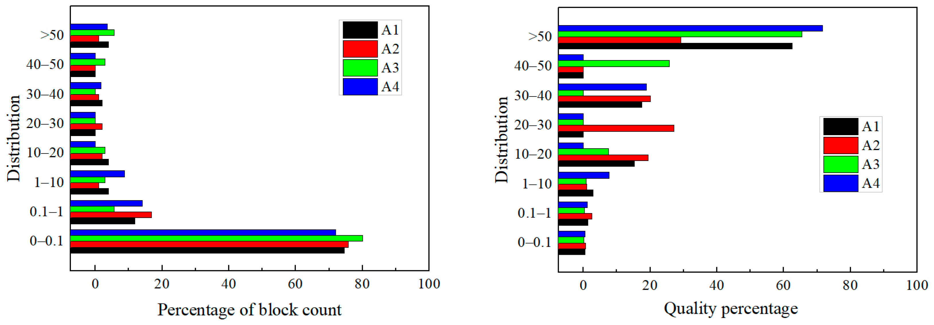
The block size and quantity of the broken blocks after blasting is an important indicators of the blasting effect. Statistical analysis of the number and quality of the blocks after destruction in Group A [31] was carried out, and the results are shown in Figure 5 and Figure 6.
From the analysis it can be concluded that the number and quality of specimen blocks after blasting exhibit the following characteristics.
(1) The number of fragments of small mass in the destroyed specimens is high. The total number of fragments per specimen blasted in Group A was 51, 95, 35, and 57, respectively, with the number of fragments in the mass range of 0 to 0.1 kg being 38, 72, 28, and 41, respectively, representing 74.51%, 75.79%, 80.00%, and 71.93% respectively.
(2) The mass percentages of fragments in the range of 0.1–1 kg and 1–10 kg were evenly distributed, and the numbers of fragments in the range of 10–20 kg, 20–30 kg, 30–40 kg, and 40–50 kg were missing, and the number of fragments with masses over 50 kg was 1 to 2 in each specimen.
(3) From Figure 6, it can be seen that the mass and number of broken pieces were distributed in the opposite pattern, with the larger mass of the pieces occupying the vast majority of the mass of the exploded specimen accounting for 62.5%, 29.2%, 65.45%, and 71.68% of the overall specimen mass, respectively.
(4) The A2 specimen showed a uniform distribution in the number and mass of fragments because the A2 specimen used an explosion-rated pressure of 150 MPa, much greater than the dynamic compressive strength of the specimen, which mainly produced compression damage.
In summary, unlike the fracture zones and fracture zones created during conventional explosive rock-breaking, carbon dioxide blasting is based on the rapid pressure generated by the change in the gas phase. The combined effect of the pressure and high-velocity gas damage the rock, resulting in cracks spreading from the center of the hole in all directions. The main crack breaks the rock into several complete fragments, while the fragments are evenly distributed with no crushing particles, indicating that the CO2 blasting technique fully uses the gas phase change energy and has a good rock-cracking effect.
4. Analysis
4.1. Analysis of the Effect of Blasting Pressure on Blasting Effectiveness
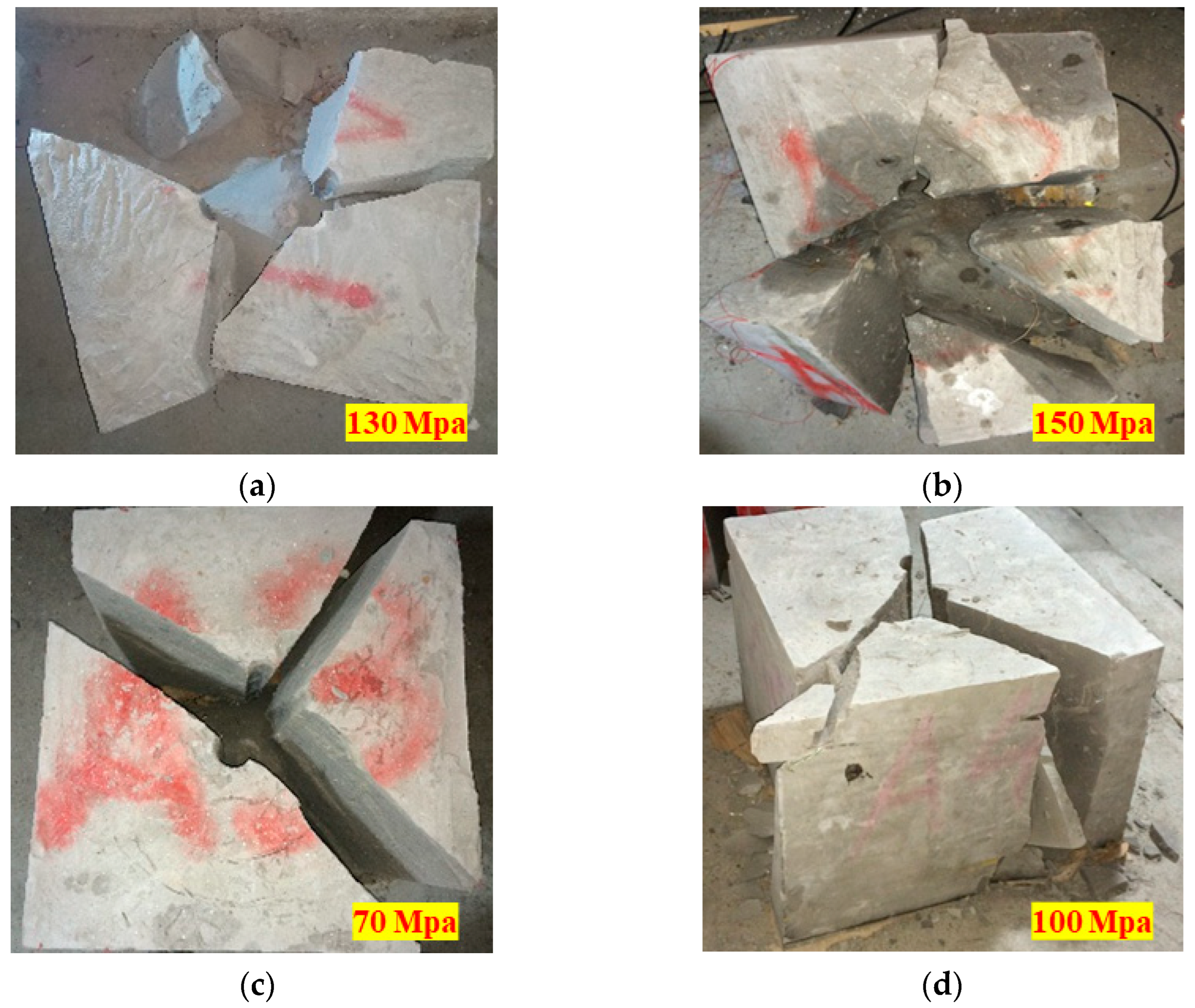
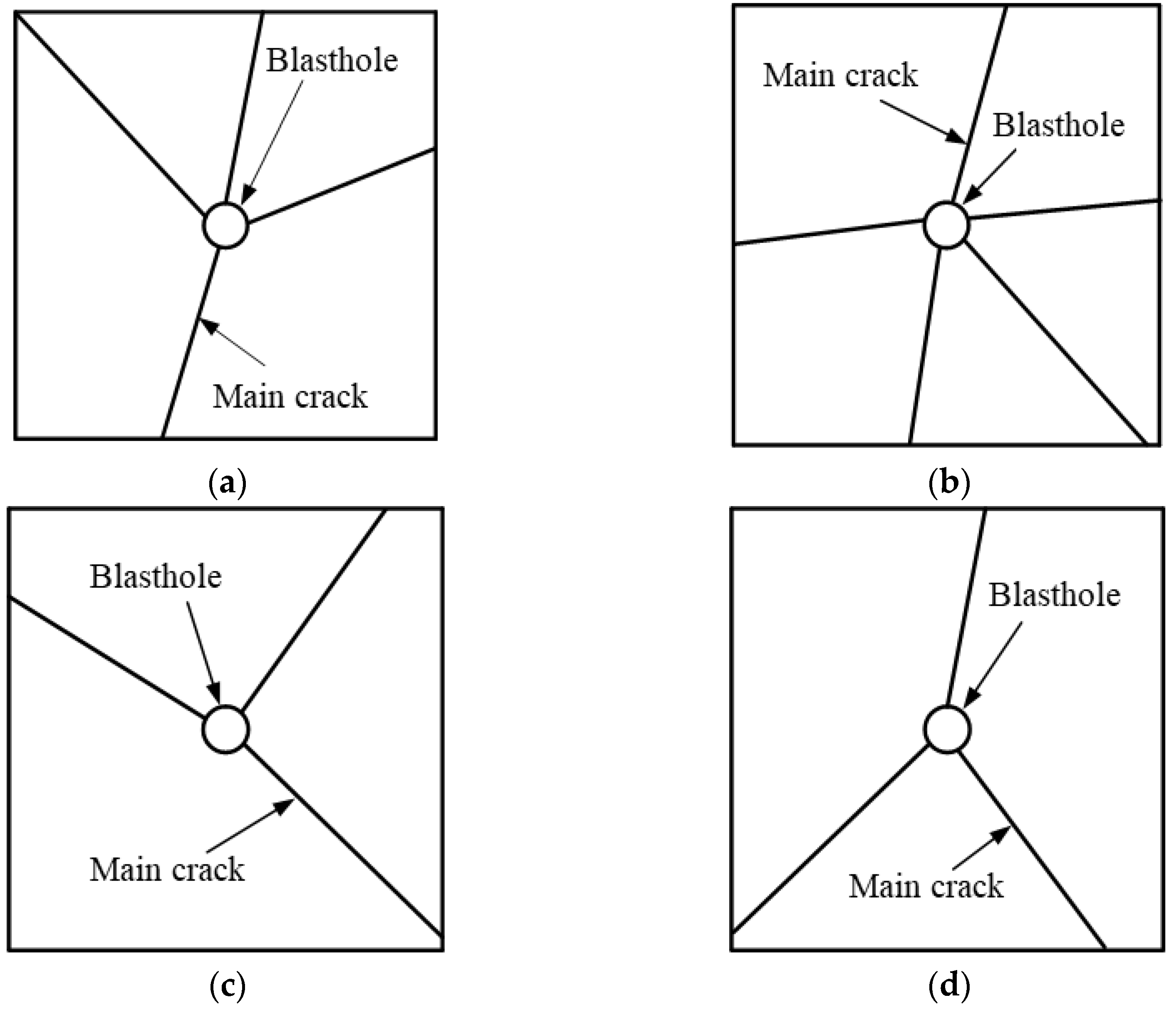
By choosing different rated pressures of energy-discharging discs to burst the specimens, the effect after bursting is shown in Figure 7, and its crack distribution after bursting is shown in Figure 8. It can be seen from the figure that the main crack of the sample presents an approximately linear splitting failure, and the number of cracks and the failure degree of the sample are positively correlated with the bursting pressure.
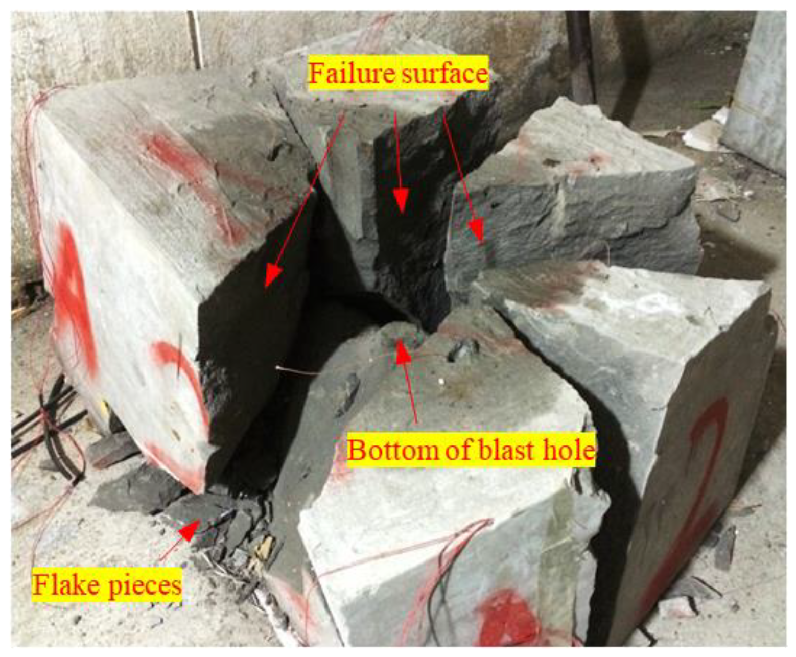
When the blasting pressure is small, from the A3 specimen, after the destruction of the effect of the diagram can be seen, the number of cracks is three, and the specimen mainly shows tension damage. The specimen was destroyed into four blocks, the bottom of which is a conical body block, and the other three blocks were controlled by the main crack formed, while the destruction surface is very smooth. In addition to these four larger blocks, at the junction of the main crack and the bottom of the specimen, there is part of the formation of fragments, but it is not obvious. When the blasting pressure is higher, the result graph of the damaged A2 specimen shows a significant increase in the number of cracks and fragments, with five cracks, while Figure 9 shows that the damaged surface is rougher than the A3 specimen, with flakier fragments appearing at the junction of the main crack and the bottom of the specimen.
The number of main cracks in the blown specimens generally varies after blasting with differently rated blasting pressures of liquid carbon dioxide. The number of main cracks is mainly distributed between 3 and 6. As the rated blasting pressure of liquid carbon dioxide technology continues to increase, the overall trend of the number of main cracks increases, but the increase is small.
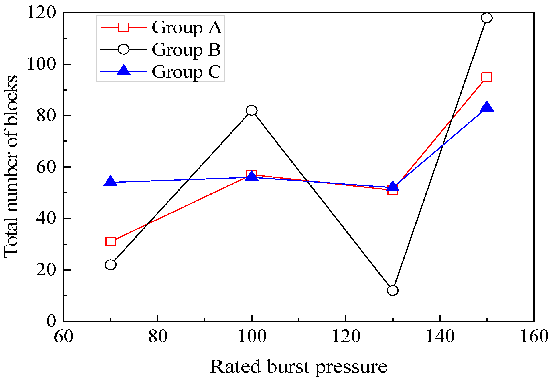
Blasting pressure also influences the distribution of blocks after blasting in liquid carbon dioxide blasting systems. A statistical analysis of the blasting pressure and the number of broken blocks was carried out for three groups of specimens, A, B, and C. As shown in Figure 10, the trend of the total number of broken blocks after damage increased gradually as the blasting pressure increased from 70 MPa to 150 MPa for the three groups. When the bursting pressure is at 130 MPa, the total number of fragments increases less. It even shows a steep downward trend, which is related to the quality of the carbon dioxide charge and the actual yield pressure of the unloading disc. When the bursting pressure reaches 150 MPa above 130 MPa, the number of fragments rapidly increases. In terms of fracture mechanics and impact dynamics, rocks or rock-like features produce different fractures at different loading rates (strain rates), and these fractures, in turn, lead to different numbers and sizes of blocks after damage. In conjunction with the above analysis, it can be concluded that 130 MPa is the threshold value at which a CO2 blasting system moves from dynamic tensile stress damage to dynamic pressure stress damage.
4.2. Analysis of Rock Lumpiness after Carbon Dioxide Blasting
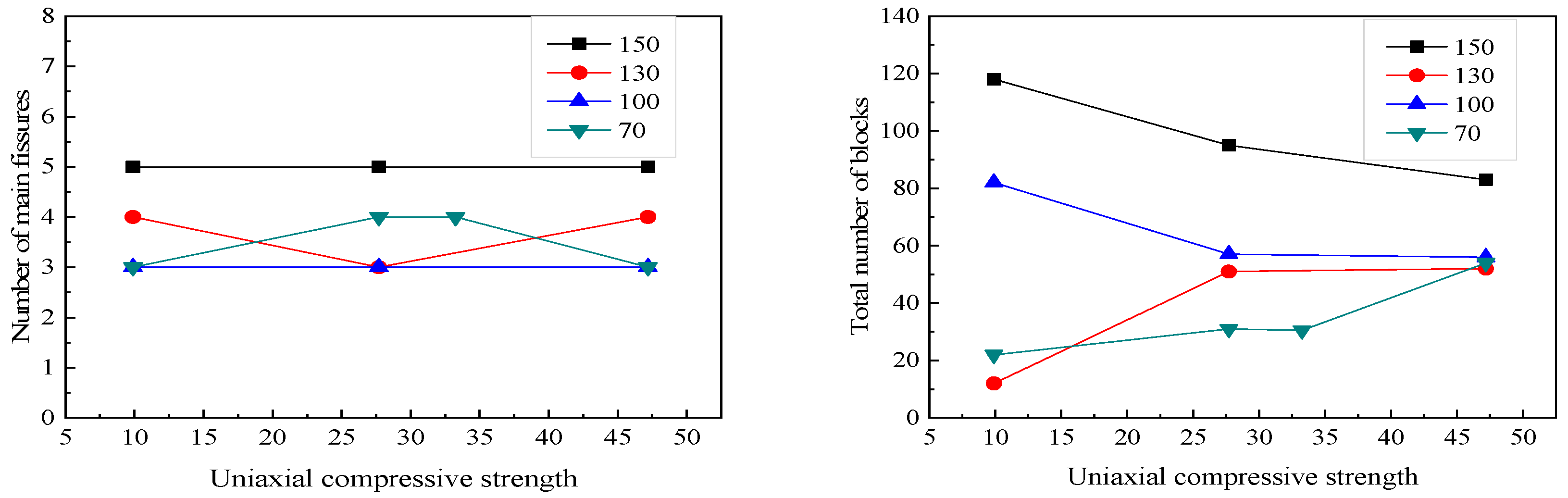
The uniaxial compressive strength and tensile strength of the rock are related to the effect of liquid carbon dioxide blasting, so the uniaxial compressive strength was chosen to characterize the mechanical properties of the rock type. The relationship between the uniaxial compressive strength, the number of main cracks, and the total number of blocks after blasting was obtained through experimental analysis, as shown in Figure 11.
As seen from the figure, the number of main cracks after the damage of test blocks at the same blast pressure is the same or approximately so. Therefore, within the range of compressive strength, the intensity of the specimen has little influence on the number of main cracks. In contrast, the bursting pressure is the main factor affecting the number of main cracks after the damaged blocks.
There are two main trends between the total number of fragments after blasting and the uniaxial compressive strength of the specimens, with the number of fragments after damage decreasing with increasing uniaxial compressive strength at blast pressures of 150 MPa and 100 MPa. At 130 MPa, the number of fragments after damage gradually increases as the uniaxial compressive strength increases. At a bursting pressure of 70 MPa, the overall trend in the number of fragments tends to be similar. As there is a difference between the bursting pressure controlled by the energy discharging disc and the actual pressure, the actual pressure may be close to the bursting pressure of 70 MPa when the bursting pressure of the disc is 100 MPa and 130 MPa, so the bursting effect of the test block after destruction at 150 MPa and 70 MPa was chosen to represent the actual bursting effect. It can be seen from the graph that the higher the bursting pressure, the greater the tendency for compression damage to occur mainly in the test block, and as the uniaxial compressive strength increases, the number of fragments after test block damage gradually decreases; when the bursting pressure is small, the test block mainly undergoes tensile damage, and the number of fragments after test block damage tends to stabilize.
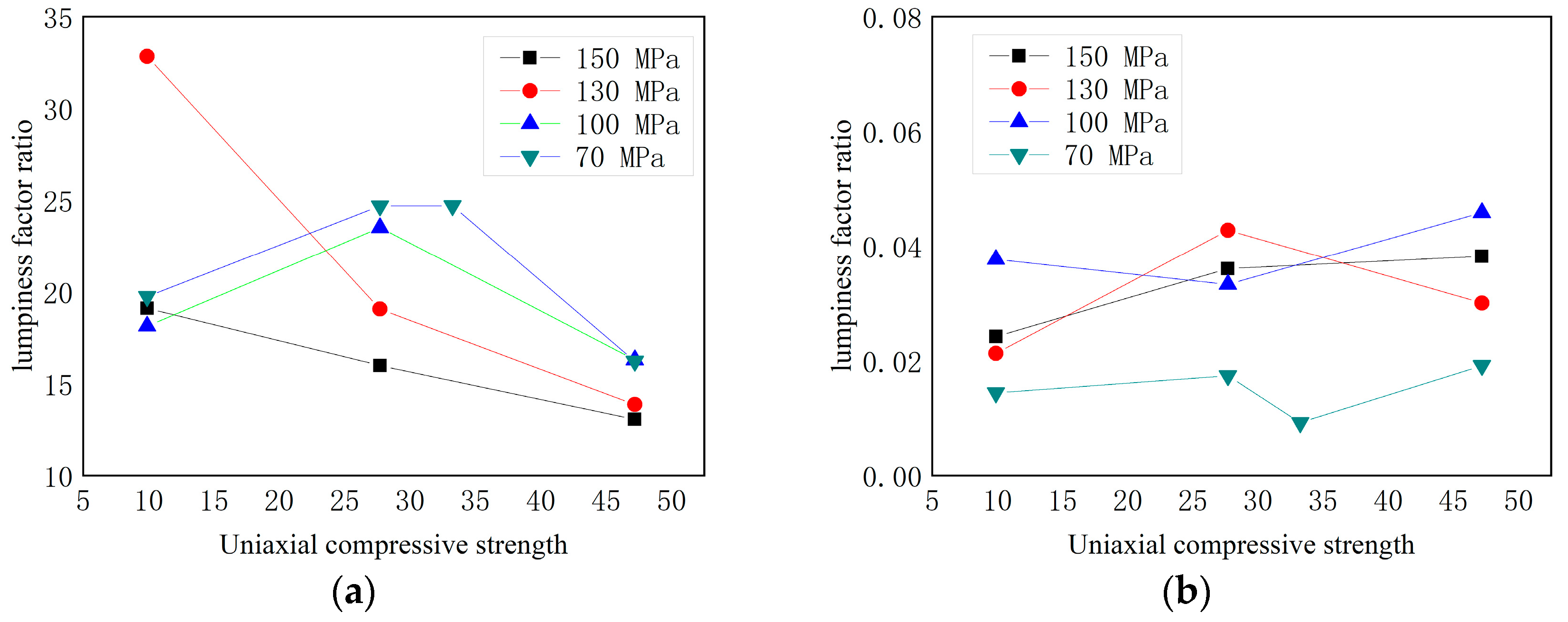
To evaluate the effectiveness of blasting, a variable ‘lumpiness factor ratio’ was defined to represent the size of the fragment. This variable is the ratio of the percentage of mass to the number of fragments after blasting. This parameter is a good indicator of the size of the fragments and ranges from 0 to 100%. Blocks with a mass of less than 5 kg are also defined as small blocks and blocks with a mass greater than 5 kg as large blocks. A larger lumpiness factor ratio indicates a giant and more intact fragment, while the opposite indicates a smaller damaged fragment. A plot of the variation between the fractional lumpiness factor ratio and blast pressure is shown below in Figure 12.
The graph shows that when the bursting pressure is 150 MPa and 130 MPa, the lumpiness factor ratio gradually increases for the larger blocks and decreases for the smaller blocks as the uniaxial compressive strength increases. The results show that the greater the strength of the test block, the smaller the size of the larger block, and the larger the smaller block. At blast pressures of 100 MPa and 70 MPa, as the uniaxial compressive strength increased, the lumpiness factor ratio increased and then decreased for the larger blocks. In comparison, the lumpiness factor ratio decreased and then increased for the smaller blocks, with no significant change in the lumpiness factor ratio for the broken blocks. Therefore, to obtain a good fracturing effect when blasting with CO2, the blasting parameters should be determined according to the actual conditions of the blasted rock.
4.3. Analysis of the Rock-Breaking Mechanism of Carbon Dioxide Blasting Systems
When carbon dioxide blasting, the strength of the initial stress wave near the blast hole far exceeds the dynamic compressive strength of the concrete test block, causing the test block to undergo crushing damage, as shown in Figure 13 [32]. With the stress wave in the process of propagation decay, when the strength of the stress wave σ is less than the dynamic compressive strength of the test block itself σcd, and the stress wave is not enough to directly cause the test block to undergo crushing damage; at this time, the compressive stress wave causes the test block to produce radial displacement, thus generating tensile stress, and under the action of tensile stress, the test block undergoes tensile damage. From the Mises criterion, it is known that when the strength of the blast stress wave σ is less than the dynamic tensile strength σtd of the test block, the stress wave can no longer cause the rock to undergo damage and the rock fracture zone stops developing [33].
The CO2 breaking process is primarily a process of high-pressure gas and gas “wedge action” on the rock, starting with the external impact of the high pressure fluid released from the vent of the liquid CO2 blasting system, where the high pressure CO2 fluid impacts the surrounding rock at maximum pressure, forming an initial crack along the axial direction of the release hole. Here the initial crack acts as a guide, providing a favorable crack development direction for the later gas expansion wedge action. The CO2 fluid released into the confined blast hole then undergoes a phase change to a high-pressure gas, and the blasting process relies primarily on the quasi-static loading of the rock mass by the subsequent high-pressure gas wedging action, which occurs as a result of tensile damage to extend the fracture zone of the liquid CO2 blasting system.
The effect of blasting the specimen shows that the impact and air wedge effect of high-pressure carbon dioxide dominate the rock-breaking process. After blasting, the high-pressure carbon dioxide fluid pressed through the directional shear sheet is released outwards via the outlet at a speed of several hundred meters per second, forming a jet which, while moving forward, also diffuses freely in other directions. The jet velocity and pressure of the CO2 fluid is greatest in the direction of the outlet, decreasing from the axis of the outlet to the sides, and is least in the direction of the vertical outlet. Under the action of a high-pressure CO2 fluid jet impact, two forms of damage to the specimen occur, either by the formation of an impact crater or by tension damage. The reason why impact craters appear in the specimen pore wall is because the specimen itself is a porous medium with a large number of internal pores, microcracks, and other defects developed. Under the impact load of high-speed CO2, these defects further develop to form fragments and are washed away by the CO2, thus forming impact craters. In addition, under the impact of high velocity carbon dioxide, the pressure propagates to the outside of the specimen in the form of stress waves. As the strength of the stress waves is less than the dynamic compressive strength of the specimen, the specimen is not crushed and damaged, but tensile stresses are derived, causing tensile damage to the specimen as well as crack development, at which point the carbon dioxide gas rapidly intrudes into these microcracks, causing stress concentrations at the crack tips and causing further development of these microcracks to form a smooth damage surface [20].
In addition to this, the structure of the liquid carbon dioxide blasting tube itself directly leads to uneven stresses on the blast hole wall, with the maximum compressive stress on the rock in the direction of the outlet hole and the minimum compressive stress in the direction of the vertical outlet hole; the initial state of stress on the blast hole wall is shown in Figure 14 [34]. The uneven force on the hole wall leads to the formation of shear stress inside the specimen, causing shear damage to the specimen, resulting in shear cracks, and carbon dioxide also enters these cracks, under the combined effect of shear action and high-pressure carbon dioxide gas, forming a rough shear-damaged surface.
5. Conclusions
In this paper, the crack distribution morphology of the specimens after liquid carbon dioxide blasting was analyzed. The number and mass distribution of fragments under different blasting pressures were counted. The variable ‘lumpiness factor ratio’ was defined to describe the lumpiness of the fragments after blasting. The mechanism of rock-breaking action of the CO2 blasting system was analyzed. The main conclusions are shown below.
(1) According to the statistical analysis, the number of fragments of 0~0.1 kg in the specimens after CO2 blasting was high, accounting for 74.51%, 75.79%, 80.00%, and 71.93%, respectively. The bulk masses occupied most of the weight of the specimens with 62.5%, 29.2%, 65.45%, and 71.68%, respectively. The quality of the fragments after blasting is inversely related to the quantity. The results show that CO2 blasting has a good rock-fracturing effect.
(2) The main crack of the specimen after blasting was damaged by splitting in a linear pattern extending from the center of the blast hole to the surrounding area, and the number of cracks was 3~6. There was a small increase in the number of cracks as the blast pressure increased, and 130 MPa is the threshold value at which a CO2 blasting system moves from dynamic tensile stress damage to dynamic pressure stress damage.
(3) When the blasting pressure is 100 MPa and 70 MPa, the lumpiness factor ratio of the fragments does not increase or decrease gradually but increases and then decreases. Therefore, in the actual CO2 blasting, to obtain the ideal fracturing effect, the blasting parameters should be selected according to the compressive strength of the rock.
(4) During the initial stress wave propagation, the specimen’s dynamic compressive strength is less than the range of the stress wave cracking damage that occurs, forming small-size fragments. With the decay of the stress wave, the specimen undergoes tensile damage and cracks into large fragments. Since the stress distribution of the specimen is not uniform, the rock fractures are further developed under stress and high-velocity gas, forming a rough shear-damaged surface.
Author Contributions
Conceptualization, J.C.; methodology, J.C.; software, L.S.; validation, B.D. and H.L.; formal analysis, J.C. and Z.L.; investigation, X.Z. and L.S.; resources, B.D., H.L. and B.K.; data curation, X.Z.; writing—original draft preparation, Z.L. and X.Z.; writing—review and editing, J.C. and B.K.; visualization, Z.L.; supervision, B.D. and H.L.; project administration, L.S.; funding acquisition, L.S. All authors have read and agreed to the published version of the manuscript.
Funding
This research was supported by the State Key Laboratory of Safety and Health for Metal Mines (No. 2019-JSKSSYS-03) and the National Key R&D Program (No. 2020YFC1909101; No. 2020YFC1909801).
Data Availability Statement
Not applicable.
Conflicts of Interest
The authors declare no conflict of interest.
References
- Wang, G.; Zhou, J. Multiobjective Optimization of Carbon Emission Reduction Responsibility Allocation in the Open-Pit Mine Production Process against the Background of Peak Carbon Dioxide Emissions. Sustainability 2022, 14, 9514. [Google Scholar] [CrossRef]
- Cao, Z.; Deng, J.; Zhou, S.; He, Y. Research on the feasibility of compressed carbon dioxide energy storage system with underground sequestration in antiquated mine goaf. Energy Convers. Manag. 2020, 211, 112788. [Google Scholar] [CrossRef]
- Chen, H.; Wang, Z.; Chen, X.; Chen, X.; Wang, L. Increasing permeability of coal seams using the phase energy of liquid carbon dioxide. J. CO2 Util. 2017, 19, 112–119. [Google Scholar] [CrossRef]
- Detheridge, A.; Hosking, L.J.; Thomas, H.R.; Sarhosis, V.; Gwynn-Jones, D.; Scullion, J. Deep seam and minesoil carbon sequestration potential of the South Wales Coalfield, UK. J Env. Manag. 2019, 248, 109325. [Google Scholar] [CrossRef]
- Singh, S.P. Non-Explosive Applications of the PCF Concept for Underground Excavation. Tunn. Undergr. Space Technol. 1998, 13, 305–311. [Google Scholar] [CrossRef]
- Kang, J.; Zhou, F.; Qiang, Z.; Zhu, S. Evaluation of gas drainage and coal permeability improvement with liquid CO2 gasification blasting. Adv. Mech. Eng. 2018, 10, 1687814018768578. [Google Scholar] [CrossRef] [Green Version]
- Fan, Y.; Qin, B.; Zhou, Q.; Shi, Q.; Ma, D.; Wu, J. Liquid CO2 phase transition fracturing technology and its application in enhancing gas drainage of coal mines. Adsorpt. Sci. Technol. 2020, 38, 393–412. [Google Scholar] [CrossRef]
- Chen, H.-D.; Wang, Z.-F.; Qi, L.-L.; An, F.-H. Effect of liquid carbon dioxide phase change fracturing technology on gas drainage. Arab. J. Geosci. 2017, 10, 314. [Google Scholar] [CrossRef]
- Hu, X.; Zhang, R.; Zhang, B.; Zhang, X.; Zhang, L.; Yang, Y.; Yan, F.; Li, X. A Study on the Factors Influencing Coal Fracturing Range Caused by Liquid Carbon Dioxide Phase Transition. Geofluids 2022, 2022, 4754764. [Google Scholar] [CrossRef]
- Li, Q.; Liu, X.; Wu, Z.; Xie, X. Application of liquid CO2 phase change rock breaking technology in metro foundation pit excavation. J. Railw. Sci. Eng. 2018, 15, 163–169. [Google Scholar] [CrossRef]
- Xie, X.; Li, X.; Li, Q.; Ma, H.; Liu, X. Liquid CO2 phase-transforming rock fracturing technology in pile-well excavation. J. Cent. South Univ. 2018, 49, 2031–2038. [Google Scholar]
- Cao, Y.; Zhang, J.; Zhai, H.; Fu, G.; Tian, L.; Liu, S. CO2 gas fracturing: A novel reservoir stimulation technology in low permeability gassy coal seams. Fuel 2017, 203, 197–207. [Google Scholar] [CrossRef]
- He, W.; He, F.; Zhang, K.; Zhao, Y.; Zhu, H. Increasing Permeability of Coal Seam and Improving Gas Drainage Using a Liquid Carbon Dioxide Phase Transition Explosive Technology. Adv. Civ. Eng. 2018, 2018, 3976505. [Google Scholar] [CrossRef] [Green Version]
- Zhang, X.; Lu, Y.; Tang, J.; Zhou, Z.; Liao, Y. Experimental study on fracture initiation and propagation in shale using supercritical carbon dioxide fracturing. Fuel 2017, 190, 370–378. [Google Scholar] [CrossRef]
- Zhang, J.; Gao, Z.; Cheng, S.; Zhang, H. Parameters determination of coal-rock HJC model and research on blasting characteristics by liquid CO2. Chin. J. Rock Mech. Eng. 2021, 40, 2633–2642. [Google Scholar] [CrossRef]
- Zhou, K.; Ke, B.; Li, J.; Zhang, Y.; Cheng, L. Pressure Dynamic Response and Explosion Energy of Liquid Carbon Dioxide Blasting System. Blasting 2017, 34, 7–13. [Google Scholar]
- Yang, X.; Wen, G.; Sun, H.; Li, X.; Lu, T.; Dai, L.; Cao, J.; Li, L. Environmentally friendly techniques for high gas content thick coal seam stimulation─multi-discharge CO2 fracturing system. J. Nat. Gas Sci. Eng. 2019, 61, 71–82. [Google Scholar] [CrossRef]
- Sun, K.; Xin, L.; Zhang, S.; Li, T.; Wu, D. Experimental study on laws of crack caused by gas burst of supercritical carbon dioxide. J. Saf. Sci. Technol. 2016, 12, 27–31. [Google Scholar]
- Sun, K.; Zhou, H.; Xie, m.; Ji, H.; Chen, S. Experimental study on variation rules of impact stress for the supercritical CO2 explosion nozzle at different temperatures and pressures. J. Exp. Mech. 2020, 35, 695–701. [Google Scholar]
- Zhang, Y.; Deng, J.; Ke, B.; Deng, H.; Li, J. Experimental Study on Explosion Pressure and Rock Breaking Characteristics under Liquid Carbon Dioxide Blasting. Adv. Civ. Eng. 2018, 2018, 7840125. [Google Scholar] [CrossRef]
- Zhou, S.; Luo, X.; Jiang, N.; Zhang, Z.; Yao, Y. A review on fracturing technique with carbon dioxide phase transition. Chinese Journal of Engineering 2021, 43, 883–893. [Google Scholar] [CrossRef]
- Liu, X.W.; Liu, Q.S.; Huang, S.B.; Wei, L.; Lei, G.F. Fracture Propagation Characteristic and Micromechanism of Rock-Like Specimens under Uniaxial and Biaxial Compression. Shock Vib. 2016, 2016, 6018291. [Google Scholar] [CrossRef] [Green Version]
- Ge, J.J.; Xu, Y. A Method for Making Transparent Hard Rock-Like Material and Its Application. Adv. Mater. Sci. Eng. 2019, 2019, 1274171. [Google Scholar] [CrossRef] [Green Version]
- Liu, D.Q.; He, M.C.; Cai, M. A damage model for modeling the complete stress-strain relations of brittle rocks under uniaxial compression. Int. J. Damage Mech. 2018, 27, 1000–1019. [Google Scholar] [CrossRef]
- Gao, F.; Tang, L.; Zhou, K.; Zhang, Y.; Ke, B. Mechanism Analysis of Liquid Carbon Dioxide Phase Transition for Fracturing Rock Masses. Energies 2018, 11, 2909. [Google Scholar] [CrossRef] [Green Version]
- Zhang, Y.; Deng, J.; Deng, H.; Ke, B. Peridynamics simulation of rock fracturing under liquid carbon dioxide blasting. Int. J. Damage Mech. 2018, 28, 1038–1052. [Google Scholar] [CrossRef]
- Xia, J.; Dou, B.; Tian, H.; Zheng, J.; Cui, G.; Kashif, M. Research on Initiation of Carbon Dioxide Fracturing Pipe Using the Liquid Carbon Dioxide Phase-Transition Blasting Technology. Energies 2021, 14, 521. [Google Scholar] [CrossRef]
- Gue, P.F.; Ye, K.K.; Tao, Z.G.; Liang, H.D.; Yuan, Y.D. Experimental Study on Key Parameters of Bidirectional Cumulative Tensile Blasting with Coal-Containing Composite Roof. Ksce J. Civ. Eng. 2021, 25, 1718–1731. [Google Scholar] [CrossRef]
- Wang, B.; Li, H.B.; Shao, Z.S.; Chen, S.A.; Li, X.F. Investigating the mechanism of rock fracturing induced by high-pressure gas blasting with a hybrid continuum-discontinuum method. Comput. Geotech. 2021, 140, 104445. [Google Scholar] [CrossRef]
- Yang, R.S.; Ding, C.X.; Yang, L.Y.; Lei, Z.; Zhang, Z.R.; Wang, Y.B. Visualizing the blast-induced stress wave and blasting gas action effects using digital image correlation. Int. J. Rock Mech. Min. Sci. 2018, 112, 47–54. [Google Scholar] [CrossRef]
- Jug, J.; Strelec, S.; Gazdek, M.; Kavur, B. Fragment Size Distribution of Blasted Rock Mass. In Proceedings of the 3rd World Multidisciplinary Earth Sciences Symposium (WMESS), Prague, Czech Republic, 11–15 September 2017. [Google Scholar]
- Ke, B.; Zhou, K.; Ren, G.; Shi, J.; Zhang, Y. Positive Phase Pressure Function and Pressure Attenuation Characteristic of a Liquid Carbon Dioxide Blasting System. Energies 2019, 12, 4134. [Google Scholar] [CrossRef] [Green Version]
- Wang, Y. The Rock-Breaking Mechanism of Directional Fracture Blast Using an Irregular Shape Cartridge and Its Field Application. J. Test. Eval. 2019, 47, 1551–1568. [Google Scholar] [CrossRef]
- Jia, J.; Wang, D.; Li, B.; Tian, X. Study of the influencing factors of the liquid CO2 phase change fracturing effect in coal seams. PLoS ONE 2021, 16, e0254996. [Google Scholar] [CrossRef] [PubMed]
Figure 1.
Concrete test block shell hole layout.

Figure 2.
Cube test blocks.

Figure 3.
Schematic diagram of the CO2 blasting tube structure.

Figure 4.
Blasting results. (a1–a4) Blasting results of specimens A-1 to A-4; (b1–b4) Blasting results of specimens B-1 to B-4; (c1–c4) Blasting results of specimens C-1 to C-4; (d1–d4) Blasting results of specimens D-1 to D-4.
Figure 4.
Blasting results. (a1–a4) Blasting results of specimens A-1 to A-4; (b1–b4) Blasting results of specimens B-1 to B-4; (c1–c4) Blasting results of specimens C-1 to C-4; (d1–d4) Blasting results of specimens D-1 to D-4.


Figure 5.
Distribution of block numbers and block masses.

Figure 6.
Distribution of number of blocks and percentage of block mass.

Figure 7.
Graph of blast results for Group A specimens. (a) A-1 specimen after blasting; (b) A-2 specimen after blasting; (c) A-3 specimen after blasting; (d) A-4 specimen after blasting.
Figure 7.
Graph of blast results for Group A specimens. (a) A-1 specimen after blasting; (b) A-2 specimen after blasting; (c) A-3 specimen after blasting; (d) A-4 specimen after blasting.

Figure 8.
Shape of the main fracture and its distribution in Group A specimens. (a) Crack distribution of A-1 specimen; (b) Crack distribution of A-2 specimen; (c) Crack distribution of A-3 specimen; (d) Crack distribution of A-4 specimen.
Figure 8.
Shape of the main fracture and its distribution in Group A specimens. (a) Crack distribution of A-1 specimen; (b) Crack distribution of A-2 specimen; (c) Crack distribution of A-3 specimen; (d) Crack distribution of A-4 specimen.

Figure 9.
Conical and flaky masses formed after blasting of specimen A2.

Figure 10.
Variation in the total block count at different blast pressure ratings.

Figure 11.
Relationship between uniaxial compressive strength and blasting effectiveness.

Figure 12.
Relationship between lumpiness factor ratio and uniaxial compressive strength. (a) Lumpiness factor for large blocks. (b) Lumpiness factor for small blocks.
Figure 12.
Relationship between lumpiness factor ratio and uniaxial compressive strength. (a) Lumpiness factor for large blocks. (b) Lumpiness factor for small blocks.

Figure 13.
Stress wave intensity decay pattern. σ is Stress wave strength; r is the distance to the center of the blast hole; σcd is the dynamic compressive strength of the test block; σtd is the dynamic tensile strength of the test block; r0 is the radius of the blast hole.
Figure 13.
Stress wave intensity decay pattern. σ is Stress wave strength; r is the distance to the center of the blast hole; σcd is the dynamic compressive strength of the test block; σtd is the dynamic tensile strength of the test block; r0 is the radius of the blast hole.

Figure 14.
Schematic diagram of the initial stresses on the blast hole wall.


Table 1.
Types of test blocks.
| Group | No. | Proportioning | Bursting Pressure | Group | No. | Proportioning | Bursting Pressure |
|---|---|---|---|---|---|---|---|
| A | A-1 | 325# silicate cement: river sand: water = 1:1:0.5 | 130 | C | C-1 | 425# silicate cement: river sand: water = 1:1:0.5 | 150 |
| A-2 | 325# silicate cement: river sand: water = 1:1:0.5 | 150 | C-2 | 425# silicate cement: river sand: water = 1:1:0.5 | 130 | ||
| A-3 | 325# silicate cement: river sand: water = 1:1:0.5 | 70 | C-3 | 425# silicate cement: river sand: water = 1:1:0.5 | 100 | ||
| A-4 | 325# silicate cement: river sand: water = 1:1:0.5 | 100 | C-4 | 425# silicate cement: river sand: water = 1:1:0.5 | 70 | ||
| B | B-1 | 325# silicate cement: river sand: water = 1:2:0.5 | 150 | D | D-1 | 425# silicate cement: river sand: water = 1:2:0.5 | 70 |
| B-2 | 325# silicate cement: river sand: water = 1:2:0.5 | 130 | D-2 | 425# silicate cement: river sand: water = 1:2:0.5 | 70 | ||
| B-3 | 325# silicate cement: river sand: water = 1:2:0.5 | 100 | D-3 | 425# silicate cement: river sand: water = 1:2:0.5 | 70 | ||
| B-4 | 325# silicate cement: river sand: water = 1:2:0.5 | 70 | D-4 | 425# silicate cement: river sand: water = 1:2:0.5 | 70 |
Table 2.
Types of cubic test blocks.
| Group | Proportioning | Quantity |
|---|---|---|
| E | 325# silicate cement: river sand: water = 1:1:0.5 | 9 |
| J | 325# silicate cement: river sand: water = 1:2:0.5 | 9 |
| N | 425# silicate cement: river sand: water = 1:1:0.5 | 9 |
| T | 425# silicate cement: river sand: water = 1:2:0.5 | 9 |
Table 3.
Mechanical parameters.
| Specimen Group | Density (g/cm3) | Longitudinal Wave Speed (m/s) | Uniaxial Compressive Strength (MPa) | Poisson’s Ratio | Elasticity Modulus (GPa) | Uniaxial Tensile Strength (MPa) | Internal Cohesion (MPa) | Angle of Internal Friction (°) |
|---|---|---|---|---|---|---|---|---|
| A | 1.812 | 3235.71 | 27.70 | 0.234 | 2.01 | 2.47 | 7.02 | 37.75 |
| B | 1.878 | 2666.06 | 9.89 | 0.299 | 0.99 | 1.17 | 2.82 | 37.29 |
| C | 1.986 | 3724.99 | 47.19 | 0.243 | 4.69 | 3.41 | 9.06 | 39.69 |
| D | 2.057 | 3922.84 | 33.25 | 0.226 | 2.21 | 3.27 | 8.12 | 36.71 |
Table 4.
Carbon dioxide charge quality.
| Group | No. | Liquid Filling Quality (kg) | Pressure Plate Pressure (MPa) |
|---|---|---|---|
| A | 1 | 0.519 | 130 |
| 2 | 0.447 | 150 | |
| 3 | 0.428 | 70 | |
| 4 | 0.469 | 100 | |
| B | 1 | 0.441 | 150 |
| 2 | 0.396 | 130 | |
| 4 | 0.473 | 70 | |
| 3 | 0.441 | 100 | |
| C | 4 | 0.456 | 70 |
| 3 | 0.521 | 100 | |
| 2 | 0.464 | 130 | |
| 1 | 0.517 | 150 | |
| D | 1 | 0.424 | 70 |
| 2 | 0.449 | 70 | |
| 3 | 0.43 | 70 | |
| 4 | 0.508 | 70 |
Disclaimer/Publisher’s Note: The statements, opinions and data contained in all publications are solely those of the individual author(s) and contributor(s) and not of MDPI and/or the editor(s). MDPI and/or the editor(s) disclaim responsibility for any injury to people or property resulting from any ideas, methods, instructions or products referred to in the content. |
© 2022 by the authors. Licensee MDPI, Basel, Switzerland. This article is an open access article distributed under the terms and conditions of the Creative Commons Attribution (CC BY) license (https://creativecommons.org/licenses/by/4.0/).
Share and Cite
MDPI and ACS Style
Chang, J.; Sun, L.; Dai, B.; Li, H.; Liu, Z.; Zhao, X.; Ke, B. Research on the Fracture Properties and Mechanism of Carbon Dioxide Blasting Based on Rock-like Materials. Minerals 2023, 13, 3. https://doi.org/10.3390/min13010003
AMA Style
Chang J, Sun L, Dai B, Li H, Liu Z, Zhao X, Ke B. Research on the Fracture Properties and Mechanism of Carbon Dioxide Blasting Based on Rock-like Materials. Minerals. 2023; 13(1):3. https://doi.org/10.3390/min13010003
Chicago/Turabian StyleChang, Jian, Lijun Sun, Bibo Dai, Helin Li, Zhenbiao Liu, Xukun Zhao, and Bo Ke. 2023. "Research on the Fracture Properties and Mechanism of Carbon Dioxide Blasting Based on Rock-like Materials" Minerals 13, no. 1: 3. https://doi.org/10.3390/min13010003
Note that from the first issue of 2016, this journal uses article numbers instead of page numbers. See further details here.