1. Introduction
Gob-side entry retaining is an important means to improve coal recovery rate without coal pillar. There are mainly two ways to achieve this goal: gob-side entry retaining with backfilling [
1] and gob-side entry retaining by roof cutting (GERRC) [
2], among them, the GERRC, as an improved method of gob-side entry retaining [
3], has been widely promoted and applied in China in the past 10 years due to its simple process and low cost, and has been tested in more than 200 coal mines in 47 mining areas under different geological conditions [
4]. A lot of field research work had been carried out mainly for the determination of key technical parameters and the implementation process of GERRC. The mechanical model of a newly invented ligamented split tube was constructed by L. Fourney et al. [
5] to generate concentrated stress along the specified radial plane, so as to form a controlled fracture surface in the rock. Through setting notches into the surface of the borehole wall, the crack propagation law is simulated and studied by DFPA software with Nakamura [
6] and S.H. Cho [
7,
8]. Engineering tests on the parameters and charging structure of pre-splitting blasting in open-pit metal mines were carried out by other scholars [
9,
10,
11]. Theoretical calculations and simulation analyses were made by Klishin et al. [
12] to determine reasonable parameters for roof cutting. An analysis of the key parameters of GERRC under deep mining conditions was carried out by St-Pierre [
13] and Zhen et al. [
14]. The mechanism and process of pre-splitting blasting technology were studied by Lekontsev [
15] and Palchik [
16], and the determination method of cutting parameters for GERRC in medium-thick coal seam and thick coal seam has been obtained. The force variation and deformation development of the constant resistance and large deformation anchor cable (CRLDAC) was monitored by Greco et al. [
17] during the process of GERRC, then its effect on roof support was analyzed too. Research on the effective pre-splitting blasting on a hard roof with shallow and large burial depth was carried out by Liu [
18] and Hu [
19], respectively.
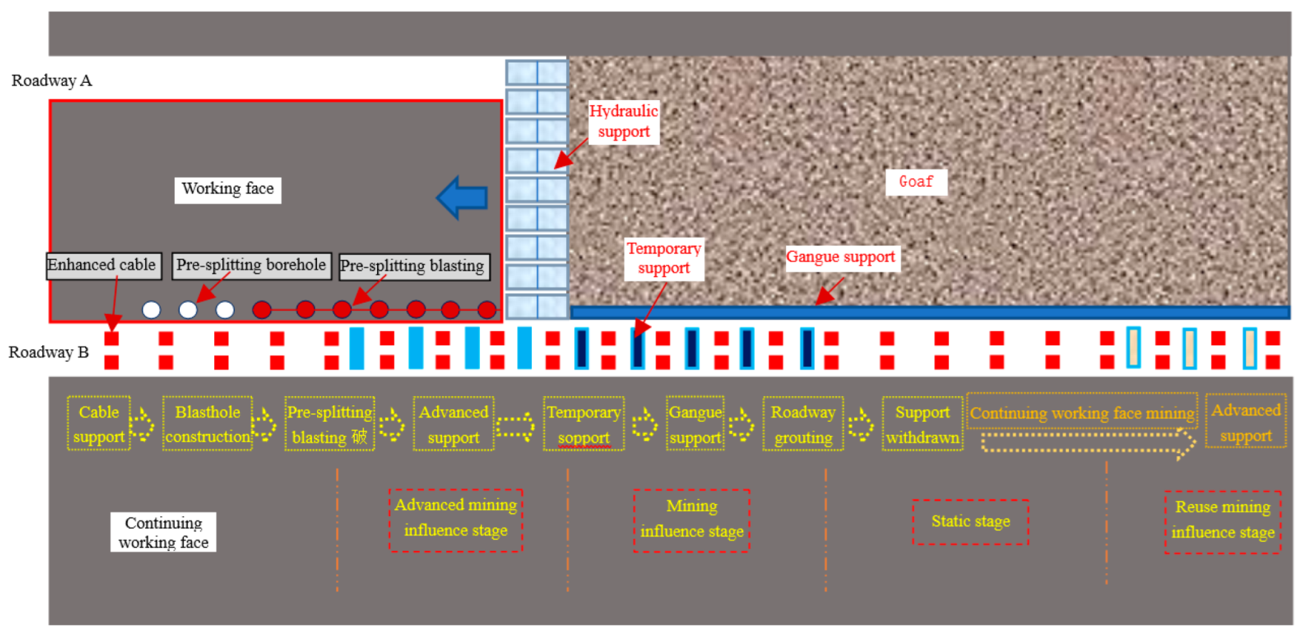
The process of GERRC and the surrounding rock control stage are shown in
Figure 1 [
20,
21,
22]. At present, the research on the movement characteristics and stability mechanism of the surrounding rocks of GERRC mainly focuses on the movement and stability control of the surrounding rocks in the mining influence stage. Combining the methods of model tests and numerical analysis, the deformation law of the surrounding rock and the characteristics of the overburden movement of GERRC was proposed by Suchowerska [
23] et al. The mechanism of CRLDAC and roof pre-splitting blasting for controlling the surrounding rock of GERRC was revealed by Karatela et al. [
24] through mechanical analysis and in-site monitoring, as well as the stability mechanism under the effect of roof cutting in thick coal seams [
25]. Through a three-dimensional physical model test, the caving characteristics and stress migration law of the overlying strata were summarized by Rezaei. [
26] along the roadway strike and dip directions, then the mechanical structure model of the key block of the retained roadway roof was installed, and the reasonable support resistance for the roadway roof was derived. A structural mechanics model of the short cantilever beam structure of GERRC was constructed by Coggan et al. [
27] in a thick coal seam. Based on the short cantilever beam structure of GERRC, roadway control countermeasures including roof cable, roadside bolt, and temporary support were proposed by Wilson [
28] et al. Summarizing the experience of field engineering practice of GERRC, the simplified mechanical model of roadway immediate roof was illustrated by Van [
29], likewise, the force changes law was obtained. According to the characteristics of roadway surrounding movement, the GERRC was divided into three sections: the section ahead of the working face, retained roadway influenced by dynamic pressure, and the stable section of the retained roadway by Gao et al. [
30,
31], based on this, mechanical analysis of the roof structure in the above three sections was conducted to study the stability control measures respectively. Joint support technology was proposed by Vennes et al. [
32] for the deeply buried roadway formed by roof cutting. After analyzing the field monitoring data, the effect of pre-splitting blasting on roof stability and roadway surrounding countermeasures was studied by Guo [
33] et al.
The above analysis mainly focused on the technical mechanism, surrounding rock structure, and supporting forms of GERRC. By analyzing lots of engineering application cases, the determination principles of support and pre-splitting blasting parameters are obtained. In the follow-up study, the relevant parameters can be determined with the help of the above principles. However, the main research object of the existing research is the rock stratum within a small range around the retained roadway, and there is a lack of relevant research on the stability of surrounding rock under the influence of static pressure after the withdrawal of temporary support. Therefore, it is very necessary to carry out the research on structural evolution and stability analysis of the retained roadway surrounding rock from the perspective of a large-scale and full cycle.
Although many achievements have been made by basic theoretical research and field application under all kinds of complex conditions of GERRC, there are still unsolved problems. For example, there are two significant problems, one of which is the lack of scientific theoretical calculation guidelines for whether the short-arm roof will break and thus cause roof collapse; the other is the lack of judgment basis for stability reliability of the surrounding rock after the withdrawal of temporary support. The above two problems make some application coal mines cannot withdraw the temporary support equipment in time, resulting in excessive equipment investment. The stability of the surrounding rock of retained roadway is a necessary condition to ensure the reusability of the roadway, to solve the above two problems, it’s necessary to carry out research on the structural movement characteristics and stability mechanism of GERRC. Therefore, the purpose of this study is to reveal the breaking criteria of the cantilever beam structure and the mechanism of stress transfer of roof cutting roadway, and, to achieve this it is necessary for us to analyze the evolution law of surrounding rock structure in different scales and choose to specify efficient support countermeasures accordingly.
2. Movement Process of Surrounding Rock of GERRC
The key points of GERRC lie in roof cutting and gangue bulking and filling. Roof cutting can achieve 3 favorable effects: (1) cut off the overall structural relationship between the roof of the roadway and the roof of the mining area, so that the roof of the mining area will not hang for a large span, and realize the effect of roof collapse with mining; (2) cut off the mechanical transfer path between the roof of the roadway and the roof of the mining area so that the disturbance from the roof collapse of the mining area is greatly reduced; (3) realize the bulking gangue filling, after the roof collapse of the mining area, due to the bulking characteristics of the rock, the collapsed immediate roof can effectively fill the mining space, reducing the movement space and intensity of the overlying rock strata.
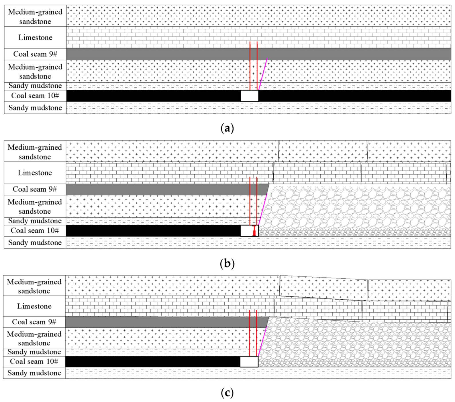
The process of roof cutting and gangue bulking would then be the process of the surrounding rock movement of GERRC, which mainly includes: (1) constant resistance and large deformation anchor cable support and pre-splitting blasting before mining, as shown in
Figure 2a; (2) immediate roof collapses and fills mining space insufficiently after mining, then the basic roof breaks and deforms, during which the roof movement is violent, it´s necessary to carry out temporary roof support, as shown in
Figure 2b; (3) With the settlement movement of the overlying rock strata, the gangue compaction can be achieved eventually, the roof movement maintains in a low level, and finally, the roadway reaches a stable state, as shown in
Figure 2c.
Before the mining of the working face, the process of reinforcement support and pre-splitting blasting are indispensable for the roadway roof. After supporting the roadway roof with CRLDAC, the higher preload can significantly improve the integrity and strength of the roadway roof strata in the early stage of support. At the same time, the mechanical characteristics of high constant resistance and large deformation of CRLDAC can ensure that the roadway roof remains stable under the influence of blasting load and mining pressure. Pre-splitting blasting can form a fracture plane along the roadway strike without affecting the roof strata in other directions. It can cut off the roadway roof and minimize the damage to the roof strata at the same time. After the mining of the working face, the roof of the goaf that has been cut off will collapse to the goaf in time. By reasonably designing the height of the cutting roof, the collapsed gangue will fill the goaf and limit the movement of the overlying strata. The retained roadway remains stable under the joint action of CRLDAC and temporary support in the roadway. After the gangue in the goaf is compacted densely and the basic roof forms a stable articulated rock beam structure, the surrounding rock of the roadway tends to be stable. In this way, the whole process of GERRC is completed.
3. Roof Breaking Guidelines of GERRC near Coal Pillar
Through previous research [
23], it is known that if the roof strata of GERRC rotates and deforms to break, the fracture is generally located above the solid coal seam. After roof cutting, the roadway roof is subjected to the comprehensive action of complex force systems such as the supporting body force, the temporary supporting force, the coal body support force, the support force of the lower rock strata, and the movement pressure of the upper rock strata, as well as its gravity. Therefore, the breaking of the roadway roof has an important significance to the analysis of the stability of the surrounding rock and its control countermeasures, and its breaking characteristics are not only related to the force, but also have an important relationship with the thickness and mechanical properties of the rock strata itself.
The roadway roof is simplified as a cantilever beam, the left side of the beam is the fixed end, and the right side of the beam is the free end. The upper and lower parts of the beam are in contact with the overlying strata and the immediate roof strata. The mechanical model of the cantilever roof structure is shown in
Figure 3.
The forces in the figure above are all forces per unit width along the strike direction, where: Fd is the force of the overlying rock stratum, Fu is the combined force that plays a supporting role on the rock stratum, mainly including the supporting body force, the temporary supporting force, the coal body support force, the support force of the lower rock stratum, Lc is the length of the cantilever beam, G is the gravity of the cantilever beam, Hc is the thickness of the cantilever beam.
The roof beam is cracked from the end
D, the mechanical condition is as follows:
σ is the actual tensile stress at cracking
D, the magnitude of which is the difference between the stresses acting on the structure of the simply supported beam, and can be described as follows:
where
σ1 is the tensile stress generated by the force system at point
D;
σ2 is the compressive stress generated by the force system at point
D.
Under the action of
σ1, the beam will bend and deform, so
where
MD is the moment of
Fd and
G at point
D of the rock strata,
WD is the flexural modulus of the cantilever beam, which can be expressed in the following form:
Substituting Equations (4) and (5) into Equation (3) yields:
Similarly,
σ2 can be obtained as follows:
Substituting Equations (5) and (8) into Equation (7) yields:
Therefore, the actual tensile stress at point
D is as follows:
From the analysis of Equation (10), it can be seen that the combination of force σ with the support role of the rock beam is obvious. The larger Fu and the smaller σ force, the less likely the rock beam is to break.
Fu mainly includes the support body force, temporary support force, coal body support force, the support force of the lower rock stratum, and Fd is the force from the overlying rock stratum, these forces are not easy to control, the calculation is more difficult, and is not conducive to fracture determination. However, the most intuitive result of the above forces in the field is the deformation of the surrounding rock, so we can transform the force relationship analysis into the deflection analysis of the beam, and then convert the formula.
The maximum deflection of the rock beam can be expressed as:
where
Ymax is the maximum deflection at the end of the rock beam,
E is the modulus of elasticity of the rock beam, and
I is the inertia moment of the beam section.
I can be calculated from the following relation:
Through the substitution of Equation (4), (8), and (12) into Equation (11), the maximum deflection at the end of the rock beam can be expressed as:
Equation (13) can be transformed to the following form:
Finally, if Equation (14) is substituted into Equation (10), the actual tensile stress at point
D is estimated as:
The greater the increase in the thickness of the cantilever beam, the smaller the tensile stress at point D, which means that the less likely the rock beam is to fracture. Conversely, the greater the increase of the maximum deflection at the end of the rock beam and Young’s modulus of the rock beam, the greater the tensile stress at point D, which indicates that the more likely the rock beam is to fracture.
The thickness and Young’s modulus of the rock beam are the properties of the rock beam itself, therefore, the only variable that can be controlled is Ymax. In the process of surrounding rock control, strengthening the temporary support strength of the roof, and then reducing Ymax, can prevent the roof rock beam from breaking.
Therefore, when
there is no breakage occurred in the roof rock beam and a single-peak stress field forms on the roadway roof, when
the roof strata breaks, and internal and external stress fields within the roof rock form. After the application of roof cutting technology, the roadway roof is artificially cut off, which makes the roof of the gob collapse sufficiently, and the gangue stacking height after crushing and swelling is large, so as to reduce the maximum deflection at the end of the rock beam above the roadway. Through the analysis of the above formula, it can be seen that the reduction of
Ymax will increase
LC, making the breaking position of the cantilever move to the deep part of the coal body. The consequence of the above series of changes is that the width of the internal stress field increases, and at the same time, the peak of the lateral abutment pressure also moves away from the roadway, which effectively improves the stress environment of the surrounding rock of reserved roadway.
4. Structural Model of Double-Arch Roadway Protection of GERRC
- (1)
The formation of the double balanced arch structure
In the process of immediate roof collapse, basic roof, and overlying rock beam movement, the roadway roof will be subject to dynamic load impact. That is, within 2 basic roof weighting steps lagging behind the working face is the stage of violent movement of the roadway roof, it is necessary to rely on active CRLDAC support and passive single shed or unit hydraulic support for the roadway stability control. When the goaf gangue is stabilized under the compression of the overlying rock stratum, the overlying rock movement tends to be stable, at this time, the double-arch structure of the overlying rock layer achieves structural and mechanical equilibrium, as shown in
Figure 4.
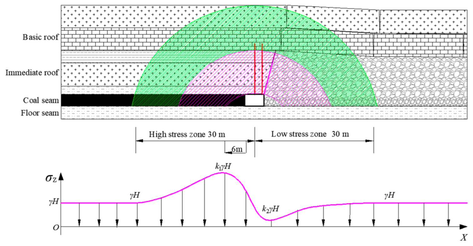
The first mechanical-structural equilibrium arch (areas marked in magenta in
Figure 4), referred to as the immediate balance arch, is formed under the joint action of roadside goaf gangue, roadway support, and short-arm rock beam. The immediate balance arch bears most of the load transferred from the overlying rock stratum to the roadway surrounding rock, and therefore plays a decisive role in the success of GERRC.
The other mechanical-structural equilibrium arch (areas marked in green in
Figure 4), referred to as the main balance arch, is formed under the joint action of the entire goaf gangue, solid coal seam, and the articulation of the basic roof and the overlying rock beam. The main balance arch bears most of the overlying load of the slope and therefore plays a critical role in the stability of the immediate balance arch.
Affected by the roof cutting, the concentrated stress of solid coal on the left side of the roadway is reduced as a whole and shifted to the deeper part. The influence range on the left side of the double-arch is about 30 m, which is the high-stress area, where the peak concentrated stress is about 6 m from the solid coal roadside; the influence range on the right side of the double-arch is about 30 m, which is the low-stress area. The retained roadway is exactly located in the stress reduction zone, which also strongly demonstrates the pressure relief effect after roof cutting.
Under the joint action of double balance arch consisting of immediate balance arch and main balance arch, the integrity of the roadway is protected, and the surrounding rock structure of the roadway is balanced, finally the safe and stay entry retaining is achieved.
- (2)
The force of falling gangue on the gangue-retaining structure and roadway roof
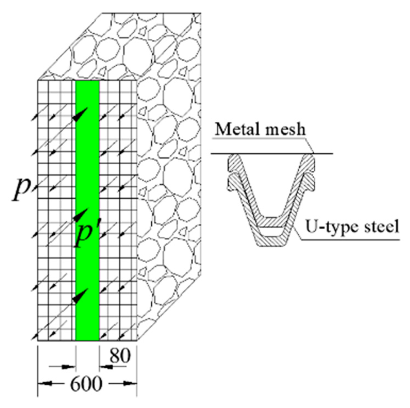
Taking Dianping mine which locates in Shanxi province as an example, the width of the U-type steel is 80 mm, and the spacing is 600 mm, the layout of the gangue-retaining U-type steel is illustrated in
Figure 5. The lateral pressure
p of gangue is 0.13 times the lateral pressure
p′ of the U-type steel, that is,
p = 0.13
p′.
The monitoring curve of the lateral compressive stress of the gangue in the process of entry retaining is shown in
Figure 6. As shown in
Figure 6a, when the distance behind the working face reaches 90 m, the lateral pressure value gradually tends to stabilize. The lateral stress
p′ applied to the U-type steel is stabilized at about 1.8 MPa, and the lateral pressure
p of roadside gangue is 0.24 MPa according to the relationship mentioned above. As shown in
Figure 6b, when the distance behind the working face reaches 100 m, the lateral pressure value gradually tends to stabilize, and the lateral stress
p′ and
p remain unchanged. The monitoring data of the two monitoring points show that after 90–100 m behind the working face, the compression deformation of the gangue in the goaf gradually tends to be stable, and the final lateral pressure
p and
p′ are maintained at about 0.24 MPa and 1.8 MPa, respectively.
The structural and mechanical model of the stabilized roadway surrounding rock is shown in
Figure 7.
The vertical support force of gangue to the roadway roof on the unit strike length is
Substituting p = 0.24 MPa, Hf = 9 m, θ = 15° into the above formula, the ultimate vertical support force comes out to 559 kN. Due to the formation of a cantilevered roadway roof at the gob-side end after roof cutting, the support force of gangue on the roadway roof will play an important role in maintaining the stability of the roadway.
5. Numerical Analysis of the Structure and Movement of GERRC
Taking the 10–100 working faces of the Dianping coal mine in Shanxi province as the engineering prototype, the two-dimensional UDEC model was constructed. The numerical model with a roof cutting angle of 15° and a roof cutting borehole depth of 9 m is shown in
Figure 8. According to the coal seam burial depth and ground stress, a vertical load of 6 MPa is applied to the top of the model. A load with a lateral pressure coefficient of 0.5 is applied around the model for horizontal restraint, and a displacement boundary is applied to the bottom of the model. By simulating the mining processes of roadway excavation, working face recovery, immediate roof collapse, and basic roof breaking, the overlying stratum movement and structural characteristics of GERRC are analyzed, as well as the deformation development of roadway surrounding rock and stress redistribution law.
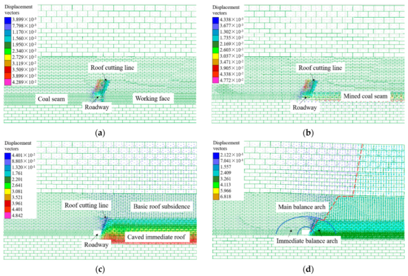
Through the roadway and working face excavation, the evolution of the displacement field of the surrounding rock of GERRC is shown in the following
Figure 9.
It is inferred from
Figure 9a that the surrounding rock of GERRC remains stable after roof cutting, and the maximum sinkage of the roadway roof is 15 mm, which also proved that pre-splitting blasting of the roadway roof basically has no effect on the overall stability of the roadway before working face mining. As shown in
Figure 9b, after the recovery of the working face, the immediate roof begins to collapse, the collapsed gangue is in the state of loose accumulation, and the volume increases thus filling the goaf area. As shown in
Figure 9c, with the further subsidence of the overlying strata, the basic roof and the overlying strata have discontinuous subsidence due to distinct mechanical properties, resulting in layer separation. Finally, the gangue in the goaf is compressed to a stable state, and the movement of the roadway roof, the basic roof of the working face, and the overlying strata tends to cease. At this time, the gangue in the goaf and the short arm beam structure of the roadway form an immediate roof balance arch, and the hinged basic roof forms a basic roof balance arch after the roof is broken, as shown in
Figure 9d.
Figure 10 shows the evolution process of the displacement vector field of the surrounding rock of GERRC. As
Figure 10a shows, after roadway excavation and roof cutting, the overlying strata form a bidirectional displacement field bounded by the slit surface, indicating that the roof cutting was able to cut off the displacement field within the immediate roof.
Figure 10b shows that after the excavation of the working face, the vertical displacement field of the immediate roof begins to appear, indicating that roof cutting can promote the collapse of the immediate roof in time.
Figure 10c shows the vertical displacement field of the basic roof and the overlying strata after the immediate roof crushing and swelling filling the mining space, indicating that the overlying strata began to sink. When the movement of the basic roof and the overlying strata tends to be stable, and the caving gangue is compressed and compacted, connect the points with the same displacement to form the red line shown in
Figure 10d, which is called the boundary line of roof sinking. The maximum subsidence of the roof on the left side of the boundary line is 212 mm, indicating that the rock stratum is stable, and the subsidence is small under the protection of the double arch structure. The angle of the sinking boundary of each rock stratum is the same as that of the pre-splitting slit drilling, indicating that after the roof cutting, the breaking of the overlying rock stratum basically develops upward according to the roof cutting angle, that is, the roof cutting plays a role in guiding the orientation of the roof fracture.
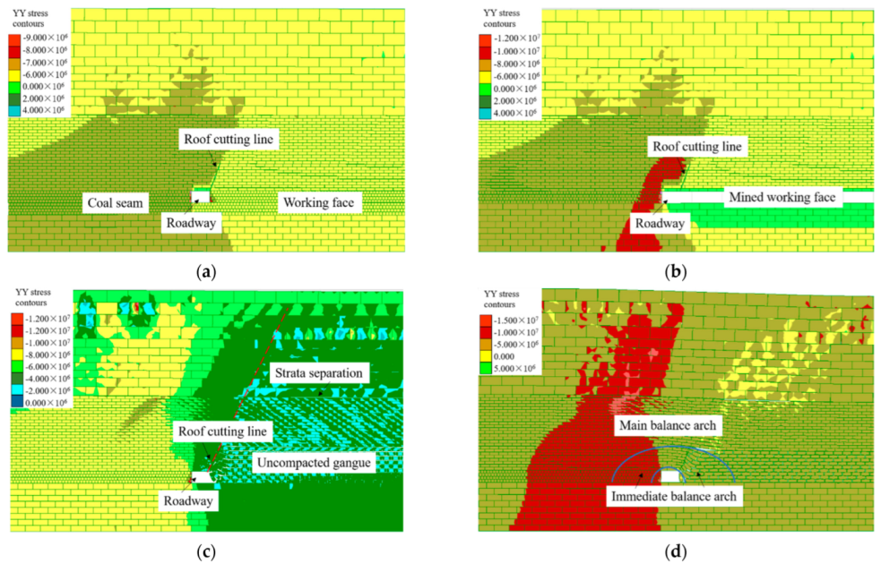
Figure 10 shows the evolution process of the stress field of the surrounding rock of GERRC. As shown in
Figure 11a, after roadway excavation and roof cutting, the stress field within the immediate roof range is obviously divided into two areas, indicating that roof cutting can cut off the stress transmission path of roof rock. As shown in
Figure 11b, after the excavation of the working face, the immediate roof collapses along the roof cutting line, and concentrated stress appears on the solid coal side. With the compression of the gangue in the goaf, the basic roof also begins to sink, so that the roof stratum above the goaf and roadway is located in the low-stress area, as shown in
Figure 11c. This shows that after the roof is cut, the pressure relief effect is realized by controlling the roof collapse of the working face and avoiding the transmission of stress to the immediate roof of the roadway. As shown in
Figure 10d, When the basic roof and the overlying rock layer are stabilized, the immediate roof balance arch and the basic roof balance arch are formed. At this time, the roadway roof, the gangue in the goaf, and the fractured basic roof are basically in the same stress field, while the stress concentration is formed on the solid coal side of the roadway under the cantilever action of the overlying strata. The left edge of the concentrated stress field presents obvious arc distribution characteristics, which is perfectly consistent with the depicted double arch structure, and also proves the accuracy and rationality of the double arch theory.


 ,
, 


