Article

Prediction of the Adaptability of Using Continuous Extraction and Continuous Backfill Mining Method to Sequestrate CO2-A Case Study

1
Key Laboratory of Deep Coal Resources Mining, China University of Mining and Technology, Ministry of Education, Xuzhou 221116, China
2
School of Energy, Xi’an University of Science and Technology, Xi’an 710054, China
*
Author to whom correspondence should be addressed.
Minerals 2022, 12(8), 936; https://doi.org/10.3390/min12080936
Submission received: 17 June 2022 / Revised: 20 July 2022 / Accepted: 22 July 2022 / Published: 25 July 2022
(This article belongs to the Special Issue Solid-Filling Technology in Coal Mining)

Abstract

:
The consumption of coal resources has caused an increase in CO2 emissions. A scientific concept that can realize CO2 sequestration, the harmless treatment of solid wastes, and coal extraction under buildings, railways, and water bodies (BRW) is proposed. First, a novel CO2 mineralized filling body (CMFB) is developed by employing CO2 gas, fly ash, silicate additives, and cement. It is then injected into the mined-out mining roadways (MRs) of the continuous extracting and continuous backfill (CECB) mining method to ameliorate the overburden migration and thus extract the coal body under the BRW. The AHP-fuzzy comprehensive evaluation method was employed to construct a prediction model for the suitability of this concept. Subsequently, the evaluation model is generalized and applied to the Yu-Shen mining area. Each indicator affecting adaptability is plotted on a thematic map, and the corresponding membership degree is determined. The aptness for 400 boreholes distributed in the entire area was determined and a zoning map which divides the whole area into good, moderate, slightly poor, and extremely poor suitability was drawn. This paper puts forward a mathematical model for predicting the suitability of using CECB and CMFB to sequestrate CO2. Research results can provide references for determining the site of CO2 sequestration under the premise of maximizing the economic and ecological benefits, which is conducive to constructing ecological, green, and sustainable coal mines.

1. Introduction

Coal consumption accounts for 70% of primary energy consumption, making significant contributions to China’s economic development [1,2,3]. However, large-scale and high-intensity coal extraction has resulted in overburden breakage, water-conducting fracture development, and surface subsidence. If water diversion channels between the underground aquifer and the mined-out area occur, large amounts of water will flow into the gob, leading to the water inrush or even the sand inrush [4,5,6,7,8]. In addition, the original balance state of recharge, runoff, and discharge of the aquifer will be broken, and a drastic decline in water level and a large range of water resource loss will be inevitable [9,10]. Furthermore, severe mining disturbance causes ground subsidence, contributing to the damage of the surface buildings and structures. The relocation of villages is therefore unavoidable [11,12,13,14].
On the other hand, the utilization of coal resources has produced large amounts of CO2 gas [15,16], indicating the importance of CO2 sequestration. In-depth research on predicting the adaptability of CO2 sequestration has been carried out at home and abroad. Thanh and Kim used knowledge-based machine learning techniques to predict CO2 sequestration performance and its storage efficiency in underground saline aquifers [17,18]. Ahmadi accurately forecasted the properties of carbon dioxide for carbon capture and sequestration operations using an artificial neural network and the least squares support vector machine [19]. Furthermore, Thanh also constructed a geological model to precisely predict CO2 storage capacity in a fractured basement reservoir in Vietnam using numerical simulation [20]. He Liping investigated the potential for geological sequestration of CO2 from the oil field in the vicinity of Yulin City [21]. In addition, Edo identified the appropriateness of the coal seams for CO2 sequestration with enhanced coalbed methane recovery in the South Sumatera Basin, Indonesia [22]. Hung applied the artificial neural network to predict the performance of CO2-enhanced oil recovery and storage in residual oil zones [23]. Furthermore, Muhammet compared the performance of three fuzzy-based multi-criteria decision-making methods to determine the geological storage site of CO2 in Turkey [24]. Conventionally, CO2 gas adhering to coal-based solid waste such as fly ash is a decent choice to deal with the increasing CO2 gas. Inspired by this assumption, a novel scientific concept is proposed, sequestrating CO2 gas to fly ash to develop the CMFB at ambient temperature and pressure, and then injecting the CMFB into the mined-out area in underground coal mines under BRW. The concept is “Trinity” for green mining since it not only copes with the excessive CO2 gas but also realizes the harmless treatment of coal-based solid waste as well as protects the overlying water bodies and surface buildings. Moreover, to maximize benefits and reduce costs, the concept is especially appropriate for coal extraction under BRW.
This prospective investigation is of great significance for green mining and the sustainable development of coal mines. First, coal-based solid wastes, such as fly ash and gangue, accumulate on the ground, and the soil and shallow water are prone to be polluted by the leaching process. These solid wastes will be employed to develop CMFB in the future, which is conducive to the harmless treatment of solid wastes. Furthermore, excessive CO2 emissions have caused a series of environmental problems, such as the greenhouse effect. The concept of adhering CO2 to fly ash or other solid wastes at normal pressure and temperature is advantageous for large-scale and excessive industrialized CO2 gas sequestration. This is essentially different from the traditional CO2 mineralized coal-based solid waste technology, which needs catalytic nucleation at high temperature and pressure to improve the reaction rate of CO2 and mineralized nodule rate. Exploration and development of CMFB at ambient temperature and pressure is thus of great engineering and ecological significance. Third, high-intensity coal extraction has caused drastic overburden migration, water table lowering, and surface subsidence. The CECB mining method is generally employed to ameliorate or deal with these problems by extracting the coal resources trapped under BRW.
In addition, it is necessary for the CO2 mineralization process to be implemented in a confined space, and the dimension of the closed space should be adjustable and flexible [25]. Meanwhile, the MR of CECB mining is characterized by a modifiable size and good leak resistance. Moreover, the limited roof exposure of CECB mining makes it feasible for the CMFB to reach the design strength before roof subsidence, which is conducive to the stability of the filling body [26]. Therefore, all these requirements for permanent CO2 sequestration are consistent with the characteristics of CECB mining [27]. In this regard, it seems that using CECB to sequestrate CO2 is currently the most reasonable and scientific method to deal with the above-mentioned problems.
However, the complex engineering and hydrogeological conditions of the coal mines and the characteristics of CMFB and CECB mining have influenced the suitability of this concept [28,29,30]. CO2 sequestration using CECB is restricted by many factors, i.e., the roof and floor conditions, the BRW conditions, geological structures, mining block conditions, coal seam conditions, and the CMFB system [31,32,33,34,35]. Therefore, it is necessary to systematically consider these influencing factors and use a comprehensive evaluation method to predict its feasibility in different collieries [36]. The commonly employed comprehensive evaluation methods include AHP, the Delphi method, weighted mean method, fuzzy comprehensive evaluation, principal component analysis, BP neural network method, etc. [37]. AHP, proposed by Professor Saaty, is a practical method for multiple schemes or multiple objectives. It is a decision-making analysis method that combines qualitative and quantitative analysis, and it is widely employed in many sectors of society [38,39]. For instance, it is widely used for conducting investigations and assessments of the water quality and hydrochemical features of groundwater [40]. In addition, the method can be employed to predict the development of macro- and micro-cracks in diverse conditions by combining it with other methods [41]. It can also be employed to predict the ground fracturing and crack propagation laws under the conditions of dynamic loading [42,43,44]. Furthermore, AHP can also be utilized to assess the mining-induced stress field and the movement of overburden, to better analyze the mining disturbance and the appropriateness of using the CECB method and CMFB to sequestrate CO2 [45,46,47,48].
In view of the aforementioned problems, we intend to conduct a prospective investigation into the development and application of CMFB at normal temperature and pressure, as well as the UCS test of the CMFB with various material ratios and setting times [49,50,51]. On this basis, the AHP-fuzzy comprehensive evaluation method will be employed to construct a mathematical model to predict the adaptability of this concept. The model will be generalized and applied in the Yu-Shen mining area. The thematic map of each indicator affecting the applicability in the entire coal area will be plotted to determine the membership degrees [52,53,54]. Subsequently, the comprehensive evaluation value Φ reflecting the grade of adaptability for 400 boreholes in the Yu-Shen coal area is determined by combining the weight distribution and membership degree. The entire coal area is classified into four categories, i.e., good, moderate, slightly poor, and poor suitability.
This paper proposed a concept that involves developing CMFB and injecting it into mined-out areas to support the roof, contributing not only to the harmless treatment of solid wastes and CO2 gas but also making significant contributions to coal extraction under BRW. The research results of the prediction model can provide a theoretical reference for the realization of CO2 mineralized filling in collieries in the future, which is conducive to green and sustainable mining.

2. CO2 Sequestration Using CECB Mining Method

Prior to CECB mining, the mining panel is divided into many MRs, and then the MRs are allocated into different mining phases (generally 3–5). The three-dimensional sketch map of the MRs arrangement of the CECB method is shown in Figure 1. The schematic map of the processes of this method is shown in Figure 2. With due consideration of the ventilation and excavation as well as the roof subsidence caused by CECB mining, the length of MR is generally less than 150 m and its width usually ranges from 4.0 to 7.0 m. To facilitate the turning of the continuous shearer and the hydraulic drilling rig, the angle α between the MR and the headgate ranges from 40 to 60°. Due to the restriction on the height of the mining equipment, such as continuous shearers, etc., the height of MR is generally lower than 5.5 m. This method avoids the problem of uncoordinated operations between mining and filling during the longwall filling mining method, which is not conducive to conducting the filling process of CMFB. To effectively control the movement of the overlying strata and avoid surface subsidence, each MR is sealed and backfilled with CMFB immediately after the coal body is extracted. The MRs in the second phase will be extracted and backfilled after all the MRs in the first phase are mined and backfilled. Finally, the coal body in the entire mining panel is completely substituted with the CMFB, and the CO2 gas can be sequestered in the form of solid CMFB. The replacement of carbon and coal can be realized by using the CECB mining method and CMFB.

3. Development and Mechanical Test of CMFB

3.1. Preparation of CMFB Specimens

In this paper, the proportions of low-calcium fly ash and the curing time are selected as the variables while the silicate additives, as well as the flow rate and concentration of CO2, gas are invariant. In this context, the control variable method is employed to design the testing schemes. The strength characteristics of CMFB samples are subject to the water-solid ratio. The ratio of the water weight to the total CMFB of 30% is invariable. In other words, the water-solid ratio is set to a constant of 3:7. The schemes consist of four groups, i.e., FA 55, FA 65, FA 75, and FA 85. The symbols FA 55, FA 65, FA 75, and FA 85 refer to the ratio of fly ash to the total amount of fly ash and cement is 55%, 65%, 75%, and 85%, respectively. For mechanic testing of UCS, the setting times are set to 3 d, 7 d, 14 d, 28 d, and 56 d, respectively. Three specimens are prepared for each curing time and each fly ash content. The number of the specimens for compressive testing is therefore at least 4 × 5 × 3 = 60. The testing scheme is designed and listed in Table 1.
Both the development of CMFB specimens and the mechanical test are carried out under the regulation of the national standard (GBT17671-1999). The detailed process of CMFB sample preparation and mechanical experiment is shown in Figure 3.
First, weigh the fly ash and cement and mix them evenly. Meanwhile, weigh and put the silicate additive into a container and keep stirring until all the particles are dissolved. The silicate additive was dissolved in tap water by stirring at 600 rpm for 15 min at room temperature, as shown in Figure 3a–c. Subsequently, the dissolved solution is immediately poured into the homogeneous mixture of fly ash and cement, and continued stirring until a uniform paste is obtained. The paste was then poured into the reactor, and the motor started and stirred at 500 rpm while CO2 gas was introduced at a constant rate of 1 L/min under atmospheric conditions. The entire stirring time lasted 20 min, and then the fresh slurry of CMFB is achieved, as shown in Figure 3d–f. Then, the filling slurry was decanted into standard moulds with a size of φ×h of 50 mm × 100 mm for UCS experiments. Twelve to fifteen hours later, the samples are taken out and put into the standard curing box. Its humidity is adjusted to approximately 98% and the temperature remains at 20 °C. Samples of CMFB are cured for 3, 7, 14, 28, and 56 days, respectively. Afterwards, the specimens are taken out of the curing box in batches. The dimensions are calibrated to make the specimens standard ones for the UCS test. After that, the UCS experiments were implemented, as shown in Figure 3g–o.
The diagrammatic drawing of the chemical reaction of CO2 gas and fresh slurry is shown in Figure 4.

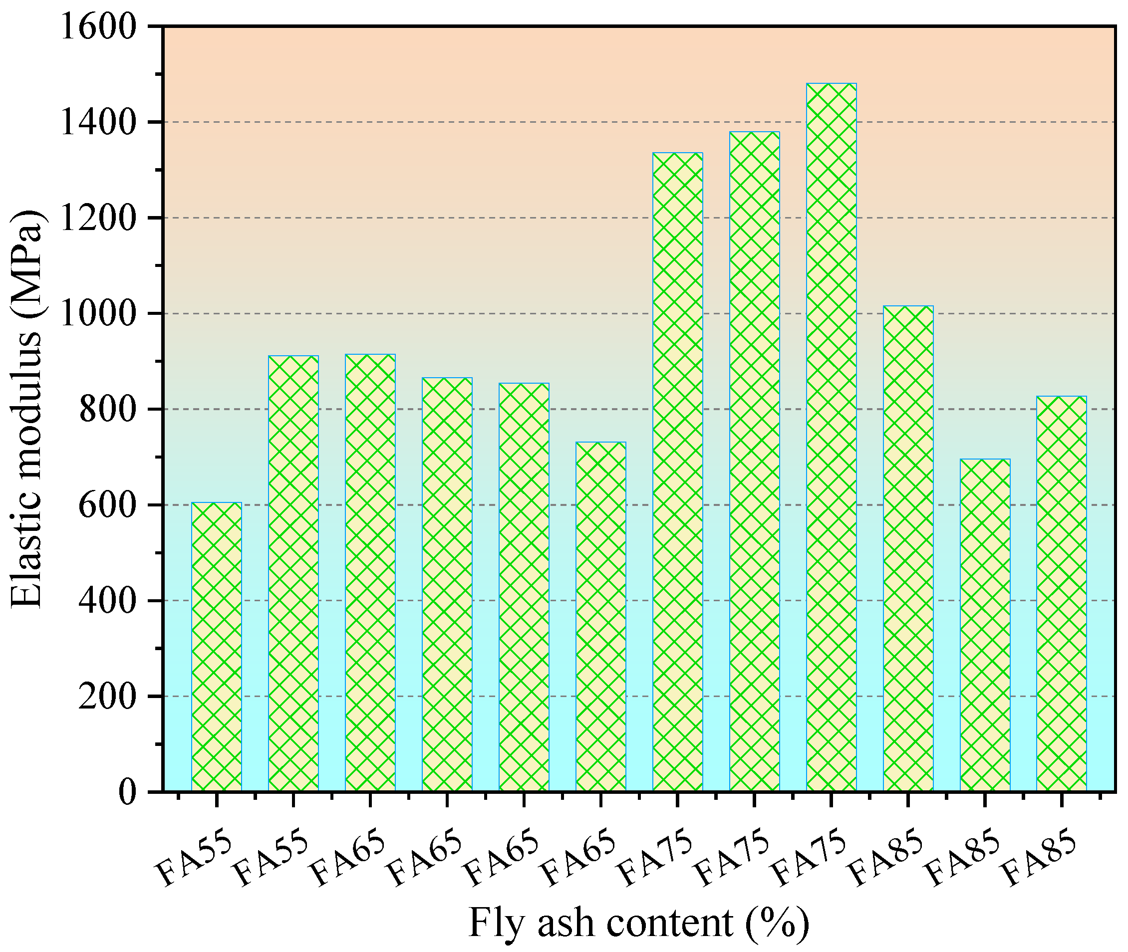
3.2. Testing Results of UCS and Elastic Modulus of CMFB

The changing law of UCS of CMFB corresponding to various proportions of fly ash and curing times are shown in Figure 5a,b, respectively.
Scholars working on the development of paste filling bodies generally believe that increasing the proportion of fly ash will result in low backfill strength. The low hydration reaction and the fewer hydration products caused by the low fly ash content may account for this phenomenon [27]. In this paper, it is interesting that the UCS rises first and then drops with the increasing fly ash content, reaching the peak at 75% fly ash content. This trend is almost the opposite to that of cemented backfill without CO2. Note that, in the early stage of the test, we have developed a sample of CMFB with 95% fly ash. However, the UCS of 95% CMFB is too small to bear the preloading, and the creep phenomenon occurs during the UCS test.
The UCS of CMFB with 75% fly ash is 1.982, 2.356, 3.832, 4.162, and 7.499 MPa, respectively, when the curing time is 3, 7, 14, 28, and 56 d, respectively. The UCS of CMFB with 85% fly ash content is lower than that of CMFB whose fly ash content is 75% and 65% when the setting time is invariable. Therefore, the influence of the addition of CO2 gas and silicate additives on the strength of the CMFB is significant.
According to the results for UCS of CMFB from the laboratory, the elastic modulus is determined by calculating the slope of the linear elastic stage of the stress-strain curve:
E f = σ b σ a ε b ε a ,
where Ef is the elastic modulus of CMFB; σ a and σ b refers to the stress of the starting and ending point of the linear elastic stage, respectively; ε a and ε b represent the strain of the origin and the end of the linear elastic stage, respectively.
The results of the Young’s modulus calculation of CMFB with a curing time of 56 d are shown in Figure 6.

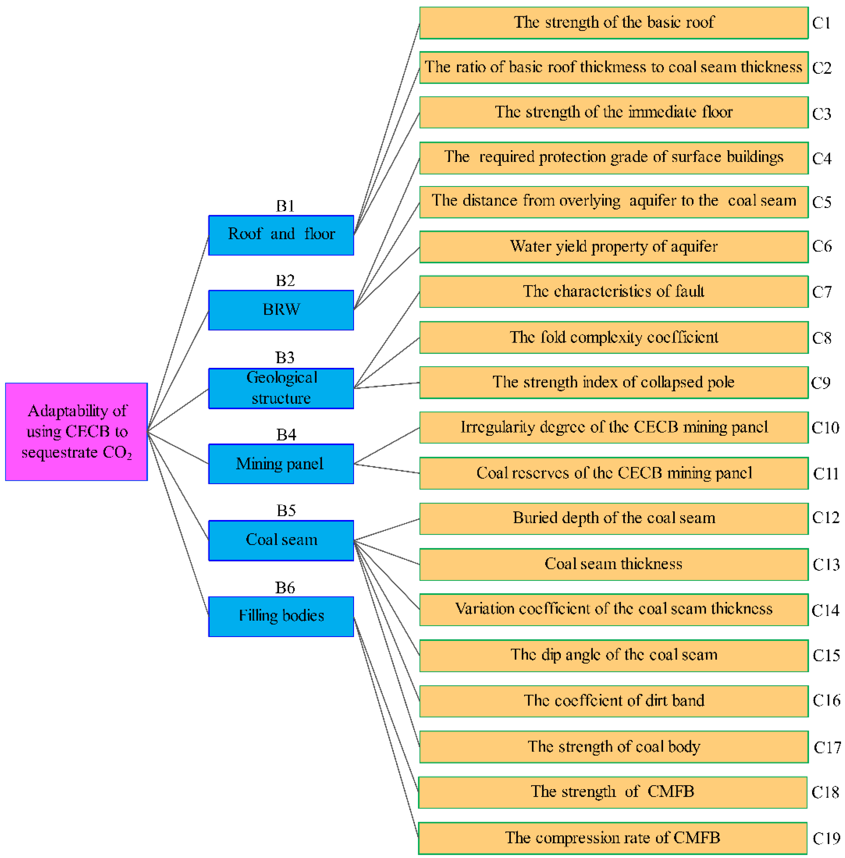
4. Determination of Indicators and Membership Functions

The indicators affecting the suitability of using CECB to sequestrate CO2 are complex and fuzzy, reaching good agreement with the characteristics and connotations of fuzzy mathematics. The combination of AHP with the fuzzy comprehensive evaluation method is capable of quantifying the factors and making them more concrete and accurate.
The AHP-fuzzy comprehensive evaluation method was employed to construct a triple-leveled structural model and obtain the distribution of the weights. The mathematical model includes six factors as secondary indicators, i.e., roof and floor system, BRW system, geological structures system, mining block system, coal seam system, and filling body system. Moreover, nineteen influencing factors, including the strength of the immediate roof, the distance from the overlying aquifer to the coal seam, the fold complexity coefficient, the coal reserves of the mining panel, the seam thickness, and the filling body strength, etc., were selected as tertiary indicators, as shown in Figure 7. Furthermore, the membership function of each indicator was analyzed and obtained based on the field practice of the CECB mining method, the UCS test of CMFB, and the summary of the current literature.

4.1. Roof and Floor System

4.1.1. The Strength of the Basic Roof

During the process of using CECB to sequestrate CO2, the strength of the basic roof should be considered since the soft roof may cause large amounts of roof subsidence despite the temporary support of the MR roof being adopted. Meanwhile, each mining equipment has a requirement for the height of MR. Therefore, the height of MR may be lower than that of the continuous miner and make it difficult to pass through, which will lower the adaptability of the concept. Therefore, the method of CO2 sequestration employing CECB can be carried out better in the coal mines with a hard roof. The firmness coefficient of the basic roof was selected as the evaluation standard.
The membership function of the firmness coefficient of the basic roof is as follows:
μ 1 a ( f r ) = { 0 ,             f r < 2 0.2 f r 0.4 ,     2 f r 4 0.1 f r ,             4 f r 6 0.2 f r 0.6 ,     6   f r 8 1 ,             f r > 8 ,

4.1.2. The Thickness of the Basic Roof

The basic roof controls the overburden migration and has an indispensable influence on the realization of using CECB to sequestrate CO2. The ratio of the thickness of the basic roof to that of the coal seam was selected as the evaluation standard.
k r c = 1 n i = 1 n H r i H c i ,
where n is the number of boreholes in the mining block; Hri is the thickness of the basic roof of the i-th borehole, m; Hci is the thickness of the coal seam of the i-th borehole, m.
μ 1 b ( k r c ) = { 0.2 , k r c < 2 0.6 , 2 k r c 4 0.8 , 4 k r c 6 1.0 , k r c > 8 ,

4.1.3. The Strength of the Immediate Floor

The strength of the immediate floor has a great influence on equipment transportation and worker passage. The argillaceous soft floor suffers from argillization, disintegration, expansion, and fragmentation soaked by water. The CMFB may mix with the disintegrated floor, contributing to a decline in strength. The transportation of mining equipment may be seriously affected, and the production efficiency will be reduced. Consequently, countermeasures such as immediate floor grouting reinforcement should be taken to make it feasible for CO2 sequestration in the CECB mining face. The firmness coefficient of the immediate floor was selected as the index.
μ 1 c ( f f ) = { 0 , f f < 1 ( f f 1 ) / 3 , 1 f f 4 1 , f f > 4 ,

4.2. BRW System

4.2.1. The Required Protection Grade of Surface Buildings

Mining-caused surface subsidence usually exerts a significant influence on BRW. There are five surface deformation indexes, i.e., vertical and horizontal displacement, inclination, curvature, and horizontal deformation. Different types of buildings have various abilities to anti-surface deformation, and when it exceeds the critical value, the buildings will be damaged. The corresponding damage levels and standards of the buildings regulated by state are listed in Table 2.
With due consideration of the economic and ecological benefits, the CO2 sequestration utilizing the CECB method is more suitable for extracting coal resources under buildings whose protection class is higher than grade II. For the coal seams trapped under the buildings, which need grade III protection class, partial mining, i.e., strip mining, room and pillar mining, and partial backfill mining methods, are the most suitable ones that can be employed to extract coal resources under BRW due to their low production cost. Additionally, for buildings that need a grade IV protection class, the coordinated mining and slice mining methods can meet the requirements. The CO2 sequestration using CECB can also be realized when the protective grade is III or IV, while the costs may be higher.
μ 2 a ( G ) = { 1.0 , G =   o r   G = 0.8 , G = 0.6 , G = ,

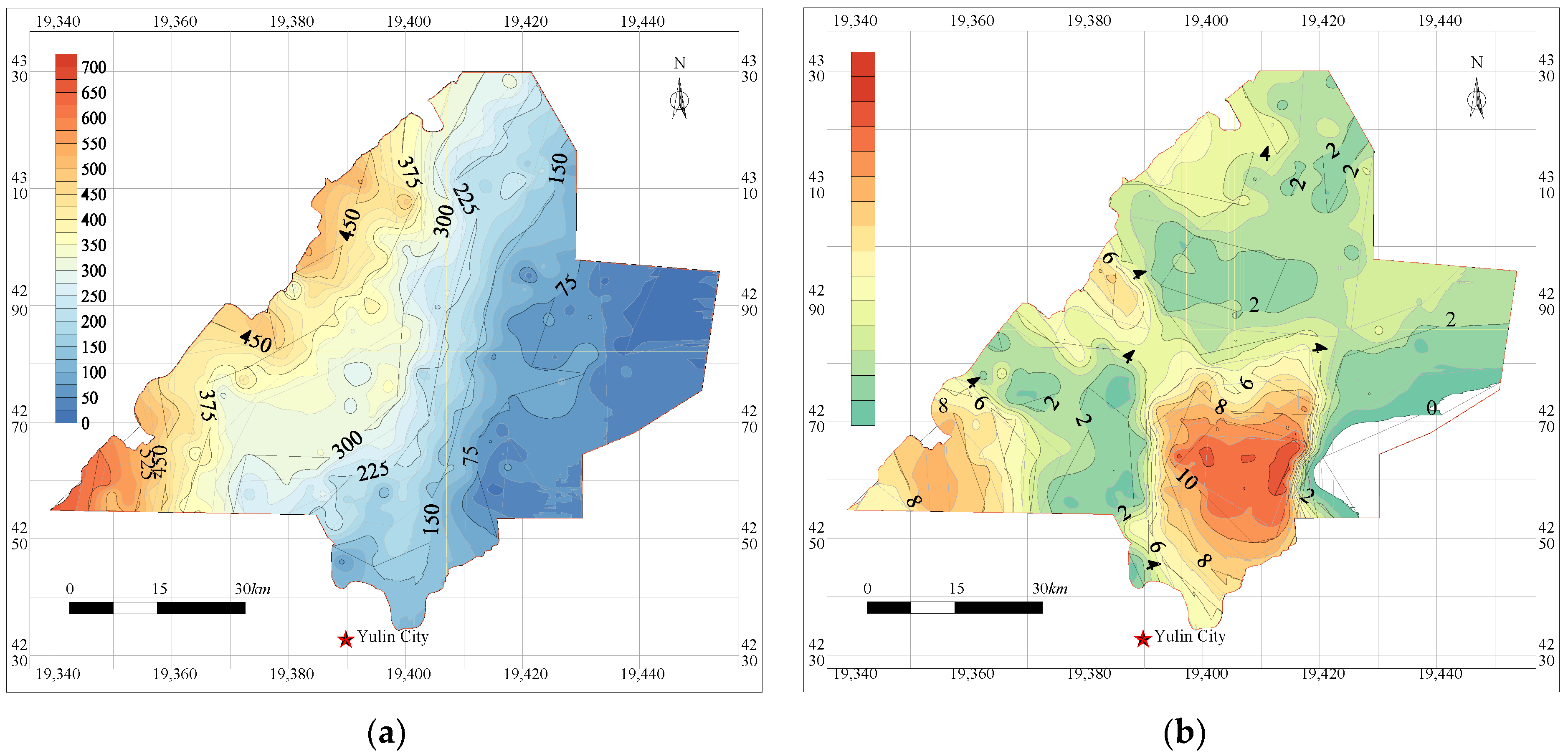
4.2.2. The Distance from Overlying Aquifer to Coal Seam

The height of the water-conducting fractured zone of the CECB method depends on the mining height, the CMFB strength, the overlying strata lithology, etc. During the process of generalizing and applying the CECB, it was found that after all MRs were extracted and backfilled, the height of the water-flowing fractured zone is approximately 5 times the mining height. Moreover, to prevent the overlying water bodies from penetrating into the mined-out area and thus resulting in a water inrush, the thickness of the protective zone between the top boundary of the fractured zone and the overlying aquifer was analyzed. The strength of various types of rock was employed to quantize the water-resisting indicator of the protection zone. The impermeability decreases with the increasing rock strength of the protection zone. Generally, a clay stratum with a thickness of more than 12 m can effectively preserve the water of the overburdened aquifer from percolating into the goaf [12]. Hence, if the water-resistant indicator of clay is set to 1, the values of the water-resisting index of other strata with various lithologies range from 0 to 1. Then the formula for the protective zone thickness can be expressed as follows:
H p = { 12 , H c 12 [ 12 + ( k 1 ) H c ] / k ,   0 H c < 12 ,
where Hp is the thickness of the protective zone (m); Hc is the thickness of the clay stratum (m); k is the water-resistant indicator of the protective zone.
If the distance is greater than the sum of the height of the water-flowing fractured zone and the thickness of the protective zone, the water-resisting layers can totally block the hydraulic interaction between the aquifer and the mined-out area. If the distance is only greater than the height of the water-conducting fracture zone, then the groundwater only permeates slowly in the overlying layers between the aquifer and the mined-out areas, and no water inrush accident will occur. However, when it is less than the height of the water-conducting fracture zone, the water-flowing fractures will reach the aquifer, contributing to a large-scale loss in groundwater resources and a decline in the water table. In this context, the concept is totally incapable of achieving its purpose of CO2 sequestration and water preservation under BRW.
μ 2 b ( d ) = { 0 , d H f 0.6 , H f < d H f + H p 1 ,   d > H f + H p ,
where d denotes the distance between the overlying aquifer and the coal seam, m; Hf denotes the height of the water conductive fractured zone, m; Hp denotes the thickness of the protective zone.

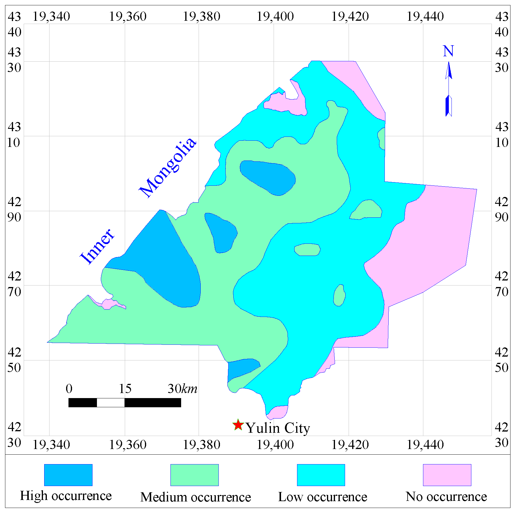
4.2.3. Water Yield Property of the Overlying Aquifer

The water yield of the aquifer is closely related to the thickness and the permeability coefficient of the aquifer. The larger the thickness and permeability, the higher its water storage and recharge capacity, and thus the higher the water-richness. With due consideration of the mining costs, the high water-richness means the high adaptability of CO2 sequestration using the CECB method since it is capable of controlling overburden migration and maintaining the stability and integrity of the aquifuge beneath the aquifer using the developed CMFB. According to the classification standard of aquifer water yield, the water abundance can be divided into three levels according to the unit water inflow of the borehole, as shown in Table 3.
μ 2 c ( w y ) = { 1 ,   w y = H i g h   o c c u r r e n c e 0.8 ,   w y = M e d i u m   occurrence 0.2 ,   w y = L o w   occurrence ,

4.3. Geological Structures System

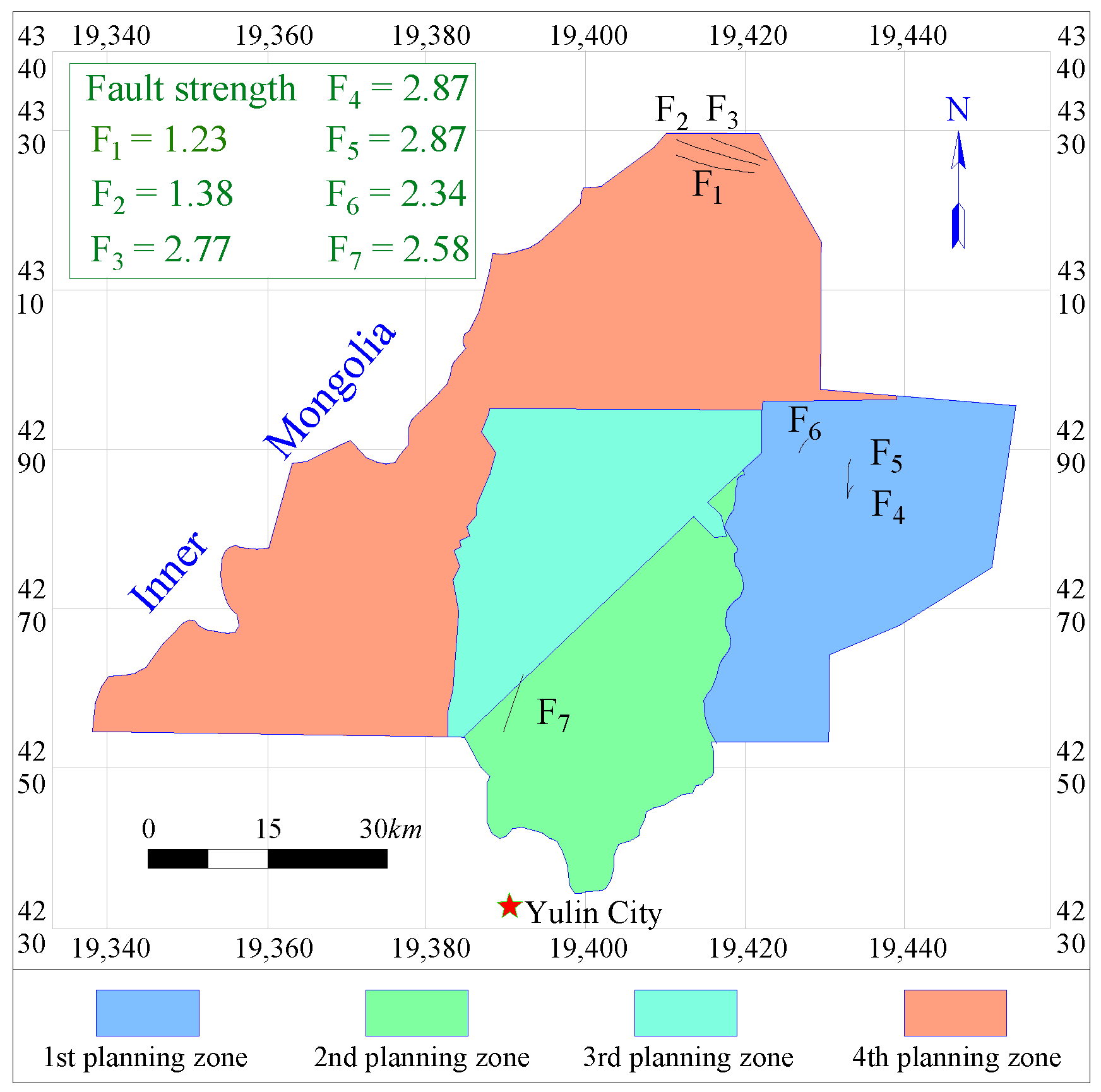
4.3.1. The Characteristic of Fault

The faults destroy the continuity and integrity of the overburden. The overlying strata near the medium and small faults are generally broken, which is prone to causing support break-off during the process of CO2 sequestration by the CECB. The large faults will disturb the original mining arrangement of MRs and thus lower the mining efficiency. The coal seam in the vicinity of the large faults is usually left unmined as the permanent protective coal pillar, leading to a low recovery rate of coal resources and a low storage rate of CO2.
The fault strength was selected as the evaluation indicator affecting the appropriateness of the concept. The formula of fault strength is as follows:
S = i = 1 k l i h i / A ,
where li refers to the length of the i-th fault (m); hi refers to the fault throw of the i-th fault (m); A refers to the area of the block (m2); k refers to the number of faults in the block.
The membership function of fault strength is:
μ 2 a ( S ) = { 1 , S 0.3 ( 25 50 S ) / 10 , 0.3 S 0.5 0 ,   S 0.5 ,

4.3.2. The Characteristic of Fold

There is high residual stress and elastic energy in the folded rock mass. When sequestrating CO2 in the MRs of the CECB, the elastic energy accumulated in the coal and rock mass is further released, which may lead to serious deformation of the MRs and even destructive rock burst of the surrounding rock. The development and complexity of the fold have an influence on the mining layout and mining sequence of the method. The fold complexity coefficient P was selected as the indicator.
P = Δ h w l s ,
where Δ h is the contour height difference between the lowest and highest coal seam in the CECB mining panel, m; w is the change value of the trend of the contour line expressed by radian, rad; l is the horizontal contour distance between the lowest and highest coal seam in the CECB mining panel, m; s is the acreage of the CECB mining block, km2.
μ 3 b ( p ) = { 1 , p < 0.663 ( 0.6237 0.4 p ) / 0.3385 , 0.663 p 1.0015 ( 0.8040 0.6 p ) / 0.3385 , 1.0015 p 1.34 0 , p > 1.34 ,

4.3.3. The Strength Index of the Collapsed Pole

The collapse column destroys the continuity and integrity of the coal seam, which is to the disadvantage of the layout and extraction of MRs. The strength index of the collapse column kc was chosen as the evaluation standard.
k c = i = 1 n S i S η i ,
where Si is the acreage of the affected area of the i-th collapse column in the CECB mining block, km2; S is the acreage of the CECB mining block, km2; η i is the ratio of the destruction thickness of the i-th collapse column to the mining thickness.
μ 3 c ( k c ) = { 1 , k c < 5 % 1.2 4 k c , 5 % k c 15 % 0.9 2 k c ,   15 % k c 45 % 0 , k c > 45 % ,

4.4. Mining Block System

4.4.1. The Irregularity Degree of the CECB Mining Block

The deployment and layout of the CECB method is flexible, which is suitable for extracting irregular coal seams and sequestrating CO2. However, for the extremely irregular mining block, with the increase in irregularity, it is difficult to optimize the layout of the MRs and the mining sequence, and thus mining efficiency and CO2 sequestration rate will be decreased. Taking the irregularity Pir of the CECB mining block as the evaluation index:
P i r = 1 4 m i = 1 m A i ,
where Pir is the degree of irregularity of the CECB mining block; m is the number of irregular zones in the CECB mining block, km2; Ai is the number of edges of the i-th irregular zone.
μ 4 a ( P i r ) = { 0 , P i r < 0.4 ( 10 P i r 4 ) / 4 , 0.4 P i r < 0.8 1 , 0.8 P i r < 1.2 ( 16 10 P i r ) / 4 , 1.2 P i r < 1.6 0 , P i r 1.6

4.4.2. The Coal Reserves of the CECB Mining Block

It is necessary for the concept of using CECB to sequestrate CO2 to construct filling stations, collect CO2 gas and set up the filling pipelines to transport CMFB. The costs for recovering coal and sequestrating CO2 are higher than those of other general backfill mining methods. Subsequently, the concept is better employed to extract large amounts of coal resources under BRW, or large pieces of boundary coal pillar, and it is inappropriate to extract a small amount of barrier pillar between panels. According to the former field practice of the CECB mining method, the maximum daily output can reach 3000 t, and the annual output is more than 1000,000 t.
μ 4 b ( C r ) = { 0 , C r 20 2 [ ( C r 20 ) / 20 ] 2 , 20 < C r 30 1 2 [ ( C r 40 ) / 40 ] 2 , 30 < C r 40 1 , C r 40
where Cr is coal reserves of the CECB mining block, ten thousand tons.

4.5. Coal Seam System

4.5.1. The Buried Depth of Coal Seam

The CECB mining method is appropriate for shallowly buried coal seams since the deeper depth means greater in-site stress of the mining stope. Under the action of the high static pressure, the MRs will suffer from large deformations and the roof support and equipment passage will be difficult, thereby the suitability grade will decrease. The membership function of the buried depth of the coal seam b is as follows:
μ 5 a ( b ) = { 1 , b < 200 ( 600 b ) / 400 ,   200 < b < 600 0 ,   b 600 ,

4.5.2. The Thickness of Coal Seam

The thickness of the coal seam, varying from 2 to 3.5 m, is the most suitable one for CO2 sequestration using the CECB mining method. When the thickness is less than 1.5 m, the equipment transportation and operations are limited, which greatly affects the working efficiency and thus lowers its suitability. Furthermore, coal seams, with a thickness exceeding 4.5 m are inappropriate for the method since they exceed the mining height of the most commonly used continuous miners. If the CECB mining method is applied to an extremely thick coal seam, part of the top coal must be discarded, contributing to the low filling volume and CO2 sequestration rate.
μ 5 b ( h ) = { 0 , h < 1.5 0.8 , 1.5 h 2.0 1.0 , 2.0 h 3.5 4.5 h ,   3.5 h 4.5 0 , h > 4.5 ,

4.5.3. The Variation Coefficient of the Thickness of Coal Seam

The variation coefficient is a quantitative index to appraise the deviation degree of the thickness of a coal seam from the average thickness. The higher the variation coefficient, the more unfavorable to the application of CO2 sequestration using the CECB method. The calculation formula for the variation coefficient is as follows:
γ c = ( S / x ¯ ) × 100 % ,
where γ c refers to the variation coefficient of the thickness of the coal seam; S refers to the standard deviation of the variation in coal thickness.
S = 1 / ( n 1 ) i = 1 n ( x i x ¯ ) 2 ,
where n is the number of boreholes; xi is the measured coal thickness of the i-th borehole, m; x ¯ is the average thickness of the coal seam in the CECB mining panel, m.
Mining panels, with a variation coefficient of less than 30%, are completely suitable for the application of the concept since the narrow change of coal seam hosting. For mining panels whose coefficients range between 30% and 50%, most of the coal seams in the mining block can be mined and the rest can be extracted by taking countermeasures. When the coefficient varies from 50% to 70%, extracting coal and storing CO2 using the CECB method is neither economically desirable nor technically feasible. If the coefficients are greater than 70%, the coal seams are usually chicken coop shaped, lens shaped or lentil shaped, and are discontinuous and scattered. The coal resources are totally unrecoverable using the CECB method and the adaptability grade is therefore equal to 0.
μ 5 c ( γ c ) = { 1 , γ c < 30 % ( 2.9 3 γ c ) / 2 , 30 % γ c 50 % ( 4.9 7 γ c ) / 2 , 50 % γ c 70 % 0 , γ c 70 %   ,

4.5.4. The Dip Angle of the Coal Seam

Generally, the continuous miner and crawler-type support in CECB mining are self-moving equipment, which is appropriate for the coal seam with a small dip angle. If the dip exceeds 10°, it is difficult for the equipment to move automatically. Additionally, the filling slurry of CMFB tends to flow down to the bottom of the MRs, which goes against the CMFB connecting with the roof. Therefore, the adaptability degree equals 0. The CECB mining face is suitable to be arranged in the flat coal seam whose dip angle is less than 8°, especially in the ones with a dip ranging from 1° to 3°. Coal seams, with a dip angle of less than 1°, are not conducive to the self-flow of the fresh slurry of CMFB and thus have a negative influence on the filling process. The average dip angle in the mining block is taken as the evaluation index.
α = 1 n i = 1 n α i
where n is the number of boreholes; α i is the dip angel of the i-th borehole, m.
μ 5 d ( α ) = { 0.8 , α < 1 1 , 1 α 3 ( 6.5 0.5 α ) / 5 3 α 8 ( 3.4 0.3 α ) / 2 , 8 α 10 0 , α > 10

4.5.5. The Coefficient of Dirt Band

The MRs in the CECB mining face are generally suitable to be arranged in the coal seam with no or less dirt band. The pure coal seam can contribute to the CECB method, giving full play to its advantages of fast extraction and fast CO2 sequestration. On the contrary, the higher the proportion of dirt band, the greater the resistance of continuous miners to coal cutting, contributing to the concept’s low mining efficiency and adaptability. The coefficient of dirt band is chosen as the indicator:
k g = 1 n i = 1 n G i X i ,
where n is the number of boreholes; Xi is the thickness of the coal seam of the i-th borehole, m; Gi refers to the thickness of the dirt band of the i-th borehole, m.
μ 5 e ( k g ) = { 1 , k g < 10 % 1.9 9 k g , 10 % k g 20 % 0 , k g > 20 % ,

4.5.6. The Strength of Coal Seam

The influence of the strength of the coal seam on the appropriateness is manifested primarily in two aspects. On the one hand, a high-strength coal body will affect the cutting speed and mining efficiency of the continuous miner, leading to a low rate of CO2 sequestration. In contrast, the low strength may lead to the instability and rib spalling of the isolated coal pillar since the CECB method adopts skip mining. Moreover, continuous shear, shuttle cars, crawler supports, and other equipment have relatively strict requirements on the dimension of MR. The soft coal seam is prone to causing great deformation of MR and its size cannot be guaranteed. The comprehensive strength of coal seam fc is used as an indicator.
f c = ( 1 k g ) R c + k g R e ,
where kg denotes the coefficient of the dirt band; Rc denotes the UCS of the coal body, MPa; Re denotes the strength of the dirt band, MPa.
μ 5 f ( f c ) = { 0 , f c < 0.8 ( 10 f c 8 ) / 7 , 0.8 f c < 1.5 1 , 1.5 f c < 3.0 4 f c , 3.0 f c < 4.0 0 , f c 4.0

4.6. CMFB System

4.6.1. The UCS of the CMFB

The CMFB substitutes the coal body to support the roof and restrains overburden movement and breakage. The UCS of CMFB plays a decisive role in mitigating the deformation of the overburden. It determines whether the CO2 sequestration using CECB can successfully be implemented under BRW. At present, the filling materials are primary paste backfill, high water backfill, and gangue backfill. The development and application of CMFB have not been reported up to now. The UCS of CMFB is manipulated by material ratios, water-solid ratio, the setting time, etc. As Figure 5 shows, the UCS of CMFB with a curing time of 56 d remains stable and is therefore utilized as the evaluation index.
μ 6 a ( R c m ) = { 0 , R c m 1.0 ( R f b 1 ) / 3 , 1.0 R c m 4.0 1 , R c m 4.0  

4.6.2. The Compression Rate of the CMFB

Diverse compression ratios have various effects on restricting the overburden’s movement and deformation. The smaller the compression ratio, the better the control effect of overburden migration. The compression rate of the paste filling is roughly less than 4%. The compressibility of ultra-high water filling material is generally less than 0.3% due to 97% water content. In contrast, the compression rate of the gangue filling body, ranging from 10% to 40%, is much larger than that of the paste filling body and ultra-high water filling body owing to the large void between the gangue particles. It plays a minor role in reducing surface subsidence.
The Young’s modulus of the CMFB is a significant index reflecting its supporting capacity for the overlying strata. The CMFB with a large elastic modulus is capable of effectively alleviating the migration and fracture development of the overburden and thus ameliorating the mining-induced impact on the underground aquifer and surface buildings. On the contrary, the CMFB with a small elastic modulus has a higher compression rate under the same load than that of the larger one, leading to the decreasing suitability of using CECB to sequestrate CO2. The compression rate can be calculated by:
C c m = γ b h
The membership function of the compression rate of CMFB is:
μ 6 b ( C c m ) = { 1 , C c m < 4 % ( 30 100 C c m ) / 26 , 4 % C c m < 30 % 0 , C c m 30 %  

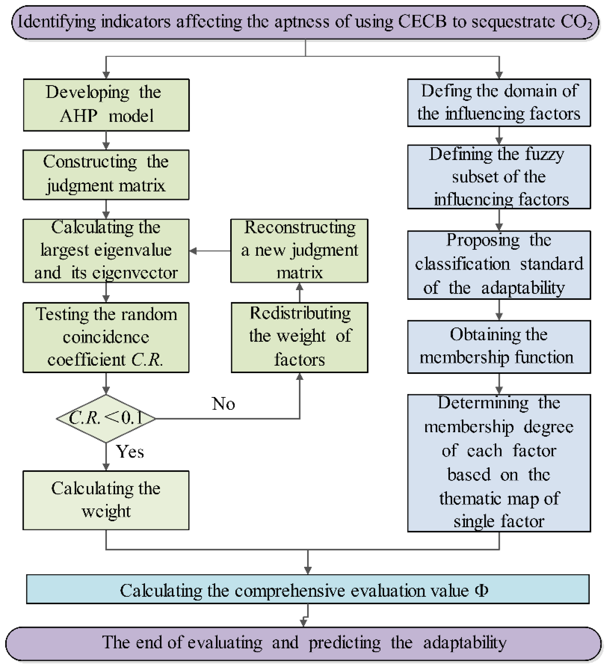
5. Mathematical Modeling and Weight Distribution

5.1. Mathematical Modeling

The AHP-fuzzy comprehensive evaluation method was employed to evaluate the suitability of using CECB to sequestrate CO2. Based on the analysis of the factors influencing the applicability, six sub-factors and nineteen triple-leveled factors were identified and determined. In the AHP model, A represents the overall goal, B denotes the evaluation standard, and C is the sub-standard. The judgment matrix was constructed using this hierarchy to realize the numerical expression and quantification of the appropriateness. The influencing factors were put into a discourse domain U,
U = {u1, u2, u3, u4, u5, u6},
Let V denote the discourse domain of applicability. The grade of adaptability was represented by the comprehensive evaluation value, Φ, which is the membership degree of U in the fuzzy subset V. The fuzzy subset V was defined by Equation (34) [26]:
V = {I, II, III, IV},
The comprehensive evaluation value Φ can be derived via the following equation:
Φ = i = 1 n w i u i ( u i ) ,
where ui(ui) is the membership degree of the i-th influencing factor and wi is the weight of the i-th indicator.
The fuzzy subset V of the adaptability of CO2 sequestration in the CECB mining face can be divided into four grades, as listed in Table 4. The applicability is therefore quantified and embodied by calculating the value Φ.

5.2. Weight Distribution

The 1–9 and its reciprocal scaling method proposed by Thomas. L. Saaty was employed to determine the value of the judgment matrix elements and thus reflect the relative importance of each element. aij denotes the relative importance of the i-th indicator to the j-th indicator. Experts and scholars engaged in CECB mining, cemented backfill development, coal extraction under BRW, and CO2 sequestration were invited to assign the weights of various factors in the AHP model to evaluate the applicability of using CECB to sequestrate CO2 by developing CMFB. The following judgment matrixes were determined according to the relative weight of the experts:
W A ~ B = [ 1 1 / 3 1 / 2 1 1 / 2 2 3 1   2   3 3 / 2   6 2 2 / 3 1   2 1     4 1 1 / 3   1 / 2 1 1 / 2 2 2 2 / 3 1 2 1 4 1 / 2 1 / 6 1 / 4 1 / 2 1 / 4 1 ] . W B 5 ~ C = [ 1 1 / 2 3 2 3 2 2 1 6 4 6 4 1 / 3 1 / 6   1   2 / 3 1 2 / 3 1 / 2 1 / 4 3 / 2   1 3 / 2 1 1 / 3 1 / 6 1 2 / 3 1 2 / 3 1 / 2 1 / 4 3 / 2 1 3 / 2 1 ] W B 1 ~ C = [ 1 1 / 2 1 2   1   2 1 3 / 5 1 ] W B 2 ~ C = [ 1   1 / 2   1 2   1   2 1   1 / 2   1 ] W B 3 ~ C = [ 1     4     2 1 / 4   1   1 / 2 1 / 2   2   1 ] W B 4 ~ C = [ 1 1 / 3 3 1 ] W B 6 ~ C = [ 1 3 1 / 3 1 ]
The roof and floor system whose matrix is W B 1 ~ C was taken as an example. Its maximum eigenvalue is 3.0652, and the corresponding eigenvector W = [0.2461, 0.4923, 0.2616]. Then Formulae (36) and (37) were used for consistency test.
C . I . = ( λ max n ) / ( n 1 ) ,
where C.I. denotes the consistency indicator; λmax denotes the largest eigenvalue; n denotes the number of the factors in the matrix W B 1 ~ C .
C . R . = ( C . I . ) / ( R . I . ) ,
where C.R. is the consistency ratio and R.I. is the average consistency index.
If C.R. ≥ 0.1, the relative weights in the matrix should be reassigned. Otherwise, the weight distribution is reasonable, and the calculation results can be taken as the final results. The C.R. of the matrix is 0.0627, which is much less than 0.1, suggesting the relative weights given by the experts are acceptable.
The weight of the roof and floor system is 0.1037. Therefore, the weight of the three third-level factors in the roof and floor system is 0.0255, 0.0511, and 0.0271, respectively.
The consistency tests of the other six matrices were conducted in the same way and the results are listed in Table 5. After finishing the consistency test, the weight distribution of all the influencing factors were obtained and are listed in Table 6.

6. Generalization and Application of the Prediction Model

The Yu-Shen coal area, covering a total area of 5160 km2, is situated in the north of Yulin City, Shaanxi Province, China. The total in situ coal reserve in this area is greater than 30 billion tons. In the early phase of coal mining, owing to the high-intensity and large-scale mining activities, the water level of the Salawusu Formation aquifer dropped drastically over a large area, and the number of springs and rivers declined sharply. This phenomenon seriously jeopardizes domestic and ecological water use for local residents and the environment. Additionally, the surface buildings, structures, and ecosystem were damaged to a large extent due to mining-caused surface subsidence, forcing the relocation of the villages in the vicinity of the many collieries in the coal area. Backfill mining is thus necessary for the coal area. On the other hand, large amounts of coal-based solid wastes such as fly ash and gangue are produced and accumulated in the process of coal extraction and coal dressing. Meanwhile, the coal burning and consumption in the thermal power plant in the Yu-Shen mining area generates a quantity of CO2 gas to generate electricity. Therefore, the coal area is taken as an instance to predict the suitability of CO2 sequestration using CECB and CMFB. It is noted that the prospective investigation is only a feasibility analysis for the field application of the concept in the future. The concept has not been employed in any colliery in the Yu-Shen mining area.
Prior to employing CECB to sequestrate CO2 by means of developing CMFB in the mining area, the adaptability of this method for various collieries (400 boreholes) is predicted by using the proposed mathematical evaluation model. Subsequently, the thematic map of the contour map of Φ is plotted, to provide a decision basis for the planners and engineers. The primary calculating process of the comprehensive evaluation value Φ of the applicability of using CECB to sequestrate CO2 is shown in Figure 8. First, plotting the thematic map of a single indicator affects the suitability of the concept. Then, determining the membership degree of each factor based on comprehensively analyzing the thematic map and summarizing the relevant literature. Third, based on the weight distribution of each influencing factor listed in Table 6 as well as the membership degree of each factor, calculate the value of Φ by using Equation (35).

6.1. Determination of Membership Degree

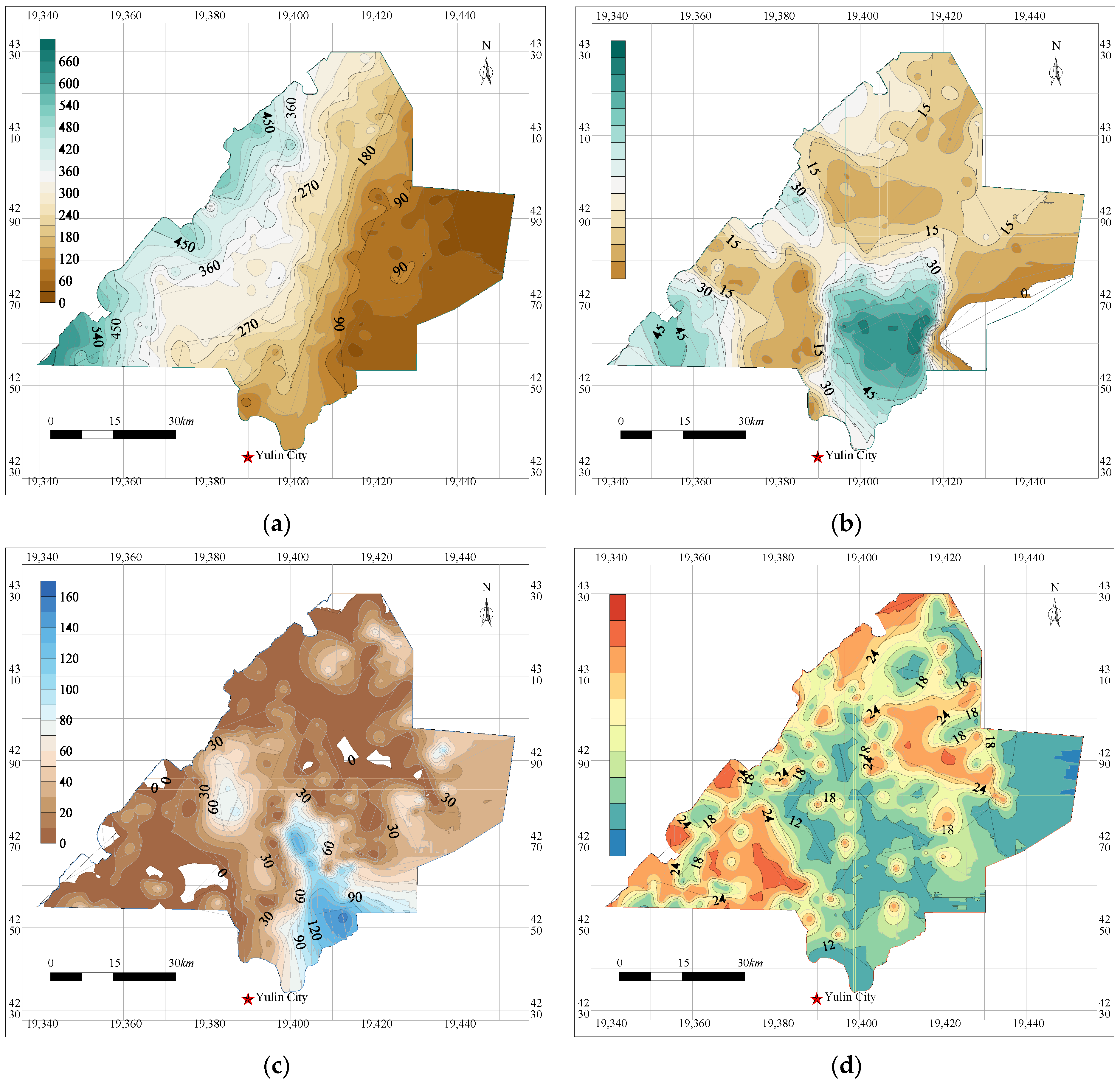
6.1.1. Roof and Floor Conditions in the Yu-Shen Mining Area

According to the borehole data, the basic roof is dominantly off-white and light gray middle-fine grained feldspar sandstone, debris-feldspar, and calcareous sandstone, followed by gray black siltstone. The UCS of the basic roof is more than 80 MPa. The ratio of the thickness of the basic roof to the first-mined coal seam varies greatly, with an average of eight. The immediate floor is primarily composed of sandy mudstone, mudstone, and carbonaceous mudstone, with lenticular marl distributed sporadically. The UCS of the floor ranges from 24 to 66 MPa, with an average of 45 MPa.

6.1.2. Thematic Maps of BWR System

Due to the fragile ecological environment of the whole mining area, the protection level of surface buildings is regarded as grade I. Moreover, there are four types of overlying aquifers in the Yu-Shen mining area, namely, the confined porous bedrock aquifer, the burnt rock phreatic aquifer, and the Salawusu phreatic aquifer, and the unconsolidated porous phreatic aquifer, with increasing elevation. The Salawusu Formation aquifer, featuring a large thickness, shallowly buried depth, and wide distribution, is the main aquifer in the coal area which should be taken into account when predicting the adaptability. Based on the collected borehole data, the contour maps of the distance from the overlying aquifer to the first-mined coal seam and the contour map of the height of the water conductive fractured zone, were drawn by employing the Kriging interpolation method, as shown in Figure 9a,b respectively. The contour map of the aquifuge (clay and red soil), whose water-resisting index equals 1 is shown in Figure 9c. The bedrock of the entire Yu-Shen mining area is composed of sandstone, mudstone, and sandy mudstone, and the water-resisting index of the bedrock is 0.4. Using Equation (3), the thicknesses of the protection zone of 400 boreholes in the Yu-Shen mining area were obtained, and the contour map was plotted by using Surfer software, as shown in Figure 9d. Furthermore, the areas of high water abundance of the Sarawusu Formation aquifer cover a total area of 504 km2, which represents 10 percent of the entire Yu-Shen mining area. The total acreage of the moderate and low water-rich regions is 1911 km2 and 1919 km2, respectively, accounting for approximately 37% of the mining area. The zoning map of the water-richness of the overlying aquifer is shown in Figure 10.

6.1.3. Thematic Map of Geological Structures System

The geological exploitation results show that there are seven faults in the entire Yu-Shen coal area and the geological structure is simple. The fault distribution and the fault strength are shown in Figure 11. Generally, we tend to agree that there are no obvious folds or collapse column structures in the entire coal area.

6.1.4. Membership Degree of Mining Block System

The shape of the CECB mining panel is thought of as quadrangular, so the irregular rate is 1. According to the preliminary colliery planning before production, the annual output of a working face is usually more than 400,000 tons.

6.1.5. Thematic Maps of Coal Seam System

The buried depth of the first-mined coal seam varies from 0 to 650 m, with a thickness ranging from 0 to 12 m and the dip angle varying from 1° to 3°. The contour maps of the buried depth and the thickness of the first-mined coal seam were plotted, respectively, as shown in Figure 12a,b. The coal seam thickness shows narrow variation in the CECB mining panel, and the variation coefficient is, therefore, less than 30%. The first-mined coal seam is generally free of gangue. Only a small part of the coal seam contains 1 or 2 layers of gangue, indicating that the coefficient of the dirt band is less than 10%. The first-mined coal seam belongs to long-flame coal or non-caking coal, and the Proctor coefficient is from 2 to 2.5.

6.1.6. Thematic Map of CMFB System

Taking CMFB with a curing time of 56 d and a fly ash content of 75% as an example, its UCS is 7.499 MPa and its elastic modulus is 1.5 GPa. According to the coal seam burial depth of different boreholes, the compressibility of CMFB corresponding to 400 boreholes is calculated by using Equation (31) and the contour map is drawn by the Kriging interpolation method, as shown in Figure 13.

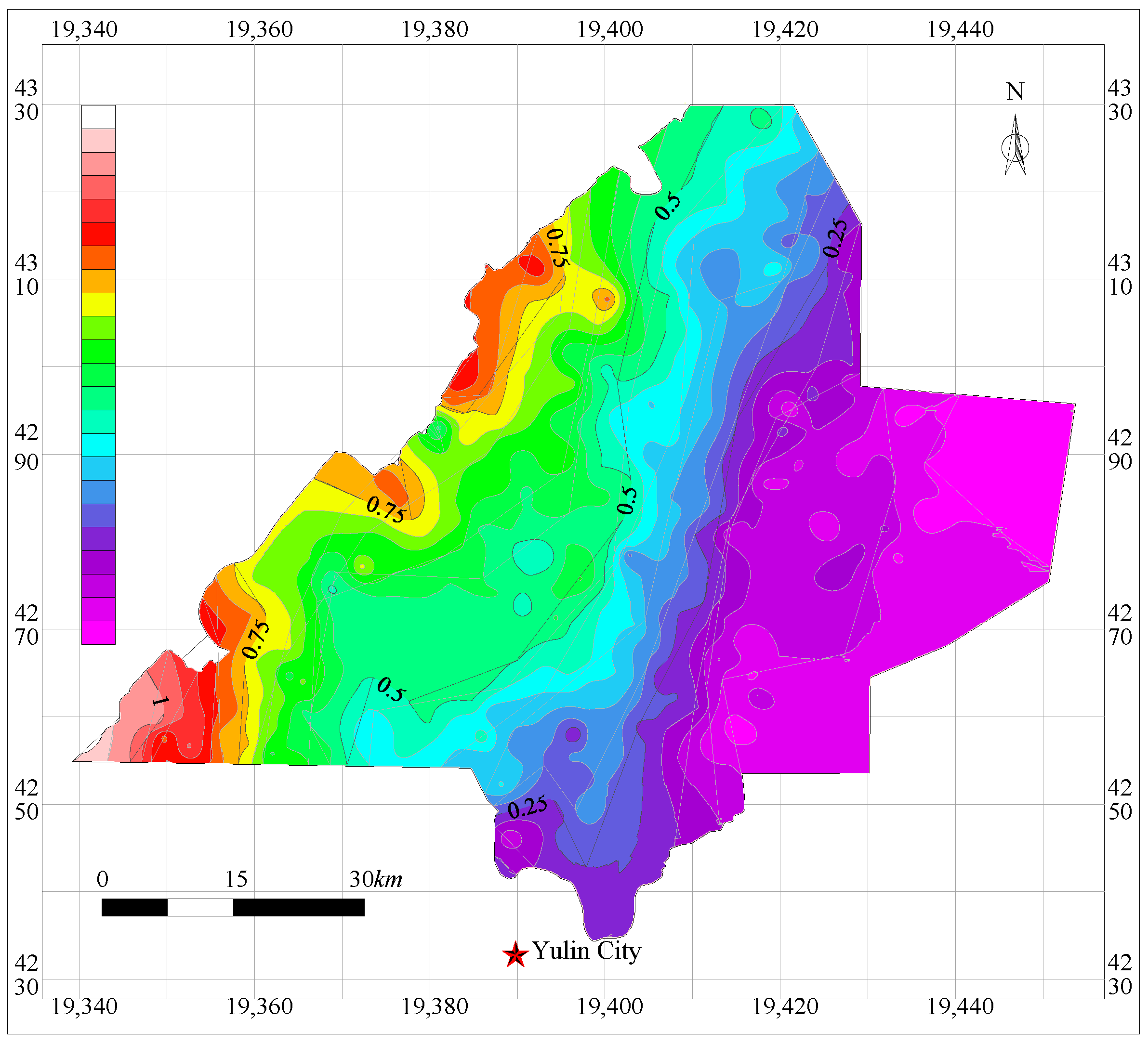
6.2. Prediction Results of the Suitability of Using CECB to Sequestrate CO2

Based on the calculation results of the comprehensive evaluation value Φ of 400 boreholes, the contour map of the appropriateness degree Φ in the Yu-Shen mining area was plotted using the Kriging method, as shown in Figure 14.
The grades of the adaptability of various boreholes in the northwest area are generally higher than those of the southeast overall. There are three grade I regions, all of which are geographically fragmented in the northwest, southwest, and eastern areas of the Yu-Shen coal area. Good coal seam occurrence and its roof and floor conditions, large distance from the aquifer and coal seam, and high water-richness are typical features of these regions. These three areas can employ the CECB mining method to sequestrate CO2 directly without adopting other countermeasures, and building protection, water body preservation, and conservation can be realized. The appropriateness of the western border and the middle and northeast parts of the mining area belong to grade II. The collieries in these regions can sequestrate CO2 utilizing the CECB method by taking minor supplementary measurements, and coordinated development among village protection, water body preservation, CO2 sequestration, and treatment of coal-based solid waste can be obtained.
The regions, with the degree of appropriateness ranging between grade III and grade IV, are geologically dispersed in the vicinity of the area where the geological structures exist while there is no Salawusu Formation aquifer occurrence. For collieries whose suitability belongs to grade III and grade IV, it is not suitable for the CECB method to extract coal resources and sequestrate CO2 by means of CMFB under BRW since the economic and ecological benefits are too minor or even lower than the investment. The evaluation results of our research are consistent with other evaluation methods, indicating the prediction model is scientific, reasonable, and reliable.

7. Discussion

(1) In this paper, a novel method for CO2 sequestration was proposed by developing CMFB and injecting it into the mined-out MRs of CECB mining under BRW. The adaptability of this concept is investigated, to generalize and apply this method in the future. For common CO2 sequestration methods, the supercritical CO2 is injected into the subsurface structures such as abandoned oil reservoirs, deep saline aquifers, un-minable coal seams and so forth [55,56,57]. However, CO2 may leak and escape into the air again while being confronted with large disturbances of the overlying strata. Therefore, developing CMFB and introducing it into the mined-out area by the CECB mining method is the most effective approach to sequestrate CO2. As far as economic benefits are concerned, the investment in our method is far less than the conventional methods for CO2 sequestration. What is known to us all is that special facilities such as pressurizing equipment which pressurizes CO2 gas to turn it into supercritical CO2 are necessary for conventional CO2 storage. The extra apparatus indicate high cost and the economic benefits are therefore limited. In contrast, the CECB is usually employed to extract the coal body under BRW [58,59]. The filling body here is necessary and the CMFB is developed only by adhering CO2 gas to the fresh slurry of the filling body. The CMFB share the filling transportation pipeline and other facilities with traditional cement filling materials. The extra investment for installing the tank to store the CO2 gas is too low to ignore. As illustrated in the paper, the process of developing CMFB is similar to the common filling body development. The reaction rate of CO2 gas and fly ash, and coal-based solid wastes, at ambient temperature and pressure, is rapid by adding catalyzers such as silicate additives, which makes it feasible for the large-scale industrialization of CO2 sequestration. The time cost of CO2 sequestration using CMFB and CECB is of great minority. To sum up, compared with conventional CO2 storage, the method proposed in our paper has advantages in both economic benefits and time cost over other traditional methods for CO2 sequestration.
(2) The CO2 mineralization process with solid wastes should be carried out continuously in a space where fresh slurry cannot seep out. Meanwhile, the MR of the CECB mining method can tackle this problem easily since it features excellent leakage-isolated properties. In addition, the mining disturbance at the storage site of CMFB should be mitigated as much as possible since the excessive disturbance may cause the instability of CMFB. The span of MR is narrower than that of longwall mining, contributing to the restricted mined-out space and thus maintaining the stability of the mining stope. It is noted that this paper is only a preliminary study of using CECB to sequestrate CO2 by means of developing CMFB and injecting it into the mined-out area. In the process of field practice of this method, there are many problems waiting to be resolved, such as large-scale capture of CO2 gas, CMFB transportation, and the weakening mechanism of CMFB soaked with water.
(3) To avoid the mutual restrictions between extracting and filling, these two operations are separated into two different positions in the CECB mining method. This is essentially different from the operations of traditional longwall backfill mining. The CMFB can maintain stability before reaching its designed strength owing to the limited exposure of each MR, which leads to restricted roof subsidence. It is necessary to investigate the suitability of using other backfill mining methods to sequestrate CO2 by developing CMFB. For instance, the mining processes of longwall backfill mining are essentially different from those of CECB mining. The extracting and backfill operations are not totally separated from each other, giving rise to mutual influence, and thus it is unsuitable to be employed to sequestrate CO2. In addition, the CMFB in CECB mining stays in three-dimensional stress, while the CMFB in longwall backfill mining is in uniaxial stress. This is apt to result in CMFB instability since its three-dimensional strength is far greater than that of the uniaxial one. Furthermore, if the slurry of CMFB is injected into the flexible bags in longwall backfill mining, they may suffer from instability owing to weathering caused by torn flexible materials.
(4) The mathematical model for predicting the adaptability of using CECB to sequestrate CO2 can provide references to the generalization and application of this method. In future research, the model will be employed in other mining areas that are still in preparation or exploration and have not yet been put into production. For instance, it can be utilized to evaluate the adaptability of the Ningdong, Shendong, and Huanglong mining areas, since they share similar engineering and hydrogeological conditions with the Yu-Shen mining area. Whereas it is inappropriate for the model to be applied in the Xinjiang mining area, owing to its extremely thick coal seam (>100 m) and totally different geological and engineering conditions. To accurately predict the suitability and hence promote its application in a larger area, the reidentification of influencing factors and the redistribution of weights in the prediction model should be carried out by the scholars engaged in coal extraction in the Xinjiang coal area.
(5) To analyze a complex problem, the AHP-fuzzy comprehensive evaluation method has been widely used. Generally, this research usually takes the average membership degree of one influencing factor in various regions to represent the whole evaluation object, indicating the inaccuracy and irrationality of the prediction results. The innovation point of our research is that we evaluated the aptness of using CECB to sequestrate CO2 in the entire mining area and plotted the zoning map of the adaptability grade based on the evaluation results of 400 drillholes in various locations in the Yu-Shen mining area. The research findings can offer a prospective reference for the generalization and application of employing CECB to realize CO2 sequestration in the future.

8. Conclusions

The conclusions drawn from the research are as follows:
(1) A novel concept of CO2 sequestration by developing CMFB together with injecting it into the mined-out area of CECB mining is proposed. Currently, the filling materials are primarily cemented backfill, solid backfill (crushed gangue), and high-water content backfill. However, none of these aforementioned filling materials takes CO2 sequestration into consideration. In this paper, industrialized CO2 sequestration is incorporated into the framework of green mining and the “trinity” of low-carbon, sustainable, and ecologically protective mining is proposed. This is, large-scale and permanent CO2 sequestration, harmless treatment of coal-based solid wastes, and coal extraction under BRW, which is innovative compared with the previous research;
(2) The CMFB was developed by making CO2 react with coal-based solid wastes at ambient temperature and pressure. Fly ash was employed as aggregate, while CO2 gas, silicate additives, and cement were taken as accessories. The UCS of CMFB with various curing times and different fly ash contents was tested indoors. The results show that, as the fly ash content increases, the UCS ascends first and then decreases, reaching the peak when the fly ash content is 75%. Furthermore, the Young’s modulus of the CMFBs of various setting times and material ratios is determined, so as to determine the membership degrees of the two indicators in the CMFB system;
(3) The AHP-fuzzy comprehensive evaluation method was employed to construct a triple-leveled hierarchy model for predicting the adaptability of using CECB to sequester CO2. Six sub-indicators and nineteen tertiary indicators were chosen as the factors, and the weight distribution and membership functions of the influencing factors were analyzed and determined. The results show that, among the secondary influence indicators, the BWR system, with a weight of 0.3262, is the most important one, followed by the geological structures system and the coal seam system, whose weights are both 0.2073. The distance from the overlying aquifer to the coal seam, with a weight of 0.1631, is the critical tertiary indicator;
(4) The prediction model was generalized and employed to evaluate its applicability in the Yu-Shen mining area. The thematic map of a single factor was drawn to determine the membership degree of each indicator. Then, the adaptability of 400 boreholes in the entire coal area was calculated, and the Kriging interpolation method was utilized to plot the zoning map of suitability in the whole mining area. The prediction results can provide a theoretical basis and practical reference for the field application of developing CMFB and using CECB to sequestrate CO2 gas in the future.

Author Contributions

Conceptualization, Y.X. and L.M.; methodology, Y.X.; formal analysis, I.N.; investigation, Y.W. and L.H.; resources, L.M.; data curation, J.Z.; writing—original draft preparation, Y.X.; writing—review and editing, Y.X. and L.M.; supervision, L.M.; project administration, L.M.; funding acquisition, L.M. All authors have read and agreed to the published version of the manuscript.

Funding

This paper was funded by the National Natural Science Foundation of China (51874280) and the Fundamental Research Funds for the Central Universities (2021ZDPY0211).

Data Availability Statement

Not applicable.

Acknowledgments

This paper was supported by the National Natural Science Foundation of China (51874280) and the Fundamental Research Funds for the Central Universities (2021ZDPY0211).

Conflicts of Interest

The authors declare no conflict of interest.

Abbreviations

CMFBCO2 mineralized filling body
MRsmining roadways
CECBcontinuous extraction and continuous backfill
BRWbuildings, railways, and water bodies
AHPanalytic hierarchy process
UCSuniaxial compressive strength
MRsmining roadways
FAfly ash
CMCement
FA55the ratio of the fly ash to the total of the fly ash and the cement is 55%
FA65the ratio of the fly ash to the total of the fly ash and the cement is 65%
FA75the ratio of the fly ash to the total of the fly ash and the cement is 75%
FA85the ratio of the fly ash to the total of the fly ash and the cement is 85%

References

  1. Zhang, D.; Fan, G.; Ma, L.; Wang, X. Aquifer protection during longwall mining of shallow coal seams: A case study in the Shendong Coalfield of China. Int. J. Coal Geol. 2011, 86, 190–196. [Google Scholar] [CrossRef]
  2. Fan, L.; Ma, L.; Yu, Y.; Wang, S.; Xu, Y. Water-conserving mining influencing factors identification and weight determination in northwest China. Int. J. Coal Sci. Technol. 2019, 6, 95–101. [Google Scholar] [CrossRef] [Green Version]
  3. Fan, L.; Ma, X. A review on investigation of water-preserved coal mining in western China. Int. J. Coal Sci. Technol. 2018, 5, 411–416. [Google Scholar] [CrossRef] [Green Version]
  4. Ma, L.; Jin, Z.; Liang, J.; Sun, H.; Zhang, D.; Li, P. Simulation of water resource loss in short-distance coal seams disturbed by repeated mining. Environ. Earth Sci. 2015, 74, 5653–5662. [Google Scholar] [CrossRef]
  5. Wang, A.; Ma, L.; Wang, Z.; Zhang, D.; Li, K.; Zhang, Y.; Yi, X. Soil and water conservation in mining area based on ground surface subsidence control: Development of a high-water swelling material and its application in backfilling mining. Environ. Earth Sci. 2016, 75, 779. [Google Scholar] [CrossRef]
  6. Wang, S.; Ma, L. Characteristics and Control of Mining Induced Fractures above Longwall Mines Using Backfilling. Energies 2019, 12, 4604. [Google Scholar] [CrossRef] [Green Version]
  7. Xu, Y.; Ma, L.; Yu, Y. Water Preservation and Conservation above Coal Mines Using an Innovative Approach: A Case Study. Energies 2020, 13, 2818. [Google Scholar] [CrossRef]
  8. Xu, Y.; Ma, L.; Khan, N.M. Prediction and Maintenance of Water Resources Carrying Capacity in Mining Area—A Case Study in the Yu-Shen Mining Area. Sustainability 2020, 12, 7782. [Google Scholar] [CrossRef]
  9. Sun, K.; Fan, L.; Xia, Y.; Li, C.; Chen, J.; Gao, S.; Wu, B.; Peng, J.; Ji, Y. Impact of coal mining on groundwater of Luohe Formation in Binchang mining area. Int. J. Coal Sci. Technol. 2020, 8, 88–102. [Google Scholar] [CrossRef]
  10. Li, L.; Li, F.M.; Zhang, Y.; Yang, D.M.; Liu, X. Formation mechanism and height calculation of the caved zone and water-conducting fracture zone in solid backfill mining. Int. J. Coal Sci. Technol. 2020, 7, 208–215. [Google Scholar] [CrossRef] [Green Version]
  11. Hou, E.; Wen, Q.; Ye, Z.; Chen, W.; Wei, J. Height prediction of water-flowing fracture zone with a genetic-algorithm support-vector-machine method. Int. J. Coal Sci. Technol. 2020, 7, 740–751. [Google Scholar] [CrossRef]
  12. Xu, Y. Study on “Five Maps, Three zones and Two Zoning Plans” Water Conservation Mining Method in Yu-Shen Mining Area. Master’s Thesis, China University of Mining Science & Technology, Xuzhou, China, 2019. [Google Scholar]
  13. Xu, Y.; Ma, L.; Ngo, I.; Zhai, J. Prediction of the Height of Water-Conductive Fractured Zone under Continuous Extraction and Partial Backfill Mining Method—A Case Study. Sustainability 2022, 14, 6582. [Google Scholar] [CrossRef]
  14. Lian, X.; Hu, H.; Li, T.; Hu, D. Main geological and mining factors affecting ground cracks induced by underground coal mining in Shanxi Province, China. Int. J. Coal Sci. Technol. 2020, 7, 362–370. [Google Scholar] [CrossRef] [Green Version]
  15. Brent, G.F.; Allen, D.J.; Eichler, B.R.; Petrie, J.G.; Mann, J.P.; Haynes, B.S. Mineral Carbonation as the Core of an Industrial Symbiosis for Energy-Intensive Minerals Conversion. J. Ind. Ecol. 2012, 16, 94–104. [Google Scholar] [CrossRef]
  16. Olajire, A.A. A review of mineral carbonation technology in sequestration of CO2. J. Pet. Sci. Eng. 2013, 109, 364–392. [Google Scholar] [CrossRef]
  17. Thanh, H.V.; Yasin, Q.; Al-Mudhafar, W.J.; Lee, K.-K. Knowledge-based machine learning techniques for accurate prediction of CO2 storage performance in underground saline aquifers. Appl. Energy 2022, 314, 118985. [Google Scholar] [CrossRef]
  18. Kim, Y.; Jang, H.; Kim, J.; Lee, J. Prediction of storage efficiency on CO2 sequestration in deep saline aquifers using artificial neural network. Appl. Energy 2017, 185, 916–928. [Google Scholar] [CrossRef]
  19. Ahmadi, M.A.; Kashiwao, T.; Rozyn, J.; Bahadori, A. Accurate prediction of properties of carbon dioxide for carbon capture and sequestration operations. Pet. Sci. Technol. 2016, 34, 97–103. [Google Scholar] [CrossRef]
  20. Thanh, H.V.; Sugai, Y.; Nguele, R.; Sasaki, K. Integrated workflow in 3D geological model construction for evaluation of CO2 storage capacity of a fractured basement reservoir in Cuu Long Basin, Vietnam. Int. J. Greenh. Gas Control 2019, 90, 102826. [Google Scholar] [CrossRef]
  21. He, L.; Shen, P.; Liao, X.; Gao, Q.; Wang, C.; Liang, F. Study on CO2 EOR and its geological sequestration potential in oil field around Yulin city. J. Petrol. Sci. Eng. 2015, 134, 199–204. [Google Scholar]
  22. Pratama, E.; Ismail, M.S.; Ridha, S. Identification of coal seams suitability for carbon dioxide sequestration with enhanced coalbed methane recovery: A case study in South Sumatera Basin, Indonesia. Clean Technol. Environ. Policy 2017, 20, 581–587. [Google Scholar] [CrossRef]
  23. Vo, T.H.; Sugai, Y.; Sasaki, K. Application of artificial neural network for predicting the performance of CO2 enhanced oil recovery and storage in residual oil zones. Sci. Rep. 2020, 10, 18204. [Google Scholar]
  24. Deveci, M.; Demirel, N.; John, R.; Ozcan, E. Fuzzy multi-criteria decision making for carbon dioxide geological storage in Turkey. J. Nat. Gas Sci. Eng. 2015, 27, 692–705. [Google Scholar] [CrossRef] [Green Version]
  25. Ji, L.; Yu, H.; Yu, B.; Zhang, R.; French, D.; Grigore, M.; Wang, X.; Chen, Z.; Zhao, S. Insights into Carbonation Kinetics of Fly Ash from Victorian Lignite for CO2 Sequestration. Energy Fuels 2018, 32, 4569–4578. [Google Scholar] [CrossRef]
  26. Chen, T.; Bai, M.; Gao, X. Carbonation curing of cement mortars incorporating carbonated fly ash for performance improvement and CO2 sequestration. J. CO2 Util. 2021, 51, 101633. [Google Scholar] [CrossRef]
  27. Xu, Y.; Ma, L.; Ngo, I.; Zhai, J. Continuous Extraction and Continuous Backfill Mining Method Using Carbon Dioxide Mineralized Filling Body to Preserve Shallow Water in Northwest China. Energies 2022, 15, 3614. [Google Scholar] [CrossRef]
  28. Ajayi, S.A.; Ma, L.; Spearing, A.J.S. Ground Stress Analysis and Automation of Workface in Continuous Mining Continuous Backfill Operation. Minerals 2022, 12, 754. [Google Scholar] [CrossRef]
  29. Ma, L.; Zhang, D.; Wang, S.; Xie, Y.; Yu, Y. Water-preserved mining with the method named “backfilling while mining”. J. Chin. Coal Soc. 2018, 43, 62–69. [Google Scholar]
  30. Ma, L.; Jin, Z.; Liu, W.; Zhang, D.; Zhang, Y. Wongawilli roadway backfilling coal mining method—A case study in Wangtaipu coal mine. Int. J. Oil Gas Coal Technol. 2019, 20, 342–359. [Google Scholar] [CrossRef]
  31. Yu, Y.; Ma, L. Application of Roadway Backfill Mining in Water-Conservation Coal Mining: A Case Study in Northern Shaanxi, China. Sustainability 2019, 11, 3719. [Google Scholar] [CrossRef] [Green Version]
  32. Yu, Y.; Ma, L.; Zhang, D. Characteristics of Roof Ground Subsidence While Applying a Continuous Excavation Continuous Backfill Method in Longwall Mining. Energies 2019, 13, 95. [Google Scholar] [CrossRef] [Green Version]
  33. Ross, C.; Conover, D.; Baine, J. Highwall mining of thick, steeply dipping coal–a case study in geotechnical design and recovery optimization. Int. J. Min. Sci. Technol. 2019, 29, 777–780. [Google Scholar] [CrossRef]
  34. Liu, J.; Sui, W.; Zhao, Q. Environmentally sustainable mining: A case study of intermittent cut-and-fill mining under sand aquifers. Environ. Earth Sci. 2017, 76, 562. [Google Scholar] [CrossRef] [Green Version]
  35. Zhang, J.; Sun, Q.; Zhou, N.; Haiqiang, J.; Germain, D.; Abro, S. Research and application of roadway backfill coal mining technology in western coal mining area. Arab. J. Geosci. 2016, 9, 558. [Google Scholar] [CrossRef]
  36. Spearing, A.; Zhang, J.; Ma, L. A new automated, safe, environmentally sustainable, and high extraction soft-rock underground mining method. J. S. Afr. Inst. Min. Metall. 2021, 121, 89–96. [Google Scholar] [CrossRef]
  37. Liu, Y.; Eckert, C.M.; Earl, C. A review of fuzzy AHP methods for decision-making with subjective judgements. Expert Syst. Appl. 2020, 161, 113738. [Google Scholar] [CrossRef]
  38. Saaty, T.L.; Beltran; Miguel, H. Architectural Design by the Analytic Hierarchy Process. 1980. Available online: http://papers.cumincad.org/cgi-bin/works/2015%20+dave=2:/Show?c380 (accessed on 26 May 2022).
  39. Saaty, T.L. The Application of Analytic Hierarchy Process in Resource Allocation, Management and Conflict Analysis; Coal Industry Press: Beijing, China, 1988; Volume 334. [Google Scholar]
  40. Yu, H.; Gui, H.; Zhao, H.; Wang, M.; Li, J.; Fang, H.; Jiang, Y.; Zhang, Y. Hydrochemical characteristics and water quality evaluation of shallow groundwater in Suxian mining area, Huaibei coalfield, China. Int. J. Coal Sci. Technol. 2020, 7, 825–835. [Google Scholar] [CrossRef]
  41. Yu, H.; Jia, H.; Liu, S.; Liu, Z.; Li, B. Macro and micro grouting process and the influence mechanism of cracks in soft coal seam. Int. J. Coal Sci. Technol. 2021, 8, 969–982. [Google Scholar] [CrossRef]
  42. Wang, J.; Yang, J.; Wu, F.; Hu, T.; al Faisal, S. Analysis of fracture mechanism for surrounding rock hole based on water-filled blasting. Int. J. Coal Sci. Technol. 2020, 7, 704–713. [Google Scholar] [CrossRef]
  43. Gao, R.; Kuang, T.; Zhang, Y.; Zhang, W.; Quan, C. Controlling mine pressure by subjecting high-level hard rock strata to ground fracturing. Int. J. Coal Sci. Technol. 2021, 8, 1336–1350. [Google Scholar] [CrossRef]
  44. Li, C.; Guo, D.; Zhang, Y.; An, C. Compound-mode crack propagation law of PMMA semicircular-arch roadway specimens under impact loading. Int. J. Coal Sci. Technol. 2021, 8, 1302–1315. [Google Scholar] [CrossRef]
  45. Wu, R.; Zhang, P.; Kulatilake, P.H.S.W.; Luo, H.; He, Q. Stress and deformation analysis of gob-side pre-backfill driving procedure of longwall mining: A case study. Int. J. Coal Sci. Technol. 2021, 8, 1351–1370. [Google Scholar] [CrossRef]
  46. Lou, J.; Gao, F.; Yang, J.; Ren, Y.; Li, J.; Wang, X.; Yang, L. Characteristics of evolution of mining-induced stress field in the longwall panel: Insights from physical modeling. Int. J. Coal Sci. Technol. 2021, 8, 938–955. [Google Scholar] [CrossRef]
  47. André, V. Various phases in surface movements linked to deep coal longwall mining: From start-up till the period after closure. Int. J. Coal Sci. Technol. 2021, 8, 412–426. [Google Scholar]
  48. Chi, X.; Yang, K.; Wei, Z. Breaking and mining-induced stress evolution of overlying strata in the working face of a steeply dipping coal seam. Int. J. Coal Sci. Technol. 2021, 8, 614–625. [Google Scholar] [CrossRef]
  49. Yanli, H.; Jixiong, Z.; Baifu, A.; Qiang, Z. Overlying strata movement law in fully mechanized coal mining and backfilling longwall face by similar physical simulation. J. Min. Sci. 2011, 47, 618–627. [Google Scholar] [CrossRef]
  50. Huang, Y.; Li, J.; Ma, D.; Gao, H.; Guo, Y.; Ouyang, S. Triaxial compression behaviour of gangue solid wastes under effects of particle size and confining pressure. Sci. Total Environ. 2019, 693, 133607. [Google Scholar] [CrossRef]
  51. Huang, Y.; Zhang, J.; Zhang, Q.; Nie, S. Backfilling technology of substituting waste and fly ash for coal underground in China coal mining area. Environ. Eng. Manag. J. 2011, 10, 769–775. [Google Scholar] [CrossRef]
  52. Huang, Y.; Li, J.; Song, T.; Kong, G.; Li, M. Analysis on Filling Ratio and Shield Supporting Pressure for Overburden Movement Control in Coal Mining with Compacted Backfilling. Energies 2016, 10, 31. [Google Scholar] [CrossRef] [Green Version]
  53. Li, J.; Huang, Y.; Li, W.; Guo, Y.; Ouyang, S.; Cao, G. Study on dynamic adsorption characteristics of broken coal gangue to heavy metal ions under leaching condition and its cleaner mechanism to mine water. J. Clean. Prod. 2021, 329, 129756. [Google Scholar] [CrossRef]
  54. Baidu. Available online: https://wenku.baidu.com/view/5527082a15fc700abb68a98271fe910ef12dae17.html (accessed on 6 July 2022).
  55. Li, Q. The view of technological innovation in coal industry under the vision of carbon neutralization. Int. J. Coal Sci. Technol. 2021, 8, 1197–1207. [Google Scholar] [CrossRef]
  56. Hu, G.; Liu, G.; Wu, D.; Zhang, W.; Fu, B. Method for evaluation of the cleanliness grade of coal resources in the Huainan Coalfield, Anhui, China: A case study. Int. J. Coal Sci. Technol. 2021, 8, 534–546. [Google Scholar] [CrossRef]
  57. Li, C.; Zheng, L.; Jiang, C.; Chen, X.; Ding, S. Characteristics of leaching of heavy metals from low-sulfur coal gangue under different conditions. Int. J. Coal Sci. Technol. 2021, 8, 780–789. [Google Scholar] [CrossRef]
  58. Wang, X.J.; Wei, B.; Huang, X.; Fan, M.H.; Wang, Y.G.; Chen, X.L. Enhanced near-zero-CO2-emission chemicals-oriented oil production from coal with inherent CO2 recycling: Part I—PRB coal fast pyrolysis coupled with CO2/CH4 reforming. Int. J. Coal Sci. Technol. 2020, 7, 433–443. [Google Scholar] [CrossRef]
  59. Zhu, T.; Wang, R.; Yi, N.; Niu, W.; Wang, L.; Xue, Z. CO2 and SO2 emission characteristics of the whole process industry chain of coal processing and utilization in China. Int. J. Coal Sci. Technol. 2020, 7, 19–25. [Google Scholar] [CrossRef] [Green Version]
Figure 1. Three-dimensional schematic diagram of using CECB mining method to sequestrate CO2.
Minerals 12 00936 g001
Figure 2. Schematic map of the mining process of CECB. (a) The layout of MRs; (b) MRs in the 1st mining phase have been excavated and filled; (c) MRs in the 2nd mining phase have been excavated and filled; (d) MRs in the 3rd mining phase have been excavated and filled; (e) MRs in the 4th mining phase have been excavated and filled.
Minerals 12 00936 g002
Figure 3. The process of preparing the CMFB specimens and the mechanical tests. (ac): weighing and mixing of aggregate and auxiliary materials (df): development of fresh slurry of CMFB. (go): dimension calibration and mechanical test of CMFB samples.
Minerals 12 00936 g003
Figure 4. The chemical reaction between CMFB slurry and CO2 is carried out under stirring.
Minerals 12 00936 g004
Figure 5. The UCS of CMFB with various fly ash contents and curing times. (a) various fly ash contents; (b) various curing times.
Minerals 12 00936 g005
Figure 6. The elastic modulus of CMFB with a curing time of 56 d.
Minerals 12 00936 g006
Figure 7. The hierarchy structure for evaluating the suitability of using CECB to sequestrate CO2.
Minerals 12 00936 g007
Figure 8. Process for evaluating and predicting the adaptability of using CECB to sequestrate CO2.
Minerals 12 00936 g008
Figure 9. Thematic maps of the BRW system. (a) contour map of the distance from the overlying aquifer to the first-mined coal seam; (b) contour map of the height of the water conducting fractured zone; (c) contour map of the thickness of the aquifuge; (d) contour map of the thickness of the protective zone.
Minerals 12 00936 g009
Figure 10. Zoning map of the water-richness of the overlying Salawusu Formation aquifer.
Minerals 12 00936 g010
Figure 11. Distribution of the seven faults and the fault strength in the Yu-Shen mining area.
Minerals 12 00936 g011
Figure 12. Thematic maps of the coal seam system. (a) contour map of the buried depth of the first-mined coal seam; (b) contour map of the thickness of the first-mined coal seam.
Minerals 12 00936 g012
Figure 13. Contour map of the compression rate (×102) of CMFB in the Yu-Shen coal area.
Minerals 12 00936 g013
Figure 14. Contour map of the appropriateness of CO2 sequestration using CECB and CMFB in the Yu-Shen coal area.
Minerals 12 00936 g014
Table 1. The testing schemes of various material ratios and setting times of CMFB.
SchemesProportion of Solid Mass (70 wt%)Ratio of
FA * to CM *
Proportion of Liquid Mass
(30 wt%)
CO2 GasSetting Time
Fly AshCementWaterSilicate Additives
FA55554511:990 wt%10%20 min3/7/14/28/56
FA65653513:790 wt%10%20 min3/7/14/28/56
FA75752515:590 wt%10%20 min3/7/14/28/56
FA85851517:390 wt%10%20 min3/7/14/28/56
* FA represents the fly ash and CM refers to the cement.
Table 2. State classification criteria of the buildings damage grade [12,49].
GradeHorizontal Deformation (mm/m)Curvature (mm/m2)Tilt (mm/m)
≤2.0≤0.2≤3.0
≤4.0≤0.4≤6.0
≤6.0≤0.6≤10.0
>6.0>0.6>10.0
Table 3. Classification standard of water abundance of overlying aquifer [12].
Grade of Water Yield PropertyUniform Drawdown Unit Flow (L·s−1·m−1)
High occurrenceq > 5.0
Medium occurrence5.0 ≥ q ≥0.1
Low occurrenceq > 0.1
Table 4. Classification standard for predicting the adaptability of using CECB to sequestrate CO2.
GradeAdaptabilityValue of ΦRemark
Good1.0 > Φ > 0.9The method can be absolutely applied in the colliery and good ecological, social, and economic benefits can be obtained.
Moderate0.9 ≥ Φ > 0.8The coal mine can utilize CECB to sequestrate CO2 by taking minor supplementary measurements, and the benefits are still considerable.
Slightly poor0.8 ≥ Φ > 0.7The method is not totally appropriate for the colliery due to the complex engineering and hydrogeological conditions. Several countermeasures are necessary, and fewer profits can be made.
Poor0.7 ≥ Φ > 0.6Due to the extremely adverse conditions, the CECB is totally unsuitable for CO2 sequestration no matter what countermeasures will be taken. Although the colliery can extract a part of the coal resources and store small amounts of CO2 gas using the CECB mining method, the filling scale cannot meet the requirements. The investment is far greater than the economic and environmental benefits, and thus the profits cannot meet the disbursements.
Table 5. Results of consistency test of the experts’ scores.
MatrixSort VectorλmaxC.I.R.I.C.R.
A~B[0.1037, 0.3262, 0.2073, 0.1037, 0.2073, 0.0518]6.05490.01091.260.0087
B1~C[0.2461, 0.4923, 0.2616]3.06520.03260.520.0627
B2~C[0.2500, 0.5000, 0.2500]3.000000.520
B3~C[0.5714, 0.1429, 0.2857]3.000000.520
B4~C[0.2500, 0.7500]2.0000000
B5~C[0.2143, 0.4286, 0.0714, 0.1071, 0.0714, 0.1072]6.000101.260
B6~C[0.7500, 0.2500]2.0000000
Table 6. Weight distribution of different influencing factors of CECB adaptability.
Weights of Layer BWeights of Layer C
Roof and floor B1
0.1037
The strength of the basic roof C1
0.0255
The ratio of the main roof thickness to the coal seam thickness C2
0.0511
The strength of the immediate floor C3
0.0271
BWR B2
0.3262
The required protection grade of surface buildings C4
0.0816
The distance from the coal seam to the aquifer C5
0.1631
Water yield property of the aquifer C6
0.0816
Geological structures B3
0.2073
The characteristics of the fault C7
0.1185
The fold complexity coefficient C8
0.0296
The strength index of the collapsed pole C9
0.0592
Mining block B4
0.1037
Irregularity degree of the mining panel C10
0.0259
Coal reserves of the mining panel C11
0.0778
Coal seam B5
0.2073
Buried depth of the coal seam C12
0.0443
Thickness of the coal seam C13
0.0888
Variation coefficient of the thickness of the coal seam C14
0.0148
The dip angel of the coal seam C15
0.0222
The coefficient of the dirt band C16
0.0148
The strength of the coal body C17
0.0222
CMFB B6
0.0518
The strength of the CMFB C18
0.0389
The compression rate of the CMFB C19
0.0129
Total weights of layer B
1.0000
Total weights of layer C
1.0000
Publisher’s Note: MDPI stays neutral with regard to jurisdictional claims in published maps and institutional affiliations.

