Article

Study on Dynamic Disaster Mechanisms of Thick Hard Roof Induced by Hydraulic Fracturing in Surface Vertical Well

1
Key Laboratory of Ministry of Education for Efficient Mining and Safety of Metal Mines, School of Civil and Resource Engineering, University of Science and Technology Beijing, Beijing 100083, China
2
Hebei State Key Laboratory of Mine Disaster Prevention, North China Institute of Science and Technology, Langfang 101601, China
3
Australian School of Mines: Minerals, Energy and Chemical Engineering, Curtin University, Perth, WA 6845, Australia
4
School of Qilu Transportation, Shandong University, Jinan 250061, China
5
State Key Laboratory of Coastal and Offshore Engineering, Dalian University of Technology, Dalian 116024, China
6
School of Earth Sciences and Engineering, Hohai University, Nanjing 210098, China
*
Authors to whom correspondence should be addressed.
Minerals 2022, 12(12), 1537; https://doi.org/10.3390/min12121537
Submission received: 28 October 2022 / Revised: 22 November 2022 / Accepted: 28 November 2022 / Published: 29 November 2022
(This article belongs to the Topic Complex Rock Mechanics Problems and Solutions)

Abstract

:
With the increase in mining depth and the deterioration of mining conditions, thick and hard overburden movement frequently induces mine earthquakes and rock bursts. Some mines are expected to prevent and control super thick hard rock mine earthquakes through vertical ground well water fracturing technology. However, the dynamic underground disaster appears more intense. Taking the ‘11.30’ mine earthquake in a mine in Shandong Province as the engineering background, the dynamic disaster mechanism of an extraordinarily thick and hard roof induced by hydraulic fracturing of vertical wells on the ground was studied utilizing field investigation, accident case analysis, similar material simulation test, and theoretical analysis. The main conclusions are as follows: (1) After hydraulic fracturing vertical wells on the ground, the movement mode of thick and hard roofs changed from layer-by-layer to overall sliding movement; (2) The influence range of the advanced abutment pressure of the working face is reduced by the hydraulic fracturing of the vertical shaft, and the peak value of the advanced abutment pressure increases. Furthermore, the advanced abutment pressure’s peak is far from the coal wall; (3) The hydraulic fracturing technology of cross-arranged vertical surface deep and shallow wells and the hydraulic fracturing technology of cross-perforated surface multi-branch horizontal wells are proposed to avoid the dynamic disaster of overall sliding movement of an extremely thick hard roof induced by surface hydraulic fracturing. Therefore, these research results provide significance for preventing and controlling mine earthquakes and rock bursts in super thick hard roof mines.

1. Introduction

With the continuous reduction of shallow coal seam resources, many mines are gradually mined from shallow to deep [1]. After entering deep mining, the rock mass is strongly disturbed by mining activities while bearing high ground stress. The earthquakes induced by mining activities are called mine earthquakes [2,3]. Consequently, with the increasing mining depth, the mine and its surrounding areas are gradually plagued by mine earthquakes [4,5]. Deep high-ground stress poses a significant threat to the stability of coal rock structures and severely threatens the safety of construction personnel and surrounding residents [6,7,8,9,10,11,12]. There are significantly thick hard rocks in coal mines of China’s central coal-producing provinces, such as Shandong, Inner Mongolia, Xinjiang, Heilongjiang, and other mining areas. In mining, thick hard-key strata movement frequently induces mine earthquakes and rock bursts. Many scholars have proposed preventing and controlling the thick and hard rock movement mine earthquakes using vertical ground well hydraulic fracturing technology, though they study the movement mode of the wide and hard roof after the vertical ground well hydraulic fracturing. This study found that the dynamic underground disaster appeared more intense after the hydraulic fracturing of the thick and hard roof. Therefore, studying the motion mode of the broad and hard roof after the vertical ground well hydraulic fracturing and the mechanism of the dynamic mine failure after the hydraulic fracturing is a significant need for contemporary coal mine safety and efficient mining.
Many scholars have conducted related research on the mechanism and prevention of mine earthquakes. For example, Jiang et al. [13] proposed a mine earthquake risk assessment method by analyzing the influence of coal seam thickness and surrounding rock strength on mine earthquakes. Additionally, Chen et al. [14] proposed a numerical simulation method of rockburst based on discontinuous deformation analysis (DDA). Wei et al. [15] summarized the mechanism of mine earthquakes and their prevention and control methods. Wang et al. [16] believed that the fracture and movement of a high hard roof is the leading cause of mine earthquakes. Zhang et al. [17] investigated and summarized the occurrence mechanism and prevention methods of mine earthquakes in thick and hard roof mines and concluded that the horizontal stress concentration mainly came from the release and transfer of horizontal stress in the process of roof fracture and movement. Dou et al. [18] believed that the movement and instability of key strata are the main factors of mine earthquakes, and revealed three mechanisms of key strata instability. Li et al. [19] presented a series of calibrated laboratory-scale models of Creighton granite microseismic. Guo et al. [20] studied the mechanism of hard-roof mine earthquakes by theoretical analysis and field measurement, and put forward the method of layered grouting to prevent mine earthquakes. Sinha et al. [21] compared continuum and non-continuum models. Lyu et al. [22] theoretically analyzed the mechanism of fault slip-type mine earthquakes and proposed to prevent fault slip-type mine earthquakes by using the microseismic monitoring method. Based on the key stratum theory, Lu et al. [23] established a mechanical model of fault slip instability and deduced the mechanical criterion of fault slip-type mine earthquakes. Ning et al. [24] studied the mechanism of mine earthquakes in two key coal seam working faces, and put forward the application of deep hole presplitting blasting technology to mine earthquake prevention and control. Perrin et al. [25] studied the mechanism of fault-activated mine earthquakes by analyzing fault properties and mine earthquake data. Xiao et al. [26] believed that mine earthquakes would affect the sensitivity and positioning accuracy of a microseismic monitoring system, so they believed that microseismic waves should be filtered before analyzing microseismic monitoring data. Xie et al. [27,28] studied deep coal rock’s mechanical properties and mining response characteristics through a triaxial compression test. Yang et al. [29] analyzed the fracture characteristics of coal seam roofs using the Winkler elastic foundation beam theory. Through theoretical analysis and numerical simulation, the fracture characteristics and mine earthquake mechanism of overlying strata in an irregular working face were studied. Yu et al. [30,31,32,33] thought that the stability of the coal pillar was affected by the geological and geotechnical conditions of a specific location. By analyzing the microseismic monitoring and stress monitoring data of coal mines, the causes of mine earthquakes near coal pillars were studied. Jiao Y et al. [34] used microseismic and surface subsidence monitoring technology to study the distribution and evolution of strong mining-induced earthquakes during deep coal seam mining in the Dongtan coal mine. Li Y et al. [35] evaluated the magnitude of the mine earthquake in the mining process by analyzing the spatial and temporal characteristics of microseismic activity. Xue et al. [36] believed that the activity state in the surrounding rock is very important for controlling the occurrence of rockburst or weakening the intensity of rockburst. Guo P et al. [37] studied the influence of mine earthquake disturbance on the principal stress of roadway near goaf and the prevention measures of mine earthquakes. Bai Q et al. [38] proposed a displacement correlation moment tensor method to simulate mine earthquakes induced by fault slip. Zhang X et al. [39] used ANSYS/LSDYNA software to study the influence of the magnitude and location of the mine earthquakes on the stability of bolt support and the dynamic stress characteristics of the bolt. Pilecka E et al. [40] studied the influence of mine earthquakes on building damage. Cao X et al. [41] simulated the mine earthquakes response of different coal pillar widths and the occurrence conditions of a deep buried roadway under the influence of adjacent goaf. They systematically analyzed the characteristics and differences of microseismic in multi-coal seam mining under high, thick hard rock.
Furthermore, concerning preventing and controlling mine earthquakes by hydraulic fracturing of a hard roof, Yu B et al. [42] proposed surface hydraulic fracturing high hard rock technology to solve the problem of strong mine pressure and roof support difficulty caused by high hard rock fracture instability. Ge Z et al. [43] proposed a new type of hydraulic fracturing sealing material composed of cement, early strength water reducing agent, and polypropylene fiber to solve the problems of shrinkage, poor sealing effect, high cost, and improper sealing length of hydraulic fracturing borehole sealing material in underground coal mines. Figueiredo B et al. [44] studied the hydraulic fracturing technology of shale formation in a hard geological environment. He H et al. [45] divided the liquid pressure in a fracturing process into three stages: sharp rising, falling, and stable. Lu Y et al. [46] believed that the initial pressure of hydraulic fracturing increases with an increase in coal seam depth and dip angle and decreases with an increase in principal stress azimuth. In References [47,48,49,50,51], the application of hydraulic fracturing in coal mining is studied.
The above research results are of great significance for understanding the motion-type mine earthquake on hard roofs and the prevention and control of mine earthquakes using hydraulic fracturing technology. However, there are few studies on the movement law of overlying strata after hydraulic fracturing of super-thick hard roofs in vertical wells. Based on the analysis of the mechanism of the ‘11.30’ mine earthquake in a mine in Shandong Province, aiming at the current situation of the dynamic disaster of the mine with thick and hard roof induced by the hydraulic fracturing of the vertical ground well, the methods of field investigation, accident case analysis, similar material simulation test, and theoretical analysis were employed to study the motion mode of the key layer after the hydraulic fracturing of the vertical ground well and the mechanism of the dynamic underground disaster induced by the hydraulic fracturing of the vertical ground well. On this basis, the hydraulic fracturing method of the cross arrangement of the vertical ground deep and shallow wells and the hydraulic fracturing method of the cross perforation of the ground multi-branch horizontal wells are proposed.

2. Case of Mine Dynamic Disaster Induced by Vertical Ground Well Hydraulic Fracturing in Thick Hard Roof

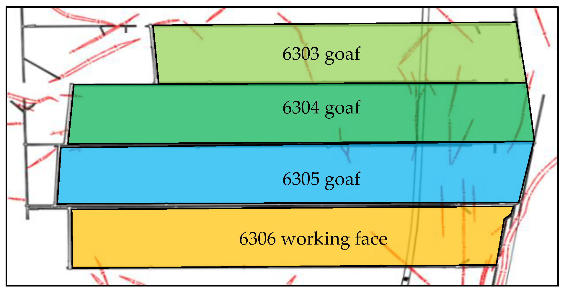
2.1. Working Face Overview of a Mine in Shandong

The 6306 fully mechanized mining face of a mine in Shandong is located in the north of the expansion area of the sixth mining area, the west side of the auxiliary transportation lane in the south wing, the 6305 goaf in the north, and the 6307 working face in the south (not developed). The roadways on both sides of the working face are parallel to each other, the roadway on the north side is the rail transportation roadway, the roadway on the south side is the transportation roadway, and the distance between the two roadways is 261.0 m, as shown in Figure 1. Working face elevation: −604.50~−670.30 m, average −637.40 m, coal seam thickness of 5.4 m. The strike length of the 6306 working face is 1456.3 m, and the inclined width is 261.0 m. Table 1 shows the stratum structure exposed by the O2-D7 borehole in the range of the 6306 working face. According to the O2-D7 borehole, the stratum is divided into three thick key stratum groups. The third key stratum group is 189 m thick and 361 m away from the coal seam. The second key stratum group is 263 m thick, 86 m away from the coal seam, and the first is 29 m thick, 16.3 m away from the coal seam.

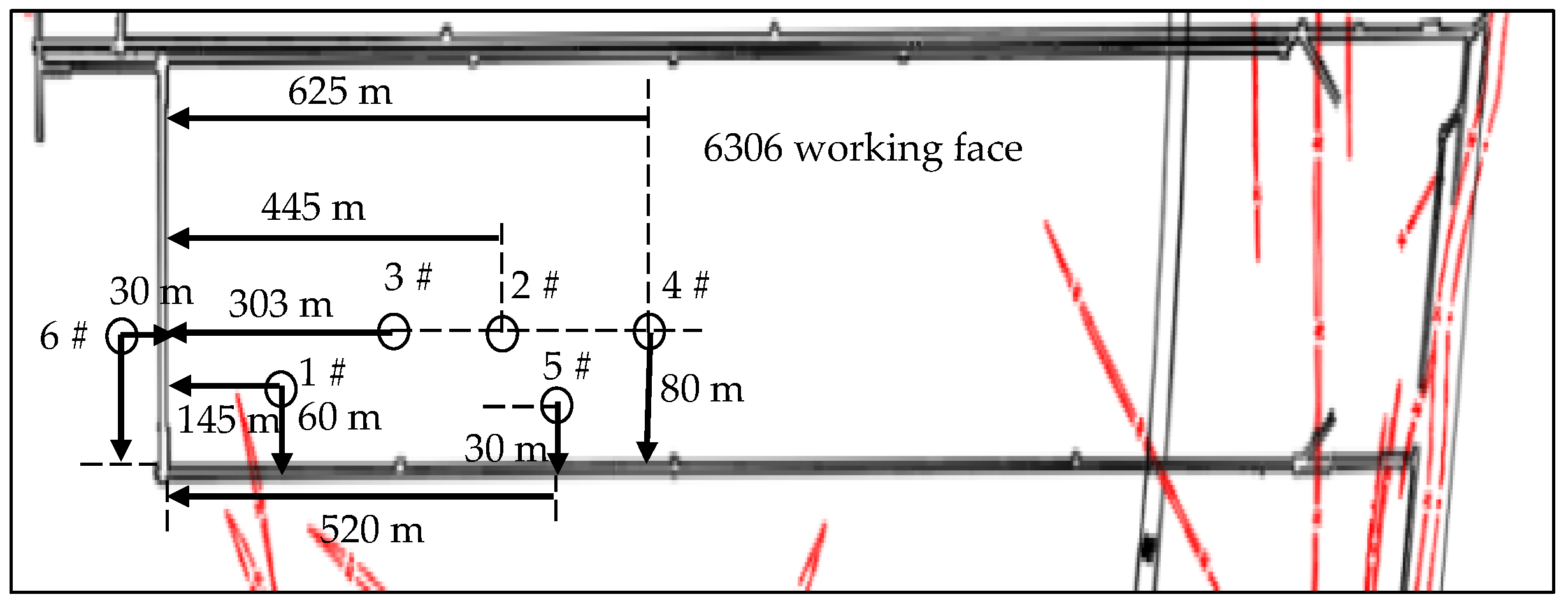
2.2. Overview of Vertical Ground Well Hydraulic Fracturing in 6306 Working Face

To control the roof movement type mine earthquake in a mine in Shandong, a method of segmented hydraulic fracturing of the thick key stratum in the vertical ground well was proposed. Six hydraulic fracturing wells were constructed in the 6306 working face. The arrangement of the ground hydraulic fracturing vertical well is shown in Figure 2. After the ground hydraulic fracturing, the third key stratum group 189 m and the second key stratum group 263 m are all pre-split in the vertical direction.

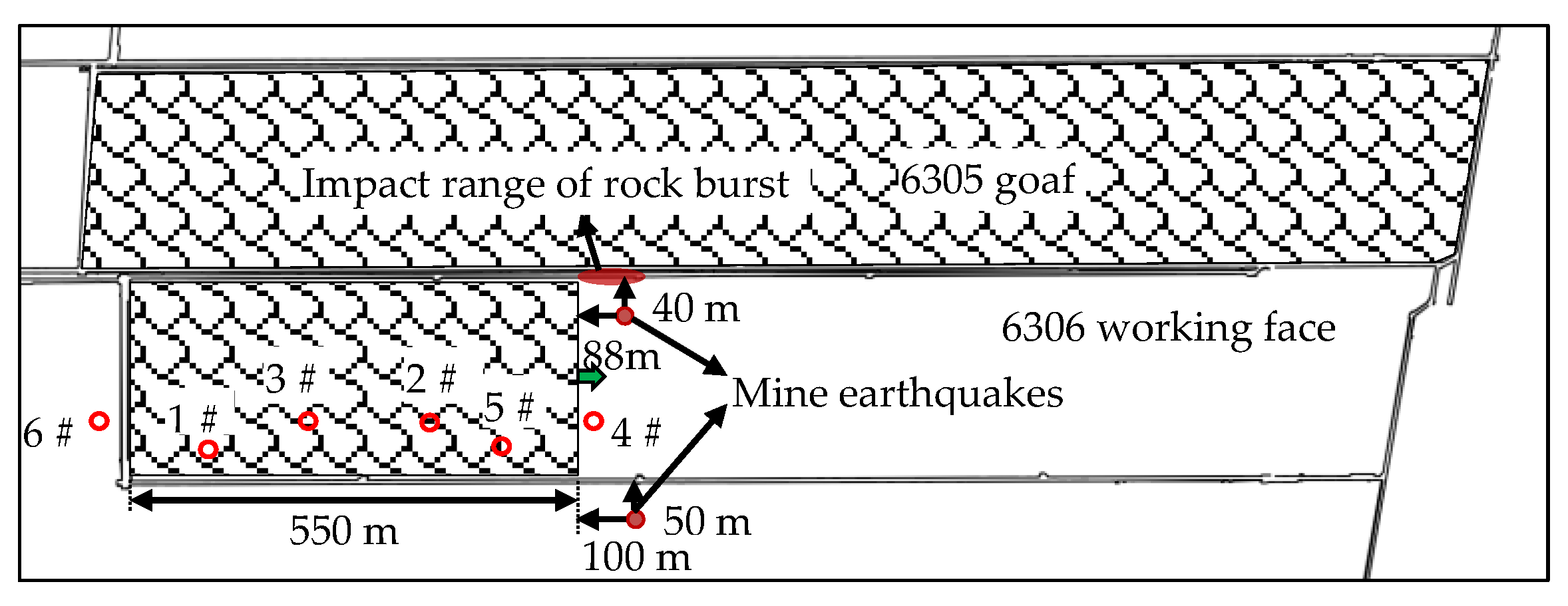
2.3. Basic Situation of ‘11.30’ Mine Earthquake in 6306 Working Face of a Mine in Shandong

On 30 November 2020, two large energy mine earthquakes of about 2.0 magnitude occurred continuously in the 6306 working face of a mine in Shandong Province within 20 s. At 9:41:29 s, the microseismic monitoring detected a vibration event with an energy of 7.55 × 10⁵ J. The source location was 88 m ahead of the 6306 working face, 40 m inside the rail transport lane, and 177 m above the coal seam roof. The magnitude was M1.9; at 9:41:49, a microseismic event with an energy of 2.38 × 10⁶ J was monitored. The source location was 100 m ahead of the 6306 working face, 50 m outside the transport roadway, and 128 m above the coal seam. The magnitude was ML2.2. The location of the two mine earthquakes is shown in Figure 3. The mine earthquake did not cause underground casualties and equipment damage, but the ground shock was obvious. Through on-the-spot investigation, it was found that the deformation of 100 m of ahead roadway and 40 m~60 m of ahead roadway of rail transport roadway in the 6306 fully mechanized mining face was serious, and there was floor heave, right side (production side) heave, and roof subsidence in some sections.
After the mine earthquake, through field investigation, the basic characteristics of the mine earthquake are as follows: (1) After the mine earthquake occurred, the underground and ground had a strong sense of earthquake; microseisms and stress were early warnings, and a wide range of movement of extremely thick hard rock led to coal stress concentration; (2) The location of the mine earthquake is in the 4 # and 5 # surface hydraulic fracturing well area; (3) The occurrence position of the mine earthquake is located in the 177 m and 128 m thick sandstone group above the coal seam, and the occurrence horizon of the first mine earthquake is higher than that of the second mine earthquake; (4) When the mine earthquake occurred, the working face advanced about 550 m, which is located near the square position of the double mined-out area (the 6305 mined-out area oblique width 270 m); (5) The time interval between the two mine earthquakes was short, only 20 s apart. After the mine earthquake, there was deformation of the 100 m roadway ahead of the gob-side entry of the 6306 working face, the local floor heaved and bulged, and some sections of the roof subsided.

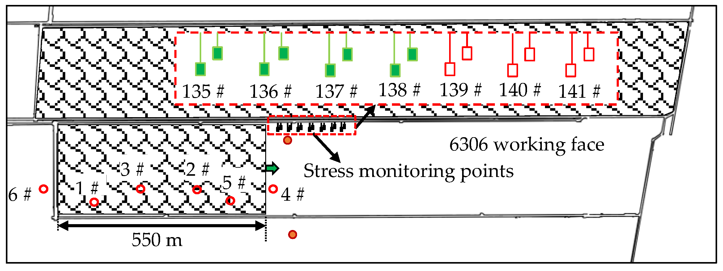
2.4. Analysis of Monitoring Data before and after ‘11.30’ Mine Earthquake

The stress monitoring points in the range of 300 m near the source position of the track transport roadway side of the 6306 working face are arranged as shown in Figure 4. Each set of stress monitoring stations contains two measuring points with hole depths of 8 m and 14 m, respectively. Each set of stress monitoring stations is 20 m apart, and the number of monitoring stations in front of the working face is 135–141, respectively. When the ‘11.30’ mine earthquake occurred, the stress values of the 135th to 138th groups of the stress monitoring stations suddenly decreased (Figure 4). Therefore, the stress values of groups 139 to 141 of the stress monitoring station increased.
The data change characteristics and early warning process of online monitoring and early warning system of stope stress are as follows:
The early warning time of the stress online monitoring system is 09:41 on 30 November 2020. The stress values of the 135th to 138th groups of the stress monitoring station on the side of the rail transportation lane all showed a sudden drop. As shown in Figure 5, the maximum reduction of stress values in shallow and deep holes in the 135th group of stations were 2.6 MPa and 4.7 MPa, respectively; the maximum reduction of shallow and deep hole stress values in the 136th group of stations were 3.1 MPa and 1.6 MPa, respectively; the maximum reduction of shallow and deep hole stress values at the 137th group of stations were 2.2 MPa and 1 MPa, respectively; the maximum reduction of shallow and deep hole stress values in the 138th group of stations were 3.4 MPa and 2.9 MPa, respectively. Finally, the stress values of the 139th group to the 141st group of the track roadway side stress monitoring station increased, are shown in Figure 5. Among them, the maximum increase of the shallow hole and deep hole stress values of the 139th group of stations were 3.3 MPa and 12.7 MPa, respectively. The maximum increase of shallow and deep hole stress values in the 140th group of stations were 0.5 MPa and 0.6 MPa, respectively; the maximum increase of stress value of shallow hole and deep hole in group 141 were 0.2 MPa and 0.5 MPa, respectively.
The microseismic events monitored by the online microseismic monitoring system before and after the ‘11.30’ mine earthquake are shown in Figure 6. It can be seen from the figure that before the mine earthquake, the total number of single-day microseismic and the total energy of single-day micro seismic increased, indicating that the movement of the overlying strata of the coal seam intensified before the mine earthquake. On the day of the mine earthquake, the total energy of single-day microseism was the largest, 3 × 10⁹ J; the number and energy of microseismic events decreased sharply after the mine earthquake, indicating that the overlying strata of the coal seam were fully moved, and the accumulated elastic energy was fully released when the mine earthquake occurred.

3. Similar Material Simulation Test Study on Dynamic Disaster of Thick Hard Roof Induced by Water Pressure Fracturing in Vertical Well

A similar material simulation test was conducted to study the dynamic disaster mechanism of an extremely thick hard roof induced by hydraulic fracturing in a vertical shaft. Similar material simulation experiments were carried out on coal seam mining in working face without vertical ground well hydraulic fracturing and coal seam mining with vertical ground well hydraulic fracturing.

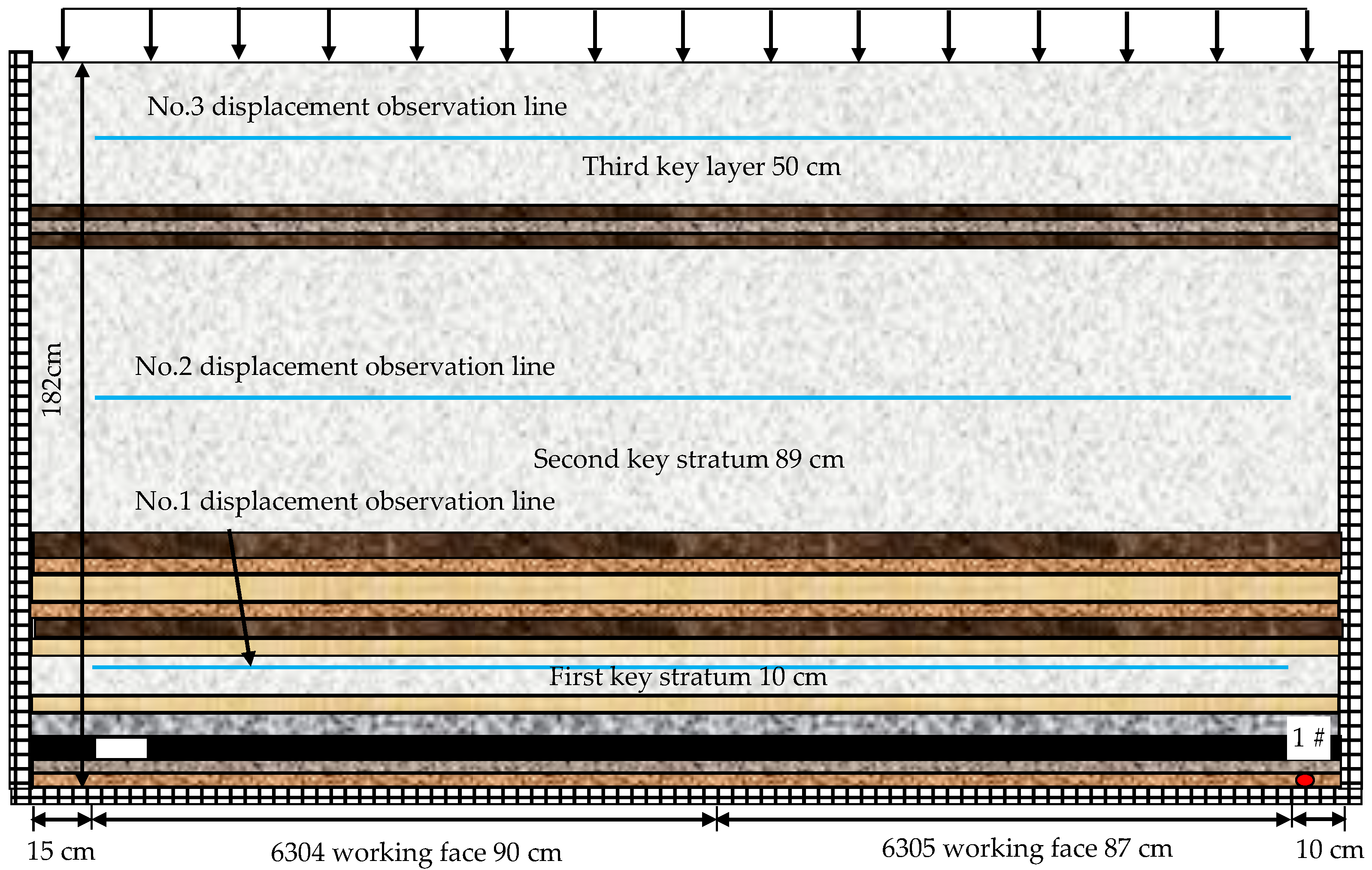
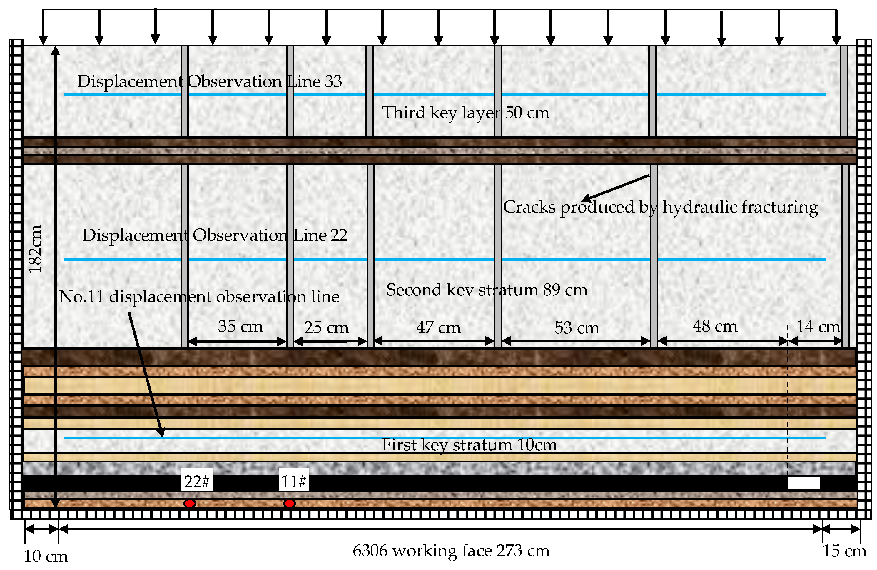
3.1. Simulation Test Scheme of Similar Material

According to the occurrence of rock strata, physical and mechanical properties of rock, and the geometric dimensions of similar simulation frame systems in the 6306 working face, the similarity ratio was determined according to three basic similarity laws. The geometric ratio was α l = 1 / 300 ; the bulk density ratio was α γ = 0 . 6 ; the strength ratio was σ m = 180   σ h ; the time ratio was α t = α l = 1 / 17 . For the convenience of time simulation, the time ratio was α t   = 1/24. Working face daily footage was 3 m, that is, a test of a 60 min excavation of 1 cm. The experiment used fine sand as aggregate, calcium carbonate and gypsum as cementing materials, and mica powder as layered material. When the thickness of the rock layer is less than 3 m (the simulated thickness is less than 1 cm), the rock layer is thickened or omitted by rounding. The final test simulated rock layer thickness and test material ratio are shown in Table 2.
Figure 7 shows the mining test design scheme of the 6304 and 6305 working faces. The size of the experimental model was L × B × H = 2020 mm × 250 mm × 1820 mm. A uniform load of 6 kN was applied to the roof of the model. Three displacement observation lines were laid in the test. The first displacement observation line is 5 cm away from the coal seam. The second displacement observation line is 62 cm away from the coal seam. The third displacement observation line is 132 cm away from the coal seam. In the test, a strain-type miniature earth pressure box was buried in the coal seam floor. The No.1 earth pressure box was 180 cm from the open-off cut, as shown in Figure 7.
Figure 8 shows the mining test design scheme of the 6306 working face after a simulated hydraulic fracturing. The size of the experimental model was L × B × H = 298 cm × 25 cm × 182 cm, and a uniform load of 6 kN was applied to the roof of the model. According to the relative position relationship of the ground hydraulic fracturing well in Figure 3, when the test model was stacked, a steel plate with a thickness of 1 mm was pre-buried in the fracturing target rock group, and the steel plate was extracted after the model was dried to form artificial cracks. Three displacement observation lines were laid in the test. The first displacement observation line is 5 cm away from the coal seam. The second displacement observation line is 62 cm away from the coal seam. The third displacement observation line is 132 cm away from the coal seam. Furthermore, two strain micro earth pressure boxes were buried in the coal seam floor. The No.11 earth pressure box was 181 cm away from the open-off cut, and the No.22 earth pressure box was 212 cm away from the open-off cut, as shown in Figure 8.

3.2. Movement Law of Overlying Strata in Coal Seam Mining before Hydraulic Fracturing of Surface Vertical Well

Figure 9 is the result of simulating the overlying strata movement of the 6304 and 6305 working faces. It can be seen from the diagram that the fracture angle of rock strata is approximately 80°. When the 6304 and 6305 working faces were mined in sequence, the immediate roof directly fell in the early mining stage, forming an irregular caving zone. With the increase in mining distance, there was bending deformation of low-key strata; as the mining distance continued to increase, the rock beam bent and sank, and the upper key stratum periodically began to separate and bend, layer by layer. However, a stable rock beam structure could be formed due to the large thickness and high strength of the second key stratum.

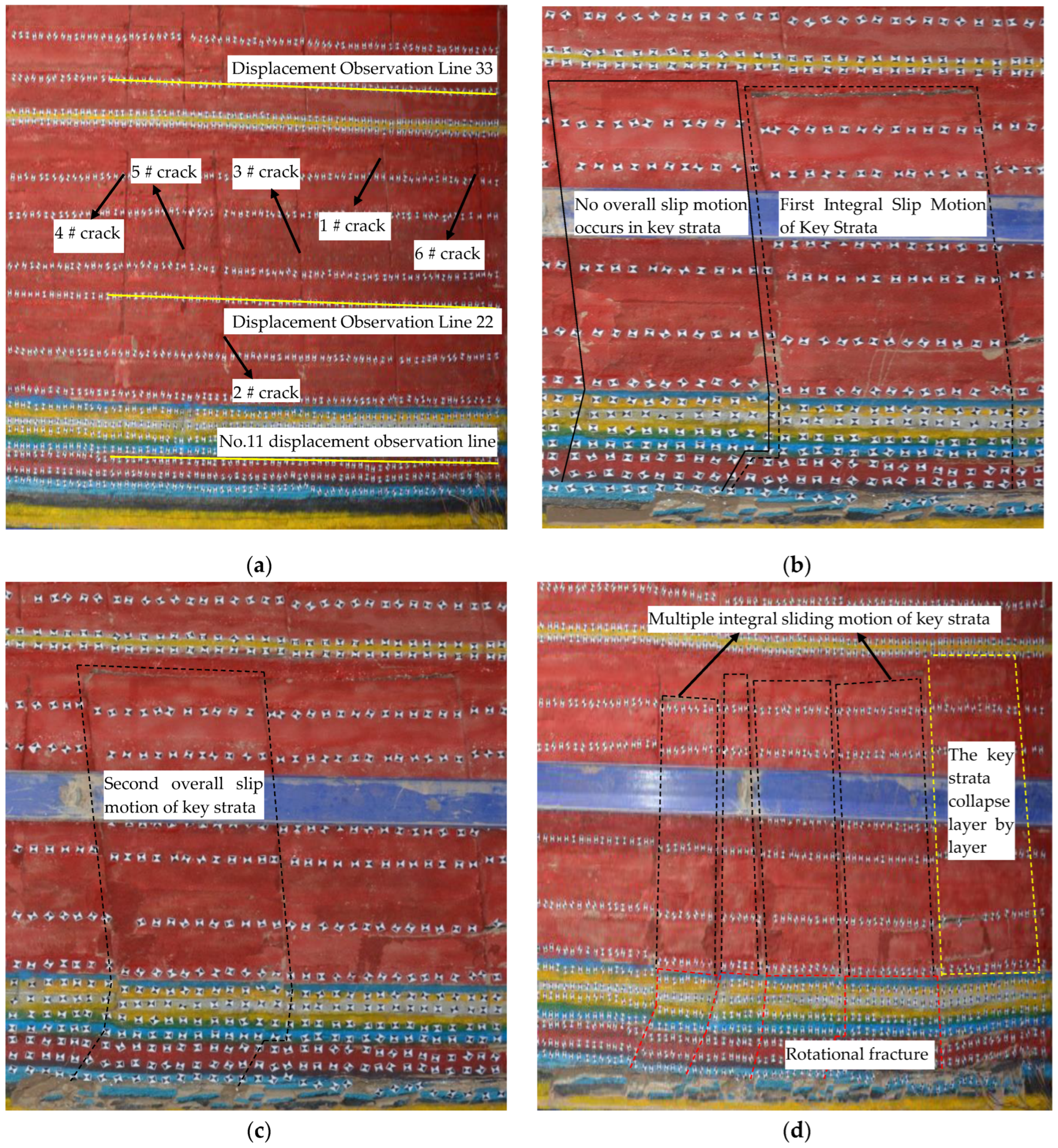
3.3. Movement Law of Overlying Strata after Hydraulic Fracturing of Vertical Ground Well

Figure 10 shows the simulation results of the overlying strata movement of the 6306 working face after hydraulic fracturing. It can be seen from the figure that the fracture angle of rock strata was approximately 82°. After the ground hydraulic fracturing was adopted in the 6306 working face, the thick and hard key strata formed vertical cracks near the fracturing well. When the coal was recovered from the open-off cut 0–145 m (#6 fracturing crack was located on the right side of the open-off cut 30 m, #1 fracturing crack was located on the left side of the open-off cut 145 m), including an increase in mining distance, the low key stratum was affected by the compression of the high key stratum, and gradually bent and sank in the direction of the #1 fracturing crack. At this stage, the key stratum gradually began to leave the layer and formed a stable cantilever beam structure. When the mining distance exceeded 145 m, the overlying high-level key strata in the goaf would not undergo layer-by-layer separation and bending deformation. Still, they would undergo overall slip motion, which would simultaneously suppress the rotation instability of the lower key strata. Subsequently, the overburden load would be transmitted to the coal body in front of the working face, which could easily induce the overall slip motion type mine earthquake and rock burst.
Figure 10b is a photograph of the test to 174 cm (the actual mining 522 m). Currently, the key layer did not occur during the second overall slip movement; Figure 10c is a photo of the test mining to 177 cm (the actual mining is 531 m). At this time, the second overall sliding motion occurred in the key stratum, close to the mining distance (550 m) when the ‘11.30’ mine earthquake occurred. Therefore, the ‘11.30’ mine earthquake in the 6306 working face is a dynamic disaster due to the whole sliding movement of the highly thick hard roof induced by the hydraulic fracturing of the vertical shaft.
Comparing the simulation results of two similar materials, it can be observed that the fracture angle of the rock layer increased after the hydraulic fracturing of the thick and hard roof of the vertical ground well. After the hydraulic fracturing of the super-thick hard roof in the vertical ground well, the movement mode of the super-thick hard rock above the coal seam changed from periodic layer-by-layer movement to overall sliding movement.

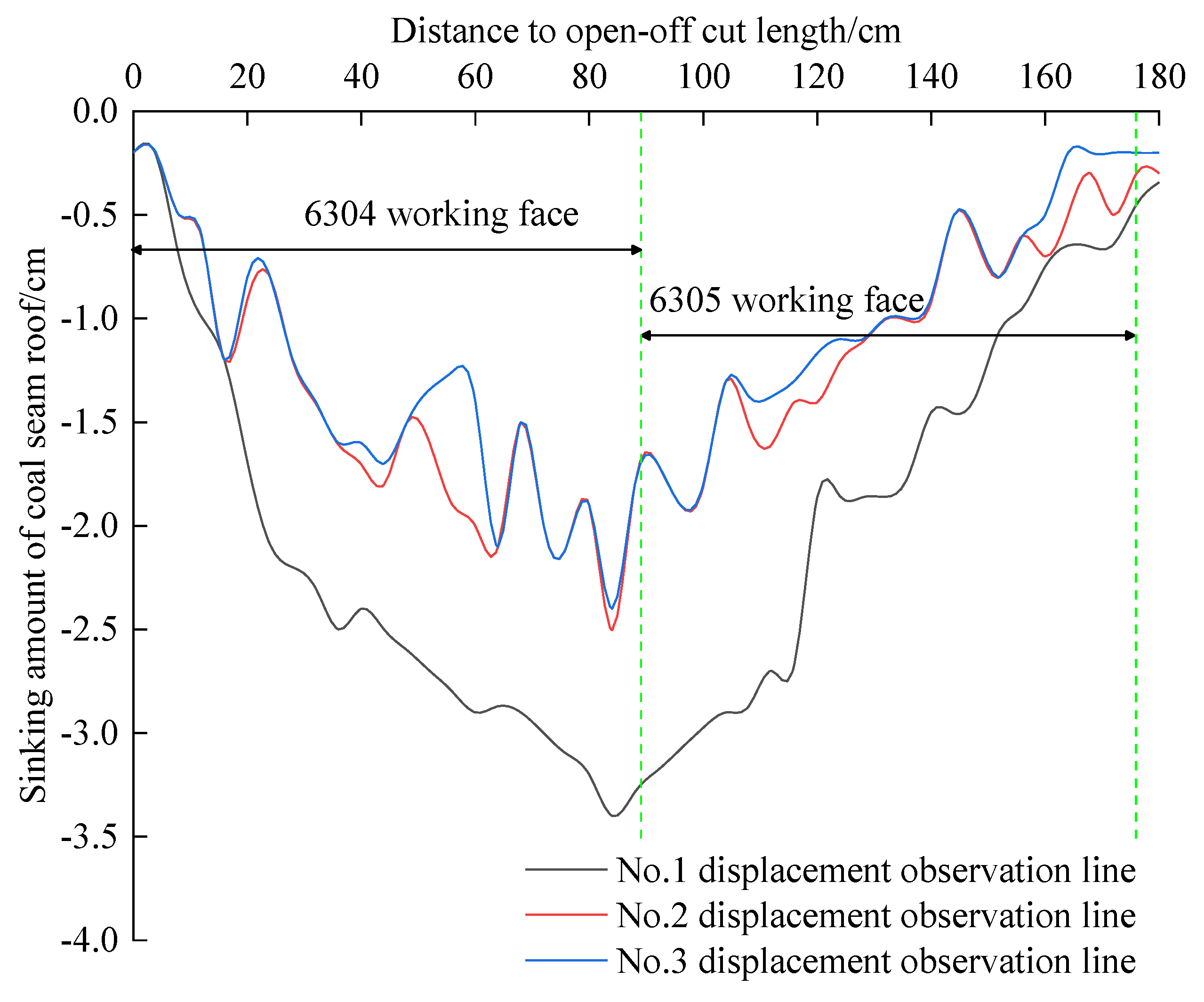
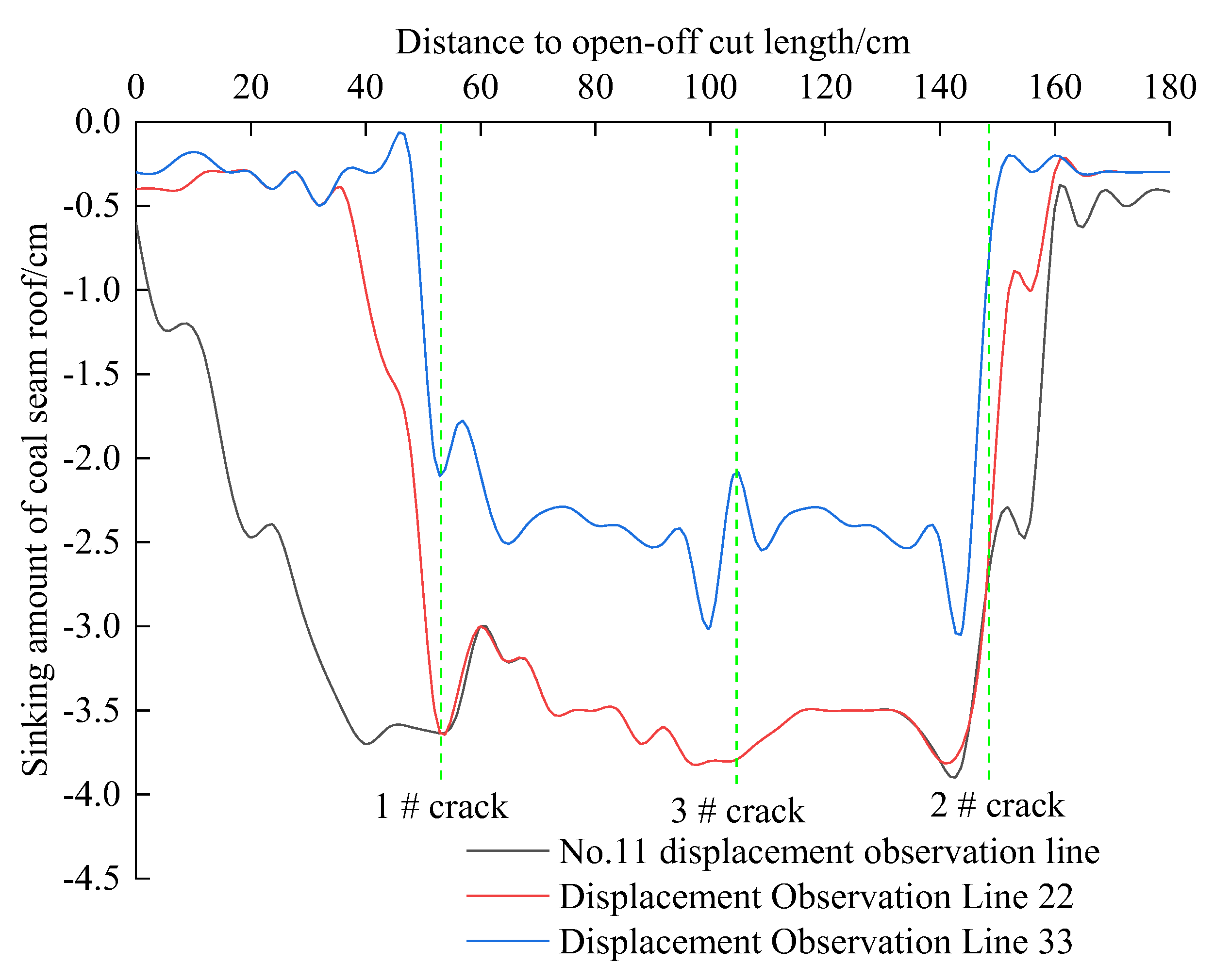
3.4. Vertical Displacement Monitoring Results of Similar Material Simulation Test

According to the observation data of the displacement observation line during the test, the vertical displacement curves of the three groups of key strata above the coal seam of 177 cm (531 m) were obtained, as shown in Figure 11 and Figure 12.
As can be seen from Figure 11, when the vertical surface well hydraulic fracturing measures were not taken, and the mining was pushed to 177 cm (actual mining 531 m), the three key strata had the largest subsidence at 84 cm from the open-off cut. Additionally, the subsidence curve of the three displacement observation lines demonstrated ‘basin-bottom’ distribution, where the first key strata group sank 3.4 cm, the second key strata group sank 2.5 cm, and the third key strata group sank 2.4 cm.
Figure 12 shows that when the working face was pushed to 177 cm (the actual mining is 531 m) after the vertical ground well hydraulic fracturing measures were taken, the maximum subsidence of the three key strata groups was within the fracturing range. Notably, the roof subsidence curves of the No.11 and No.22 displacement observation lines between No.1 and No.2 fracturing cracks coincided. The roof subsidence curve of the No.33 displacement observation line between the No.1 and No.2 fracturing cracks was consistent with the changing trend of No.11 and No.22 displacement observation lines, showing that the rock mass between fracturing cracks during coal seam mining occurs as an overall slip movement, rather than layer-by-layer movement. Furthermore, the subsidence curve of the three displacement observation lines showed a ’flat-bottom’ distribution. Among them, the maximum subsidence of the first and second key strata was 3.8 cm, and the maximum subsidence of the third key strata was 2.5 cm.
From Figure 11 and Figure 12, we can see that the roof subsidence curves of the two working conditions are entirely different. After the hydraulic fracturing of the ground vertical well’s extremely thick and hard roof, the movement mode of the extremely thick and hard rock layer above the coal seam was changed. Additionally, the movement mode of the extremely thick and hard rock layer was changed from layer-by-layer movement to overall slip movement.

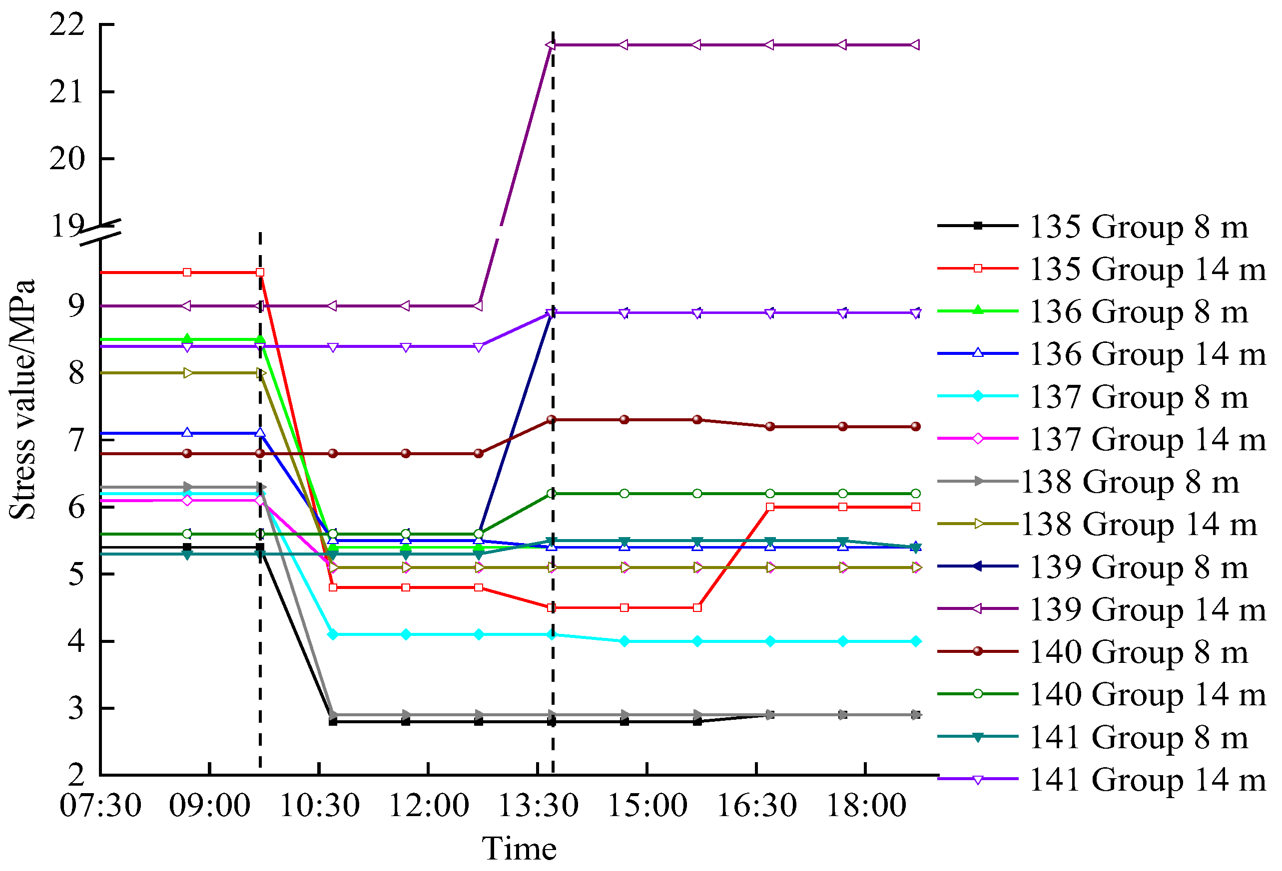
3.5. Stress Monitoring Results of Similar Material Simulation Test

According to the monitoring data of the coal seam floor stress sensor during the test, the vertical stress change curve in the process of mining 174 cm~177 cm (actual mining 522 m~531 m) was obtained, as shown in Figure 13.
It can be observed from Figure 13 that in the process of mining 174 cm to 177 cm in the working face without vertical ground well hydraulic fracturing measures, the vertical stress of the No.1 measuring point increased slowly, and the No.1 measuring point rose from the initial 18 kPa to 30.85 kPa. In this process, the vertical stress of the No.1 measuring point increased by 12.85 kPa.
From Figure 13, the vertical stress of the No.11 measuring point and No.22 measuring point increased slowly during mining 0–181 min (174 cm~177 cm) after taking the hydraulic fracturing measures of the vertical ground well. The vertical stress of the No.11 measuring point increased from the initial 20 kPa to 27.8 kPa, and the vertical stress of the No.11 measuring point increased by 7.8 kPa in this process. Additionally, the vertical stress of the No.22 measuring point increased by 6.3 kPa from the initial 15 kPa to 21.3 kPa. However, at 182 min, the vertical stress of the No.11 measuring point and No.22 measuring point changed abruptly, and the vertical stress of the No.11 measuring point increased from 27.8 kPa to 45 kPa. Furthermore, the vertical stress value of measuring point 22 decreased from 21.3 kPa to 20.3 kPa. According to the previous analysis, when the working face was pushed to 177cm, the overlying key layer of the coal seam was affected by the No.3 hydraulic fracturing fracture and the No.2 hydraulic fracturing fracture, and the key layer slips, resulting in the instantaneous increase of the abutment pressure of the working face. Therefore, it was easy to induce large energy mine earthquakes and rock bursts. The No.22 measuring point was 31 cm away from the coal wall (equivalent to 93 m from the coal wall). At this moment, the No.22 measuring point is in the range of the pressure relief zone, suggesting that the advanced influence range of coal seam mining after hydraulic fracturing is about 100 m.

4. Study on Dynamic Disaster Mechanism of Thick Hard Roof Induced by Water Pressure Fracturing in Vertical Well

In the extremely thick and hard roof mine, before the hydraulic fracturing of the vertical ground well was carried out, part of the roof strata collapsed during the mining process of the working face, resulting in the bending, and sinking, or even breaking, of the overlying strata in the caving zone. During the movement of the overlying strata, the load is transferred to the coal on both sides of the working face to form the advanced abutment pressure. Therefore, there is an inevitable relationship between the advanced abutment pressure and the movement law of the overlying strata.
When the ‘11.30’ mine earthquake occurred, the 6306 working face advanced to the square position of the double working face. According to the key stratum theory, the key stratum load includes the weight of the key stratum and the weight of the rock stratum group controlled by it. After the working face is mined, the load borne by the hanging part of the key strata is transferred to the coal body on both sides of the goaf by taking the rock mass on both sides of the goaf as the supporting points. Subsequently, the load transferred to the side of the goaf is half of the weight of the hanging part of the key strata and the weight of the strata group controlled by it.

4.1. Estimation of Advanced Abutment Pressure in Coal Seam Mining before Hydraulic Fracturing of Vertical Surface Well

According to the theory of key strata and the load transfer characteristics of overlying strata, the calculation model of strike abutment pressure when the key strata are broken is established. As shown in Figure 14, the rectangular coordinate system is installed with the coal wall as the origin and the advancing direction of the working face as the x-axis. During the excavation of the coal seam, the fracture of the roof strata of the coal seam moved in the unit of the strata group, and the key strata in the strata group controlled the overall movement of the strata group. After the coal seam was mined, the constant load state of the roof strata was destroyed, causing the load to transfer to the front of the goaf and the coal wall.
From Figure 14, it can be seen that the strike abutment pressure σ on the coal body on one side of the goaf is formed by the superposition of the stress increment sum σ n and the self-weight stress σ q transferred by the overlying strata of the goaf, as shown in the following Formulas (1) and (2):
σ = σ n + σ q
σ n = i = 1 n σ i
Because the thin, weak interlayer in the upper part of key layer i moves synchronously with key layer i. To facilitate the calculation, the self-weight stress of the weak interlayer is regarded as applying a uniform load above the key layer i. The stress increment transmitted from the hanging or hinged failure of the key layer to the strike coal body is approximately in an isosceles triangle distribution, as shown in Figure 14. Then σ i can be represented by Equation (3).
σ i = { x σ m a x i tan α H i [ 0 , H i tan α ] 2 σ m a x i [ 1 x tan α 2 H i ] [ H i tan α , 2 H i tan α ]         0 [ 2 H i tan α , + ]  
where σ m a x i is the maximum supporting stress produced by the key stratum on the coal seam, MPa.
σ m a x i = ( L w i tan α H i + 1 ) γ h i 2 + γ h i L w i tan α 2 H i - h i  
In the formula, H i is the distance from the center line of the key layer i to the coal seam; h i is the thickness of key layer i; L w i is the length of i key stratum exposed on the goaf; h i is the thickness of the weak intercalated layer controlled by key stratum i; γ is rock bulk density, 0.025 MN/m3; α is the fracture angle of the rock.
The expression of gravity stress is according to Formula (5).
σ q = { x γ tan α           [ 0 , H tan α ] γ H                                 [ H tan α , + ]  
H is the depth of the coal seam.
According to the O2-D7 drilling formation parameters in Table 1, the overlying strata of the 6306 working face is divided into three key strata, namely n = 3; H 1 = 30.8 m, H 2 = 218.05 m, H 3 = 455.35 m, h 1 = 29 m, h 2 = 263.4 m, h 3 = 189.2 m, h 1 = 41.05 m. h 2 = 11 m, h 3 = 125.9 m; when the ‘11.30’ mine earthquake occurred, the mining distance L = 550 m, the average mining depth H = 700 m, and the uniaxial compressive strength of coal was 21 MPa; according to the simulation results of similar materials, α = 80°, according to the mining experience of the mining area where the mine seismic working face is located, the average step distance of the main roof periodic weighting is 24 m, then L w 1 = 48 m; critical to the key stratum theory, the limit caving degree of the second key stratum is 217 m, and the limit caving step of the third key stratum is 234 m. When the mine earthquake occurs, the working face advances to 550 m, so L w 2 = L     217   ×   2 = 116   m ; L w 3 = L     234   ×   2 = 82   m .
The above parameters are substituted into Formulas (1) to (5), respectively, and the theoretical calculation curve of abutment pressure before hydraulic fracturing of the 6306 working face is shown in Figure 15.
It can be seen from Figure 15 that before the hydraulic fracturing of the super-thick hard roof in the vertical ground well, the advance influence range of coal seam mining was 160.62 m, the peak value of the advanced abutment pressure was 22.69 MPa, and the peak value is 38.46 m from the coal wall. In this case, the peak value of advanced abutment pressure is less than 1.5 times the uniaxial compressive strength of the coal seam, which does not reach the critical value of a coal seam burst.

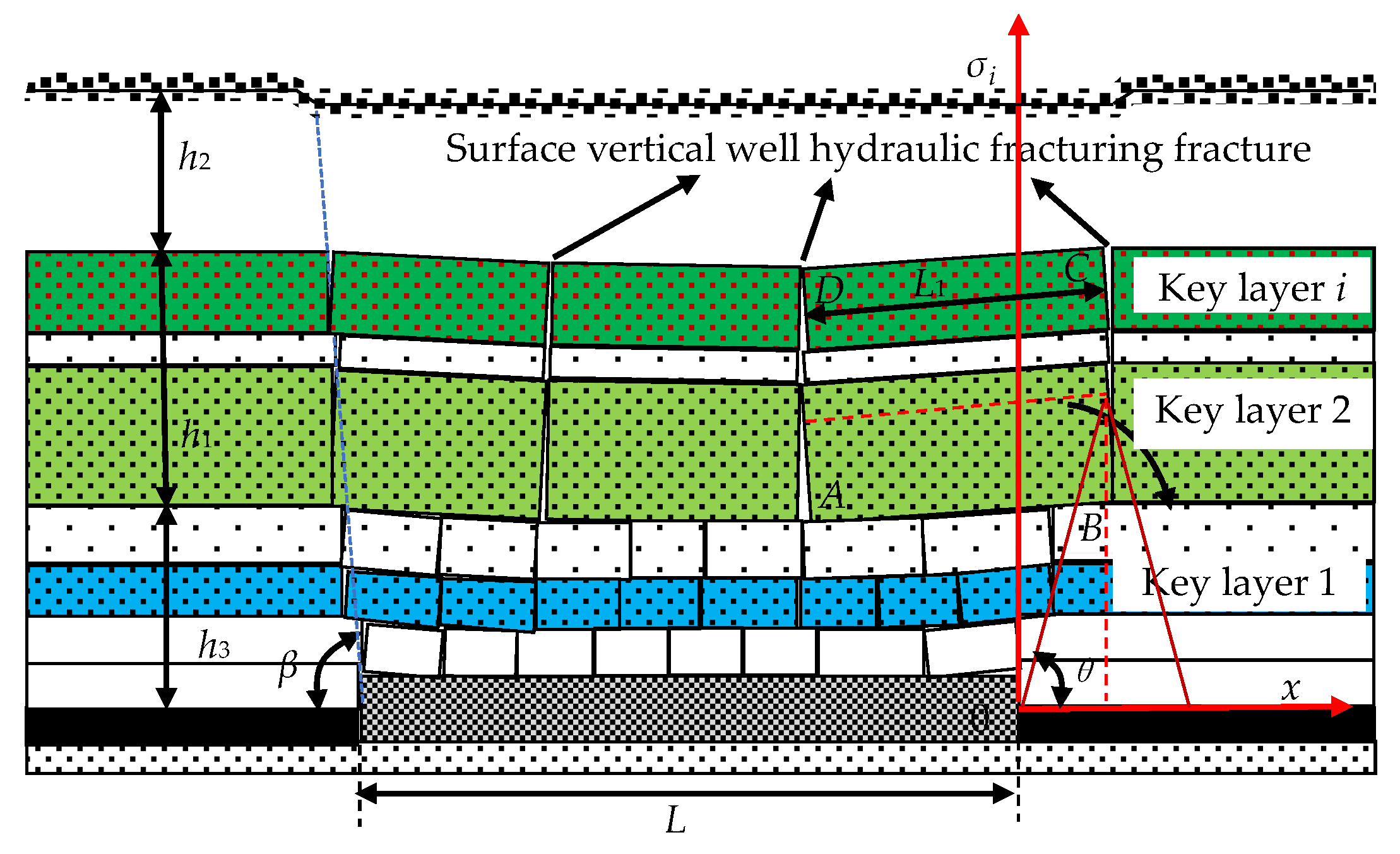
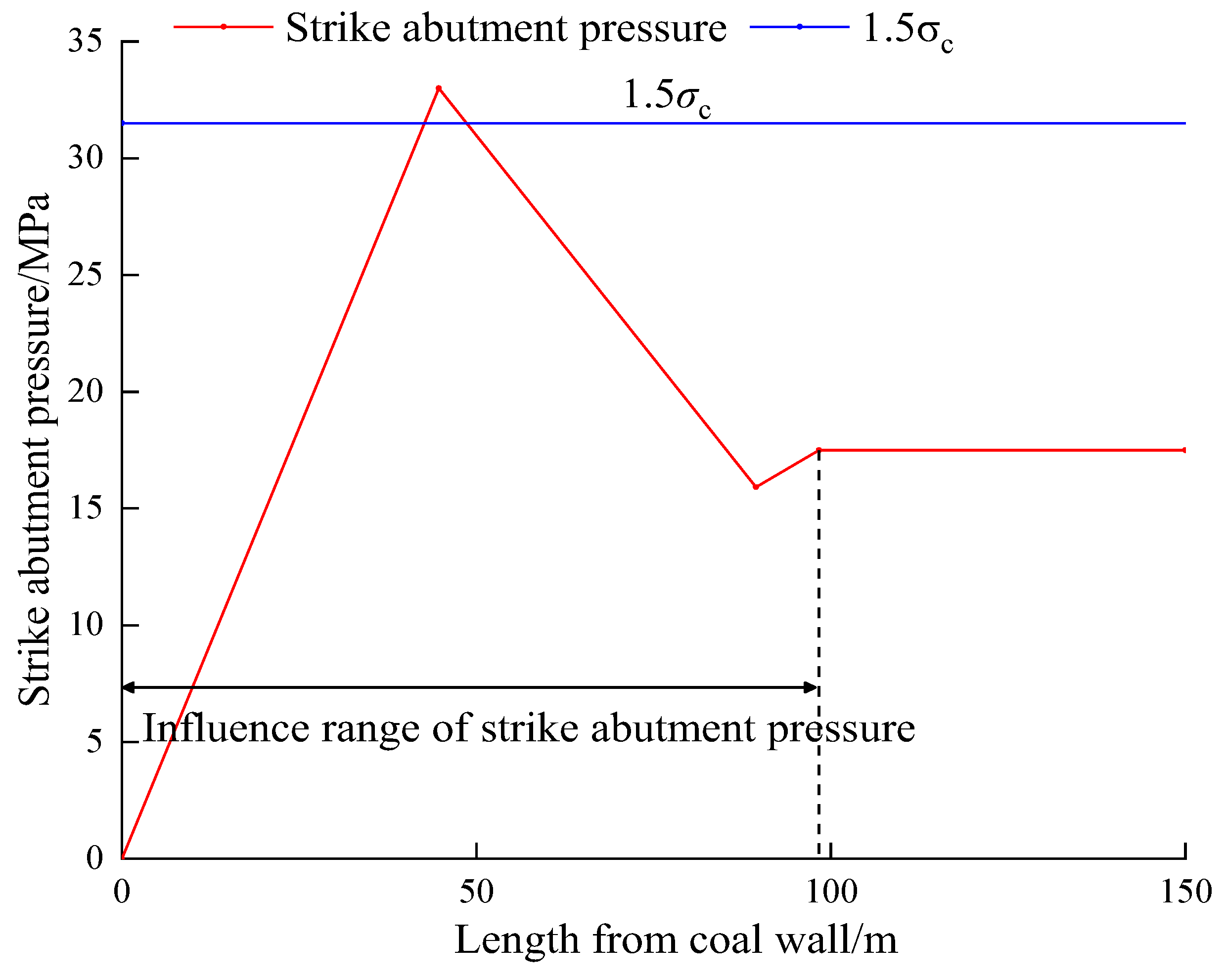
4.2. Estimation of Advanced Abutment Pressure in Coal Seam Mining after Hydraulic Fracturing of Super Thick Hard Roof in Vertical Well

According to the spatial structure of the overlying strata after the hydraulic fracturing of the vertical ground well in the double square stage of the 6306 working face, the calculation model of the strike abutment pressure is established. As shown in Figure 16, the rectangular coordinate system is installed with the coal wall as the origin and the advancing direction of the working face as the x-axis. During the excavation of the coal seam, the roof of the coal seam moves as a unit of the rock mass between the two fracturing wells. Furthermore, according to the simulation results of similar materials, after the hydraulic fracturing of the vertical ground well, the key layer slips, and the overall slip motion compresses the rotation instability of the lower key layer. Doing so transfers the overburden load to the coal body in front of the working face. In this process, a mine earthquake or rock burst occurs. According to the simulation results of similar materials, the movement of extremely thick hard rock is affected by vertical fractures after the hydraulic fracturing of extremely thick hard rock in vertical wells. The rock strata clamped by vertical cracks slip integrally under the action of self-weight stress. At this time, the advance support stress of the coal seam is composed of the self-weight stress transferred from the rock strata clamped by vertical cracks and the self-weight of the rock strata above the coal seam.
It can be seen from Figure 16 that after the hydraulic fracturing of the vertical ground well, the strike abutment pressure of the working face is formed by the superposition of the self-weight of the block ’ABCD’ and the self-weight transfer stress σ m of the overlying strata controlled by it and the self-weight stress σ p above the coal seam, as shown in Equations (6) and (7).
σ = σ m + σ p  
σ m = j = 1 m σ j  
The stress increment transferred from the self-weight of block ‘ABCD’ to the strike coal body is approximately in an isosceles triangle distribution. For the convenience of calculation, the block ‘ABCD’ is considered a rectangle. According to the simulation results of similar materials, the block ‘ABCD’ moves synchronously as a whole, then σ j can be expressed by Equation (8).
σ j = { x σ m a x j tan θ h 3 [ 0 , h 3 tan θ ] 2 σ m a x j [ 1 - xtan θ 2 h 3 ] [ h 3 tan θ , 2 h 3 tan θ ] 0   [ 2 h 3 tan θ , + ]  
In the formula, σ m a x j is the maximum bearing stress of the block ‘ABCD’ on the coal seam, MPa.
σ m a x j = ( L 1 tan θ h 3 + 1 ) γ h 1 2 + γ h 2 L 1 tan θ 2 h 3 h 1  
In the formula, L w is the length of the block formed by fracturing cracks exposed on the goaf; h 1 is the distance from the second key stratum to the n key stratum above the coal seam; h 2 is the distance from the n key stratum above the coal seam to the surface; h 3 is the distance from block ‘ABCD’ to the coal seam; θ is the rock fracture angle after hydraulic fracturing.
The expression of gravity stress σ p is as shown in Formula (10).
σ p = { x γ tan θ [ 0 , H tan θ ] γ H [ H tan θ , + ]
In the formula, γ is the rock bulk density, 0.025 MN/m3; H is the depth of the coal seam.
When the ‘11.30’ mine earthquake occurred, the mining distance L = 550 m, the average mining depth H = 700 m, and the uniaxial compressive strength of coal was 21 MPa. According to the similar material simulation results θ = 82°, according to the O2-D7 drilling formation parameters in Table 1, h 1 = 463.6 m, h 2 = 125.9 m, h 3 = 86 m can be determined. The location of the ‘11.30’ mine earthquake is between #4 and #5 surface hydraulic fracturing vertical wells. According to the arrangement of fracturing wells, it can be determined that L 1 is 105 m. Substituting the above parameters into Equations (6)–(10), the theoretical calculation curve of advanced abutment pressure after hydraulic fracturing of super thick hard rock strata in the vertical ground shaft of the 6306 working face is shown in Figure 17.
According to Figure 17, after the hydraulic fracturing of the super-thick hard rock formation group in the vertical ground well, the advanced influence range of coal seam mining is 98.31 m, which is consistent with the simulation results of similar materials and the deformation range of the ‘11.30’ roadway. The peak value of the advanced abutment pressure is 33 MPa, and the peak value is 44.71 m from the coal wall, equivalent to the ‘11.30’ impact range (the roadway deformation is a serious advance of 40 m–60 m). The peak value of the advanced abutment pressure is greater than 1.5 times the uniaxial compressive strength of the coal seam, reaching the critical value of the coal seam impact.

4.3. Study on Dynamic Disaster Mechanism of Thick Hard Roof Induced by Hydraulic Fracturing in Vertical Well

According to the theoretical calculation results of the advanced abutment pressure before and after the hydraulic fracturing of the vertical surface well (Figure 18), after the hydraulic fracturing of the extremely thick and hard key layer in the vertical surface well, the influence range of the advanced abutment pressure during the coal seam mining process (98.31 m) is 38.79% lower than before the fracturing (160.62 m). Additionally, the peak abutment pressure (33 MPa) increased by 45.44% compared with that before fracturing (22.69 MPa). Furthermore, the distance between the peak abutment pressure and the coal wall (44.71 m) increased by 16.25% compared with before fracturing (38.46 m).
After the hydraulic fracturing of the extremely thick and hard roof in the vertical surface well, during the coal seam mining, the motion mode of the extremely thick and hard rock strata overlying the coal seam changes from layer-by-layer motion to overall slip motion. The overburden load is then transmitted to the coal body in front of the working face, resulting in the peak value of the advanced abutment pressure (compared with normal mining). Due to hydraulic fracturing cracks in the overlying hard rock strata before and after coal seam mining, the overlying hard rock strata have an overall sliding motion at the hydraulic fracturing cracks, thereby increasing the fracture angle of the overlying hard rock strata. The peak point of the abutment pressure (compared with normal mining) moves to the rear of the coal wall, and the influence range of the abutment pressure (compared with normal mining) decreases. Therefore, it is easy to cause a large energy mine earthquake or rock burst in the working face and its two sides if the peak value of the advanced abutment pressure of the coal seam after hydraulic fracturing of the vertical ground well exceeds 1.5 times the uniaxial compressive strength of the coal seam.

5. Technical Optimization Scheme of Ground Hydraulic Fracturing Thick Hard Roof

According to the above analysis, the mechanism of the dynamic disaster of the extremely thick and hard roof induced by the hydraulic fracturing of the vertical wells is that the hydraulic fracturing of vertical wells creates the conditions for the overall sliding movement of the extremely thick and hard roof, changes the movement mode of the extremely thick, and affects the general sliding movement of the extremely thick and hard roof, resulting in the occurrence of underground dynamic disasters. The fundamental reason for the thick and hard roof change in movement mode is that after the hydraulic fracturing of the vertical ground wells, longitudinal cracks are formed between the overlying hard rock group. Notably, the longitudinal cracks separate the overlying hard rock group of the coal seam into ‘relatively discrete cubic rock blocks’. With the excavation of the coal seam, the basic roof gradually collapses, and the ‘relatively independent cubic rock blocks’ and the overlying strata under their control lose the support of the lower coal body and the primary roof, leading to the overall slip movement of the ‘relatively independent cubic rock blocks’. Therefore, to prevent and control the occurrence of such dynamic disasters, it should be in the ground hydraulic fracturing thick hard roof to avoid the formation of ‘relatively independent cube rock’.

5.1. Optimization Scheme of Hydraulic Fracturing Technology for Thick Hard Roof in Vertical Surface Well

From the engineering practice and similar material simulation test results and theoretical calculation results, it is found that the conventional vertical surface wells and hydraulic fracturing technology can quickly induce the overall sliding dynamic disaster of hard roofs. To realize the purpose of vertical ground well hydraulic fracturing for the prevention and control of mine earthquakes caused by the movement of extremely thick hard roofs and to effectively prevent the occurrence of mine earthquakes caused by an overall sliding movement of hard roofs, a hydraulic fracturing technology with a cross arrangement of vertical deep and shallow wells on the ground is proposed.
The conventional surface vertical well hydraulic fracturing technology is utilized to pre-split all the super-thick hard rock strata on the coal seam in the vertical direction. Additionally, the hydraulic fracturing technology of the vertical deep and shallow wells on the ground is based on the thickness and buried depth of the super-thick hard rock strata on the coal seam. Therefore, the vertical fracturing range is controlled by controlling the depth of the surface hydraulic fracturing vertical well to realize the purpose of the hydraulic fracturing super-thick hard rock strata group of the vertical deep and shallow wells on the ground, as shown in Figure 19.

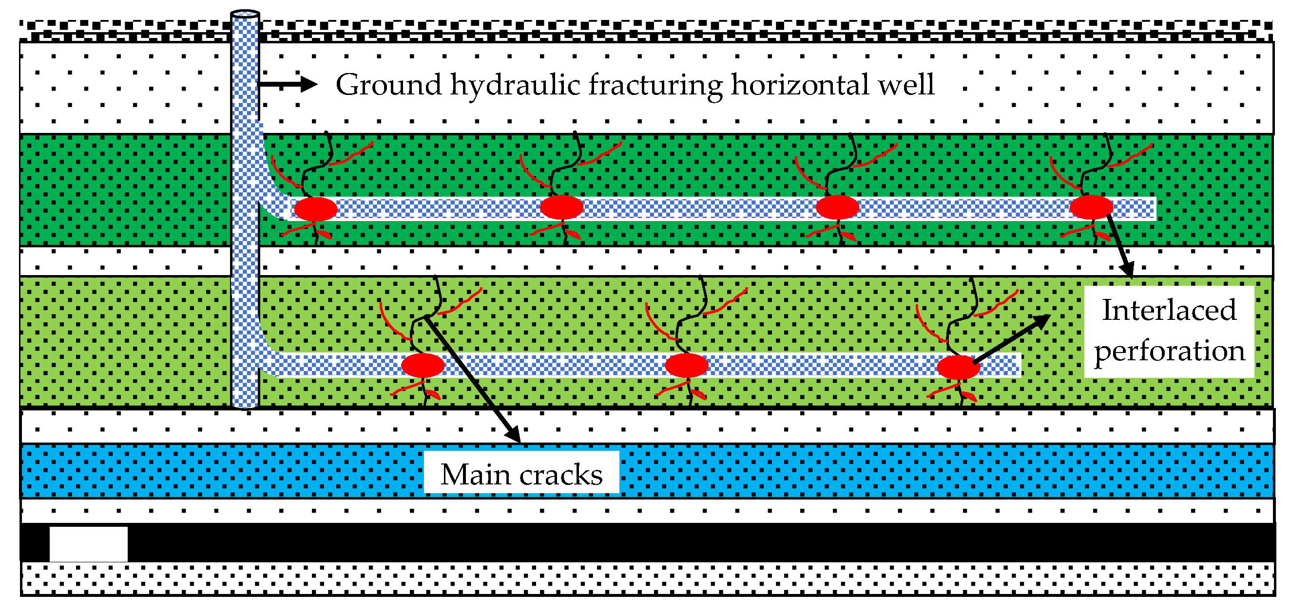
5.2. Optimization Scheme of Hydraulic Fracturing Technology for Thick Hard Roof in Surface Horizontal Well

The use of conventional surface horizontal well hydraulic fracturing technology to prevent and control the thick and hard roof movement type mine earthquakes will also separate the overlying hard rock strata of the coal seam into ’relatively independent cube rock’, thus inducing the hard roof’s overall sliding movement type dynamic disaster. Therefore, a surface multi-branch horizontal well-staggered perforation hydraulic fracturing technology is proposed, as shown in Figure 20.
Cross-perforation, hydraulic fracturing technology for multi-branch horizontal wells on the ground, is used to optimize the uniform perforation of multi-branch horizontal sections in the conventional surface horizontal well hydraulic fracturing technology into multi-branch horizontal section interval cross-perforation. By controlling the perforation position of each horizontal well branch, the formation of ’relatively independent cubic rock blocks’ can be prevented to avoid dynamic disasters caused by the overall sliding movement of extremely thick and hard roofs.

6. Conclusions

Based on the analysis of the mechanism of the ‘11.30’ mine earthquake in a mine in Shandong Province, focusing on the dynamic disaster of the thick and hard roof induced by the fracturing of the vertical ground well, we conducted a field investigation, accident case analysis, similar material simulation test, theoretical calculation, and other examinations. From these analyses, we aimed to study the motion mode of the key layer after hydraulic fracturing of the vertical ground wells and investigate the mechanism of the dynamic underground disaster. The main conclusions from these investigations are as follows:
(1) According to the simulation results of similar materials, the movement mode of the extremely thick hard rock above the coal seam is changed from layer-by-layer movement to whole sliding movement due to the hydraulic fracturing of the extremely thick hard roof in the vertical shaft;
(2) According to the theoretical calculation model of advanced abutment pressure before and after vertical surface well hydraulic fracturing, it was calculated that the influence range of advanced abutment pressure (98.31 m) after vertical surface well hydraulic fracturing was 38.79%, smaller than that before fracturing (160.62 m). Additionally, the peak abutment pressure (33 MPa) increased by 45.44% compared to that before fracturing (22.69 MPa). Furthermore, the distance between the peak abutment pressure and the coal wall (44.71 m) increased by 16.25% compared with that before fracturing (38.46 m). Therefore, a rock burst may be induced when the peak stress exceeds 1.5 times the uniaxial compressive strength of the coal seam;
(3) According to the mechanism of a mine earthquake induced by ground hydraulic fracturing, two optimization schemes of ground hydraulic fracturing technology for extremely thick and hard roofs are proposed. These proposals include cross-arranged hydraulic fracturing of vertical deep and shallow wells on the ground and staggered perforation hydraulic fracturing of multi-branch horizontal wells on the ground, forcing the extremely thick and hard rock to move in layers, leading to avoiding dynamic disasters of extremely thick and hard roofs.

Author Contributions

Conceptualization, S.Z. and F.J.; methodology, X.S. and F.J.; software, J.L. (Jiajie Li) and J.L. (Jinhai Liu); validation, X.S.; formal analysis, X.S.; investigation, X.S. and F.J.; data curation, X.S. and F.J.; writing—original draft preparation, X.S.; writing—review and editing, X.S., S.Z., F.J., J.L. (Jiajie Li), J.L. (Jinhai Liu), H.L., S.T., C.Z. and M.H.; visualization, X.S., J.L. (Jiajie Li), and M.H.; supervision, S.Z. and F.J.; project administration, F.J. and S.Z.; funding acquisition, J.L. (Jiajie Li) and S.Z. All authors have read and agreed to the published version of the manuscript.

Funding

This study was funded by the State Key Research Development Program of China, grant number 2022YFC3004604; the National Natural Science Foundation of China, grant numbers 51904017 and 52004021; the Major Science and Technology Innovation Project of Shandong Province, grant number No.2019SDZY02; the Young Talents Lifting Project of China Association for Science and Technology, grant number 2021QNRC001; Fundamental Research Funds for the Central Universities and the Youth Teacher International Exchange & Growth Program, grant number QNXM20220003; and 111 Project, grant number B20041.

Data Availability Statement

The data used to support the findings of this study are available from the corresponding author upon request.

Acknowledgments

Thanks for the journal editors and reviewers.

Conflicts of Interest

The authors declare no conflict of interest.

References

  1. Xue, L.; Zhang, W.; Zheng, Z.; Liu, Z.; Meng, S.; Li, H.; Du, Y. Measurement and influential factors of the efficiency of coal resources of China’s provinces: Based on Bootstrap-DEA and Tobit. Energy 2021, 221, 119763. [Google Scholar] [CrossRef]
  2. Vallejos, J.A.; McKinnon, S.D. Correlations between mining and seismicity for re-entry protocol development. Int. J. Rock Mech. Min. Sci. 2011, 48, 616–625. [Google Scholar] [CrossRef]
  3. Cai, W.; Dou, L.; Si, G.; Hu, Y. Fault-Induced Coal Burst Mechanism under Mining-Induced Static and Dynamic Stresses. Engineering 2021, 7, 687–700. [Google Scholar] [CrossRef]
  4. Li, T.; Cai, M.F.; Cai, M. A review of mining-induced seismicity in China. Int. J. Rock Mech. Min. Sci. 2007, 44, 1149–1171. [Google Scholar] [CrossRef]
  5. Yu, W.; Pan, B.; Zhang, F.; Yao, S.; Liu, F. Deformation Characteristics and Determination of Optimum Supporting Time of Alteration Rock Mass in Deep Mine. KSCE J. Civ. Eng. 2019, 23, 4921–4932. [Google Scholar] [CrossRef]
  6. Wang, B.; Sun, K.; Liang, B.; Chi, H. Experimental research on the mechanical character of deep mining rocks in THM coupling condition. Energy Sources Part A Recovery Util. Environ. Eff. 2019, 43, 1660–1674. [Google Scholar] [CrossRef]
  7. Tang, S.; Li, J.; Ding, S.; Zhang, L. The influence of water-stress loading sequences on the creep behavior of granite. Bull. Eng. Geol. Environ. 2022, 81, 482. [Google Scholar] [CrossRef]
  8. Liang, X.; Tang, S.; Tang, C.A.; Hu, L.; Chen, F. Influence of Water on the Mechanical Properties and Failure Behaviors of Sandstone Under Triaxial Compression. Rock Mech. Rock Eng. 2022, 81, 141. [Google Scholar] [CrossRef]
  9. Wang, Q.; Jiang, B.; Xu, S.; He, M.; Jiang, Z.; Li, S.; Wei, H.; Xiao, Y. Roof-cutting and energy-absorbing method for dynamic disaster control in deep coal mine. Int. J. Rock Mech. Min. Sci. 2022, 158, 105186. [Google Scholar] [CrossRef]
  10. Wang, Q.; Xu, S.; Xin, Z.; He, M.; Wei, H.; Jiang, B. Mechanical properties and field application of constant resistance energy-absorbing anchor cable. Tunn. Undergr. Space Technol. 2022, 125, 104526. [Google Scholar] [CrossRef]
  11. Yin, Q.; Wu, J.; Jiang, Z.; Zhu, C.; Su, H.; Jing, H.; Gu, X. Investigating the effect of water quenching cycles on mechanical behaviors for granites after conventional triaxial compression. Geomech. Geophys. Geo-Energy Geo-Resour. 2022, 8, 77. [Google Scholar] [CrossRef]
  12. Wang, Y.; Zhu, C.; He, M.C.; Wang, X.; Le, H.L. Macro-meso dynamic fracture behaviors of Xinjiang marble exposed to freeze thaw and frequent impact disturbance loads: A lab-scale testing. Geomech. Geophys. Geo-Energy Geo-Resour. 2022, 8, 154. [Google Scholar] [CrossRef]
  13. Wen, J.; Li, H.; Jiang, F.; Yu, Z.; Ma, H.; Yang, X. Rock burst risk evaluation based on equivalent surrounding rock strength. Int. J. Min. Sci. Technol. 2019, 29, 571–576. [Google Scholar] [CrossRef]
  14. Chen, G.; He, M.; Fan, F. Rock burst analysis using DDA numerical simulation. Int. J. Geomech. 2018, 18, 04018001. [Google Scholar] [CrossRef]
  15. Wei, C.; Zhang, C.; Canbulat, I.; Cao, A.; Dou, L. Evaluation of current coal burst control techniques and development of a coal burst management framework. Tunn. Undergr. Space Technol. 2018, 81, 129–143. [Google Scholar] [CrossRef]
  16. Wang, S.; Zhu, G.; Zhang, K.; Yang, L.; Zhang, G. Study on Characteristics of Mining Earthquake in Multicoal Seam Mining under Thick and Hard Strata in High Position. Shock Vib. 2021, 2021, 6675089. [Google Scholar] [CrossRef]
  17. Zhang, M.; Hu, X.; Huang, H.; Chen, G.; Gao, S.; Liu, C.; Tian, L.; Zhang, G. Mechanism and Prevention and Control of Mine Earthquake in Thick and Hard Rock Strata considering the Horizontal Stress Evolution of Stope. Shock Vib. 2021, 2021, 6680928. [Google Scholar] [CrossRef]
  18. He, H.; Dou, L.; Cao, A.; Fan, J. Mechanisms of Mining Seismicity under Large Scale Exploitation with Multikey Strata. Shock Vib. 2015, 2015, 313069. [Google Scholar] [CrossRef] [Green Version]
  19. Li, X.; Kim, E.; Walton, G. A study of rock pillar behaviors in laboratory and in-situ scales using combined finite-discrete element method models. Int. J. Rock Mech. Min. Sci. 2019, 118, 21–32. [Google Scholar] [CrossRef]
  20. Guo, W.; Li, Y.; Yin, D.; Zhang, S.; Sun, X. Mechanisms of rock burst in hard and thick upper strata and rock-burst controlling technology. Arab. J. Geosci. 2016, 9, 561. [Google Scholar] [CrossRef]
  21. Sinha, S.; Walton, G. Understanding continuum and discontinuum models of rock-support interaction for excavations undergoing stress-induced spalling. Int. J. Rock Mech. Min. Sci. 2019, 123, 104089. [Google Scholar] [CrossRef]
  22. Lyu, P.; Bao, X.; Gang, L.; Chen, X. Research on Fault Activation Law in Deep Mining Face and Mechanism of Rock Burst Induced by Fault Activation. Adv. Civ. Eng. 2020, 2020, 8854467. [Google Scholar]
  23. Lyu, P.; Lu, J.; Wang, E.; Chen, X. The Mechanical Criterion of Activation and Instability of Normal Fault Induced by the Movement of Key Stratum and Its Disaster-Causing Mechanism of Rock Burst in the Hanging Wall Mining. Adv. Civ. Eng. 2021, 2021, 6618957. [Google Scholar]
  24. Ning, J.; Wang, J.; Jiang, L.; Jiang, N.; Liu, X.; Jiang, J. Fracture analysis of double-layer hard and thick roof and the controlling effect on strata behavior: A case study. Eng. Fail. Anal. 2017, 81, 117–134. [Google Scholar] [CrossRef]
  25. Perrin, C.; Manighetti, I.; Ampuero, J.P.; Cappa, F.; Gaudemer, Y. Location of largest earthquake slip and fast rupture controlled by along-strike change in fault structural maturity due to fault growth. J. Geophys. Res. Solid Earth 2016, 121, 3666–3685. [Google Scholar] [CrossRef] [Green Version]
  26. Xiao, Y.; Feng, X.; Hudson, J.A.; Chen, B.; Feng, G.; Liu, J. ISRM Suggested Method for In Situ Micro seismic Monitoring of the Fracturing Process in Rock Masses. Rock Mech. Rock Eng. 2015, 49, 343–369. [Google Scholar] [CrossRef]
  27. Xie, H.; Gao, M.; Zhang, R.; Peng, G.; Wang, W.; Li, A. Study on the Mechanical Properties and Mechanical Response of Coal Mining at 1000 m or Deeper. Rock Mech. Rock Eng. 2018, 52, 1475–1490. [Google Scholar] [CrossRef]
  28. Xie, H.; Li, C.; He, Z.; Li, C.; Lu, Y.; Zhang, R.; Gao, M.; Gao, F. Experimental study on rock mechanical behavior retaining the in situ geological conditions at different depths. Int. J. Rock Mech. Min. Sci. 2021, 138, 503. [Google Scholar] [CrossRef]
  29. Yang, Z.; Liu, C.; Zhu, H.; Xie, F.; Dou, L.; Chen, J. Mechanism of rock burst caused by fracture of key strata during irregular working face mining and its prevention methods. Int. J. Min. Sci. Technol. 2019, 29, 889–897. [Google Scholar] [CrossRef]
  30. Yu, B.; Zhang, Z.; Kuang, T.; Liu, J. Stress Changes and Deformation Monitoring of Longwall Coal Pillars Located in Weak Ground. Rock Mech. Rock Eng. 2016, 49, 3293–3305. [Google Scholar] [CrossRef]
  31. Yu, B.; Zhao, J.; Xiao, H. Case Study on Overburden Fracturing during Longwall Top Coal Caving Using Micro seismic Monitoring. Rock Mech. Rock Eng. 2016, 50, 507–511. [Google Scholar] [CrossRef]
  32. Yu, Z.; Zhu, S.; Wu, Y.; Yu, H. Study on the structural characteristics of the overburden under thick loose layer and thin-bed rock for safety of mining coal seam. Environ. Earth Sci. 2019, 79, 9–18. [Google Scholar] [CrossRef]
  33. Xie, G.-X.; Yuan, A.; Wang, L.; Liu, X. Study on Deflection of Surrounding Rock Force Chain and Disaster Mechanism of Instability in Deep Stope. Shock Vib. 2020, 2020, 8883897. [Google Scholar] [CrossRef]
  34. Jiao, Y.-Y.; Wu, K.; Zou, J.; Zheng, F.; Zhang, X.; Wang, C.; Li, X.; Zhang, C. On the strong earthquakes induced by deep coal mining under thick strata-a case study. Geomech. Geophys. Geo-Energy Geo-Resour. 2021, 7, 749–757. [Google Scholar] [CrossRef]
  35. Li, Y.; Deng, H.; Wen, L.; Qin, Y.; Xu, X. Method for Identifying and Forecasting Mining-Induced Earthquakes Based on Spatiotemporal Characteristics of Micro seismic Activities in Fankou Lead/Zinc Mine. Minerals 2022, 12, 52–63. [Google Scholar]
  36. Xue, R.; Liang, Z.; Xu, N. Rockburst prediction and analysis of activity characteristics within surrounding rock based on micro seismic monitoring and numerical simulation. Int. J. Rock Mech. Min. Sci. 2021, 142, 104750. [Google Scholar] [CrossRef]
  37. Guo, P.; Li, J.; Hao, X.; Cui, H.; Tian, L.; Xie, W.; Chu, J.; Teng, B. Influence of Mine Earthquake Disturbance on the Principal Stress of the Main Roadway near the Goaf and Its Prevention and Control Measures. Geofluids 2021, 2021, 1968846. [Google Scholar] [CrossRef]
  38. Bai, Q.; Konietzky, H.; Ding, Z.; Cai, W.; Zhang, C. A displacement-dependent moment tensor method for simulating fault-slip induced seismicity. Geomech. Geophys. Geo-Energy Geo-Resour. 2021, 7, 6760–6779. [Google Scholar] [CrossRef]
  39. Zhang, X.; Zhang, H.; Wei, C.; Feng, G. Numerical Simulation Study on the Influence of Mine Earthquake on the Bolt Stress. Shock Vib. 2021, 2021, 6364718. [Google Scholar] [CrossRef]
  40. Pilecka, E.; Stec, K.; Chodacki, J.; Pilecki, Z.; Szermer-Zaucha, R.; Krawiec, K. The Impact of High-Energy Mining-Induced Tremor in a Fault Zone on Damage to Buildings. Energies 2021, 14, 4112. [Google Scholar] [CrossRef]
  41. Cao, X.; Cao, X.; Han, T.; Feng, G.L. Seismic Response Analysis of Deep Underground Roadways and Coal Pillars under the Influence of the Adjacent Goaf. Adv. Civ. Eng. 2021, 2021, 5539628. [Google Scholar] [CrossRef]
  42. Yu, B.; Gao, R.; Kuang, T.; Huo, B.; Meng, X. Engineering study on fracturing high-level hard rock strata by ground hydraulic action. Tunn. Undergr. Space Technol. 2019, 86, 156–164. [Google Scholar] [CrossRef]
  43. Ge, Z.; Mei, X.; Lu, Y.; Tang, J.; Xia, B. Optimization and application of sealing material and sealing length for hydraulic fracturing borehole in underground coal mines. Arab. J. Geosci. 2014, 8, 3477–3490. [Google Scholar] [CrossRef]
  44. Figueiredo, B.; Tsang, C.F.; Rutqvist, J.; Niemi, A. Study of hydraulic fracturing processes in shale formations with complex geological settings. J. Pet. Sci. Eng. 2017, 152, 361–374. [Google Scholar] [CrossRef] [Green Version]
  45. He, H.; Dou, L.; Fan, J.; Du, T.; Sun, X. Deep-hole directional fracturing of thick hard roof for rockburst prevention. Tunn. Undergr. Space Technol. 2012, 32, 34–43. [Google Scholar] [CrossRef]
  46. Lu, Y.; Cheng, L.; Ge, Z.; Xia, B.; Li, Q.; Chen, J. Analysis on the Initial Cracking Parameters of Cross-Measure Hydraulic Fracture in Underground Coal Mines. Energies 2015, 8, 6977–6994. [Google Scholar] [CrossRef]
  47. Fan, C.; Wen, H.; Li, S.; Bai, G.; Zhou, L. Coal seam gas extraction by integrated drillings and punchings from floor roadway considering hydraulic-mechanical coupling effect. Geofluids 2022, 2022, 5198227. [Google Scholar] [CrossRef]
  48. Fan, C.; Li, S.; Luo, M.; Du, W.; Yang, Z. Coal and gas outburst dynamic system. Int. J. Min. Sci. Technol. 2017, 27, 49–55. [Google Scholar] [CrossRef]
  49. Marsden, H.; Basu, S.; Striolo, A.; MacGregor, M. Advances of nanotechnologies for hydraulic fracturing of coal seam gas reservoirs: Potential applications and some limitations in Australia. Int. J. Coal Sci. Technol. 2022, 9, 27. [Google Scholar] [CrossRef]
  50. Gao, R.; Kuang, T.; Zhang, Y.; Zhang, W.; Quan, C. Controlling mine pressure by subjecting high-level hard rock strata to ground fracturing. Int. J. Coal Sci. Technol. 2021, 8, 1336–1350. [Google Scholar] [CrossRef]
  51. Zhu, Z.; Wu, Y.; Han, J. A Prediction Method of Coal Burst Based on Analytic Hierarchy Process and Fuzzy Comprehensive Evaluation. Front. Earth Sci. 2022, 9, 834958. [Google Scholar] [CrossRef]
Figure 1. Position relation of 6306 working face adjacent to working face in a mine in Shandong.
Minerals 12 01537 g001
Figure 2. Layout plan of a ground hydraulic fracturing well.
Minerals 12 01537 g002
Figure 3. Location of the ‘11.30’ mine earthquake in Shandong.
Minerals 12 01537 g003
Figure 4. Layout diagram of No.135~141 stress monitoring points in track roadway.
Minerals 12 01537 g004
Figure 5. Stress measuring point data curve of track roadway before and after mine earthquake.
Minerals 12 01537 g005
Figure 6. Microseismic monitoring data curve before and after the ‘11.30’ mine earthquake.
Minerals 12 01537 g006
Figure 7. Design of a similar material simulation test for the 6304 and 6305 working faces.
Minerals 12 01537 g007
Figure 8. A similar material simulation test design of 6306 working face.
Minerals 12 01537 g008
Figure 9. Simulation results of overlying strata movement in 6304 and 6305 working face: (a) Initial model of working face 6304 and 6305; (b) Simulation results of overlying strata movement in 6304 and 6305 working face.
Minerals 12 01537 g009
Figure 10. Simulation of 6306 working face overlying strata movement results: (a) Fracture diagram generated by simulating hydraulic fracturing of 6306 working face; (b) 6306 working face excavated to 174 cm; (c) 6306 working face excavated to 177 cm; (d) 6306 working face excavated to 273 cm.
Minerals 12 01537 g010
Figure 11. 6304 and 6305 working faces roof subsidence curve diagram.
Minerals 12 01537 g011
Figure 12. 6306 working face roof subsidence curve diagram.
Minerals 12 01537 g012
Figure 13. The monitoring results of vertical stress during the excavation of the working face from 174~177 cm.
Minerals 12 01537 g013
Figure 14. Theoretical calculation model of advanced abutment pressure in coal mining face.
Minerals 12 01537 g014
Figure 15. Theoretical calculation results of strike abutment pressure of working face mining.
Minerals 12 01537 g015
Figure 16. Theoretical calculation model of advanced abutment pressure after hydraulic fracturing of a vertical surface well.
Minerals 12 01537 g016
Figure 17. Theoretical calculation results of advanced abutment pressure after hydraulic fracturing of a vertical surface well.
Minerals 12 01537 g017
Figure 18. Theoretical calculation results of advanced abutment pressure after normal mining and vertical surface hydraulic fracturing.
Minerals 12 01537 g018
Figure 19. Ground vertical deep and shallow wells cross arrangement hydraulic fracturing technology.
Minerals 12 01537 g019
Figure 20. Interlaced perforation hydraulic fracturing technology for a surface multi-branch horizontal well.
Minerals 12 01537 g020
Table 1. O2-D7 borehole formation parameters.
NumberingRockThickness/m
23quaternary topsoil layer125.9
22sandstone group189.2
21sandy mudstone1.5
20sandstone8.2
19sandy mudstone1.3
18sandstone group263.4
17sandy mudstone12.6
16sandstone1.25
15mudstone0.95
14sandstone0.9
13mudstone4.4
12sandstone9.9
11sandy mudstone9
10mudstone2.05
9sandstone group29
8mudstone3.3
72 coal1.7
6mudstone1.6
5sandstone3.9
4medium-grained sandstone0.8
3fine sandstone2.5
2medium-grained sandstone0.5
1sandstone2.0
03 coal5.4
Table 2. Experimental simulation of rock thickness and test material ratio.
RockThickness of StratumSimulated ThicknessCompressive StrengthSimulated StrengthThe Amount of Material
Fine SandCalcium CarbonateGypsumWater
sandstone group800.543.990.24136.913.4213.6917.11
sandy mudstone1.50.01105.060.582.590.260.390.36
fine sandstone8.20.0343.990.248.210.210.821.03
sandy mudstone1.30.01105.060.582.590.260.390.36
sandstone group263.40.8947.380.26239.718.9920.9729.96
sandy mudstone12.60.0470.880.3911.530.820.821.46
sandstone3.10.0146.760.262.700.100.240.34
mudstone4.40.02105.060.585.170.520.780.72
sandstone9.90.0337.890.218.150.200.811.02
sandy mudstone90.03106.580.597.880.791.181.09
mudstone2.050.0170.880.392.880.210.210.37
sandstone group290.1106.580.5926.262.633.943.65
mudstone6.60.0237.890.215.430.140.540.68
siltstone9.70.0374.880.4168.650.620.621.10
3 coal5.40.03210.1165.050.510.130.63
fine sandstone120.0437.890.2110.860.271.091.36
fine sandstone60.0237.890.215.430.140.540.68
Publisher’s Note: MDPI stays neutral with regard to jurisdictional claims in published maps and institutional affiliations.

