Review

Dry Permanent Magnetic Separator: Present Status and Future Prospects

School of Minerals Processing and Bioengineering, Central South University, Changsha 410083, China
*
Author to whom correspondence should be addressed.
Minerals 2022, 12(10), 1251; https://doi.org/10.3390/min12101251
Submission received: 9 September 2022 / Revised: 27 September 2022 / Accepted: 28 September 2022 / Published: 30 September 2022
(This article belongs to the Special Issue High Gradient Magnetic Separation)

Abstract

:
Dry permanent magnetic separators have been widely used in the mineral and coal processing industries due to their simple operation and high separation efficiency. These tools not only discard some amount of bulk gangue from the raw ore, thereby reducing the volume of the grinding operation and cutting energy consumption, but also do not require water in the sorting process, thereby expanding their applicability to arid and cold areas. With the depletion of global iron ore resources, a dry, low-cost processing or pre-sorting prior to the wet separation has received the attention of industrial practitioners as a potential alternative. The performance of dry magnetic separators plays a critical role in dry processing This paper reviews the dry magnetic separators available in the literature and describes their operating principles, separation performance, and applications. A detailed comparison of different separators is also conducted to evaluate the differences in their sorting performance and mechanisms and to provide a reference for the optimization of dry magnetic separators.

1. Introduction

Dry magnetic separation is a technology that sorts magnetic minerals from gangue using air as the medium instead of water. When raw ore is fed to the magnetic separator, the magnetic particles are subjected to magnetic force due to the nonuniform magnetic field. When the magnetic force exceeds the competitive force (i.e., gravity and fluid drag force), the particles are captured on or attracted towards the surface of the drum and consequently enter the magnetic product. Meanwhile, the gangue or poor intergrowth particles are not subjected to magnetic force and are separated into the non-magnetic product under the action of competitive force. In other words, magnetic minerals and gangue have different trajectories in a magnetic separator, thereby achieving the purpose of separation. Dry magnetic separation has been recently adopted by plants to cope with cost and environmental pressures [1]. Specifically, compared with conventional wet magnetic separation, (1) dry magnetic separation can achieve gangue pre-discarding, effectively improve the feeding grade of subsequent operation, and reduce the energy consumption of grinding, so as to significantly cut the production cost of an iron plant. (2) Dry magnetic separation also has a wide range of applicability that is not affected by water shortage, hence making this technology especially suitable for the arid or cold regions of Australia, Sweden, Africa, and China [2,3]; (3) Dry magnetic separation completely avoids dewatering of the magnetic concentrate and significantly improves the transportation efficiency of remote processing plants, thereby reducing transportation costs. (4) This technology also has further advantages in water conservation, dry stacking, and storage of tailings, thereby improving the service life of tailing ponds and significantly reducing the environmental protection cost of beneficiation plants [4].
As the survival of factories has been placed under tremendous pressure following the implementation of stringent global environmental protection policies, dry magnetic separation has received much attention from processing plants and scientific researchers as an energy-saving, green, and environmentally friendly beneficiation technology. Accordingly, studies on the dry magnetic process, equipment, and basic theories have been widely conducted. Dry magnetic separation is mainly applied to discard non-magnetic gangue prior to the grinding of iron minerals, cut the volume of pre-grinding materials, and reduce grinding energy consumption [5]. For example, the CTDG series magnetic drum developed by the Maanshan Mining Research Institute in China was used to discard bulk gangue minerals. The industrial application results show that this drum can increase the separation efficiency of magnetite ore by 3 to 5 percentage points. CTDG1220N was later introduced to enhance the magnetic field up to 350 mT, so as to satisfy the recovery of the <75 mm particle size fraction. This technology was successfully applied by the Gongchangling Mining Company in China and even earned them CNY 39.61 million in profits [6,7]. The Zhangjiawa iron ore mine in China used the CT1416 magnetic drum developed by BGRIMM technology group, which has a 350 mm maximum size and 450 t/h unit capacity, and observed a 2.95 percentage point increase in concentrate grade [8]. Subsequently, to meet the mainstream trend of large-scale mining equipment, the CT1627, which has a 45,000 t/h processing capacity and 500 mT induced magnetic field strength on the drum surface, was further developed to reduce the discarded cost [9].
By using this technology in the dry sorting system of waste rock recycling in its Dongpai stope, the Shougang plant in China. recovered approximately 70 million tons of ore with a grade ranging from 20% to 30% in just 11 months, which is equivalent to CNY 56 million in economic benefits.
With the continuous decline in the global supply of high-grade lump and sinter fines, plants are now using low-grade ore types as alternatives to maintain their production levels. Considering the specific features of low-grade ore (i.e., poor, fine, and miscellaneous), a sufficient dissociation and highly efficient pre-sorting are essential to improve the production efficiency and economic benefits of plants. However, dry magnetic pre-sorting mainly deals with magnetic minerals with particle sizes of greater than 12 mm, and it cannot easily achieve a highly efficient pre-sorting of fine-grained magnetic minerals because dry magnetic separation of fine-grained minerals is sensitive to physical properties (i.e., dielectric constant, size, and distribution), material moisture, and environmental humidity. For example, the electrostatic and van der Waals forces between particles are important parameters affecting the dry sorting performance when the mineral size is below 75 μm. The presence of a capillary force between fine particles due to material moisture and environmental humidity also contributes to the difficulty of dry magnetic separation. In addition, reducing the particle size of low-grade iron ore significantly decreases the magnetic force on the minerals [10]. This phenomenon exacerbates the non-magnetic deposition and magnetic aggregation, thereby significantly reducing the efficiency of dry magnetic separation [11]. Therefore, optimizing the magnet, structure, and multi-force field of the dry magnetic separation equipment to reduce the lower limits of particle size presents an important direction for studies on magnetic separation equipment.
In response to the above challenges, this study reviews the different models of dry permanent magnetic separators that are widely used in the mineral industry. Three types of separators are reviewed in this paper, namely traditional dry magnetic separators (TDMSs), magnetic separators with improved magnetic systems (MSIMSs), and magnetic separators with optimized force fields (MSOFFs). These separators are also comprehensively compared to understand the differences in their sorting performance and mechanisms.

2. Conventional Dry Magnetic Separator

The conventional dry magnetic separator (CDMS) utilizes the centrifugal force provided by the drum to throw away the gangue. It is mainly used to discard the surrounding rocks mixed in the ore to restore the geological grade of the bulk magnetic materials. The bulk magnetic materials have a poor dissociation degree, which means that the amount of gangue thrown by the separator is limited and contains some valuable minerals.

2.1. Magnetic Pulley

Magnetic pulleys, also known as magnetic drums, are used in mineral processing plants for pre-discarding tailings from bulk ores. These pulleys play an important role in energy saving and consumption reduction in beneficiation plants [12]. With the continuous deep mining of iron ore resources, the grade of mined ore decreases annually, the supply of raw ores is now unable to meet production demands, and the service life of mines is gradually shortened. Lu et al. [13] successfully applied magnetic pulleys in the Midi beneficiation plant in China, which resulted in good economic profits. Specifically, this device discarded 6.77% of tailings and improved the ore grade by 1.27%. With the rapid development of permanent magnetic materials, the technical performance of magnetic pulleys has been improved recently. A magnetic pulley with NdFeB magnets increases the induced magnetic strength of the sorting area on the drum surface from 0.15 T–0.18 T to more than 0.4 T, with the highest point reaching 0.5 T, and greatly improved the depth of the magnetic field compared with the previous one. In addition, the upper limit of the particle size handled by the magnetic pulley increases from 75 mm to over 350 mm, resulting in the wide application of this tool in industrial production.
Magnetic pulleys come in many types, with the main differences lying in their magnets, materials, and separating precision. For instance, the SR-E magnetic drum developed by Eriez Corporation (PA, USA), uses a permanent-magnetic–electromagnetic compound magnetic system, with a cylinder length of 2438 mm, diameter of 2433 mm, processing capacity of 500–600 t/h, maximum feed size of 350 mm, and magnetic field strength of 0.20 T to 0.5 T [14]. The drum speed, diameter, field strength, and poles of the magnetic drums developed by Sala Corporation (Västmanland, Sweden) can be set according to the process requirements, and the drums have a maximum drum diameter of 1500 mm and maximum material size of 300 mm [8,15]. The structure of the CT1416 magnetic pulley developed by BGRIMM technology group is shown in Figure 1. The maximum size of ore treated by this device is 350 mm, and its unit capacity is 450 t/h. The successful application of this separator in the Zhangjiawa iron ore (mine in China) improved the concentrate grade by 2.95 percentage points [8]. The group also further developed the CT1627 magnetic pulley, which currently holds the record of being the largest magnetic pulley in the world. This device has a large-scale mechanical structure and a large pole surface magnetic system, and the induced magnetic strength of its cylinder surface can reach 500 mT. The CT1627 magnetic pulley also has a maximum sorting size of 400 mm and a processing capacity of 4500 t/h. After 7 months of industrial operation, this device recovered approximately 460,000 t of ore with a grade of 20% to 30% [9].

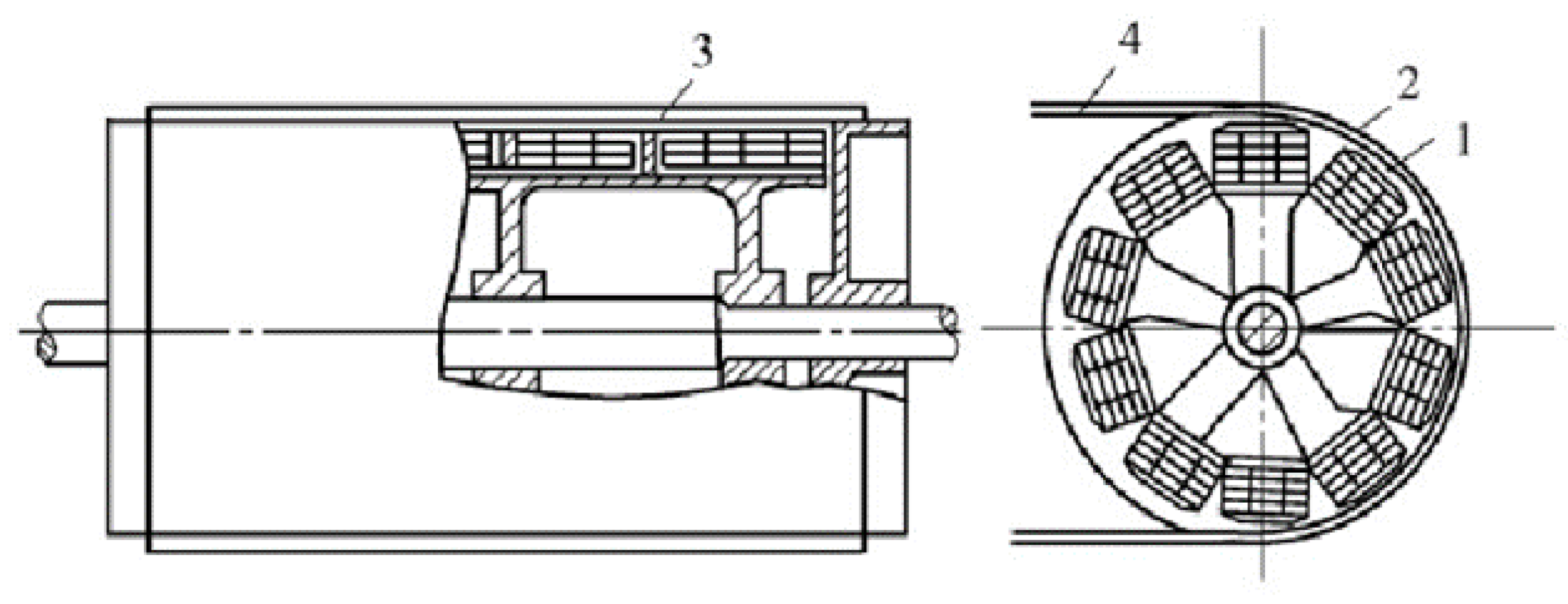
2.2. Dry Drum Magnetic Separator

In the 1980s, Ball-Nortony developed the first electromagnetic drum magnetic separator, which was then widely used for magnetic iron removal. In the late 1980s, following in-depth research on rare earth permanent magnetic materials and the magnetic system structure, the drum magnetic separator gradually realized permanent magnetization. The Swedish company Sala produced the first permanent magnetic drum magnetic separator in 1989 [16]. At present, manufacturers of drum-type magnetic separators are leaning toward the development of large-scale drums, high field strength, and multiple drums in series [17]. In the direction of large scale, Eriez Corporation (PA, USA) developed a magnetic separator, with a maximum drum diameter of 1219 mm and drum length of 3048 mm. Meanwhile, the magnetic separator developed by Sala Corporation (Västmanland, Sweden) has a maximum drum diameter of 1200 mm, drum length of 3000 mm, and equipment capacity of 500 t/h. The ROXON magnetic separator developed by Kern Engineering Company in Finland has a drum diameter of 1200 mm, drum length of 3000 mm, and equipment processing capacity of 400 t/h. The development of a larger dry magnetic separator can help improve the processing capacity and efficiency of the equipment and reduce its energy consumption [18]. In the direction of high field strength, some scholars began to study the magnetic circuit in the 1970s, published the first research on the magnetic circuit of a strong permanent magnetic field in 1974, and then developed the first medium-field strong permanent drum magnetic separator with a magnetic field strength of 0.5 T. Soon after, the second generation of permanent drum magnetic separators was developed with a magnetic field strength of 0.7 T [19]. Two types of magnetic system structures are commonly used in drum magnetic separators, namely the open magnetic system structure and the extruded magnetic system structure, as shown in Figure 2
The open magnetic system has a simple structure and is mainly used for the sorting of strongly magnetic ores. This system has two basic designs, called radial and axial configurations. In a radial configuration, the polarity of permanent magnets alternates across the drum width, whereas in an axial arrangement, the poles alternate along the circumference. The radial configuration is beneficial in the recovery of strongly magnetic material, whereas the axial configuration is used in situations where the grade of the concentrate is particularly important. The tumble motion of particles over the rows of the magnet with alternating polarity releases the entrained non-magnetic particles, hence improving the grade of magnetic concentrate. In addition, auxiliary poles can be added to the two main magnetic poles in the open magnetic system to generate field strength formed through the three poles superimposed in space and improve the strength and depth of action of the magnetic field. However, the magnetic lines of force in the open magnetic system are relatively scattered, thereby introducing challenges in achieving a very high magnetic field strength. At present, the magnetic field strength at the drum surface under this magnetic system structure cannot easily exceed 0.75 T, hence preventing the recovery of weak magnetic minerals, such as hematite and manganese ore [20,21]. By contrast, the emergence of the extruded magnetic system further increased the magnetic field strength on the surface of the drum. The principle of this system is to arrange the magnetic poles of the same polarity next to one another to concentrate the magnetic lines of force in a small space, and then export them through a magnetic conductive medium to produce a high magnetic field strength on this medium. However, the depth of the magnetic field action has insufficient depth. In the direction of multiple drums in series, the current frame structure of the drum magnetic separator is suitable for installing multiple drums to form two-, three-, and four-drum magnetic separators, thereby realizing the integration of roughing, selecting, and sweeping operations; improving the processing capacity of the equipment; shortening the process; and saving space. East and Mineral Processing Machine, Inc., in Japan developed the TY-6E-2 type magnetic separator, which comprises four magnetic drums in series, of which the first drum is used for coarse separation, the second drum is used for sweeping, and the third and fourth drums are used for concentration. Using this device to separate alluvial iron ore can obtain a concentrate grade of 57% to 61%. Meanwhile, the DA-BW and DA-3B magnetic separators manufactured by Mitsubishi Electric Corporation (Tokyo, Japan) and Mitsubishi Metals Corporation (Tokyo, Japan) are assembled with double and triple drums, respectively, which can greatly improve their processing capacity and sorting performance [22].
Although dry drum magnetic separators come in many types, their working principles are similar, and they are widely used for sorting magnetic ores. As shown in Figure 3, the CTG magnetic separator mainly comprises a drum, magnetic system, sorting box, feeder, and driving device. The sorting principle of this device is that when minerals reach the surface of the drum through the feeding device, the non-magnetic particles enter the tailing area under the action of gravity, centrifugal force, and friction, whereas the magnetic minerals are adsorbed on the surface of the drum due to magnetic force and fall into the concentrate area under the action of inertia and gravity when the drum rotates to the area without magnetic field [23]. Yin et al. [24] developed the CTG-1030 drum magnetic separator with a large magnetic wrap angle composite pole set and extruded magnetic system structure, which enhances both the magnetic field force and depth of magnetic field action on the drum surface. Using this device to sort raw ore with a magnetic iron content of 3% and particle size of < 3 mm can result in a good index of 11.40% concentrate grade, 0.7% tailing grade, and 80.29% recovery.

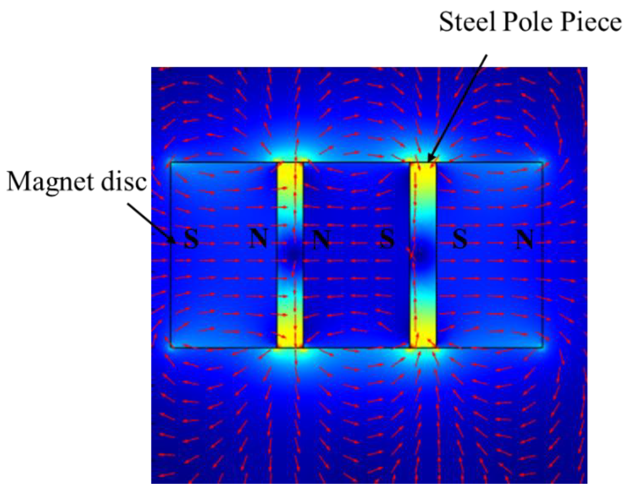
2.3. Dry Permanent Roll Magnetic Separator

The roll magnetic separator can be divided into electromagnetic induction roll and permanent roll magnetic separator according to the material of the magnetic system used. Compared with the electromagnetic roller magnetic separator, the permanent roll magnetic separator has more energy-saving features, a simpler structure, and a smaller floor space [25]. Due to the continuous development of rare earth permanent magnet materials in recent years, as shown in Figure 4, the surface magnetic field strength of the permanent roll magnetic separator can easily reach more than 1 T, thereby gradually replacing the electromagnetic induction roller [26].
Research on the permanent roll magnetic separator started as early as the 1970s, whereas related industrial applications began in the 1980s, starting from dry iron production from nonmetallic ores to the pre-sorting of weakly magnetic ores with coarse particle size [27]. The permanent roll magnetic separator comprises permanent magnet discs or rings interleaved with mild steel discs, as shown in Figure 5. Due to the specificity of the magnetic system structure, the magnetic field distribution of the separator is extremely uneven, and the magnetic line density on the roll surface is large, with high magnetic field strength and gradient [28].
Due to the rapid decay of the magnetic field strength on its surface, the roll magnetic separator is often used in conjunction with a thin belt. The separation principle of the roll magnetic separator is that the material is fed to the top of the belt and comes to the magnetic roller with the rotation of the belt, the magnetic particles are adsorbed on the surface of the magnetic roller and brought to the concentrate area, and the gangue is brought to the tailing area by centrifugal force and gravity, so as to realize the separation of magnetic material and gangue particles. The factors affecting the sorting performance of the roller magnetic separator can be categorized as follows: feed properties, design parameters, and operating parameters. The specific factors are shown in Figure 6 [29].
The magnet-to-steel disc thickness ratio (MSTR) is the key parameter of roll design that affects the strength and depth of the magnetic field. G.T. Mohanraj explored the magnetic field distribution of rolls with the help of the FEMM simulation software for different MSTRs. The simulation results are shown in Figure 7.
The results show that as the MSTR increases, the magnetic field gradient on the roll surface and the magnetic force on the magnetic particles both increase, but the magnetic field significantly decreases as distance increases. Sunil Kumar Tripathy [30] investigated the effect of magnetic roll parameters on the sorting of hematite with a fine particle size, and experimental results show that the magnetic field strength on the roll surface differs at the same MSTR (4:1, 8:2, and 12:3) but at different ring thicknesses of 1.05 T, 1.24 T, and 1.27 T, respectively. Gulsoy and Orhan achieved better iron removal for coarse-grained feldspar with a high MSTR in their test of feldspar removal with permanent magnet rolls [31]. The above results show that improving the MSTR and the thickness of magnetic and steel rings can help to enhance the magnetic field strength. The choice of MSTR is closely related to the properties of the material to be selected, and a suitable MSTR is conducive to improving the sorting effect of the separator.
Dry permanent roll magnetic separators are widely used to remove iron in non-metal ore or to pre-separate paramagnetic ore and have yielded good economic benefits. For example, the high-force permanent magnetic separator developed by INPROSYS, Inc., whose roll comprises 4 mm and 1 mm thick permanent magnetic rings and iron sheets arranged in a staggered manner, can reach a field strength of 2.2 T on the roll surface, but its field strength drops to 1 T at 2 mm from the roll surface. This separator handles a wide range of materials (about 20 mm to 0.074 mm) and has low energy consumption, requiring only a few watts of drive power, and a large processing capacity; thus, it has received wide usage in the United States, Australia, and Canada [32]. The Permroll permanent magnetic roll separator developed by Bettman Mining Equipment Supply Group, in South Africa, can reach a 1.2 T magnetic field strength on the surface of the roller, is light in weight (0.5 tons), consumes low power, processes a wide range of particle sizes (generally <3 mm), and is currently being sold to 25 countries [33]. Similarly, the CRIMM series permanent roll magnetic separator developed by the Changsha Institute of Mining and Metallurgy in China has a magnetic roller material made of neodymium (NdFe-B) and DT4 pure iron and can reach a magnetic roller surface field strength 1.4 T. This device also has a processing size range of 20 mm to 0.074 mm and processing capacity of 0.5 t/h–8 t/h. This device performs well in the selection process of Yunnan Huanian limonite ore in China; when the raw ore grade is 46%, a single sorting can obtain a concentrate grade of more than 50% and a more than 80% recovery rate [34]. The YCG series magnetic separators developed by the Maanshan Mining Research Institute in China have been used to address the limitations of coarse-grain permanent roll magnetic separators and are considered the ideal equipment for sorting coarse-grain weakly magnetic minerals. This device has a roll surface field strength that can reach 1.4 T and a processing particle size range of 75 mm to 6 mm. This device was used to modify the gravity separation plant of the Shanghai Meishan Mining Company in China and to replace the jigger. Results show that when the feed grade ranges from 24% to 26%, a concentrate grade ranging from 32% to 34% and a tailing grade ranging from 10% to 12% can be obtained after separation, which leads to the recovery of 85,000 tons of coarse concentrate more than the jigger in a year and a revenue of CNY 3.6 million [35].

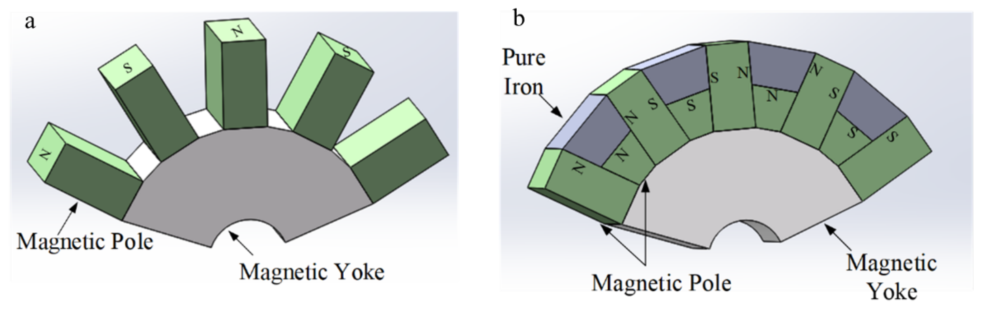
3. Dry Magnetic Separator with Improved Magnetic System

With the rapid development of rare earth permanent magnetic materials and agglomeration technology [36,37], the magnetic system can obtain high magnetic field strength without relying on electromagnetism, and the current dry magnetic separators have basically realized permanent magnetization. A magnet composed of NdFeB has the advantages of high magnetic field strength, simple structure, and low production energy consumption, but due to the high magnetic field strength, it easily produces the magnetic agglomeration effect, so the magnetic system design of this type of magnetic separator is often different from the conventional magnetic separator. For example, the CXY cylindrical rare earth permanent magnetic separator with a wiggling magnetic system designed by Xu et al. has a magnetic system made of NdFeB magnet material, and the magnetic induction of the drum surface is 0.3~0.8 T [38]. The most important feature of this device is that the magnetic system can oscillate back and forth. Therefore, the magnetic minerals slide on the surface of the drum when sorting, which makes the material become loose and effectively cleans sticky material. In addition, the dynamic magnetic field separator developed by Zhao et al. [39,40] uses asynchronous rotation between the magnetic system and the drum, which generates a high-frequency alternating magnetic field on the surface of the drum, making the tumbling times of mineral particles several times higher than the conventional magnetic separators, and this magnetic separator has achieved better results in the magnetic separation experiments of fine-grained minerals. In addition, Wang et al. [41] designed the CTFG-type powder ore dry magnetic separator. The sorting principle is shown in Figure 8. The drum and magnetic system rotate in reverse, and the magnetic chain rolls, shakes, and throws at high frequency on the drum, which greatly throws away the pebble particles entrapped in the powder ore.

4. Dry Magnetic Separator after Force Field Optimization

The TDMS demonstrates strong magnetic agglomeration in the sorting process, has serious gangue inclusions, and has a concentrate grade that is difficult to improve. Although a dry magnetic separator with an improved magnetic system can make the mineral particles tumble on the drum surface and improve the concentrate grade to a certain extent, the destruction of magnetic agglomeration is limited, and much room for improvement can still be observed. To better solve the magnetic agglomeration problem, a new magnetic separator based on the composite force field has become a hot spot in the current research and development of mineral processing equipment. Compound force field magnetic separators, which are based on the traditional magnetic separator, use the difference in the physical and chemical properties of magnetic and gangue minerals and introduce other force fields to destroy the magnetic agglomerates so as to achieve a better separation effect.

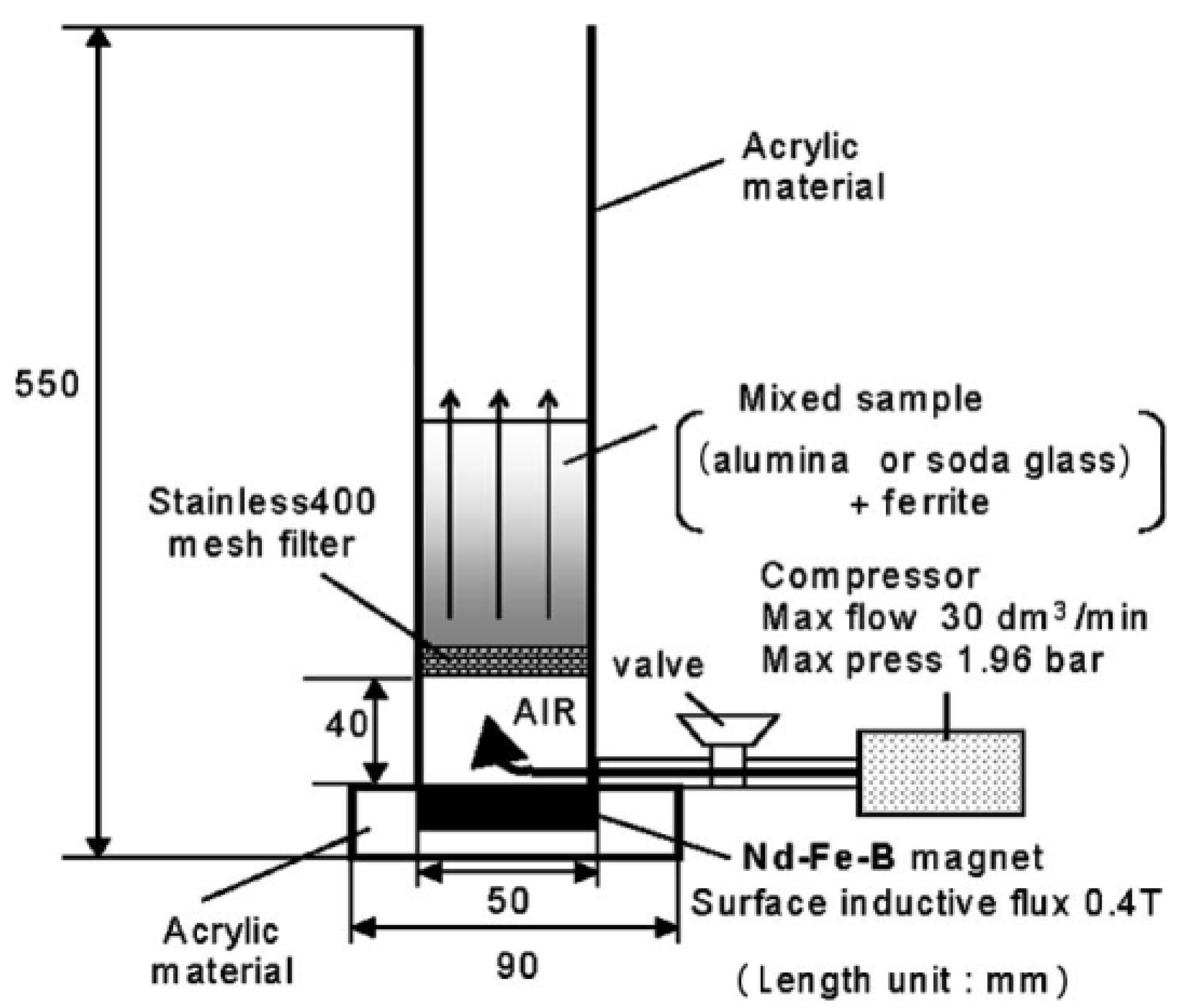
4.1. Open-Gradient Magnetic Separator

The air–solid fluidized bed technology is widely used in powder separation processes in chemical, pharmaceutical, agricultural, plastic, food, and other fields. The powder in the fluidized bed has liquid-like properties in terms of density and viscosity [42], and the separation of particles in an air–solid fluidized bed is similar to a re-election process, where the particles are in a floating state when the particle density is less than the fluidized bed density; otherwise, the particles sink. When the density difference of the particles in the fluidized bed is small, the separation process becomes difficult, whereas the fluidized bed magnetic separator takes advantage of the magnetic difference between the particles to separate the powder particles with a small density difference but a large magnetic difference. Fluidized bed magnetic separators are commonly used in the purification and recovery of heavy media (magnetite) in the dry coal separation process [43]. Figure 9 shows a dry open-gradient magnetic separator based on an air–solid fluidized bed developed by F. Mishima et al. [44]. The equipment mainly consists of a separator, a screen, a magnetic system, and an air compressor. When the separator starts sorting, the air provided by the compressor flows from the bottom to the top through the filter, which disperses the materials. At this time, the magnetic particles sink due to the strong magnetic force at the bottom, and the non-magnetic particles are in a floating state or blown out by the airflow. In this process, both the density and magnetic differences of the particles are exploited. Furthermore, the separation test results for mixed powder containing ferromagnetic particles show that increasing the magnetic field gradient in the equipment and optimizing the airflow in the separator can effectively reduce the sticky combination of agglomeration between powder particles and greatly improve the separation efficiency.

4.2. Dry Weak Magnetic Field Air Suspension Magnetic Separator

Cheng Kun [45] of Kunming University of Science and Technology in China developed an airflow-suspended dry magnetic separator, whose main sorting object is fine-grained materials. In this separator, the material enters the sorting space with the airflow from the bottom of the equipment so that the ore particles are in a loose state. The main structure of this separator includes ore feeding, air supply, piping, sorting, power regulating, and ore discharge systems. The working principle is shown in Figure 10. The main difference between this separator and others is that the sorting medium is changed from water to air, and the mineral powder is fed from the bottom feeding port and touches the drum surface with the airflow. Moreover, the outer part of the sorting cylinder is covered by a Plexiglas plate to prevent the mineral powder from being blown out. The mineral particles are subject to multiple forces, such as airflow traction, gravity, magnetic force, pressure gradient force, and Magnus effect lift force, in the sorting area. When the drum rotates, the magnetic particles are adsorbed on the surface of the drum because the magnetic force is greater than the combination force of other forces. Moreover, when the cylinder rotates to the concentrate port without wind, the magnetic particles adsorbed on the surface of the cylinder are scraped off by a scraper and enter the concentrate area. The non-magnetic particles are then discharged from the tailing port under the blowing of airflow. A comparison of these sorting results with those of a wet drum magnetic separator at the same ore size, feed rate, magnetic field strength, and other factors reveals that the concentrate grade is 1.91 percentage points lower than that of the wet magnetic separation, but the concentrate recovery is 0.61 percentage points higher; therefore, the separation effect of air suspension magnetic separator is comparable with that of wet magnetic separation.

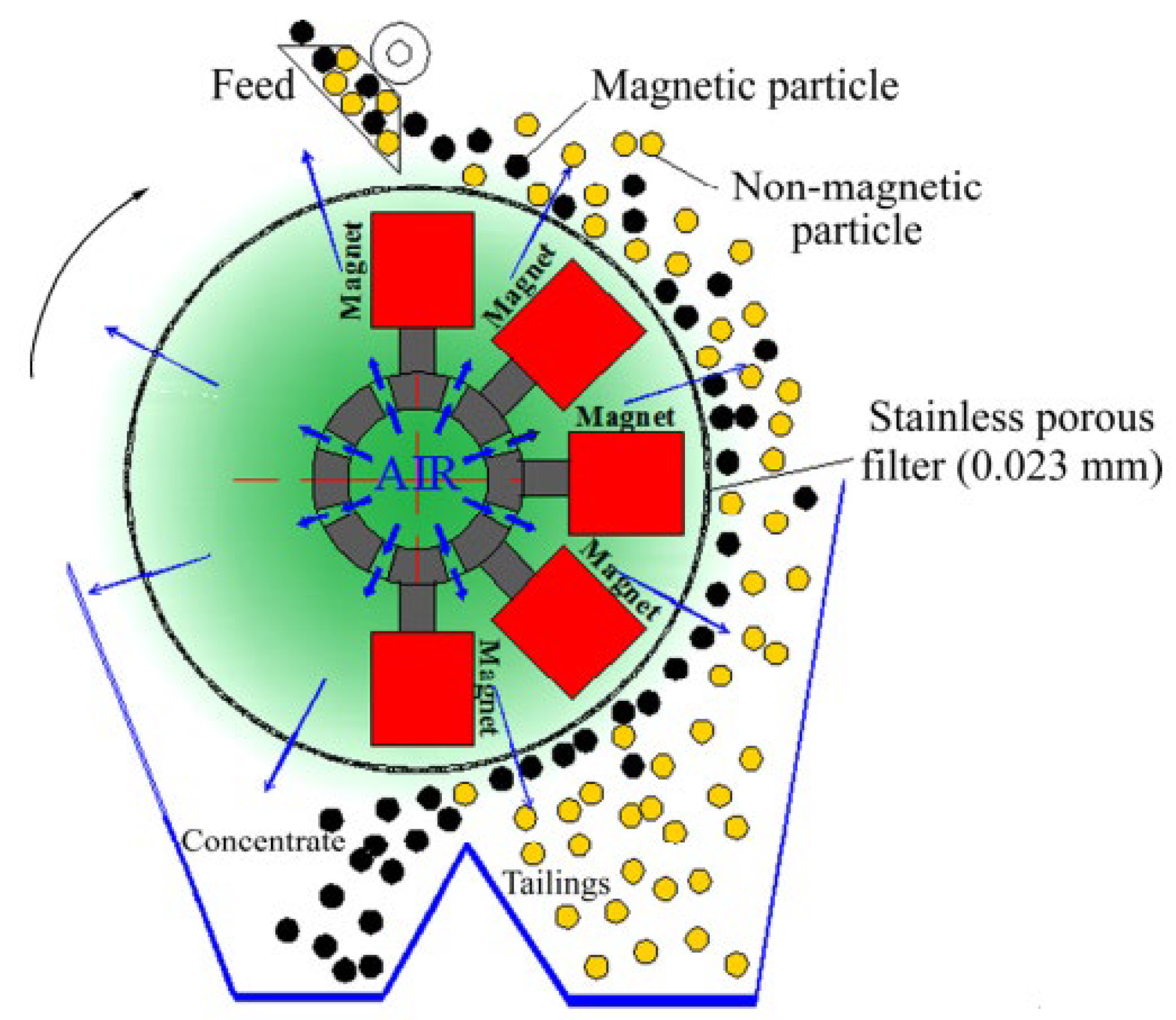
4.3. Dry Magnetic Separator for Pulverized Ore

Shandong Huate Magnetoelectric Technology Co., Ltd., developed a dry magnetic separator whose main sorting object is magnetite with a particle size of below 5 mm. The magnetic system is designed with a large wrap angle, multi-pole structure, a high magnetic field strength, a wider depth of action, and an adjustable drum rotation speed. Airflow is introduced on the drum surface to disperse the material. The separator structure is illustrated in Figure 11. When the separator works, the material arrives at the surface of the drum from the feed opening, where the magnetic minerals are magnetically adsorbed on the surface of the drum. As the drum rotates to the area without a magnetic field, magnetic minerals are separated from the drum surface and enter the concentrate area under the action of the unloading device, gravity, centrifugal force, and other competitive forces. At the same time, the non-magnetic materials and poor congeners are effectively removed under the joint action of magnetic pulsation and airflow and eventually enter the tailing area. The industrial test results of this magnetic separator reveal that the iron grade improved by 9.3 percentage points and that the recovery rate reached 90.85% after primary sorting using <1 mm KBH dephosphorized ore from South Africa. Then, the iron grade was improved by 3.77 percentage points and the recovery rate reached 95.02% after sorting using <2 mm of a certain iron ore from Hami, Xinjiang in China. When using this separator to sort a tailing from Xinjiang, China, the iron grade increased from 15.31% to 52.31% with a recovery of 12.71% [46]. These results show that the proposed dry magnetic separator for powder ore has a better sorting effect on ores in different areas and has strong applicability to the magnetic separation process in arid and water-scarce areas.

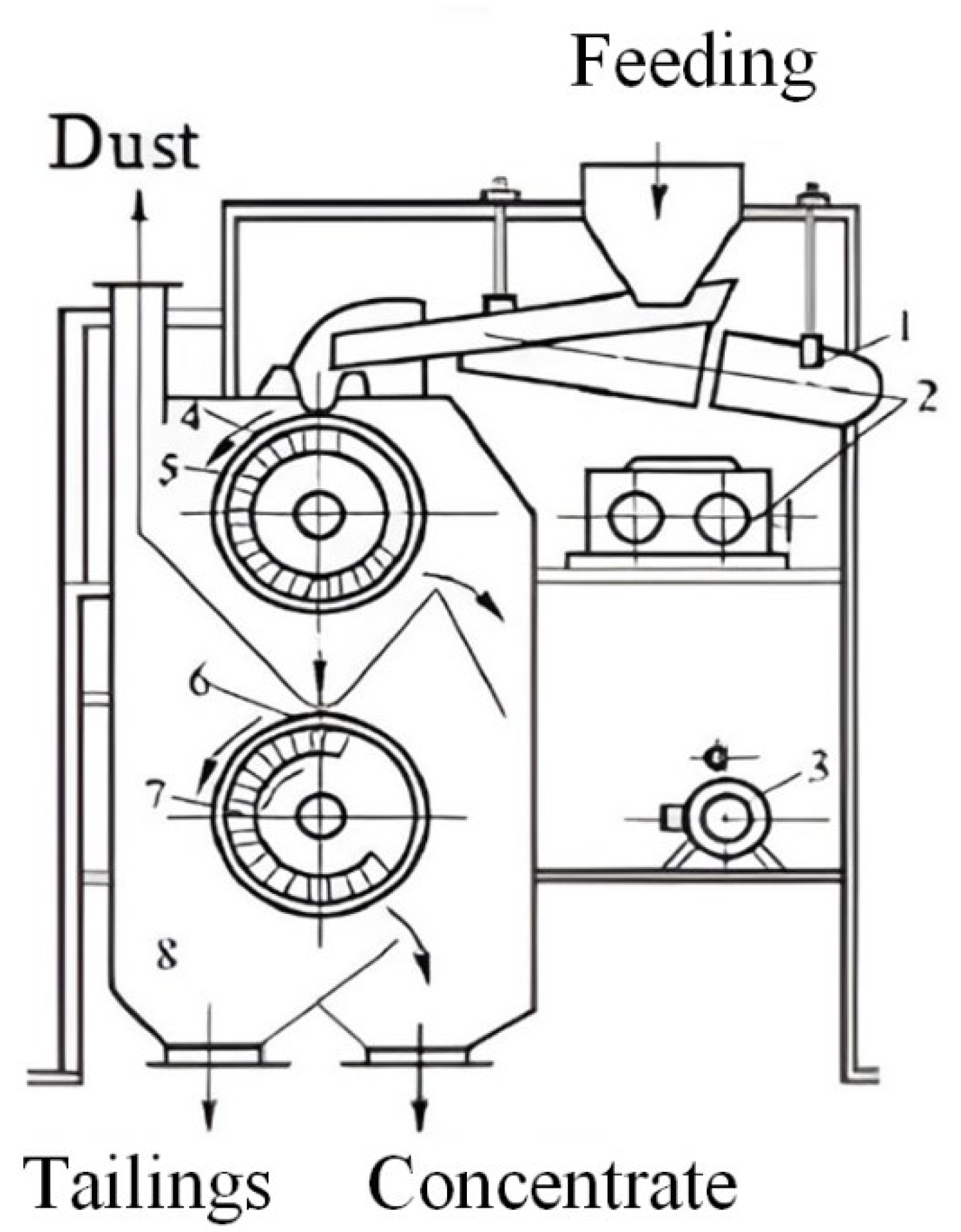
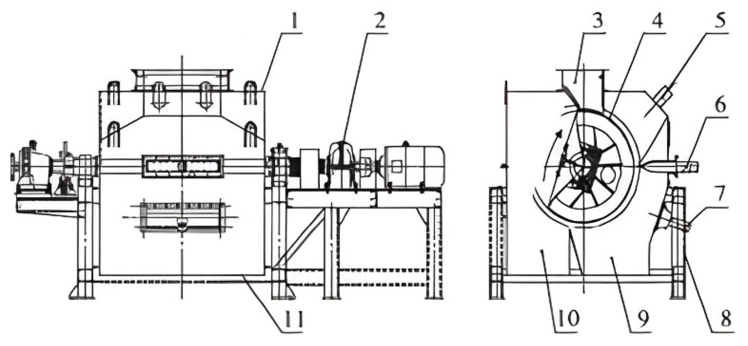
4.4. New Wind Dry Magnetic Separator

Lu [47] from Central South University in China developed a new magnetic separation device that uses the coupling effect of the air and magnetic fields to improve the traditional dry drum magnetic separator. This separator is mainly used for the pre-selection of fine-grained magnetite ore. The most important feature of this device is its use of an advanced airflow introduction method, where the airflow diffuses outward from inside the barrel through the micro-perforations on the barrel surface. This design maximizes the use of airflow traction to destroy the magnetic agglomerates, thereby greatly improving the selectivity of the device [48,49]. As shown in Figure 12, the device includes a feed opening, drum, and air feeding device. For its sorting principle, when the material is fed into the sorting cavity, due to the action of the air blowing from inside the cylinder, the gangue particle and poor congeners are blown away into the tailing tank, whereas the magnetic particles are adsorbed on the cylinder surface due to the action of magnetic force and then enter the concentrate tank as the drum rotates. The airflow maintains the favorable looseness of the material and rejects some entrapped concretions and quartz. A concentrate grade of 54.59% and a recovery of 71.75% were reported after using this device for the separation of <3 mm magnetite from Dahongshan, Yunnan [50].

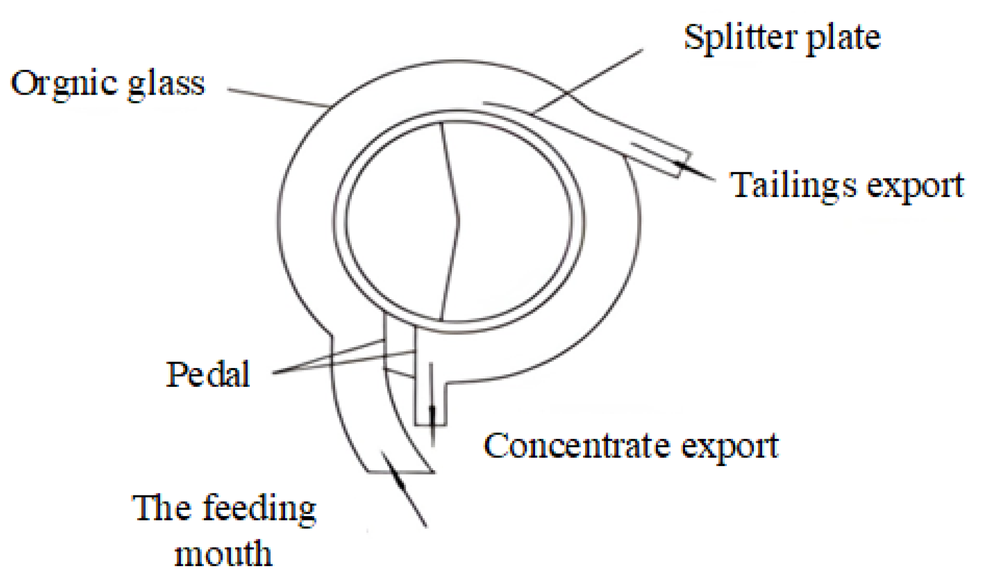
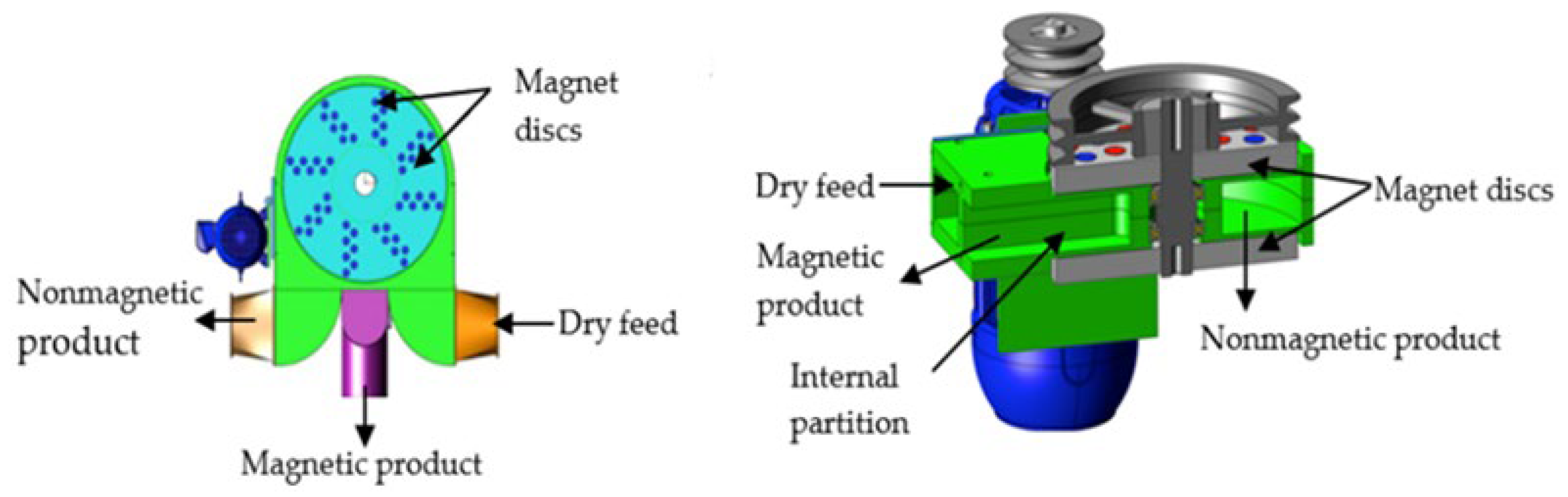
4.5. Pneumatic Planar Magnetic Separator

A new dry-type magnetic separator was developed by Baawuah et al. for the separation of fine-grained magnetite [51]. As shown in Figure 13, the components of this separator include: a non-magnetic housing forming a circular internal separation chamber, an inlet, a concentrate outlet, and a tailings outlet. The separation chamber consists of two discs with small circular magnetic blocks set at intervals as the magnetic field source. During sorting, the material and wind are fed together from the feed inlet, and the material maintains a good dispersion due to the airflow. After entering the sorting chamber, the magnetite is sucked onto the small magnetic blocks, and with the rotation of the disc, the magnetite on the disc surface is scraped off after entering the concentrate outlet, whereas the non-magnetic material is blown by the wind into the tailing outlet. The sorting effect of this device is close to that of a wet magnetic separator; thus, this device is expected to replace the wet magnetic separator in cold and water-scare areas.

5. Analysis Comparison

5.1. Comparison of Sorting Effect

Three types of separators, namely TDMS, MSIMS, and MSOFF are reviewed in this section based on their separation characteristics. These types of magnetic separators are mainly used in the realization of dry magnetic pre-selection technology, and their parameters and sorting results are shown in Table 1.
The main differences between these separators are reflected in the different lower limits of the selected particle size. Specifically, the TDMS is suitable for the pre-selection of bulk and coarse-grained magnetic materials by throwing out the surrounding rocks mixed in the mining process to restore the geological grade. This separator has minimal effects on concentrate grade improvement and is often used after coarse crushing operations, thereby reducing the load on the grinding operation. Meanwhile, the MSIMS is suitable for processing fine-grained magnetic ore. By increasing the magnetic tumbling number, so that the magnetic chain in the tumbling process breaks and the inclusions of locked particles and gangue can be thrown away, the MSIMS is commonly used in the pre-selection of products after the high-pressure roller mill fine crushing, but due to equipment space limitations, the improvement in magnetic tumbling is limited, and the tailing rate is low (generally 10%–20%). The MSOFF is always used to sort the product obtained by crushing and grinding to obtain coarse concentrate. This separator introduces airflow to disperse the agglomerated materials but can easily lead to cause excessive loss of conglomerate, hence reducing the recovery rate.
As mineral resources continue to deteriorate, their “poor, fine, and miscellaneous” characteristics have become increasingly significant. To economically exploit iron ore mining, dry magnetic pre-selection technology is essential. Given the fineness of the useful minerals embedded in particles, these particles need to be crushed or ground to throw off more qualified tailings. As the particle size decreases, the microscopic forces, such as van der Waals force, electrostatic force, and liquid bridge force, among the particles become increasingly significant, and the materials become prone to spontaneous agglomeration, thereby introducing difficulties in separation and requiring a separation accuracy from the dry magnetic equipment. TDMSs and MSLMSs are only suitable for the pre-selection of products after the crushing operation; the obtained iron ore concentrate grade is limited, and reaching 60% is difficult. Meanwhile, MSOFFs can be used in combination with the grinding operation because the introduction of airflow can improve the sorting accuracy to a large extent. By increasing the airflow rate, MSOFFs can obtain qualified concentrate products with an iron ore concentrate grade of over 60%. Therefore, this separator effectively copes with the current iron ore sorting dilemma and is expected to become a hot spot for future research and development of dry magnetic equipment.

5.2. Comparison of Sorting Mechanism

Magnetic separation selectively enriches the target component based on the magnetic difference of the sorted material. Upon entering an uneven magnetic field, the material becomes subject to the effect of magnetic and competitive forces. For those particles with strong magnetic properties, the magnetic force is greater than their competitiveness, and they will be adsorbed on the drum surface and enter into the concentrate product; for the particles with weak magnetic properties or non-magnetic properties, the competitiveness exceeds the magnetic force, and they will be thrown away from the surface of the drum and become the tailing product. To separate the material particles with different magnetism in the magnetic field, the necessary (but not sufficient) conditions can be expressed as follows:
F M > F C > F M *  
where FM is the magnetic force acting on the strong magnetic particles,   F M *   is the magnetic force acting on the weaker magnetic particles, and FC is the competitive force acting on the particles.
The TDMS and MSLMS have different equipment structures but the same sorting mechanisms. As shown in Figure 14, the particles are mainly subjected to magnetic force ( F M ) , centrifugal force ( F c ) , gravity ( G ) ,   and interaction force particles ( F A ) in the process. These parameters are calculated as follows.
F M = μ 0 · 4 π 3 R 3 · ρ s · x s · H · H
F c = 4 π 3 R 3 · ρ s · ω 2 · r
  G = 4 π 3 R 3 · ρ s · g
where: R—Particle radius, m.
ρ s —Particle density, kg/m3.
μ 0 —Vacuum magnetic permeability, N/A2.
x s —Specific magnetization coefficient, m3/kg.
H—Magnetic field strength, A/m.
∇H—Gradient of the magnetic field, A/m2
g—Gravitational acceleration, about 10 m/s2
ω—Drum angular velocity, rad/s
r—Drum radius, m
Figure 14. Dominant forces of the TDMS and MSIMS during their operation.
Minerals 12 01251 g014
In the sorting process of the abovementioned separators, the competitive force acting on the particles is generated by the rotation of the drum. Formula (3) shows that when the drum speed is certain, the centrifugal force is proportional to the third power of the particle size. As the particle size decreases, the particle interaction force increases, which means that a greater competitive force is required to achieve separation. Meanwhile, when the centrifugal force is sharply reduced, the relationship specified in Formula (1) cannot be satisfied. Therefore, the TDMS and MSLMS are not suitable for sorting micro-fine magnetic particles. However, the MSOFF additionally subjects particles to the drag force in the separation. The calculation formula and sorting force diagram(Figure 15) are presented as follows:
F d = 1 2 C D π R 2 ρ ¯ u 2
where: C D Fluid resistance coefficient.
ρ ¯ —Air density, kg/m3.
u—Relative motion velocity of mineral particles and airflow, m/s.
Figure 15. Dominant forces of the MSOFF during its operation.
Minerals 12 01251 g015
The forces acting on the particles during the sorting process can be categorized into radial and tangential forces. When the particles are adsorbed on the drum surface, they can be sent out along the tangential direction by the friction force to become concentrate. The tangential force affects the smooth movement of the particles to the discharge port, which is unfavorable to the capture process of magnetic materials. By contrast, the radial force effectively facilitates the separation process of the drum magnetic separator by absorbing or discharging the particles from the drum surface, which greatly affects the separation accuracy. Therefore, the radial force on the particles should be maximized, and the tangential force should be reduced during the sorting process. The MSOFF can also adjust the radial force of particles by controlling the flow rate of air to improve the trajectory difference between particles with different properties and enhance the separation accuracy of the separator. The strengthening effect varies depending on the angle between the drag force and the particle (θ). When θ is at (0, π), the drag force lies in the radial direction opposite to the magnetic force, which is conducive to the separation of magnetic materials from the gangue, thereby leading to a higher concentrate grade. To ensure the effectiveness of sorting, the following relationship should be satisfied:
F M > F D > F A
where F D is the drag force on the magnetic particles (N) and   F A is the interaction force between particles (N).
When θ is at (0,−π), the drag force in the radial direction is the same as that in the magnetic force direction, which is conducive to the adsorption of magnetic materials on the drum surface, thereby leading to obtaining a higher recovery rate. Airflow can also improve the dispersion of the material, thereby creating a favorable sorting environment for magnetic separation, based on the density difference between particles.
In a word, the biggest difference among the three abovementioned magnetic separators is that particles in their sorting chamber are subjected to different radial forces. The MSOFF adds more force in the radial direction of the drum than the TDMS and MSIMS. In the sorting of micro-fine particles of the material, the interaction between the particles and the magnetic agglomeration phenomenon is very significant. The centrifugal force can hardly provide competitive force, but the emergence of drag force can strengthen the force suffered by particles, thereby improving the selectivity of the dry magnetic separator.

6. Future Prospects

The literature shows that dry permanent magnetic separators have significant applications in mining iron ore, especially in cold and arid areas, and can even save on energy costs. However, several areas for improvement need to be addressed. First, the structure of the magnetic system (SMS) should be optimized according to the requirements of different operational processes. In the pre-sorting and rough sorting stages, the recovery of iron is most important. Therefore, the design principles of the SMS with a wide magnet block, large magnetic pole distance, and low number of particles tumbling are highly effective, whereas the SMS with a narrow magnet block and small magnetic pole distance is preferred over clean flowsheets due to its ability to increase the number of particles tumbling.
Second, the dry separator for pre-sorting of powder materials is generally lacking. In fact, the liberation degree of iron ore after grinding is high, which means that more gangue can be discarded by dry magnetic separators. Many researchers have tried to design a dry permanent separator used after the grinding operation with the help of air and reported some progress, but these separators are still in the laboratory stage due to their low recovery rate and unsatisfactory product quality. Optimization can be done in two ways to improve separator performance. On the one hand, higher-performance NdFe-B materials can be used in the magnetic system to ensure that a sufficient amount of magnetic force acts upon the magnetic particles. On the other hand, optimizing the flow field in the magnetic separator is very important. The flow field is directly related to the degree of particle dispersion, and a good dispersion guarantees the separator sorting accuracy. A uniform and smooth flow field not only improves the recovery rate and grade of concentrate but also adjusts the shape of the chamber and the position of the airflow inlet to control the distribution of the flow field.
It is hoped that in the future, more energy-efficient dry magnetic separators will be developed, and the iron ore in cold and arid areas can be effectively exploited.

7. Conclusions

  • With the growing depletion of iron ore resources, the application of dry magnetic separation technology is conducive to the early throwing away of unqualified tailings and reducing the amount of incoming mill, hence increasing the economic benefits for iron ore plants.
  • Dry magnetic separators can be categorized into TDMSs, DMSOMs, and DMSOFFs based on their structural characteristics. These separators also have widely divergent sorting characteristics. The TDMS, which is particularly suitable for coarse-grain iron ores, discards bulk gangue and improves the geological grade, but such grade improvement is small. The DMSOM, which is suitable for fine grains, discards fine gangue and obtains a rough concentrate. The DMSOFF, which is suitable for fine and micro-fine grains, discards tailings and exhibits higher accuracy than the TDMS and DMSOM in sorting micro-fine grain magnetic materials. However, the DMSOFF also allows a certain amount of ultrafine magnetic particles to enter the tailing products, resulting in a non-negligible iron loss.
  • Certain improvements in the structure of equipment, magnetic systems, and sorting force fields of dry magnetic separators have been reported in recent years.
The literature highlights the DMSOM as a current research hot spot that is expected to replace wet magnetic separators. However, research on this separator remains in the initial stage, and a comprehensive theoretical system has not been built yet. Therefore, the DMSOM still has a long way to go before its adoption in the industry. In the future, the coupling mechanism of the magnetic and flow fields and the optimization of the coupling method to realize an efficient utilization of airflow should be investigated in DMSOM research.

Author Contributions

S.X.; Conceptualization, methodology, investigation, validation, formal analysis, visualization, writing—original draft; writing—review and editing; Z.H.; formal analysis, writing—review and editing, supervision; D.L.; formal analysis, writing—review and editing, supervision, funding acquisition; Y.Z.; resources. All authors have read and agreed to the published version of the manuscript.

Funding

This research was founded by the National Natural Science Funds of China (Grant No. 52174270; 52174267; 51974366); Supported by the National Key Research and Development Program of China (No. 2021YFC2903202).

Conflicts of Interest

The authors declare no conflict of interest.

References

  1. Liu, X.; Chen, Q.; Wang, J. Development & practical use of technology of low-grade iron ore resource utilization. Min. Eng. 2009, 7, 25–28. [Google Scholar]
  2. Yin, J.; He, R.; Shen, K. An Application of Dry Magnetic Separation in an Iron Mine. Miner. Conserv. Util. 2006, 5, 31–33. [Google Scholar]
  3. Ran, H.; Shi, P.; Liu, Y. Present Status and Application Progress of Dry Magnetic Separation Equipment. Nonferrous Equip. 2010, 6, 11–13. [Google Scholar]
  4. Wei, N. Dry Magnetic Separation Practices in Production. Sichuan Non-Ferr. Met. 2014, 3, 18–21. [Google Scholar]
  5. Hu, Y. Research and Development of the Typical Magnetic Separators at Home and Abroad. Metal Mining. 2012, 9, 136–137. [Google Scholar]
  6. Zhu, Y. Problems and improvement of CTDG type large block dry permanent magnetic separator industrial test. Met. Min. 1995, 8, 51–52. [Google Scholar]
  7. Liu, B.; Zhu, Y.; Sheng, F. CTDG1220N type permanent magnet large block dry magnetic separator and its application. Met. Min. 2005, 4, 70–71. [Google Scholar]
  8. Chen, B.; Yan, W. Current status and development direction of research and application of weak magnetic separation equipment for iron ore. Miner. Compr. Util. 2007, 4, 34. [Google Scholar]
  9. Shang, H.; Zheng, H.; Shi, P.; Haijun, Z. Design and Application of CT-1627 Permanent Magnetic Pulley. Nonferrous Met. Miner. Process. Part 2012, 4, 31–34. [Google Scholar]
  10. Jiang, C. Trial discussion on some characteristics of dry magnetic separation. Yunnan Metall. 1985, 2, 22–26. [Google Scholar]
  11. Nakai, Y.; Mishima, F.; Akiyama, Y.; Nishijima, S. Development of high gradient magnetic separation system under dry condition. Phys. C Supercond. Phys. C Supercond. 2010, 470, 1812–1817. [Google Scholar] [CrossRef]
  12. Zhang, B.; Qu, J.; Lv, B. Development Status and Analysis of Magnetic Separation Equipments. Non-Ferr. Met. Miner. Process. Part 2011, S1, 155–158. [Google Scholar]
  13. Lu, B. Practical Application of Tailings Discarding Technology by Magnetic Pulley in Midi Concentrator. Min. Metall. Eng. 2014, 34, 61–63. [Google Scholar]
  14. Hantila, F.; Maricaru, M.; Popescu, C.; Ifrim, C.; Ganatsios, S. Performances of a waste recycling separator with permanent magnets. J. Mater. Process. Technol. 2007, 181, 246–248. [Google Scholar] [CrossRef]
  15. Liu, S. Research on Dry Preelction Discarding Tail Technique of Iron ore with Superfine Crushing[D]. Ms.c. Thesis, Henan University of Technology, Zhengzhou, China, 2012. [Google Scholar]
  16. Zhao, Y. New development of magnetic separation equipments. Metall. Mine Des. Constr. 1998, 1, 51–56. [Google Scholar]
  17. Han, W. Dissertion The Analysis and Design of Permanent Magnet Cylinder Magnetic Separator. Ms.c. Thesis, Hebei University of Technology, Tianjin, China, 2005. [Google Scholar]
  18. Feng, X. Analysis of the status and performance of foreign mining magnetic separation equipment. Coal Min. Mach. 1999, 1, 6–7. [Google Scholar]
  19. Zhang, Y. Analysis of Flow Field and Magnetic Field in the Separation Chamber of Dry Permanent Magnet Drum Separator. Ms.c. Thesis, Inner Mongolia University of Science and Technology, Baotou, China, 2020. [Google Scholar] [CrossRef]
  20. Ran, H. Development of permanent magnet strong magnetic separation technology. Non-Ferr. Met. Miner. Process. Part 2013, S1, 50–53. [Google Scholar]
  21. Cheng, L. Research of High Gradient Permanent Magnetic Drum Separator with Open Magnetic Circuit. Miner. Conserv. Util. 2019, 39, 14–17. [Google Scholar] [CrossRef]
  22. Feng, X. The current situation and analysis of foreign mining magnetic separation equipment. Coal Process. Technol. 1999, 1, 45–46. [Google Scholar] [CrossRef]
  23. Xie, S.; Wang, K. Structure and Application of CTG Dry Magnetic Separator. Min. Metall. 2007, 4, 71–73. [Google Scholar]
  24. Yin, X.; Ma, X.; Wang, X.; Yuying, W. Development and application of CTG-1030 permanent magnetic dry type magnetic separator. Mod. Min. 2013, 10, 154–155. [Google Scholar]
  25. Ibrahim, S.S.; Farahat, M.M.; Boulos, T.R. Optimizing the performance of the RER magnetic separator for upgrading silica sands. Part. Sci. Technol. 2017, 35, 21–28. [Google Scholar] [CrossRef]
  26. Svoboda, J.; Fujita, T. Recent developments in magnetic methods of material separation. Minerals Engineering 2003, 16, 785–792. [Google Scholar] [CrossRef]
  27. Andreachi, J.R.; Palasvirta, O.E. Magnetic Separator. Canadian Patent No. 711, 1965. [Google Scholar]
  28. Shi, C.; Zhang, Y.; Jiao, H.; Peng, L. Progress and analysis of roller type permanent magnetic separation equipment. Min. Eng. 2010, 8, 35–38. [Google Scholar]
  29. Mohanraj, G.T.; Rahman, M.R.; Joladarashi, S.; Hanumanthappa, H.; Shanmugam, B.K.; Vardhan, H.; Rabbani, S.A. Design and fabrication of optimized magnetic roller for permanent roll magnetic separator (PRMS): Finite element method magnetics (FEMM) approach. Adv. Powder Technol. 2021, 32, 546–564. [Google Scholar] [CrossRef]
  30. Tripathy, S.K.; Banerjee, P.K.; Suresh, N.; Murthy, Y.R.; Singh, V. Dry high-intensity magnetic separation in mineral industry—A review of present status and future prospects. Miner. Process. Extr. Metall. Rev. 2017, 38, 339–365. [Google Scholar] [CrossRef]
  31. Gulsoy, O.Y.; Orhan, E.C. Importance of magnet-steel configuration in dry high intensity permanent magnetic rolls: Theoretical and practical approach. Physicochem. Probl. Miner. Process. 2004, 38, 301–309. [Google Scholar]
  32. Wang, S.H.; Alvetson, B.R. A new type of rare earth permanent magnet strong magnetic separator. Foreign Met. Ore Benef. 1996, 10, 27–31. [Google Scholar]
  33. Hu, Y.; Ran, H. Development of Permanent Roll and Drum High-Intensity Magnetic Separators. Nonferrous Met. Miner. Process. Part 2019, 5, 114–118. [Google Scholar]
  34. Zhou, Y.; Li, X.; Yu, Z.; Zhongrong, L. Separation of limonite Using CRIMM Roll-type High Intensity Permanent Magnetic Separators-Productive Practice. Miner. Metall. Eng. 2002, 2, 62–64. [Google Scholar]
  35. Sheng, H. Development and application of roll-type High Intensity Permanent Magnetic Separator for Coarse Particals. In Proceedings of the 2004 National Academic Seminar and Technical Exchange Meeting on New Mineral Processing Technology and Its Development Direction, Jiangsu, China, August 2010; pp. 231–234. [Google Scholar]
  36. Arvidson, B.R.; Henderson, D. Rare-earth magnetic separation equipment and applications developments. Miner. Eng. 1997, 10, 127–137. [Google Scholar] [CrossRef]
  37. Chang, Y.; Wang, D.-P.; Li, W.; Pan, W.; Yu, X.-J.; Qi, M. Improved Electrical Insulation of Rare Earth Permanent Magnetic Materials With High Magnetic Properties. J. Iron Steel Res. Int. 2009, 16, 84–88. [Google Scholar] [CrossRef]
  38. Xu, J. Development of CXY Cylindrical Rare Earth Permanent Magnetic Separator with Wiggling Magnetic System. Diam. Abras. Eng. 2003, 2, 36–37. [Google Scholar]
  39. Zhao, H.; Ran, H.; Wang, X.; Wei, H. Development of a Dynamic Magnetic Field Separator. Nonferrous Met. Miner. Process. Part 2017, 5, 64–68. [Google Scholar]
  40. Zhao, R.; Shi, P.; Tian, H.-W.; Zhiguo, W.; Jianyi, Z. Development of Dry Magnetic Separator for Separating Fine Crushing Magnetite Ore. Non-Ferr. Met. Miner. Process. Part 2011, 5, 42–45. [Google Scholar]
  41. Wang, J.; Yuan, Z.; Sheng, H.; Guangyu, Z.; Shiqing, W. CTFG type dry magnetic separator for powder ore and its application. Mod. Min. 2017, 33, 159–161. [Google Scholar]
  42. Gelperin, N.I.; Einstein, V.G. Fluidization; Academic Press: London, UK, 1971; pp. 541–568. [Google Scholar]
  43. Song, S.; Zhang, G.; Luo, Z.; Lv, B. Development of a Fluidized Dry Magnetic Separator and Its Separation Performance Tests. Miner. Process. Extr. Metall. Rev. 2019, 40, 307–313. [Google Scholar] [CrossRef]
  44. Mishima, F.; Yamazaki, S.; Yoshida, K.; Nakane, H.; Yoshizawa, S.; Takeda, S.; Izumi, Y.; Nishijima, S. A Study on the Development of an Open-Gradient Magnetic Separator Under Dry Condition. IEEE Trans. Appl. Supercond. Publ. IEEE Supercond. Comm. 2004, 14, 1561–1564. [Google Scholar] [CrossRef]
  45. Cheng, K. Development of Dry Weak Magnetic Field Airflow Suspension Magnetic Separator. Ph.D. Thesis, Kunming University of Science and Technology, Kunming, China, 2007. [Google Scholar]
  46. Wang, S.; Xin, Q. Development and application research of a New Type of Dry Magnetic Separator for Pulverized Ore. Mod. Min. 2019, 35, 133–135. [Google Scholar]
  47. Liu, J.J. Research on Improving the Efficiency Magnetic Preselection of Fine-Grained Magnetite Based on the Synergetic Effect of Aerodynamic Field and Magnetic Field. Ms.c. Thesis, Central South University, Changsha, China, 2020; pp. 18–51. [Google Scholar]
  48. Lu, D.-F.; Liu, J.-J.; Cheng, Z.-Y.; Xudong, L. Development of an open-gradient magnetic separator in the aerodynamic field. Physicochem. Probl. Miner. Process. 2020, 56, 325–337. [Google Scholar]
  49. Liu, J.; Xue, Z.; Dong, Z.; Yang, X.; Fu, Y.; Man, X.; Lu, D. Multiphysics modeling simulation and Optimization of aerodynamic drum magnetic separator. Minerals 2021, 11, 680. [Google Scholar] [CrossRef]
  50. Liu, J.-J.; Lu, D.-F.; Wang, Y.-H.; Xudong, L. Effect of dry magnetic separator on pre-selection of magnetite under wind power. Chin. J. Nonferrous Met. 2020, 30, 2482–2491. [Google Scholar]
  51. Baawuah, E.; Kelsey, C.; Addai-Mensah, J.; Skinner, W. Assessing the performance of a novel pneumatic magnetic separator for the beneficiation of magnetite ore. Miner. Eng. 2020, 156, 106483. [Google Scholar] [CrossRef]
Figure 1. Schematic diagram of CT series magnetic pulley structure. 1—multipole magnetic system; 2—cylinder; 3—magnetic conductor; 4—belt [8].
Minerals 12 01251 g001
Figure 2. (a) Open magnetic system structure; (b) extruded magnetic system structure.
Minerals 12 01251 g002
Figure 3. Structure diagram of CTG permanent magnet double-barrel dry magnetic separator: 1—electric vibration feeder; 2—stepless governor; 3—electric motor; 4—upper roller; 5, 7—circular magnetic deficiency system; 6—lower roller; 8—box [23].
Minerals 12 01251 g003
Figure 4. History of magnetic materials used in permanent magnetic separators [26].
Minerals 12 01251 g004
Figure 5. Generation of magnetic field on a roll magnetic separator.
Minerals 12 01251 g005
Figure 6. The influences of rare earth roll magnetic separator process parameters [29].
Minerals 12 01251 g006
Figure 7. (a) Change in BB (force index) as a function of B2 for different M:S ratios; (b) change in magnetic force as a function of B2 for different M:S ratios [29].
Minerals 12 01251 g007
Figure 8. Separation principle of CTFG dry magnetic separator for fine ore [41] 1—vibration feeder; 2—ultra-thin transport belt; 3—tail wheel; 4—concentrate scraper; 5—concentrate bucket; 6—tailings bucket; 7—ore plate; 8—rotating magnetic system.
Minerals 12 01251 g008
Figure 9. Equipment for magnetic separation in dry process [44].
Minerals 12 01251 g009
Figure 10. Air suspension dry magnetic separator [45].
Minerals 12 01251 g010
Figure 11. Powder ore wind-driven dry magnetic separator [46]: 1—upper shell; 2—transmission device; 3—ore feeding port; 4—magnetic roller; 5—dust removal port; 6—air inlet device; 7—wind compensation device; 8—frame; 9—tailings mouth; 10—concentrate mouth; 11—the shell.
Minerals 12 01251 g011
Figure 12. New type of wind dry-type magnetic separator [50].
Minerals 12 01251 g012
Figure 13. Novel pneumatic planar magnetic separator [51].
Minerals 12 01251 g013
Table 1. Comprehensive summary of the dry permanent separators.
Separator TypeRepresentative
Equipment
Magnetic Field
Intensity
(Max)
Particle SizeMinerals UsedIndustrial/Laboratory Separating Results
TDMSCT1416 magnetic pulley0.328 T350 mmOre from Luzhong Metallurgical Mining Company (China)Can throw the tailings with a yield of 14% and increase the grade of the raw ore by 3% to 4%. Over a period of ten years, the separator saved about CNY 29.5 million in production costs.
CTG-1030 dry drum magnetic separator0.45 T<3 mmIron ore in Inner Mongolia (China)The magnetic iron content of the raw ore is 3%, and the grade of the concentrate after sorting is 11.4%.
YCG dry permanent magnetic roll1.4 T75–6 mmNanjing Meishan iron ore (China)The grade of raw ore is 24%–26%, and the grade of the concentrated product after beneficiation is 31%–38%; more than CNY 3.6 million per year is created by using this device.
MSIMSDynamic magnetic field separator0.2–0.45 T<20 mmA mine sample in Qian’an Hebei (China)The grade of raw ore is 23.26%, and the concentrate grade after beneficiation is 26.74%.
CTFG-type powder ore dry magnetic separator0.5 T<30 mmMagnetite in Lingqiu (China)The iron grade of the raw ore is 16.72%, and the concentrate grade is 21.51% after sorting.
MSOFFDry weak magnetic field air suspension magnetic separator0.18 T0.075 mm accounted for 87.7%Magnetite in Yunnan Province (China)The grade of raw ore is 46.15%, and the concentrate grade after separation is 60.78%.
Open-gradient magnetic separator0.4 T<0.045 mmFerrite particles mixed with ferromagnetic particles (Al2O3)The alumina separation efficiency was close to 100% when the particle size was relatively large (45 for alumina and 44 for ferrite).
Dry magnetic separator for pulverized ore0.3–0.6 T<1 mmDephosphorization product from KBH (South Africa)The grade of raw ore is 51.75%, and the concentrate grade after separation is 61.05% with 90.85% recovery.
New wind dry magnetic separator0.125 T<3 mmMagnetite ore from Yunnan Province (China)The grade of raw ore is 34.45%, and the concentrate grade after separation is 53.69% with 72.76% recovery.
Pneumatic planar magnetic separator0.2 T<0.075 mm accounted for 80%Magnetite ore (South Australia)The grade of the concentrate is 68.4% with 70% recovery after separating.
Publisher’s Note: MDPI stays neutral with regard to jurisdictional claims in published maps and institutional affiliations.

