Article

Hydrometallurgical Production of Electrolytic Manganese Dioxide (EMD) from Furnace Fines

by
Mehmet Ali Recai Önal
1,*,
Lopamudra Panda
2,
Prasad Kopparthi
3,
Veerendra Singh
3,
Prakash Venkatesan
4 and
Chenna Rao Borra
5
1
InsPyro N.V. Kapeldreef 60, 3001 Leuven, Belgium
2
Research & Development Group, Tata Steel Ltd., Kalinga Nagar 755026, India
3
Research and Development Division, Tata Steel Ltd., Jamshedpur 831001, India
4
Department of Materials Engineering, Synthesis and Recycling (4MAT), Université Libre de Bruxelles, 50 Avenue FD Roosevelt, CP165/63, 1050 Brussels, Belgium
5
Department of Metallurgical and Materials Engineering, Indian Institute of Technology–Kharagpur, Kharagpur 721302, India
*
Author to whom correspondence should be addressed.
Minerals 2021, 11(7), 712; https://doi.org/10.3390/min11070712
Submission received: 13 May 2021 / Revised: 23 June 2021 / Accepted: 25 June 2021 / Published: 1 July 2021
(This article belongs to the Special Issue Ferroalloy Minerals Processing and Technology)

Abstract

:
The ferromanganese (FeMn) alloy is produced through the smelting-reduction of manganese ores in submerged arc furnaces. This process generates large amounts of furnace dust that is environmentally problematic for storage. Due to its fineness and high volatile content, this furnace dust cannot be recirculated through the process, either. Conventional MnO2 production requires the pre-reduction of low-grade ores at around 900 °C to convert the manganese oxides present in the ore into their respective acid-soluble forms; however, the furnace dust is a partly reduced by-product. In this study, a hydrometallurgical route is proposed to valorize the waste dust for the production of battery-grade MnO2. By using dextrin, a cheap organic reductant, the direct and complete dissolution of the manganese in the furnace dust is possible without any need for high-temperature pre-reduction. The leachate is then purified through pH adjustment followed by direct electrowinning for electrolytic manganese dioxide (EMD) production. An overall manganese recovery rate of >90% is achieved.

1. Introduction

Manganese is an important raw material for steelmaking, batteries, fertilizers, catalysts, pigments, and non-ferrous alloys [1]. Manganese is the third most common constituent of steel, which is used as both a deoxidizer and an alloying agent. Typically, 7–10 kg of manganese-based ferroalloys (FeMn alloys) are required per ton of steel production [2]. Steelmaking, including its iron-making component, consumed more than 90% of mined manganese ores in 2013 [3].
Manganese dioxide (MnO2) occurs in nature as the mineral pyrolusite, which is about 62–63% manganese. The most important use of MnO2 is in primary Leclanché (carbon–zinc) and alkaline batteries. This material is used in obtaining the spinel structure of the cathode materials to be used in rechargeable Li-ion batteries (e.g., LiMn2O4) [4,5,6]. MnO2 needed for the production of batteries must have high purity and high electrochemical activity. Among its several allotropic forms, electrochemical activity is the highest for γ-MnO2. Hence, it is the best material for battery applications [7].
Since the early 2000s, the steady growth in demand for manganese dioxides has come from primary and secondary battery industries [8,9]. Three groups of manganese dioxides are being used in energy storage devices—namely natural (NMD), chemical (CMD), and electrolytic (EMD) manganese dioxide. The first type has been used in standard or Leclanché cells, whereas modern batteries, such as alkaline and lithium batteries, require the two synthetic forms with improved properties.
In terms of alkaline batteries, the use of EMD within the industry has exceeded 230,000 metric tons per annum, with a growth rate of about 10% annually [7]. With increasing global demand for batteries, the annual growth rate is expected to rise in the future. An additional increase in the demand for EMD is expected from the secondary, or rechargeable, battery market. This is mainly because lithium manganese ion batteries that use EMD in their manufacturing are replacing cobalt-type batteries as the cheaper and greener alternative. Manganese is being considered as a potential replacement for cobalt in the cathode material of lithium-ion batteries since it can increase safety and reduce cost, and it is environmentally more benign [10]. Growth is also likely to come from the use of EMD in hybrid electric vehicles [11].
It is possible to use a manganese ore to directly manufacture batteries so long as it meets specific characteristics and composition. This type of manganese dioxide is known as natural manganese dioxide, or NMD [12]. However, the demand for this material cannot be fulfilled through fresh ore only. The minimum and maximum concentrations for an ore suitable for Leclanché battery production is roughly 75–85 wt.% for MnO2 with 3–5 wt.% H2O, 0.5–5 wt.% SiO2, 0.2–0.3 wt.% Fe, and 0.1–0.2 wt.% for other metal oxides [13]. However, in alkaline, lithium, and other modern batteries, synthetic manganese dioxide with improved purity and quality becomes a must; therefore, it is necessary to produce it through chemical (CMD) or electrochemical (EMD) processes.
Conventionally, synthetic manganese dioxide is mainly produced from pyrolusite (MnO2) or rhodochrosite (MnCO3) ores. Pyrolusite ore has to be reduced before leaching, or it can be directly leached through a reductive leaching process [14]. After leaching and filtration, the leach liquor contains a variety of impurities, such as alkali metals, iron, nickel, and so on. Most of the iron present in the solution is removed through goethite precipitation by increasing the pH of the leachate to 2–3 with the addition of lime. Potassium and the rest of the iron are removed through further lime addition to maintain a pH level between 4–6 (i.e., jarosite precipitation). Mn does not precipitate until pH > 7 [15]. Ni, Cu, Mo, and other impurities that do not precipitate like Mn are removed through sulfide precipitation by adding Na2S or B2S [7]. After these purification steps, the manganese sulfate solution is forwarded to the electrochemical (for EMD) or chemical (for CMD) production step. The electrolysis process is more advantageous, as it produces MnO2 with better properties, regenerates acid, uses a smaller number of reagents, and generates fewer residues that may be harmful to the environment [7,12,16,17,18]. In EMD production, a purified leach solution containing around 150 g of MnSO4/L is used. Cell reactions are given in Equations (1)–(3) [19]. The voltammogram of EMD production exhibits an anodic current peak at about 1.3 V vs. SCE (MnO2 deposition), while a cathodic peak appears at 0.8 V vs. SCE.
at anode:
Mn2+ + 2H2O = MnO2 + 4H+ + 2e
at cathode:
2H+ + 2e = H2
overall:
Mn2+ + 2H2O = MnO2 + 2H+ + H2
Furnace dust is a problematic by-product of the ferromanganese (FeMn) and silicomanganese (SiMn) industries. Its storage is a long-term environmental concern, as it requires efficient technologies for its recycling [19]. The furnace dust contains high concentrations of manganese oxides, with up to 40% or more concentrate [20]. The recycling of the dust back into the ferroalloy furnaces would not only reduce that environmental liability but also decrease the fresh ore consumption. Unfortunately, this is not possible due to the high volatile content of furnace dust, along with its fineness. Many manganese ores contain substantial amounts of potassium (up to 2–3%). Much of this volatilizes and reports to the fume during the smelting operation [20]. The concern regarding the recycling of the fume is that volatile transition metals, such as zinc, can build up due to repeated recycling. One of Elkem’s submerged arc furnaces producing high carbon FeMn alloy had a severe eruption on December 9, 1992, due to an accumulation of volatiles which caused unstable structure formations in the furnace [21].
There is limited literature on the topic of recycling FeMn or SiMn furnace fines for manganese recovery, particularly through hydrometallurgical treatments. Nkosi et al. (2011) obtained a 49% Mn recovery rate from SiMn submerged arc furnace dust through direct atmospheric leaching using a diluted sulfuric acid solution [22]. de Arujo et al. (2006) studied the replacement of rhodochrosite ore by ferromanganese fines for the production of EMD [19]. The fines were directly digested in high concentrations of sulfuric acid, and the resultant solution was purified through pH adjustment first using NH3 (for iron removal) and then using a Na2S addition (for heavy metal removal). However, the study is mostly focused on the electrodeposition behavior of the purified digestion solution, with very little insight into the previous steps. Shen et al. (2007) and Hamano et al. (2008) proposed recycling routes for different dust samples generated by FeMn and SiMn production [23,24]. However, both studies only focus on the recovery of zinc that constitutes ≤1.5% of the dust. In this study, an alternative hydrometallurgical process is proposed for the utilization of FeMn furnace dust in the production of high purity electrolytic manganese dioxide (EMD). An experimental comparison is made between direct reductive leaching of the fines, using a novel, cheap, and green organic, and direct acid leaching.
It should be noted that, unlike the ores, the furnace dust is already in fine sizes, thus rendering the costly particle size reduction steps unnecessary. Its use to replace rhodochrosite (MnCO3) and pyrolusite (MnO2) for EMD production has other advantages too.
The concentrations of some undesirable impurities, such as Ni, Cu, and Mo, are smaller in the furnace dust than they are in the rhodochrosite ore. Although K and Na contents are significantly higher in the furnace dust, these elements do not affect the manganese dioxide electrodeposition. Furthermore, such fines do not generate CO2, which is formed through the reaction of carbonate present in the rhodochrosite ore.
In comparison to the pyrolusite ore, the furnace dust is already partially reduced during its formation. This means direct reductive leaching of the furnace dust is more beneficial, as less of the reductant will be needed than is needed for the ore. Compared to their inorganic counterparts, organic reductants are more preferable due to their environmentally friendly nature. Soluble organic compounds are the most suitable, compared to insoluble organic compounds, due to their faster reactivity. Sugar and glucose were found to be the most promising reductants [25]. However, in this study, dextrin—a water-soluble, organic reductant—is investigated as the cheaper organic alternative over sugar or glucose. The produced leachate is then purified conventionally, and the subsequent solution is used for conventional EMD production.

2. Materials and Methods

The furnace dust used in this study was obtained from the Ferro Alloy Plant (FAP) of Tata Steel in Joda, India. The entire sample was collected over a period of time in order to have an average chemical composition and phase distribution that might have varied by short-term differentiations in the furnace input materials. After sieved to −1 mm size, the entire sample was mixed thoroughly before preparing a representative sample. A part of the representative sample was taken for analyses using a coning and quartering technique. Chemical grade sulfuric acid, dextrin, and slaked lime (Ca(OH)2) were used in the present study.
A particle size analysis was carried out with the help of the wet sieving method. The chemical analysis of the samples was performed using a Spectro Analytical Instruments, Ciros model, inductively coupled plasma-optical emission spectrometer (ICP-OES) (SPECTRO Analytical Instruments Inc., Clive, Germany). The mineral phases of the samples were identified using a Panalytical X’pert Pro X-ray diffractometer (XRD) (Malvern Panalytical Ltd., Malvern, UK). The experimental parameters for XRD analysis were: 20–90 2-theta degree; radiation of CuKα; acceleration voltage of 40 kV; acceleration current of 30 mA; with a step size of 0.020 degrees. The phases present in the samples were also examined using a JEOL (Tokyo, Japan), an 840A model scanning electron microscope (SEM), equipped with an energy-dispersive X-ray detector (EDX).

2.1. Leaching Experiments

Leaching was performed in a conical flask on a magnetic stirrer that was fixed at 200 rpm throughout the study. 10 g of the dust sample was used in each experiment with a fixed solid: liquid ratio of 1:5 wt./vol. The acid amount was varied between 1M (8%) and 3M (24%). The dust sample was slowly added to the acidic solution with or without a reductive agent. The slow addition was due to the vigorous nature of the exothermic leaching reaction amplified by the fine particle size of the dust. To avoid material and heat loss, the flask was covered with aluminum foil or a watch glass throughout the leaching duration. The studied parameters and their ranges are summarized in Table 1.
After the leaching duration was completed, the solution was allowed to cool down. The sludge was rather gelatinous and hard to filter, possibly due to the presence of orthosilicic acid. The cooled solution was treated with lime addition to ease the filtration, which also helped neutralize the excess acid and remove the impurities. The lime-treated solution, with a pH of around 6, was quickly filtered with a funnel and filter paper. Since Mn precipitation does not occur up to pH 7–8, the loss of Mn to precipitation was minimal and was included in the overall Mn recovery rate [15]. The residue was washed 5 to 6 times to remove all the soluble manganese compounds. This final solution was used for electrolysis experiments.

2.2. Electrolysis Experiments

The electrolysis experiments were carried out in a cell consisting of a 250 mL beaker on top of a heating plate, two counter electrodes, one anode, a thermometer, and a DC power supply. Graphite was used for both electrodes. The cathode dimensions were 5 cm length, 1 cm width, and 0.1 cm thickness. The anode dimensions were 5 cm length, 2 cm width, and 0.1 cm thickness.
The electrolyte was prepared from purified leach solution and sulfuric acid. The solution temperature was maintained at 92 °C (±2 °C). The volume of the electrolyte was maintained through water addition during the experiment. The anode and counter electrodes were partially submerged in the electrolyte in order to maintain anode to cathode surface ratio of 2:1. After closing the cell, the synthesis of MnO2 was carried out with the help of a DC power supply. No external stirring was needed, as the hydrogen gas generated during the process created sufficient stirring in the solution.
Electrolysis was carried out at different current densities and acid concentrations to optimize the current efficiency. Different current densities (i.e., 0.5, 1, 1.5, 2, and 2.5 amp/dm2) were used with 0.5 mol of MnSO4 and 0.25 mol of acid-containing electrolytes. In the other set of experiments, different H2SO4 concentrations (from 0.05 to 0.45 M, with 0.1 intervals) were used. In all experiments, the electrolysis duration was fixed to 1 h. The weight of MnO2 deposited on the anode was noted after each experiment.

3. Results and Discussions

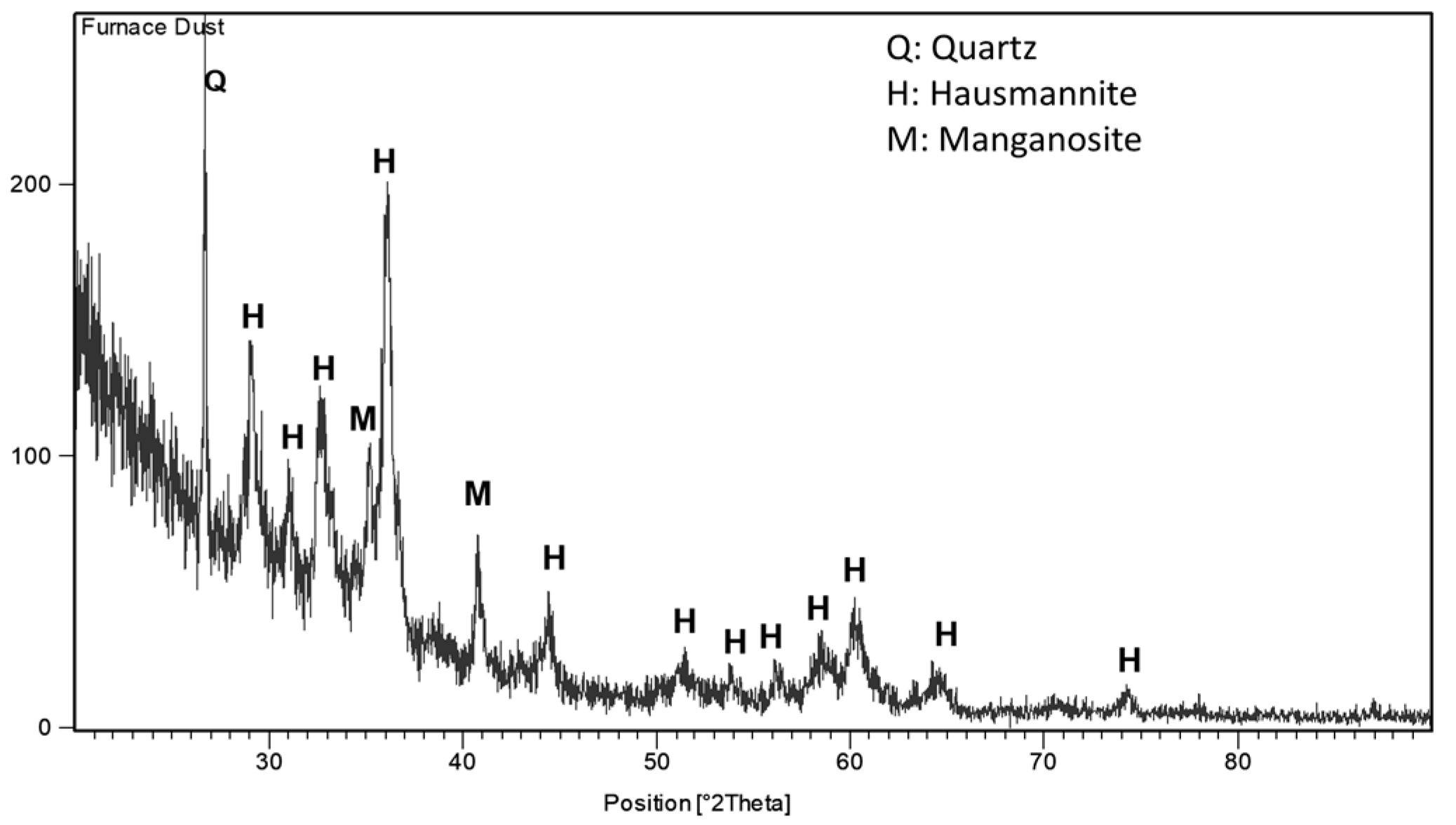
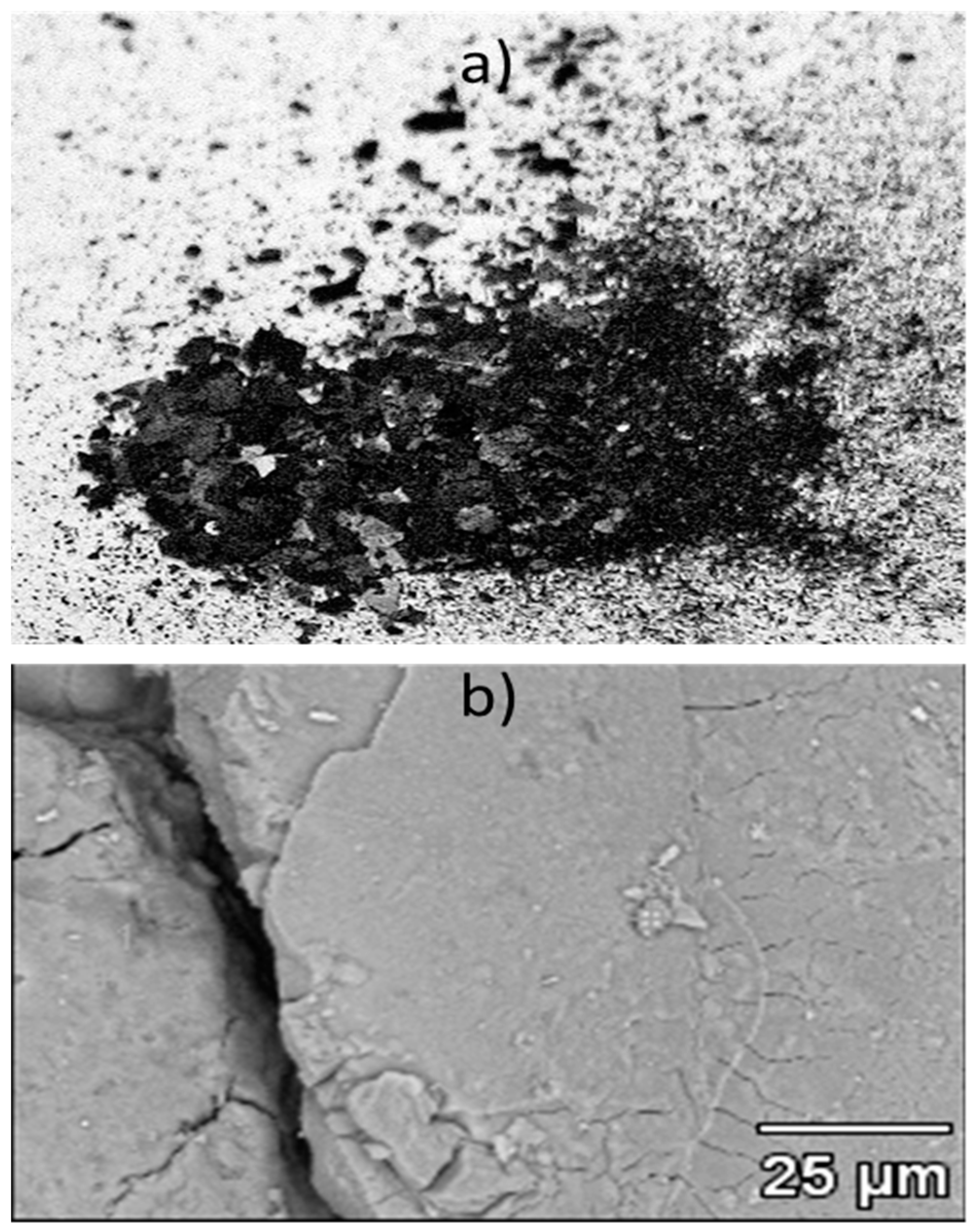
3.1. Characterization of Furnace Dust

The chemical analysis of the furnace dust used in the present study is provided in Table 2, and shows that the major constituents of the sample are Mn- and Si-based compounds. The XRD pattern of the furnace dust in Figure 1 shows three main compounds—namely, hausmannite (Mn3O4), manganosite (MnO), and silica (SiO2). The SEM micrograph of the furnace dust sample in Figure 2 shows that most of the furnace dust is less than 10 microns. The spot and area analysis indicated the presence of alkali metals, such as sodium, potassium, and barium.
A cumulative particle size analysis of the sample using the wet sieving method showed that >90% of the sample was less than 37 microns, and D80 of the sample was 32 microns. This shows that the furnace dust sample was such a fine material that further grinding would be simply redundant.

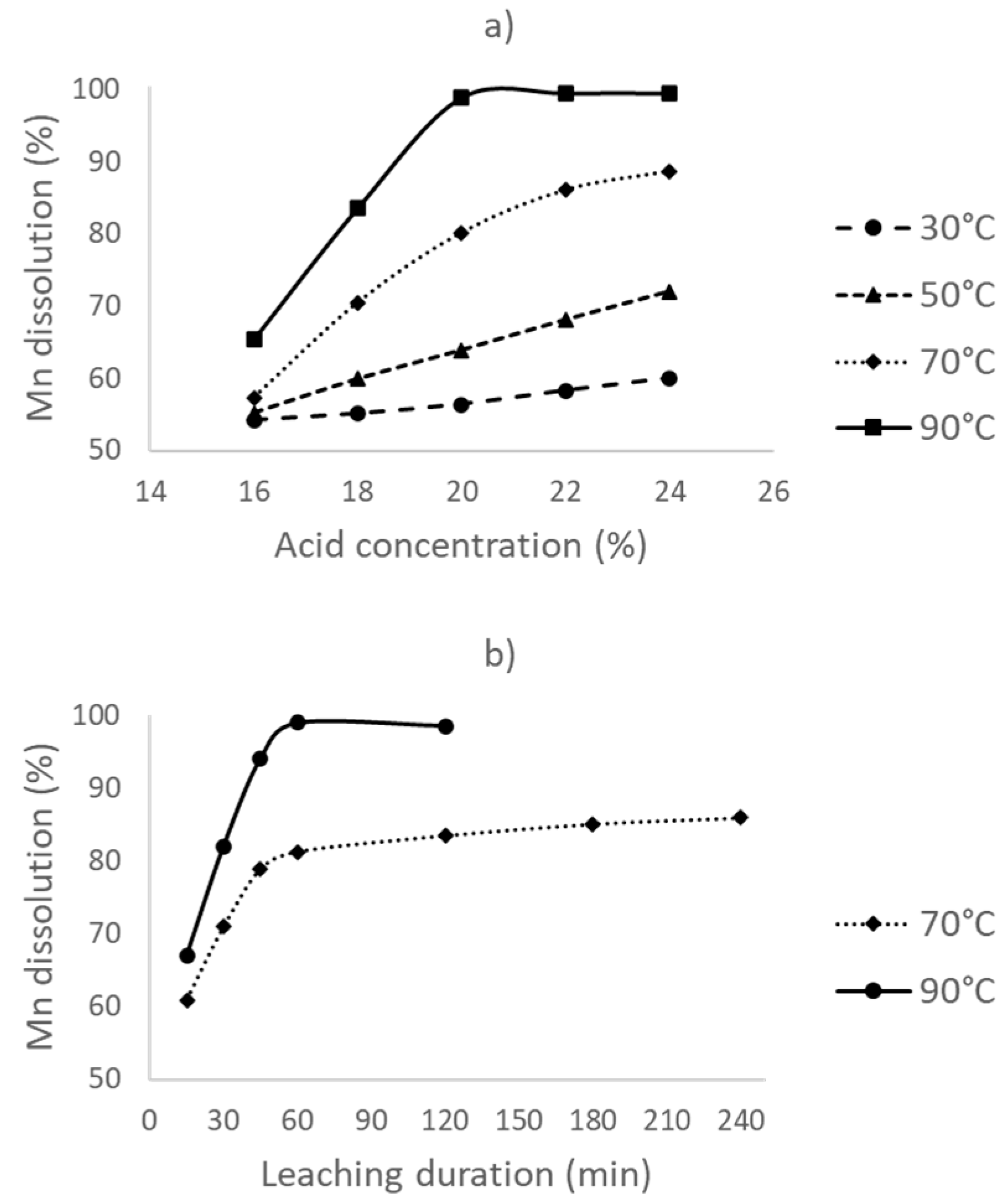
3.2. Leaching Experiments Without Reductant Addition (Direct Acid Leaching)

In the first part of the experiments, leaching was conducted without a reductant, at different leaching temperatures and acid concentrations, for a 1 h duration. The obtained results are provided in Figure 3a. The Mn dissolution rate increases to about 50% when the acid concentration is increased to 12%; however, it becomes stagnant thereafter, with a <10% increase at the highest acid concentration studied (20%). Meanwhile, manganese dissolution slightly increases with an increase in the leaching temperature. This may be due to the faster reaction of Mn with acid.
The initial drastic increase in the Mn dissolution rate is due to an increase in the availability of sulfuric acid. However, at higher acid concentrations, there is barely any soluble manganese form left. In all experiments, the Mn dissolution rate is less than 60%. This is due to the presence of Mn3O4 and MnO2 in the furnace dust sample. The Mn3O4 reaction with sulfuric acid is provided in Equation (4). From this reaction, it can be concluded that two parts of Mn3O4 present in the dust sample are soluble, and one part is insoluble. This is because the MnO2 present in the dust is completely insoluble in the sulfuric acid solution. This explains why the overall Mn recovery is less than 60%.
Mn3O4 + 2H2SO4 = 2MnSO4 + MnO2 + 2H2O
The effect of leaching duration on Mn dissolution was studied at different time intervals from 15 to 60 min, a 12% acid concentration, and a 30 °C leaching temperature. Figure 3b shows that, after the first half an hour, the dissolution rate of Mn reaches a maximum of about 48% and becomes stable despite the very fine particle size of the sample that improves the leaching kinetics. The optimized conditions for direct leaching are then found at a 30 °C leaching temperature, a 12% acid concentration, and a 30 min leaching duration.
The XRD analysis of the residue is provided in Figure 4. Only the silica and gypsum phases are clearly detectable. The calcium oxide present in the sample reacted with the sulfuric acid to create insoluble gypsum. There is no clear indication of any Mn-based compounds (e.g., MnO2) in the XRD pattern. However, the fresh and acid-insoluble MnO2 produced through the partial dissolution of Mn3O4 during leaching can still be present in the residue. Synthetic MnO2 typically has low-intensity and broad characteristic peaks [15]. Along with the fineness of the furnace dust that promotes the background noise, it is very likely that the amorphous and weak peaks of MnO2 that partly coincide with those of gypsum are dwarfed by the stronger peaks of the two crystalline phases.

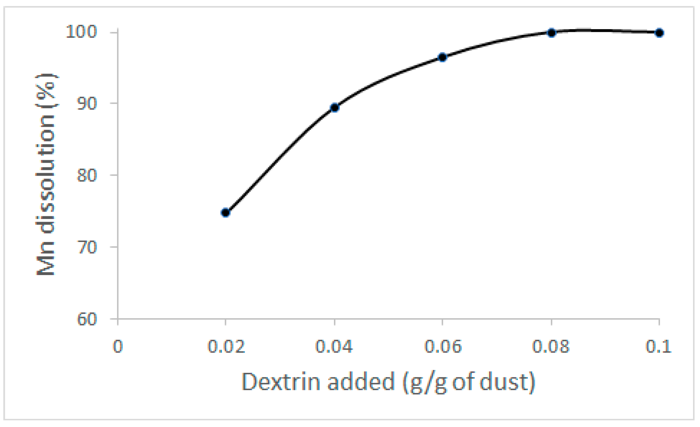
3.3. Leaching with Reductant Addition (Direct Reductive Leaching)

Through direct acid leaching experiments, it was found that maximum recovery of the manganese is less than 60% without any addition of a reductant. This is most likely due to the involvement of MnO2, which can only be effectively dissolved in sulfuric acid in a reducing atmosphere. In the second part of the leaching experiments, dextrin was added as the reductant. The amount of dextrin required for the complete reduction of manganese dioxide was calculated according to the reaction in Equation (5). Around 50% of the Mn present in the dust sample is soluble in acid without any reductant. Hence, the other half requires a reductant. Then, the stoichiometric need for dextrin was calculated as 0.05 g/g of dust (or 5% dextrin). However, for the initial studies, 50% excess or 0.08 g/g of dust (or 8% dextrin) was used to ensure sufficient dextrin presence. It should be noted that the reduction of MnO2 by dextrin (or the oxidation of dextrin by MnO2) is most likely not a single-step reaction. Previous studies showed that the acid leaching of the pyrolusite ore (MnO2) in the presence of carbohydrates, such as glucose (C6H12O6), lactose (C12H22O11), and sucrose (C12H24O11), results in intermediate reactions that provide intermediate degradation products, such as HCOOH and HCHO [25,26,27]. Based on this information, it is very likely that the same is valid for the case of dextrin, another carbohydrate.
12MnO2 + C6H10O5 + 12H2SO4 = 12MnSO4 + 17H2O + 6CO2
Figure 5a shows the effect of the leaching temperature and acid concentration on Mn dissolution in the presence of dextrin. To ensure that the amount of acid is sufficient in the case of a possible complete Mn dissolution, these experiments were conducted at more than 12% acid concentration. The results show that, with an increase in the leaching temperature, Mn dissolution increases; however, the temperature effect is more prominent at higher acid concentrations. The manganese dissolution rate is the highest for all acid concentrations studied when the leaching temperature is increased to 90 °C. This is possibly due to the increase in the reaction rate between dextrin and MnO2 Leaching efficiency also increases with increasing acid concentration. At low acid concentrations, this may be caused by the unavailability of the free acid that is consumed by both the direct and reductive leaching of manganese. With the addition of more acid, this problem should have been eliminated since, at 90 °C, the dissolution of Mn almost reaches completion with 20% acid concentration and is not affected by higher acid levels. Since acid concentrations of >20% will only consume high amounts of the neutralizing agent in the subsequent purification step, the optimum conditions for leaching become a 90 °C leaching temperature and a 20% acid concentration. Under these conditions, >95% of manganese can be dissolved into the solution.
To study the effect of leaching duration, sets of experiments were conducted at 70 and 90 °C with a 20% acid concentration and different time intervals. Leaching duration was varied from 15 min to 4 h, as shown in Figure 5b. With increasing leaching duration, Mn recovery drastically increases up to 1 h, and its effect becomes negligible with prolonged durations for both studied leaching temperatures. The time required for maximum Mn dissolution is higher for reductive leaching compared to direct leaching (i.e., with no reductant); this is due to the slower reaction between dextrin and MnO2. Lastly, to study the effect of the amount of reductant, experiments were conducted that varied the added dextrin amount at 90 °C for 1 h with a 20% acid concentration (Figure 6). With an increase in the concentration of dextrin, manganese dissolution increases; this is due to the increased availability of dextrin for MnO2 reduction. Maximum recovery of manganese (>95%) can be obtained with 8% dextrin addition (or 0.078 g/g dust). Hence, it is not possible to reduce the dextrin amount without losing Mn into the residue.
Sulfuric acid leaching of the furnace dust without a reductant can dissolve only <60% of manganese into the solution. The optimum conditions for leaching without a reductant are a 30 °C leaching temperature, a 12% acid concentration, and a 30 min leaching duration. Manganese dissolution can be improved through the addition of dextrin as a reductant. Mn dissolution of >95% can be obtained at 90 °C with a 20% acid concentration, a 1 h leaching duration, and an 8% dextrin addition.

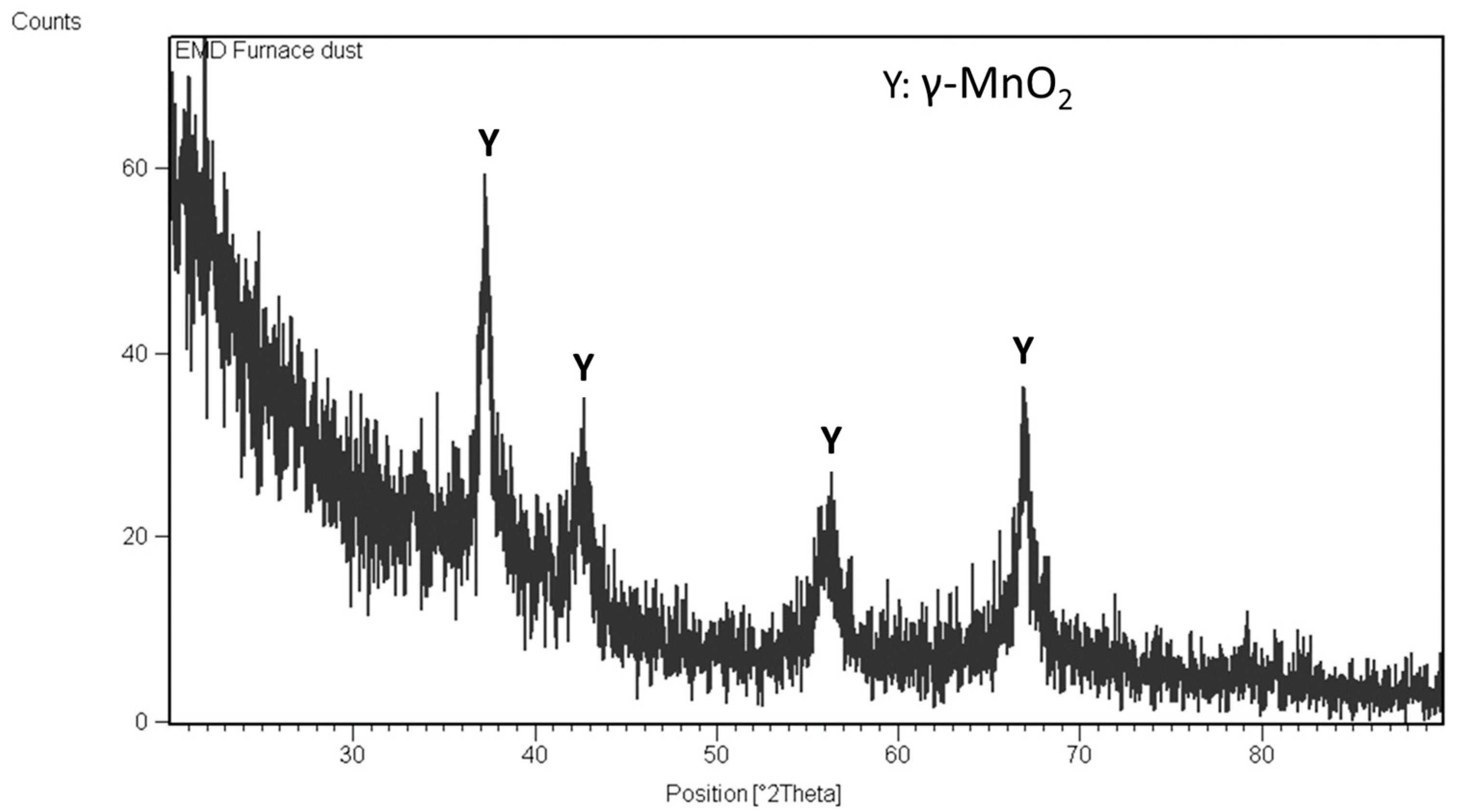
3.4. Electrolytic MnO2 (EMD) Production
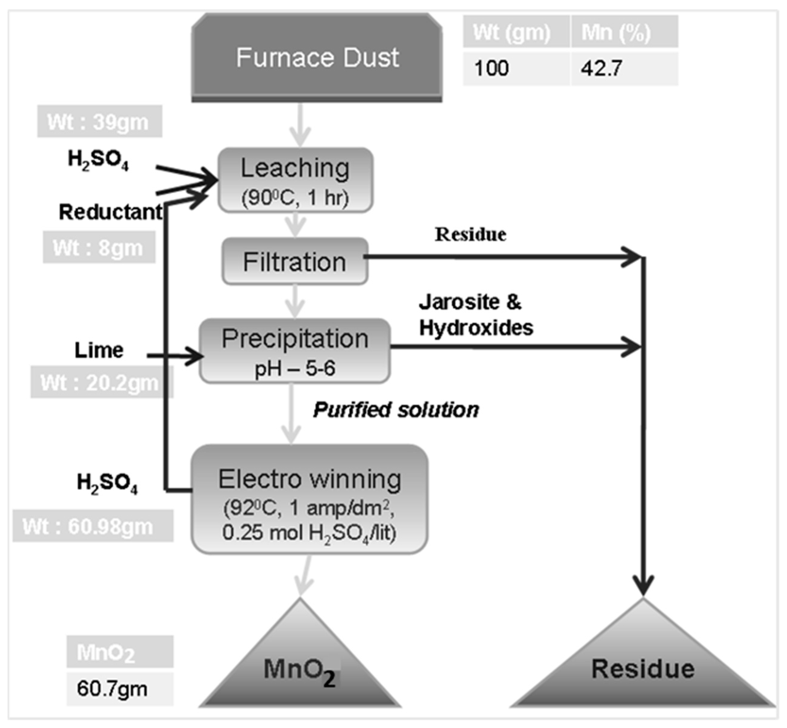
After almost complete leaching of manganese from the furnace dust, the manganese sulfate-rich solution can be used in the production of different end products. In this study, the leachate was used in the production of electrolytic manganese dioxide (EMD). However, further studies can investigate the use of furnace dust for chemical manganese dioxide (CMD) or manganese sulfate production. The latter is, for example, an important source for the secondary battery industry.
Figure 7a shows the effect of current density on current efficiency in a 0.25 M H2SO4 containing electrolyte. The current efficiency (CE) of the process is calculated based on Equation (6), where W, n, F, M, I, and t refers to the weight of MnO2 deposited, the number of electrons, the Faraday constant (96500 coulombs), the molecular weight of MnO2, the current in amperes (amps), and time in seconds, respectively.
C E = W n F M I t
From Figure 7a it can be seen that current efficiency increases with an increase in the current density to some extent, and it decreases gradually thereafter. Maximum current efficiency was obtained at 1 amp/dm2, which is generally used in conventional EMD processes. At higher current densities, the rate of MnO2 deposition is faster compared to the transport of ions. Moreover, the evolution of oxygen takes place at the anode due to the water-splitting reaction, which dominates over the MnO2 deposition.
The addition of sulfuric acid to the electrolyte is required in order to improve the conductivity of the solution. Figure 7b shows the effect of the concentration of sulfuric acid on the current efficiency of the process. The efficiency is slightly increased by increasing the acid concentration from 0.05 to 0.25 M. This is due to the sufficient availability of the ions, which improves current conductivity. Above that value, there is no effect of the amount of acid on the current efficiency.
The EMD powder produced at 1 amp/dm2 current density is shown in Figure 8a. In Figure 8b, the BSE image of the sample shows a rather smooth surface, with some cracks in the sample that developed during the mechanical removal of the deposit from the anode. The XRD pattern of the EMD powder is provided in Figure 9. It shows only the peaks of gamma-MnO2, which is suitable for battery applications. However, the bulk density measurement of the EMD powder is necessary in order to fully confirm this statement. In agreement with these results, the chemical analysis of the powder showed that all of the impurities were less than 0.1 wt.%.
Energy consumption (EC) during the process was calculated based on the formula in Equation (7), where V, I, t, and W refer to voltage in volts, current in amperes (amps), time in h, and the weight of the MnO2 deposited in kg, respectively. The energy required for the production of EMD powder was found to be in the range of 1.4–2.0 kWh/kg of MnO2 produced.
E C   ( kWh kg ) = V I t W
The overall flow sheet of the process is provided in Figure 10 with a partial mass balance. Based on 100 g of furnace dust input with 42.7% Mn, about 61 g of electrolytic MnO2 can be produced, which corresponds to an overall Mn recovery rate of 90.3% from the dust sample.

4. Conclusions

Ferromanganese furnace dust is an environmentally problematic by-product of FeMn alloy production. This study shows the feasibility of battery-grade electrolytic MnO2 production from a real furnace dust sample. The main conclusions of the study are:
  • The particle size of the dust (D80) was 32 microns. The XRD result of the furnace dust revealed that Mn3O4, MnO, and silica phases were present in the sample. Mn content was 42.7%.
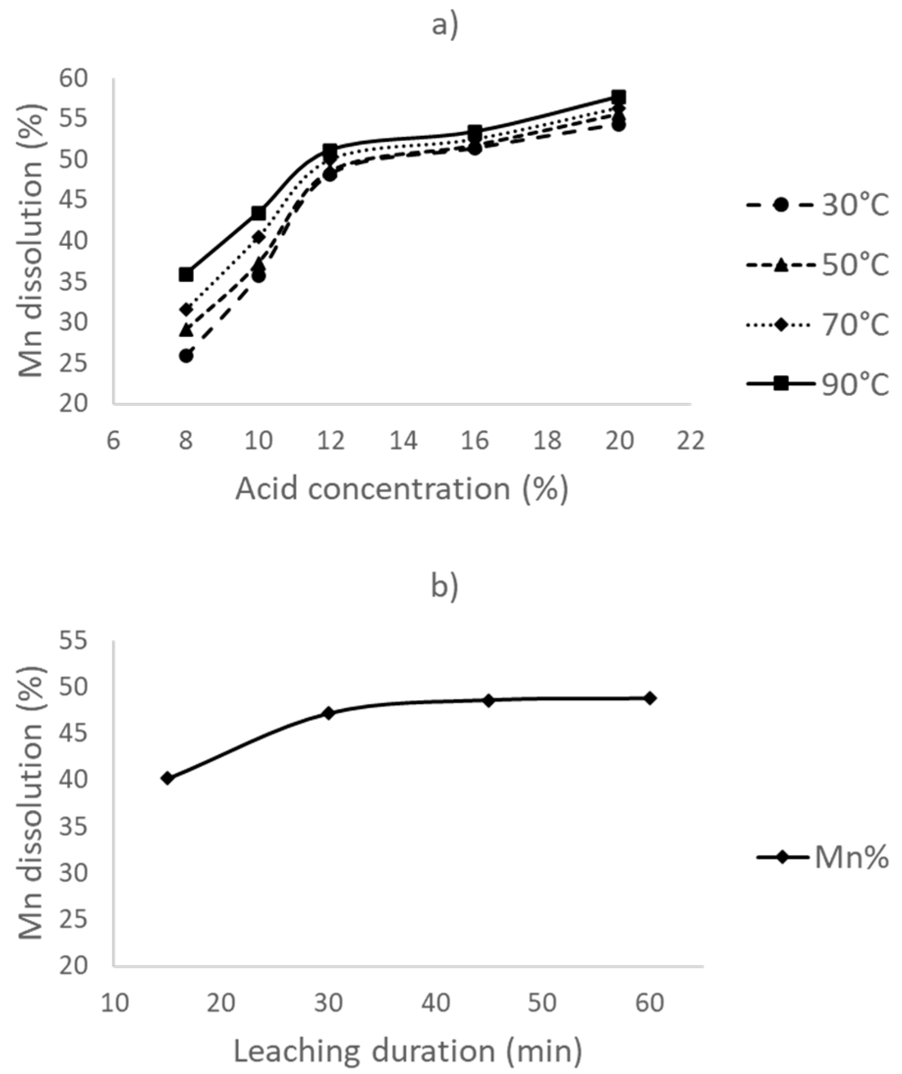
  • The leaching of the furnace dust without a reductant resulted in <60% Mn dissolution, with a 12% acid concentration, a 30 °C leaching temperature, and a 30 min leaching duration.
  • Dextrin, a green, cheap, and water-soluble organic reductant, was found suitable as a reductant.
  • 98.9% Mn dissolution is obtained by the optimum leaching conditions of a 90 °C leaching temperature, a 1 h leaching duration, a 20% acid concentration, and an 8% dextrin addition.
  • Optimized conditions for electrolytic manganese dioxide (EMD) production were: a current density of 1 amp/dm2 and a sulfuric acid concentration of 0.25 M. The product obtained through the electrolysis process is a pure gamma MnO2 phase.
  • A total manganese recovery of 90.3% from the furnace dust is possible with the proposed flow sheet.

Author Contributions

Conceptualization, M.A.R.Ö. and C.R.B.; methodology, C.R.B.; software, C.R.B.; validation, M.A.R.Ö., C.R.B., P.V., L.P., P.K., V.S.; formal analysis, C.R.B., L.P., V.S., P.K.; investigation, L.P., P.K., V.S.; resources, L.P., P.K., V.S.; data curation, C.R.B.; writing—original draft preparation, M.A.R.Ö.; writing—review and editing, M.A.R.Ö., P.V., C.R.B.; visualization, M.A.R.Ö.; supervision, C.R.B.; project administration, C.R.B. All authors have read and agreed to the published version of the manuscript.

Funding

This research received no external funding.

Acknowledgments

Investigators are thankful to M.B. Denys, (RD&T, India), and Rajeev Singhal, EIC (FAMD), for providing an opportunity to work on this project. Thanks are also due to V. Tathavadkar, Head (IFA Research Group); A.K. Lahiri; B.D. Nanda; and B.N. Rout, FAP Joda, for providing valuable inputs. Special thanks are also to Ranjeet Singh, R&D, for his help while conducting the test work.

Conflicts of Interest

The authors declare no conflict of interest.

References

  1. Sharma, T. Physico-chemical processing of low grade manganese ore. Int. J. Miner. Process. 1992, 35, 191–203. [Google Scholar] [CrossRef]
  2. Corathers, L.A. U.S. Geological Survey (USGS) Minerals Yearbook: Manganese; US Geological Survey: Reston, VA, USA, 2005.
  3. Elliott, R.; Coley, K.; Mostaghel, S.; Barati, M. Review of Manganese Processing for Production of TRIP/TWIP Steels, Part 1: Current Practice and Processing Fundamentals. JOM J. Miner. Met. Mater. Soc. 2018, 70, 680–690. [Google Scholar] [CrossRef]
  4. Kronenberg, M.L.; Blomgren, G.E. Primary Batteries—Lithium Batteries. In Comprehensive Treatise of Electrochemistry; Bockris, J.O., Conway, B.E., Yeager, E., White, R.E., Eds.; Springer: Boston, MA, USA, 1981; pp. 247–278. ISBN 9781461566892. [Google Scholar]
  5. Sattar, R.; Ilyas, S.; Kousar, S.; Khalid, A.; Sajid, M.; Bukhari, S.I. Study on the reduction roasting of spent LiNixCoyMnzO2 lithium-ion battery cathode materials. Environ. Eng. Res. 2020, 25, 88–95. [Google Scholar] [CrossRef] [Green Version]
  6. Munir, H.; Srivastava, R.R.; Kim, H.; Ilyas, S.; Khosa, M.K.; Yameen, B. Leaching of exhausted LNCM cathode batteries in ascorbic acid lixiviant: A green recycling approach, reaction kinetics and process mechanism. J. Chem. Technol. Biotechnol. 2020, 95, 2286–2294. [Google Scholar] [CrossRef]
  7. Biswal, A.; Tripathy, B.C.; Sanjay, K.; Subbaiah, T.; Minakshi, M. Electrolytic manganese dioxide (EMD): A perspective on worldwide production, reserves and its role in electrochemistry. RSC Adv. 2015, 5, 58255–58283. [Google Scholar] [CrossRef]
  8. Zhang, W.; Cheng, C. Manganese metallurgy review. Part I: Leaching of ores/secondary materials and recovery of electrolytic/chemical manganese dioxide. Hydrometallurgy 2007, 89, 137–159. [Google Scholar] [CrossRef]
  9. Biswal, A.; Dash, B.; Tripathy, B.C.; Subbaiah, T.; Shin, S.M.; Sanjay, K.; Mishra, B.K. Influence of alternative alkali reagents on Fe removal during recovery of Mn as Electrolytic Manganese Dioxide (EMD) from Mn sludge. Hydrometallurgy 2013, 140, 151–162. [Google Scholar] [CrossRef]
  10. Zhu, L.; Bao, C.; Xie, L.; Yang, X.; Cao, X. Review of synthesis and structural optimization of LiNi1/3Co1/3Mn1/3O2 cathode materials for lithium-ion batteries applications. J. Alloys Compd. 2020, 831, 154864. [Google Scholar] [CrossRef]
  11. Chow, N. Manganese ore for lithium batteries. Met. Powder Rep. 2012, 67, 34–36. [Google Scholar] [CrossRef]
  12. Biswal, A.; Sanjay, K.; Ghosh, M.K.; Subbaiah, T.; Mishra, B.K. Preparation and characterization of EMD from manganese cake—A byproduct of manganese nodule processing. Hydrometallurgy 2011, 110, 44–49. [Google Scholar] [CrossRef]
  13. Taucher, W.; Kordesch, K. Alkaline manganese dioxide-Zinc batterdes primary and rechargeable cells with and without mercury. Stud. Environ. Sci. 1994, 59, 163–202. [Google Scholar] [CrossRef]
  14. Ghosh, S.; Mohanty, S.; Akcil, A.; Sukla, L.B.; Das, A.P. A greener approach for resource recycling: Manganese bioleaching. Chemosphere 2016, 154, 628–639. [Google Scholar] [CrossRef]
  15. Önal, M.A.R.; Borra, C.R.; Guo, M.; Blanpain, B.; Van Gerven, T. Hydrometallurgical recycling of NdFeB magnets: Complete leaching, iron removal and electrolysis. J. Rare Earths 2017, 35, 574–584. [Google Scholar] [CrossRef]
  16. Rodrigues, S.; Munichandraiah, N.; Shukla, A.K. A cyclic voltammetric study of the kinetics and mechanism of electrodeposition of manganese dioxide. J. Appl. Electrochem. 1998, 28, 1235–1241. [Google Scholar] [CrossRef]
  17. Harris, M.; Meyer, D.M.; Auerswald, K. The production of electrolytic manganese in South Africa. S. African Inst. Min. Metall. 1977, 77, 137–142. [Google Scholar]
  18. Banerjee, T.; Chakrabarti, H.K.; Kar, B.C.; Dhananjayan, N. Electrolytic Manganese & Manganese Dioxide from Low-grade Indian Ores. Indian Min. J. 1957, 69–75. [Google Scholar]
  19. de Araujo, J.A.M.; de Castro, M.M.R.; Lins, V.F.C. Reuse of furnace fines of ferro alloy in the electrolytic manganese production. Hydrometallurgy 2006, 84, 204–210. [Google Scholar] [CrossRef]
  20. Matricardi, L.R. Disposal of ferromanganese furnace fume. In Proceedings of the Electric Furnace Conference, Houston, TX, USA, 9–12 December 1975; pp. 73–75. [Google Scholar]
  21. Lee, Y.E.; Kozak, D.S. The role of zinc in the eruption of high carbon FeMn smelting furnace. In Proceedings of the Electric Furnace Conference, Washington, DC, USA, 7–10 November 1993; pp. 145–150. [Google Scholar]
  22. Nkosi, S.; Steenkamp, J.D.; Groot, D.R.; Gous, J.P. Hydrometallurgical process for the recovery of manganese from pelletized silicomanganese submerged arc furnace dust. In Proceedings of the Fray International Symposium, Cancun, Mexico, 4–7 December 2011; pp. 309–320. [Google Scholar]
  23. Hamano, T.; Zhang, G.; Brown, P.; Ostrovski, O. Manganese furnace dust: Drying and reduction of zinc oxide by tar. ISIJ Int. 2008, 48, 906–911. [Google Scholar] [CrossRef]
  24. Shen, R.; Zhang, G.; Dell’Amico, M.; Brown, P.; Ostrovski, O. A feasibility study of recycling of manganese furnace dust. In Proceedings of the XI International Conference on Innovations in the Ferro Alloy Industry, Infacon XI, Maharashtra, India, 18–21 February 2007; pp. 507–519. [Google Scholar]
  25. Trifoni, M.; Toro, L.; Vegliò, F. Reductive leaching of manganiferous ores by glucose and H2SO4: Effect of alcohols. Hydrometallurgy 2001, 59, 1–14. [Google Scholar] [CrossRef]
  26. Furlani, G.; Pagnanelli, F.; Toro, L. Reductive acid leaching of manganese dioxide with glucose: Identification of oxidation derivatives of glucose. Hydrometallurgy 2006, 81, 234–240. [Google Scholar] [CrossRef]
  27. Adrover, A.; Velardo, A.; Giona, M.; Cerbelli, S.; Pagnanelli, F.; Toro, L. Structural modelling for the dissolution of non-porous ores: Dissolution with sporulation. Chem. Eng. J. 2004, 99, 89–104. [Google Scholar] [CrossRef]
Figure 1. XRD pattern of the furnace dust (Quartz: JCPDS 46-1045, Hausmannite: JCPDS 24-0734, and Manganosite: JCPDS 72-1533).
Minerals 11 00712 g001
Figure 2. SEM micrograph of the furnace dust sample (numbers indicate the position of each spot/area analysis).
Minerals 11 00712 g002
Figure 3. (a) The effect of leaching temperature and acid concentration on Mn leaching, and (b) the effect of time on leaching at 30 °C with a 12% acid concentration.
Minerals 11 00712 g003
Figure 4. XRD result of the residue generated after leaching without a reductant (Gypsum: JCPDS 74-1433 and Quartz: JCPDS 39-1425).
Minerals 11 00712 g004
Figure 5. (a) The effect of temperature and acid concentration on leaching with a reductant (8% dextrin) for a 1 h leaching duration, and (b) the effect of leaching duration at 70 °C and 90 °C, a 20% acid concentration, and a 8% dextrin addition.
Minerals 11 00712 g005
Figure 6. Effect of dextrin amount on Mn leaching at 90 °C, a 20% acid concentration, and a 1 h leaching duration.
Minerals 11 00712 g006
Figure 7. (a) The effect of current density, and (b) acid concentration on current efficiency.
Minerals 11 00712 g007
Figure 8. (a) An image of the electrolytic MnO2 (EMD) powder produced in this study, and (b) the powder surface under BSE.
Minerals 11 00712 g008
Figure 9. XRD result of the EMD produced.
Minerals 11 00712 g009
Figure 10. Overall flow sheet for the production of EMD from 100 g furnace dust input: gm, gram; Wt, weight.
Minerals 11 00712 g010
Table 1. Experimental parameters used in this study.
ParameterTemperature (°C)Time (min)Acid Concentration (%)Dextrin Amount (wt.% of dust)Solid: Liquid Ratio (wt./vol)
Range30–9015–2408–242–101:5 (fixed)
Table 2. Chemical analysis of the furnace dust.
MnFe(total)Al2O3CaOMgOSiO2
wt.%42.73.404.202.853.609.00
Publisher’s Note: MDPI stays neutral with regard to jurisdictional claims in published maps and institutional affiliations.

