
The Consistent Couple Stress Theory-Based Vibration and Post-Buckling Analysis of Bi-directional Functionally Graded Microbeam


School of Mechanical Engineering and Automation, Fuzhou University, Fuzhou 350116, China
*
Author to whom correspondence should be addressed.
Symmetry 2022, 14(3), 602; https://doi.org/10.3390/sym14030602
Submission received: 26 February 2022
/
Revised: 16 March 2022
/
Accepted: 16 March 2022
/
Published: 17 March 2022
(This article belongs to the Topic Engineering Mathematics)
Abstract
:The present work aims to study the free vibration, buckling and post-buckling behaviors of bidirectional functionally graded (BDFG) microbeams. The material properties of a BDFG microbeam were varied continuously in both thickness and axial directions. Furthermore, four different kinds of material distribution function were taken into consideration, two of which were symmetrical in the thickness direction, and the remaining two were asymmetrical. Employing the Timoshenko beam theory and the consistent couple stress theory (CCST), the governing equations and associated boundary conditions of BDFG microbeams were formulated by Hamilton’s principle. The differential quadrature method (DQM) and Newton’s method were applied to solve the eigenvalue problems and buckling path, respectively. Finally, several parametric investigations were carried out to probe the influence of material distribution functions, length to thickness ratio, gradient indexes and size effect on the vibration and buckling behaviors of BDFG microbeam under different boundary conditions.
1. Introduction
As the main component of micro- and nano-systems, microbeams are widely used in micro-/nano-electro-mechanical system (MEMS/NEMS) devices, such as biosensors [1], micro-acclerometers [2] and micro-resonators [3]. In these applications, the size effect is often observed [4,5]. In such a case, classical continuum mechanics theories can no longer be utilized for the analysis of small-scale structures To determine the small-scale effect, researchers all over the world have developed various nonclassical continuum mechanics theories in the past decades, such as the strain gradient theory [6], non-local elasticity theory [7] and modified couple stress theory (MCST). The MCST developed by Yang et al. [8] is extensively adopted by researchers to model and analyze the characteristics of microstructures since it is able to describe the size effect accurately. Furthermore, the size dependency is introduced by one additional length-scale parameter, which makes the model simple. For example, a buckling and post-buckling analysis of imperfect microbeams using MCST was presented by Chen et al. [9]. Considering the complex working environment of microstructures, the conventional materials can no longer meet such restricted requirements. Under this condition, functionally graded materials (FGMs) are considered promising materials due to their unique properties. The constituents of this type of advanced material are not constant, but vary smoothly in one direction or more. More details about the applications of FGMs in engineering can be found in [10,11,12,13].
In the framework of MCST, Simsek and Reddy [14] probed TFG microbeams’ static bending and vibration responses. Based on the MCST, Akgöz and Civalek [15] studied the free vibration of an axially FG nonuniform Euler microbeam. Nateghi et al. [16] presented a buckling analysis of a TFG microbeam. In the context of the non-local strain gradient theory, Li et al. [17] investigated the buckling characteristics of a size-dependent AFG Euler microbeam. The post-buckling responses of an FGM nanobeam were analyzed by Khorshidi et al. [18]. Assuming a microbeam whose material parameters alter in thickness and axial directions, Chen et al. [19] took a BDFG microbeam embedded in a flexible foundation into consideration. The free vibration, buckling and dynamic stability were investigated in detail. To investigate the vibration behaviors of a BDFG microbeam, Bhattacharya and Das [20] developed an improved MCST-based mathematical model. Using the MCST, both the static and the dynamic behaviors of BDFG microbeams were studied by Chen et al. [21]. By adopting the nonlocal elasticity theory, Yang et al. [22] examined the nonlinear bending, free vibration and buckling of a BDFG nanobeam. The nonlinear problem was solved by the differential quadrature method (DQM). A BDFG beam with porosities was modeled by Lei et al. [23]. In this work, the buckling and post-buckling responses were investigated in detail. Nejad et al. [24] studied the buckling characteristics of nanobeams made of BDFG with arbitrary functions. In addition, the research presented by Shafiei and Kazemi [25] aimed to give a comprehensive analysis of the buckling behavior of imperfect BDFG beams.
The MCST assumes a symmetrical couple-stress tensor, which is conjugated with the symmetrical component of the curvature tensor. However, this assumption may violate the basic laws of mechanics [26]. Recently, Hadjesfandiari and Dargush [26,27] proposed the consistent couple stress theory (CCST). In their works, the couple stress tensor was proven to be antisymmetric. Furthermore, it was conjugated with the antisymmetric part of the curvature tensor. So far, the CCST has not been widely used. Based on the CCST, Vaghefpour and Arvin [28] discussed the non-linear vibration of Euler nanobeams made of isotropic piezoelectric material. Using CCST, Alashti et al. [29] scrutinized the static bending and vibration of a Bernoulli-Euler beam. For the first time, Hadi et al. [30] investigated the buckling behaviors of tri-directional FG materials using CCST. Gorgani et al. [31] studied the pulling behaviors of FGM microbeam under electrostatic force on the basis of CCST. Fakhrabadi [32] employed CCST to investigated the electromechanical behavior of the carbon nanotube used in the NEMS system. Alavi et al. [33] compared the solutions between classical and CCST-based Timoshenko beams. Incorporating the CCST and various plate theories, Wu and Hu [34] developed a united formulation used in the static bending as well as vibration investigation of microscale plates. In this work, the results for the deformation and frequency of the FG plates were almost identical to each other.
To the authors’ knowledge, little research focuses on the post-buckling behavior of BDFG microbeams based on CCST. Additionally, most of the previous research did not consider how the material distribution types affect the vibration and buckling behaviors of BDFG microbeams. Thus, this paper attempts to formulate CCST-based equations for the vibration, buckling and post-buckling analysis of BDFG microbeams. Both symmetrical and asymmetrical material distribution are taken into account. The remainder of this paper proceeds as follows. In Section 2, the authors formulate the governing equations for Timoshenko microbeams by using CCST. Section 3 is concerned with the methodology used for this study. With the help of DQM, the obtained equations are discretized into matrix form. Section 4 reports how, considering the effect of the variable length-scale parameter, length-to-thickness ratio and gradient indices on the pre-buckling and post-buckling behavior of BDFG microbeams, several parametric studies were carried out. Section 5 shows the major conclusions of the present work.
2. Mathematical Formulation
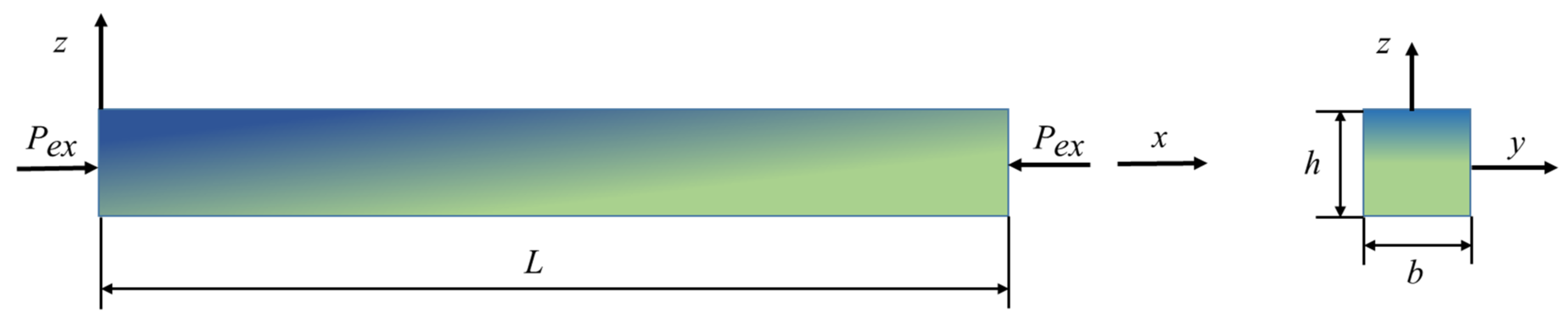
Figure 1 depicts a BDFG microbeam whose length, width and thickness are L, b and h, respectively. The BDFG microbeams are composed of two distinct materials with continuous characteristics that vary in x and z directions. The effective material properties P, including density ρ, Young’s modulus E and size effect parameter l, are expressed as [35]
in which the subscripts i (i = 1, 2) refer to the two components of BDFG, respectively.
Furthermore, and are defined as the following four different kinds of power-law distribution function [36,37]:
where m and n are gradient indexes governing material variation. Type I and II are symmetrical in the thickness direction, while Type III and IV are asymmetrical.
By the CCST, the displacement gradient tensor is divided into two parts: one is symmetric and the other is skew-symmetric [33].
where is the strain fields and is rotation fields. The subscripts “,i” or “,j” denote the differential to i or j.
The rotation vector dual to the rotation tensor is defined by
in which, is the Livi-Civita symbol.
The antisymmetric tensor is the curvature tensor, which is represented by
In the case of isotropic materials, the constitutive relations are taken as the following form [27]
in which λ is the Lame constant, is the Kronecker delta and G is the shear modulus. Moreover, is a CCST material constant and l is the material length-scale parameter.
Accordingly, the strain energy of isotropic elastomer is given as
By the Timoshenko beam theory, the displacement field takes the form of
where (i = 1, 2, 3) is the displacement along x, y and z directions, respectively. u and w denote the displacements of the midplane in x and z directions. ϕ represents the shear deformation of the microbeam.
The non-zero von Karman nonlinear strain, engineering shear strain and curvature tensor can be obtained by using Equations (6)–(9) and (13)
According to Equations (10) and (11), the related normal stress tensor, shear stress tensor and couple stress tensor are obtained as
in which .
Hamilton’s principle is used to formulate the governing equation, which reads
Using Equations (14)–(15), the variational form of strain energy is
in which the stress and couple-stress terms are expressed as follows
in which denotes the shear correction coefficient.
The rigidity terms are defined as
The variational form of kinetic energy is written as
where the inertia terms are defined as
The virtual work caused by the externally applied force could be expressed as
Substituting Equations (17), (20) and (22) into Equation (16), the nonlinear governing equations can be derived into the following form
The boundary conditions at both ends of the microbeam (x = 0, L) are given as:
.
In the present study, the dimensionless quantities are used:
Therefore, the dimensionless coefficients are given as
3. Solution Procedures
3.1. Methodology
Since the motion of microbeams is governed by a set of variable-coefficient partial differential equations, it is difficult to acquire the analytical solution of this system. The DQM [38] is suitable to solve this issue. Based on the DQM, the arbitrary r order differential of a function f(x) at can be calculated by
in which N denotes the number of discrete nodes and is the weighting coefficient of the r-th order differential.
The Chebyshev-Gauss-Lobatto points are used to discretize the nodes on the beam domain.
3.2. Free Vibration
Introducing Equations (25)–(28) into Equations (23) and (24), the non-dimensional governing equations are discretized as
where “” is the Hadamard product [39] and denote the unknown dynamic displacement vectors. The variable coefficients are also discretized. For example,
The discrete form of boundary conditions is as follows.
Clamped (C):
Simply supported (S):
where denotes the unit matrix, i = 1 or N represent the first or last row of a matrix.
Neglecting the external force and non-linear terms in Equation (29) and taking the dynamic displacement vector X as , the linear free vibration of a microbeam is sought as an eigenvalue problem
in which ω denotes the natural frequency of microbeams. K and M are the rigidity and mass matrix, respectively. Mode vector takes the form .
3.3. Buckling and Postbuckling
Dismissing the terms relating to time, the static buckling problem is reduced from Equation (29)
where are the static deformations. The associated boundary conditions are the same as the previous results, represented in Equations (30) and (31).
The critical buckling load and buckling paths of the BDFG microbeam can be achieved by using the pseudo-arc-length continuation technique or the Newton–Raphson iteration method. In this study, the obtained non-linear equations are dealt with using Newton’s method.
3.4. Postbuckling Vibration
Introducing a tiny disturbance near the buckled configuration, the vibration tendency of a BDFG microbeam in the vicinity of the post-buckling domain is studied. Thus, the total displacement field variables can be written as
in which denote the small disturbances near the buckled configurations.
Inserting Equation (34) into Equation (29), dismissing the non-linear terms, the postbuckling vibration problem in matrix form is given as
The boundary conditions are as follows.
Clamped (C):
Simply supported (S):
The obtained discretized equation Equation (35) is also an eigenvalue question, which can be solved by the methodology mentioned above.
4. Numerical Results
In this section, the free vibration, static buckling and post-buckling behaviors are investigated under different boundary conditions. If there is no special statement, the Type IV power-law distribution function is used in the numerical examples in addition to the aspect ratio L/h = 50 and b = h. Assuming a microbeam is composed of Ni () and Ti (). Using the available experimental data [40], the microstructure scale parameter in CCST could be obtained via fitting the data with the CCST. The calculated length-scale parameters of Ni and Ti are and , respectively. The material length-scale parameters of Ni and Ti corresponding to MCST [40] are 1.553 μm and 0.775 μm, respectively. The outcomes reveal that the microstructure parameter in CCST is roughly half that of the MCST.
4.1. Verification
To authenticate the developed model and solution method, three comparative studies were carried out. Firstly, Table 1 compares the first fundamental frequencies of TFG (m = 0) Timoshenko microbeam with those presented by Reddy [41]. In this example, the material parameters are taken as: l = h = 17.6 μm, b = 2h, L = 20h. Furthermore, supposing Poisson’s ratio is unvarying, its value is 0.38. The dimensionless frequency is defined as . Table 1 shows that the results obtained from this study are consistent with those reported by Reddy.
4.2. Characteristics of Free Vibration and Buckling
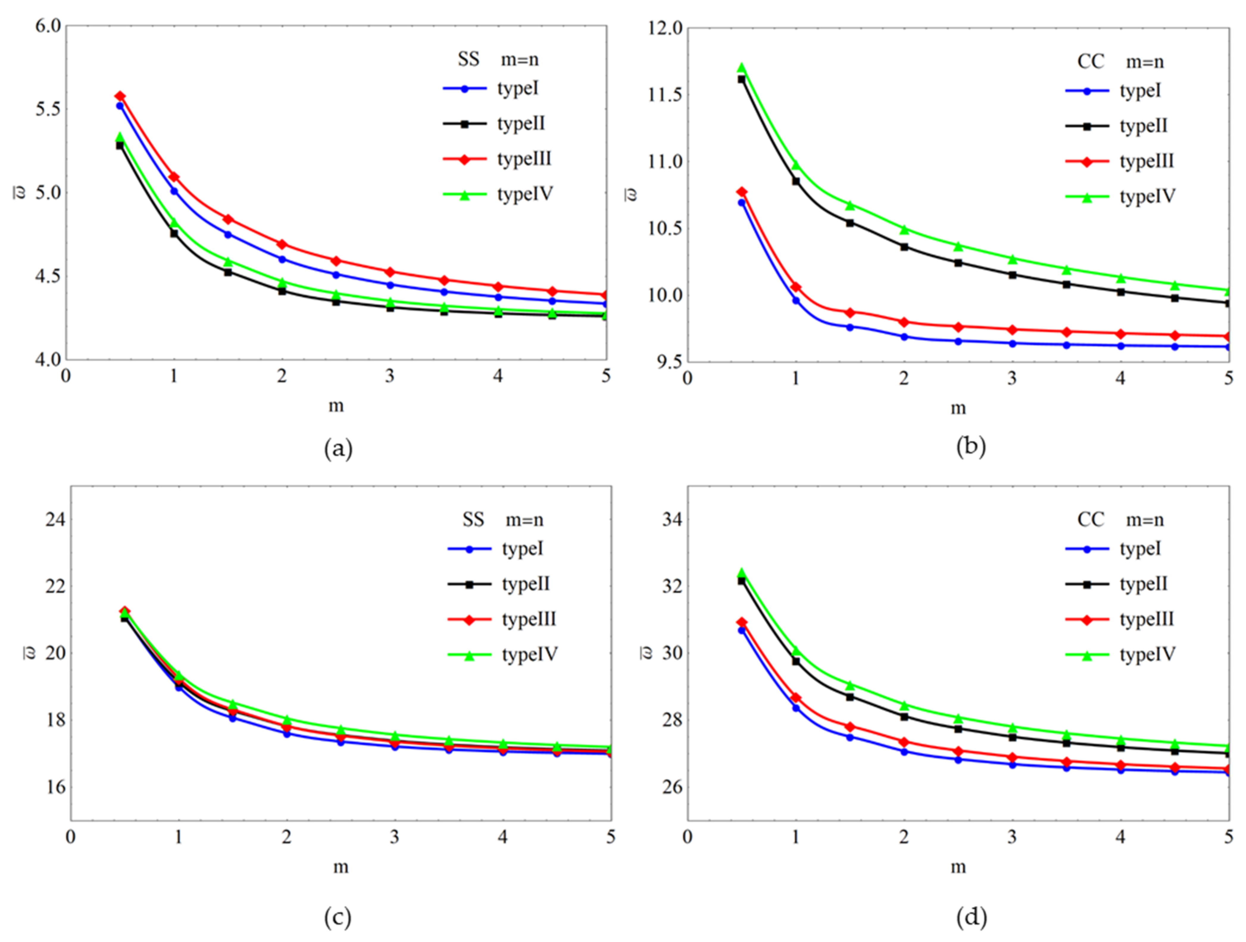
To illustrate the influence of different types of material distribution on non-dimensional frequencies, a BDFG microbeam has = 2 and L/h = 50. In Figure 3, the difference of the first two order nondimensional frequencies of microbeam with respect to m is depicted for distinct types of boundary condition. Figure 3 shows that as the functionally graded indices m and n become larger, the frequencies of four types of distribution decrease sharply and eventually converge. The descent is due to the fact that the larger the gradient parameters are, the weaker the rigidity of the BDFG microbeam. The same downward trend can be seen in Figure 3b for the CC microbeam, but the difference between the SS and CC microbeams is that the frequencies of the CC microbeam predicted by using Type II and IV are larger than those predicted by using Type I and III, while the results of the SS microbeam are close. Another observation is that the second frequencies predicted by different material distributions are closer. That is to say, the effect of material distribution on the increase in frequency becomes smaller.
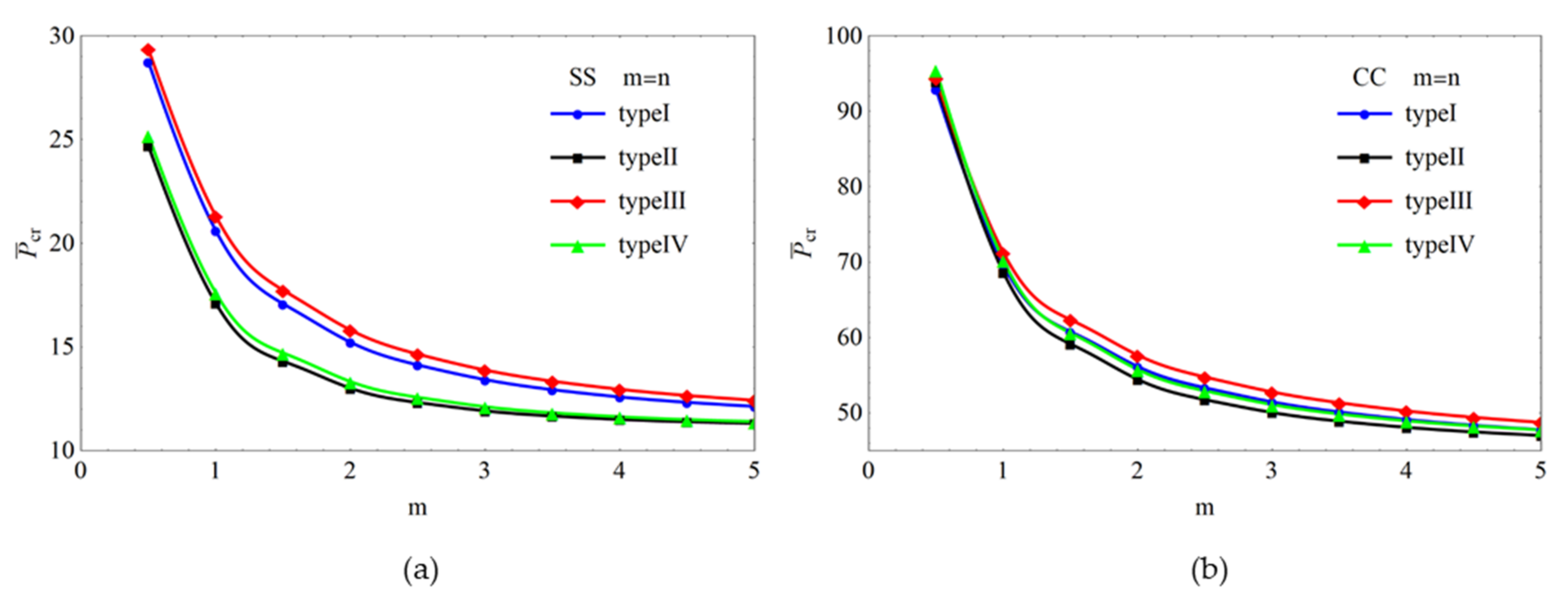
Figure 4 depicts the critical axial force of BDFG microbeams as the ascent of material indexes m and n by considering four types of material distribution. What observation in this figure is that the change of critical buckling loads about different distribution functions is similar to the previous vibration analysis. That is to say, with the growth of m and n, the stiffness of microbeam becomes smaller, resulting in a smaller critical buckling load. It should be pointed out that there is no significant difference among the results calculated by different types of distribution functions.
4.3. Post-Buckling Investigation of Microbeam
As shown in Figure 5a, the post-buckling behaviors of SS BDFG microbeams with various material distributions are different. The critical buckling loads predicted by Type I and Type III are significantly larger than Type II and Type IV. One can observe from Figure 5b that the post-buckling paths of the CC microbeam have nothing to do with the material distribution.
Figure 6 plots the buckling paths of the BDFG microbeam under different values of the nondimensional microstructure length-scale parameter . As shown in this image, as the value of increases, the critical buckling load decreases while the postbuckling amplitude increases. Another discovery is that under identical conditions, the CC boundary condition leads to larger critical buckling loads and post-buckling deflection.
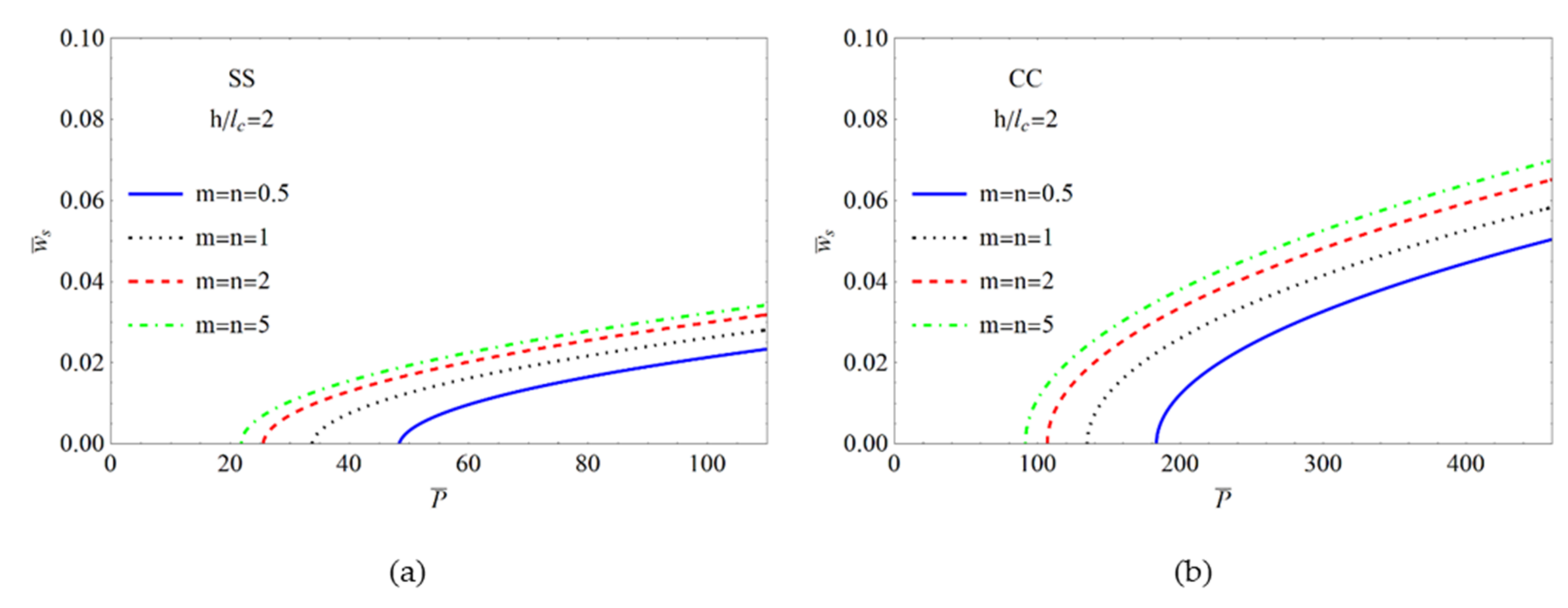
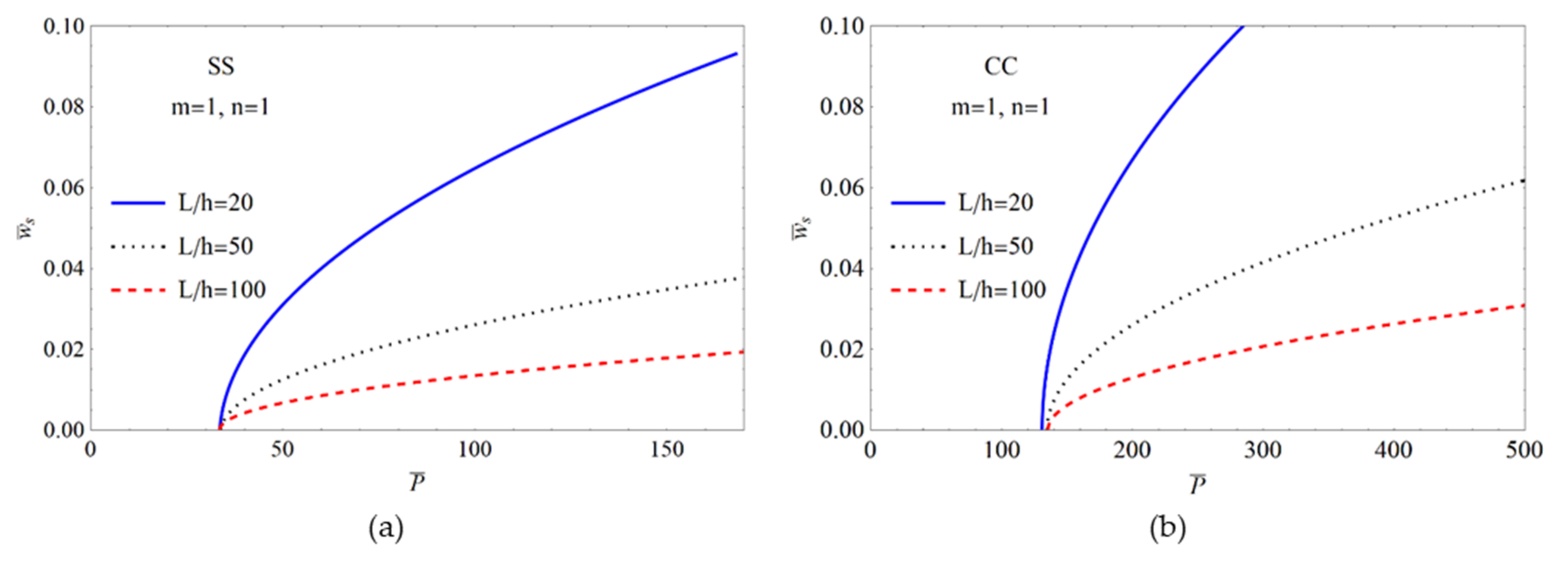
Figure 7 presents the impact of material gradient indexes on the buckling paths of the BDFG microbeams. The results were obtained based on the following parameters: L = 50h and = 2. The results reveal that when the indexes enlarge, the critical buckling load diminishes. That is because increasing the gradient indexes resulted in a reduction in the microbeam’s stiffness, which is also explicated in last section. The post-buckling response with varying aspect ratios is presented in Figure 8. One can observe that the aspect ratio makes a significant contribution to the post-buckling deflection and less of a contribution to the critical buckling load.
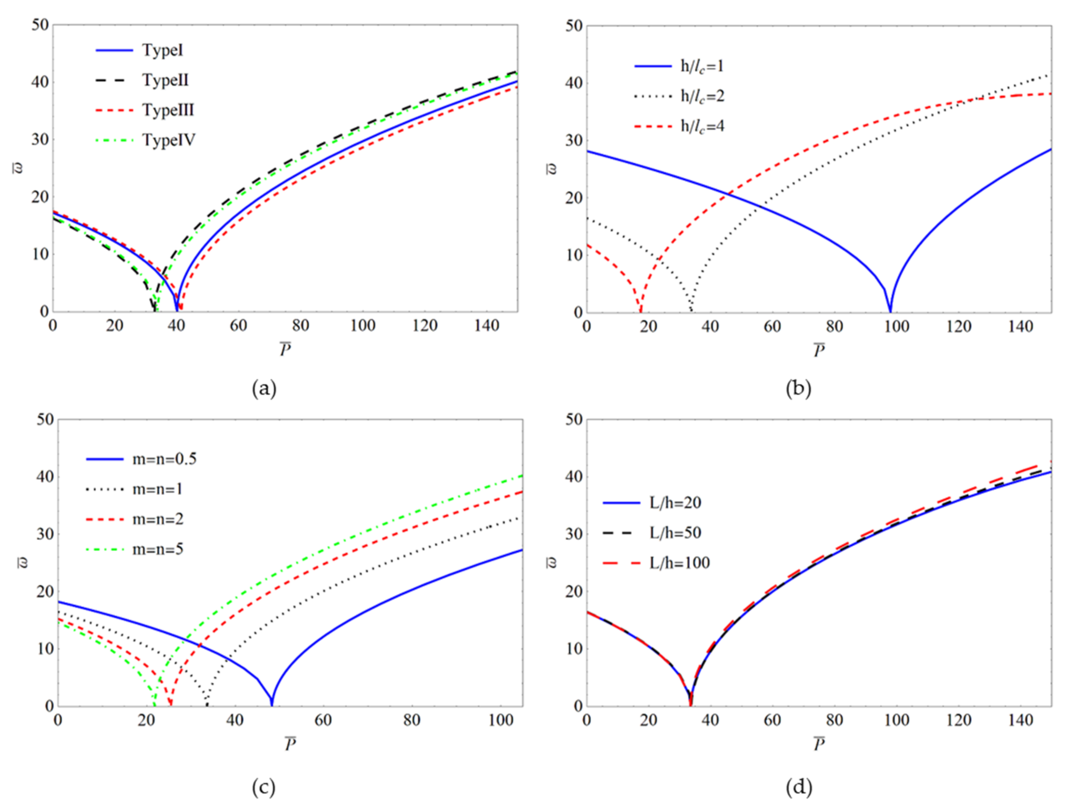
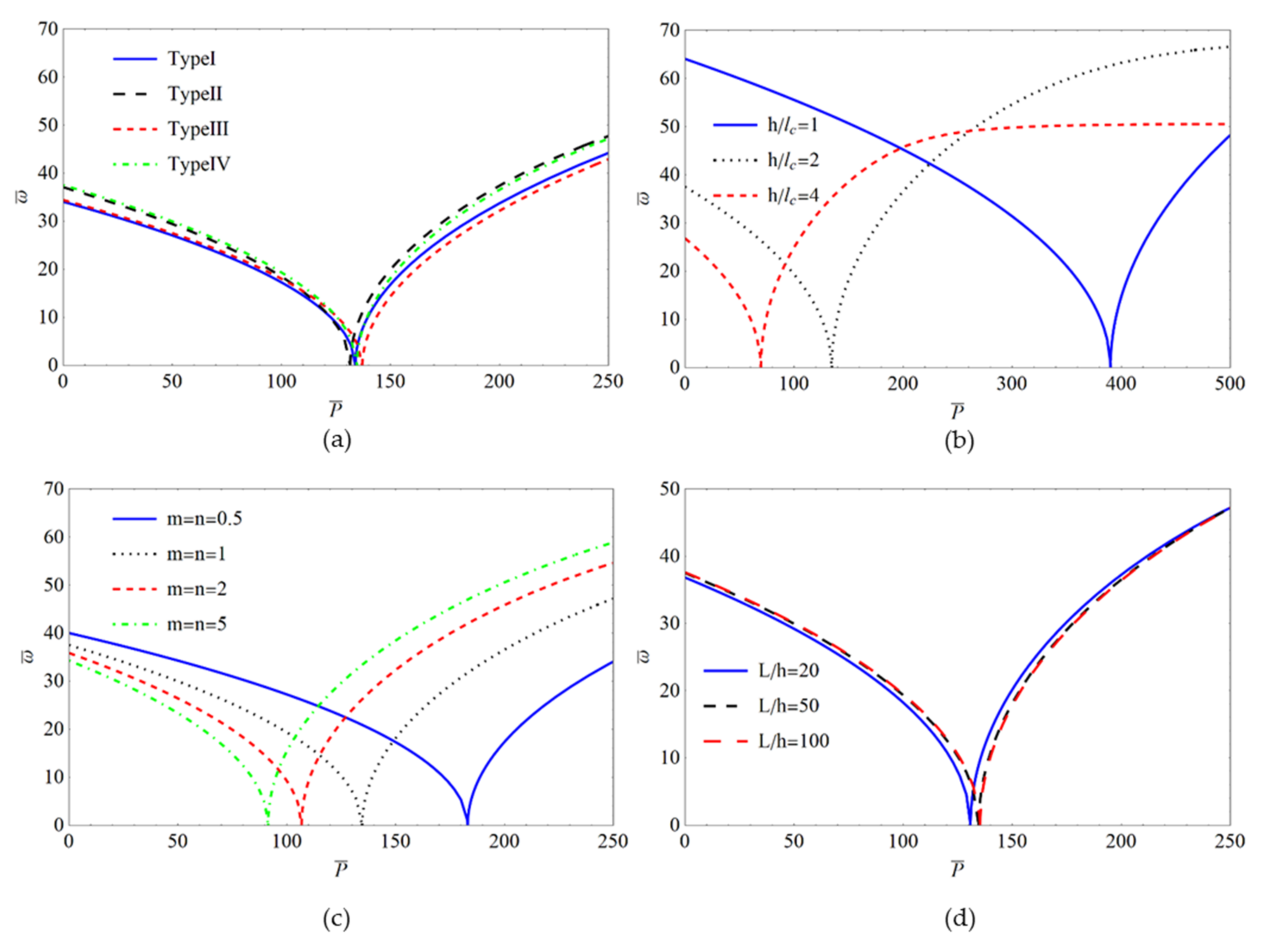
Figure 9 and Figure 10 illustrate the variation of the fundamental frequency in both the pre-buckling and post-buckling domains for the SS and CC BDFG microbeams. A common discovery is that the frequencies in the pre-buckling domain diminish with the increasing axial force until they reach zero. However, it is the opposite in the postbuckling range. Figure 9a and Figure 10a illustrate that the material distribution type has a greater influence on the first frequency of the SS microbeam compared to the CC microbeam. Figure 9b and Figure 10b show the intercorrelations among frequency responses in the pre-and post-buckling domains. The images reveal that the non-dimensional length-scale parameter affects the results significantly. As the thickness of the microbeam approaches the material length-scale parameter gradually, the predicted critical buckling load increases, which means the developed model can capture the size effect effectively. Figure 9c and Figure 10c reveal that the BDFG microbeam with the smallest material gradient index produces the largest critical buckling load. Considering BDFG microbeams with different length-to-thickness ratios, the frequency responses are depicted in Figure 9d and Figure 10d. When the aspect ratio varies, nearly the same vibration characteristics are observed.
5. Conclusions
In this study, the authors investigate the vibration, buckling, and post-buckling behaviors of BDFG microbeam. The mathematical formulation was obtained by using the Timoshenko beam theory and CCST. Utilizing Hamilton’s principle, the governing equations were obtained. DQM and iterative Newton’s method were employed to solve the obtained equations. Th numerical results demonstrated the influence of the symmetrical and asymmetrical material distribution, size effect, gradient parameters and aspect ratio on the first two order frequencies, critical buckling load and post-buckling characteristics of the BDFG microbeam under different boundary conditions. Some of the conclusions of the article are as follows:
- 1.
- The small scale parameter in CCST equals roughly half of the MCST.
- 2.
- Increasing the gradient indexes, the frequencies and critical buckling load diminish. The frequencies and critical axial force do not change when the gradient indexes are considerable.
- 3.
- The influence of the material distribution type on the first frequencies is significantly greater than that of the second frequencies. In addition, the first-order frequencies of the CC microbeams with different material distribution types are quite different. Furthermore, the critical buckling loads are close among these four types of distribution.
- 4.
- The aspect ratio influences the buckling path significantly, but makes nearly no contribution to the critical buckling load.
- 5.
- With declining , the predicted critical buckling loads increase significantly for all boundary conditions and the size effect becomes more pronounced.
Author Contributions
Conceptualization and methodology, R.Z., H.B. and X.C.; data curation, R.Z.; validation, R.Z., H.B., and X.C.; writing—original draft preparation, R.Z.; writing—review and editing, X.C., and H.B; funding acquisition, X.C. All authors have read and agreed to the published version of the manuscript.
Funding
This research was funded by National Natural Science Foundation of China (Grant Nos. 12002088, 12002225, 12072301), Natural Science Foundation of Fujian Province (Grant Nos. 2020J05103, 2020J05102, 2020J05101), Education and Scientific Research Foundation for Young Teachers in Fujian Province (Grant No. JAT190008) and Starting Grants of Fuzhou University (Grant No. GXRC-20017).
Institutional Review Board Statement
Not applicable.
Informed Consent Statement
Not applicable.
Data Availability Statement
The data presented in this study are available from the corresponding author upon reasonable request.
Conflicts of Interest
The authors declare no conflict of interest.
References
- Coffel, J.; Nuxoll, E. BioMEMS for biosensors and closed-loop drug delivery. Int. J. Pharm. 2018, 544, 335–349. [Google Scholar] [CrossRef] [PubMed]
- Tahmasebipour, M.; Vafaie, A. A novel single axis capacitive MEMS accelerometer with double-sided suspension beams fabricated using μ WEDM. Sens. Actuators A Phys. 2020, 309, 112003. [Google Scholar] [CrossRef]
- Lyu, M.; Zhao, J.; Kacem, N.; Liu, P.; Tang, B.; Xiong, Z.; Wang, H.; Huang, Y. Exploiting nonlinearity to enhance the sensitivity of mode-localized mass sensor based on electrostatically coupled MEMS resonators. Int. J. Nonlin. Mech. 2020, 121, 103455. [Google Scholar] [CrossRef]
- Lam, D.C.C.; Yang, F.; Chong, A.C.M.; Wang, J.; Tong, P. Experiments and theory in strain gradient elasticity. J. Mech. Phys. Solids 2003, 51, 1477–1508. [Google Scholar] [CrossRef]
- Jin, J.; Hu, N.; Hu, H. Investigation of size effect on band structure of 2D nano-scale phononic crystal based on nonlocal strain gradient theory. Int. J. Mech. Sci. 2022, 219, 107100. [Google Scholar] [CrossRef]
- Dinachandra, M.; Alankar, A. Static and dynamic modeling of functionally graded Euler-Bernoulli microbeams based on reformulated strain gradient elasticity theory using isogeometric analysis. Compos. Struct. 2022, 280, 114923. [Google Scholar] [CrossRef]
- Roostai, H.; Haghpanahi, M. Vibration of nanobeams of different boundary conditions with multiple cracks based on nonlocal elasticity theory. Appl. Math. Model. 2014, 38, 1159–1169. [Google Scholar] [CrossRef]
- Yang, F.; Chong, A.C.M.; Lam, D.C.C.; Tong, P. Couple stress based strain gradient theory for elasticity. Int. J. Solids Struct. 2002, 39, 2731–2743. [Google Scholar] [CrossRef]
- Chen, X.; Li, Y. Size-dependent post-buckling behaviors of geometrically imperfect microbeams. Mech. Res. Commun. 2018, 88, 25–33. [Google Scholar] [CrossRef]
- Saleh, B.; Jiang, J.; Fathi, R.; Al-hababi, T.; Xu, Q.; Wang, L.; Song, D.; Ma, A. 30 Years of functionally graded materials: An overview of manufacturing methods, Applications and Future Challenges. Compos. Part B Eng. 2020, 201, 108376. [Google Scholar] [CrossRef]
- Chandrasekaran, S.; Hari, S.; Amirthalingam, M. Functionally graded materials for marine risers by additive manufacturing for high-temperature applications: Experimental investigations. Structures 2022, 35, 931–938. [Google Scholar] [CrossRef]
- Luginina, M.; Angioni, D.; Montinaro, S.; Orrù, R.; Cao, G.; Sergi, R.; Bellucci, D.; Cannillo, V. Hydroxyapatite/bioactive glass functionally graded materials (FGM) for bone tissue engineering. J. Eur. Ceram. Soc. 2020, 40, 4623–4634. [Google Scholar] [CrossRef]
- Boggarapu, V.; Gujjala, R.; Ojha, S.; Acharya, S.; Venkateswara Babu, P.; Chowdary, S.; Kumar Gara, D. State of the art in functionally graded materials. Compos. Struct. 2021, 262, 113596. [Google Scholar] [CrossRef]
- Şimşek, M.; Reddy, J.N. Bending and vibration of functionally graded microbeams using a new higher order beam theory and the modified couple stress theory. Int. J. Eng. Sci. 2013, 64, 37–53. [Google Scholar] [CrossRef]
- Akgöz, B.; Civalek, Ö. Free vibration analysis of axially functionally graded tapered Bernoulli-Euler microbeams based on the modified couple stress theory. Compos. Struct. 2013, 98, 314–322. [Google Scholar] [CrossRef]
- Nateghi, A.; Salamat-talab, M.; Rezapour, J.; Daneshian, B. Size dependent buckling analysis of functionally graded micro beams based on modified couple stress theory. Appl. Math. Model. 2012, 36, 4971–4987. [Google Scholar] [CrossRef]
- Li, X.; Li, L.; Hu, Y.; Ding, Z.; Deng, W. Bending, buckling and vibration of axially functionally graded beams based on nonlocal strain gradient theory. Compos. Struct. 2017, 165, 250–265. [Google Scholar] [CrossRef]
- Akbarzadeh Khorshidi, M.; Shariati, M.; Emam, S.A. Postbuckling of functionally graded nanobeams based on modified couple stress theory under general beam theory. Int. J. Mech. Sci. 2016, 110, 160–169. [Google Scholar] [CrossRef]
- Chen, X.; Lu, Y.; Li, Y. Free vibration, buckling and dynamic stability of bi-directional FG microbeam with a variable length scale parameter embedded in elastic medium. Appl. Math. Model. 2019, 67, 430–448. [Google Scholar] [CrossRef]
- Bhattacharya, S.; Das, D. Free vibration analysis of bidirectional-functionally graded and double-tapered rotating micro-beam in thermal environment using modified couple stress theory. Compos. Struct. 2019, 215, 471–492. [Google Scholar] [CrossRef]
- Chen, X.; Zhang, X.; Lu, Y.; Li, Y. Static and dynamic analysis of the postbuckling of bi-directional functionally graded material microbeams. Int. J. Mech. Sci. 2019, 151, 424–443. [Google Scholar] [CrossRef]
- Yang, T.; Tang, Y.; Li, Q.; Yang, X. Nonlinear bending, buckling and vibration of bi-directional functionally graded nanobeams. Compos. Struct. 2018, 204, 313–319. [Google Scholar] [CrossRef]
- Lei, J.; He, Y.; Li, Z.; Guo, S.; Liu, D. Postbuckling analysis of bi-directional functionally graded imperfect beams based on a novel third-order shear deformation theory. Compos. Struct. 2019, 209, 811–829. [Google Scholar] [CrossRef]
- Nejad, M.Z.; Hadi, A.; Rastgoo, A. Buckling analysis of arbitrary two-directional functionally graded Euler–Bernoulli nano-beams based on nonlocal elasticity theory. Int. J. Eng. Sci. 2016, 103, 1–10. [Google Scholar] [CrossRef]
- Shafiei, N.; Kazemi, M. Buckling analysis on the bi-dimensional functionally graded porous tapered nano-/micro-scale beams. Aerosp. Sci. Technol. 2017, 66, 1–11. [Google Scholar] [CrossRef]
- Hadjesfandiari, A.R.; Dargush, G.F. Couple stress theory for solids. Int. J. Solids Struct. 2011, 48, 2496–2510. [Google Scholar] [CrossRef] [Green Version]
- Hadjesfandiari, A.R.; Dargush, G.F. Fundamental solutions for isotropic size-dependent couple stress elasticity. Int. J. Solids Struct. 2013, 50, 1253–1265. [Google Scholar] [CrossRef] [Green Version]
- Vaghefpour, H.; Arvin, H. Nonlinear free vibration analysis of pre-actuated isotropic piezoelectric cantilever Nano-beams. Microsyst. Technol. 2019, 25, 4097–4110. [Google Scholar] [CrossRef]
- Alashti, R.A.; Abolghasemi, A.H. A Size-dependent Bernoulli-Euler Beam Formulation based on a New Model of Couple Stress Theory. Int. J. Eng. 2014, 27, 951–960. [Google Scholar]
- Hadi, A.; Nejad, M.Z.; Rastgoo, A.; Hosseini, M. Buckling analysis of FGM Euler-Bernoulli nano-beams with 3D-varying properties based on consistent couple-stress theory. Steel Compos. Struct. 2018, 26, 663–672. [Google Scholar] [CrossRef]
- Haghshenas Gorgani, H.; Mahdavi Adeli, M.; Hosseini, M. Pull-in behavior of functionally graded micro/nano-beams for MEMS and NEMS switches. Microsyst. Technol. 2019, 25, 3165–3173. [Google Scholar] [CrossRef]
- Seyyed Fakhrabadi, M.M. Size effects on nanomechanical behaviors of nanoelectronics devices based on consistent couple-stress theory. Int. J. Mech. Sci. 2015, 92, 146–153. [Google Scholar] [CrossRef]
- Alavi, S.E.; Sadighi, M.; Pazhooh, M.D.; Ganghoffer, J. Development of size-dependent consistent couple stress theory of Timoshenko beams. Appl. Math. Model. 2020, 79, 685–712. [Google Scholar] [CrossRef]
- Wu, C.; Hu, H. A unified size-dependent plate theory for static bending and free vibration analyses of micro- and nano-scale plates based on the consistent couple stress theory. Mech. Mater. 2021, 162, 104085. [Google Scholar] [CrossRef]
- Chen, X.; Lu, Y.; Zhu, B.; Zhang, X.; Li, Y. Nonlinear resonant behaviors of bi-directional functionally graded material microbeams: One-/two-parameter bifurcation analyses. Compos. Struct. 2019, 223, 110896. [Google Scholar] [CrossRef]
- Chen, X.; Huang, S.; Zhu, B.; Wu, R.; Ren, Z. A domain decomposition method based vibration analysis of BDFGs imperfect beams with arbitrary boundary conditions. Compos. Struct. 2022, 284, 115115. [Google Scholar] [CrossRef]
- Chen, X.; Chen, L.; Lu, Y. Imperfection sensitivity of nonlinear primary resonance behavior in bi-directional functionally graded porous material beam. Compos. Struct. 2021, 271, 114142. [Google Scholar] [CrossRef]
- Li, L.; Li, X.; Hu, Y. Nonlinear bending of a two-dimensionally functionally graded beam. Compos. Struct. 2018, 184, 1049–1061. [Google Scholar] [CrossRef]
- Attia, M.A.; Mohamed, S.A. Nonlinear thermal buckling and postbuckling analysis of bidirectional functionally graded tapered microbeams based on Reddy beam theory. Eng. Comput.-Ger. 2022, 38, 525–554. [Google Scholar] [CrossRef]
- Li, Z.; He, Y.; Lei, J.; Guo, S.; Liu, D.; Wang, L. A standard experimental method for determining the material length scale based on modified couple stress theory. Int. J. Mech. Sci. 2018, 141, 198–205. [Google Scholar] [CrossRef]
- Reddy, J.N. Microstructure-dependent couple stress theories of functionally graded beams. J. Mech. Phys. Solids 2011, 59, 2382–2399. [Google Scholar] [CrossRef]
- Şimşek, M. Buckling of Timoshenko beams composed of two-dimensional functionally graded material (2D-FGM) having different boundary conditions. Compos. Struct. 2016, 149, 304–314. [Google Scholar] [CrossRef]
- Yang, J.; Wu, H.; Kitipornchai, S. Buckling and postbuckling of functionally graded multilayer graphene platelet-reinforced composite beams. Compos. Struct. 2017, 161, 111–118. [Google Scholar] [CrossRef] [Green Version]
Figure 1.
Sketch of BDFG microbeam.

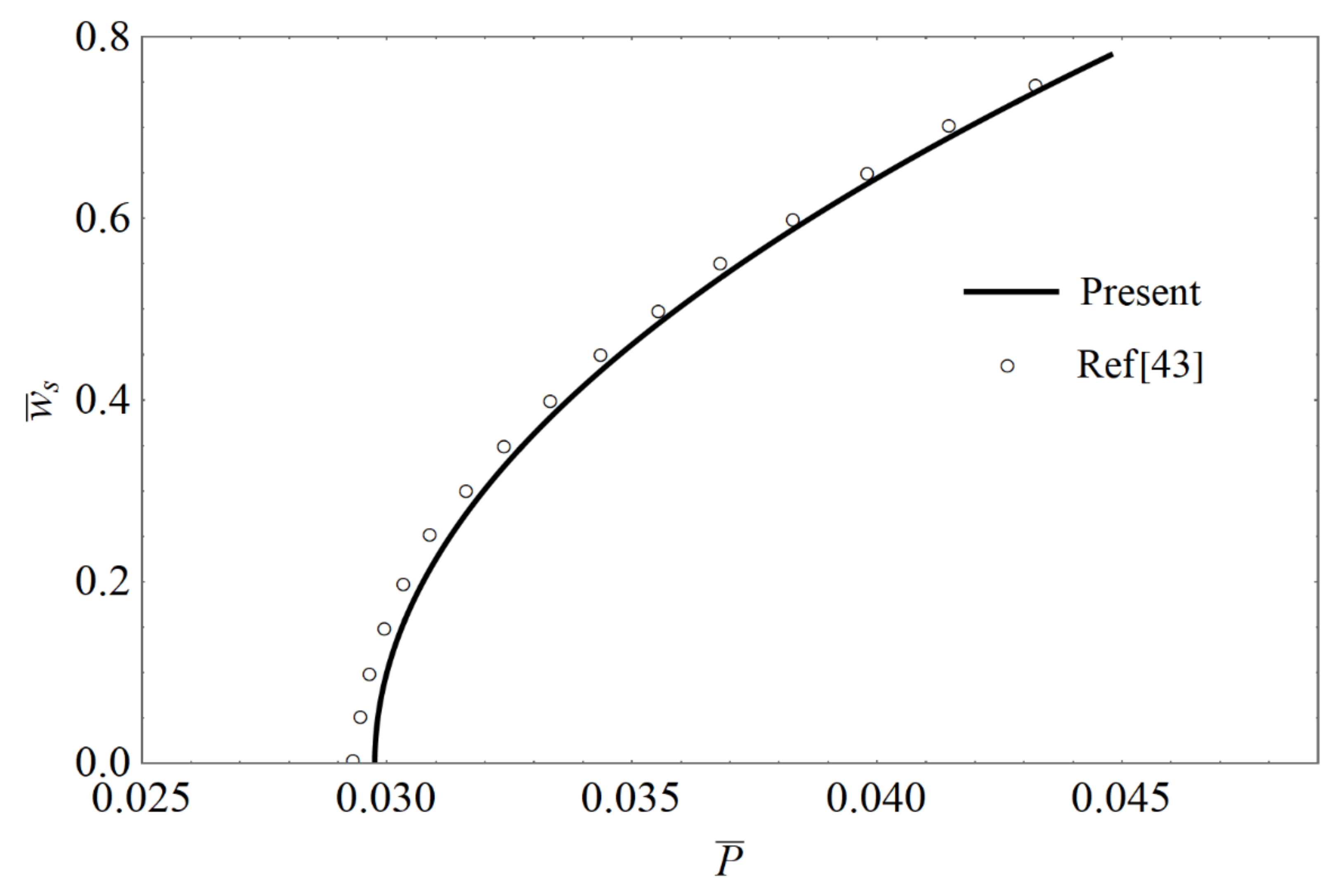
Figure 2.
Verification of the post-buckling path of CC homogenous beam when L = 10h.

Figure 3.
Influence of material distribution functions on the first-two nondimensional frequency: (a) The first dimensionless frequency for SS microbeam; (b) The first dimensionless frequency for CC microbeam; (c) The second dimensionless frequency for SS microbeam; (d) The second dimensionless frequency for CC microbeam.

Figure 4.
Variation of critical buckling loads for BDFG microbeam under different material distribution: (a) SS microbeam; (b) CC microbeam.
Figure 4.
Variation of critical buckling loads for BDFG microbeam under different material distribution: (a) SS microbeam; (b) CC microbeam.

Figure 5.
Effect of material distribution functions on postbuckling equilibrium paths: (a) SS microbeam; (b) CC microbeam.
Figure 5.
Effect of material distribution functions on postbuckling equilibrium paths: (a) SS microbeam; (b) CC microbeam.

Figure 6.
Variation of post-buckling equilibrium paths with different non-dimensional length scale parameter h/: (a) SS microbeam; (b) CC microbeam.
Figure 6.
Variation of post-buckling equilibrium paths with different non-dimensional length scale parameter h/: (a) SS microbeam; (b) CC microbeam.

Figure 7.
Influence of material gradient indexes on postbuckling equilibrium paths: (a) SS microbeam; (b) CC microbeam.
Figure 7.
Influence of material gradient indexes on postbuckling equilibrium paths: (a) SS microbeam; (b) CC microbeam.

Figure 8.
Influence of aspect ratio on postbuckling equilibrium paths: (a) SS microbeam; (b) CC microbeam.
Figure 8.
Influence of aspect ratio on postbuckling equilibrium paths: (a) SS microbeam; (b) CC microbeam.

Figure 9.
Fundamental frequency–axial load paths for SS BDFG microbeam: (a) Various material distributions; (b) various nondimensional length scale parameters; (c) various material gradient indexes; (d) various aspect ratios.
Figure 9.
Fundamental frequency–axial load paths for SS BDFG microbeam: (a) Various material distributions; (b) various nondimensional length scale parameters; (c) various material gradient indexes; (d) various aspect ratios.

Figure 10.
Fundamental frequency–axial load paths for CC BDFG microbeam: (a) Various material distribution; (b) various nondimensional length scale parameter; (c) various material gradient indexes; (d) various aspect ratio.
Figure 10.
Fundamental frequency–axial load paths for CC BDFG microbeam: (a) Various material distribution; (b) various nondimensional length scale parameter; (c) various material gradient indexes; (d) various aspect ratio.


Table 1.
Validation of the natural frequency of SS microbeam.
| l/h | n = 0 | n = 1 | n = 10 | |||
|---|---|---|---|---|---|---|
| Reddy [41] | Present | Reddy [41] | Present | Reddy [41] | Present | |
| 0 | 9.83 | 9.8262 | 8.67 | 8.6693 | 10.28 | 10.2890 |
| 0.2 | 10.65 | 10.6462 | 9.59 | 9.5904 | 11.07 | 11.0742 |
| 0.4 | 12.80 | 12.7924 | 11.93 | 11.9322 | 13.14 | 13.1491 |
| 0.8 | 19.08 | 19.0784 | 18.52 | 18.5231 | 19.30 | 19.3150 |
| 1.0 | 22.66 | 22.6567 | 22.28 | 22.1976 | 22.92 | 22.8536 |
Table 2.
Validation of the nondimensional critical buckling loads of BDFG microbeam with L/h = 50.
| SS | CC | ||||||
|---|---|---|---|---|---|---|---|
| n = 0.5 | n = 1 | n = 2 | n = 0.5 | n = 1 | n = 2 | ||
| m = 0.5 | Simsek [42] | 13.9210 | 12.9437 | 12.2448 | 54.3014 | 50.7252 | 48.1480 |
| Present | 13.9220 | 12.9450 | 12.2455 | 54.3289 | 50.7457 | 48.1584 | |
| m = 1 | Simsek [42] | 12.7328 | 12.0758 | 11.5957 | 50.4323 | 47.8749 | 46.0010 |
| Present | 12.7333 | 12.0765 | 11.5960 | 50.4497 | 47.8875 | 46.0063 | |
| m = 2 | Simsek [42] | 11.4355 | 11.0985 | 10.8445 | 46.7474 | 45.1060 | 43.8808 |
| Present | 11.4357 | 11.0988 | 10.8446 | 46.7525 | 45.1089 | 43.8796 |
Publisher’s Note: MDPI stays neutral with regard to jurisdictional claims in published maps and institutional affiliations. |
© 2022 by the authors. Licensee MDPI, Basel, Switzerland. This article is an open access article distributed under the terms and conditions of the Creative Commons Attribution (CC BY) license (https://creativecommons.org/licenses/by/4.0/).
Share and Cite
MDPI and ACS Style
Zhang, R.; Bai, H.; Chen, X. The Consistent Couple Stress Theory-Based Vibration and Post-Buckling Analysis of Bi-directional Functionally Graded Microbeam. Symmetry 2022, 14, 602. https://doi.org/10.3390/sym14030602
AMA Style
Zhang R, Bai H, Chen X. The Consistent Couple Stress Theory-Based Vibration and Post-Buckling Analysis of Bi-directional Functionally Graded Microbeam. Symmetry. 2022; 14(3):602. https://doi.org/10.3390/sym14030602
Chicago/Turabian StyleZhang, Rong, Hongbai Bai, and Xiaochao Chen. 2022. "The Consistent Couple Stress Theory-Based Vibration and Post-Buckling Analysis of Bi-directional Functionally Graded Microbeam" Symmetry 14, no. 3: 602. https://doi.org/10.3390/sym14030602
Note that from the first issue of 2016, this journal uses article numbers instead of page numbers. See further details here.