
Position-Aware Guided Hiding Data Scheme with Reversibility and Adaptivity for Dual Images


Abstract
:1. Introduction
2. Related Works
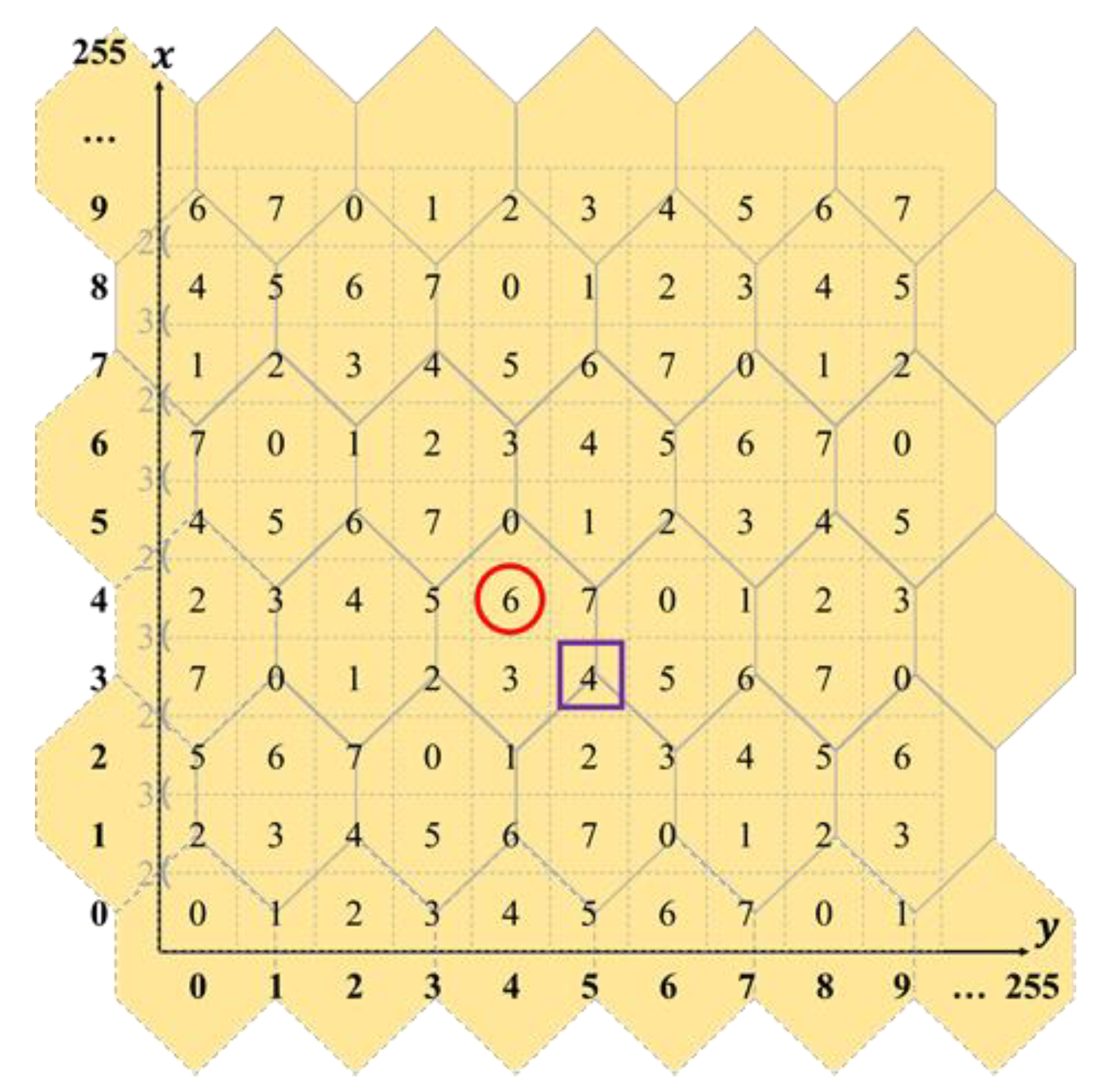
2.1. Turtle Shell-Based Reference Matrix
2.2. Review of Chen and Guo’s Scheme
3. Proposed Scheme
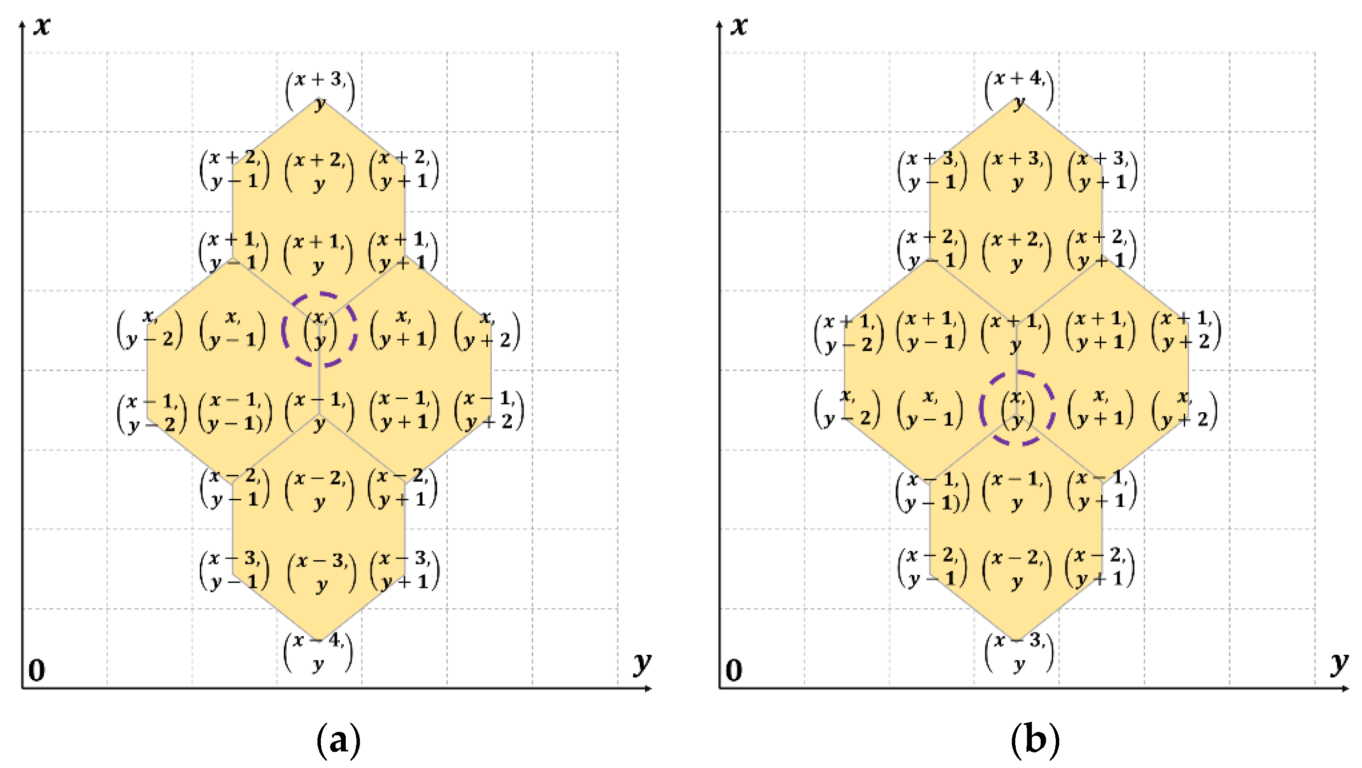
3.1. Position Combinations in a Sunflower Area
| Algorithm 1: Generation of effective position combinations for | |||
| Input:, R Output: Effective position combinations EPC | |||
| 1 | EPC = ∅ | ||
| 2 | If belongs to UBE/LBE: | ||
| 3 | Traverse each element in the sunflower area that corresponds to . | ||
| 4 | If is inside R and belongs to UBE/LBE: | ||
| 5 | Add the position combination into EPC. | ||
| 6 | Else, if is inside R and belongs to UEE/LEE: | ||
| 7 | Add the position combinations and into EPC. | ||
| 8 | End if | ||
| 9 | Else if belongs to UEE/LEE | ||
| 10 | Traverse each element in the sunflower area that corresponds to . | ||
| 11 | If is inside R and belongs to UEE/LEE | ||
| 12 | Add the position combination into EPC | ||
| 13 | End if | ||
| 14 | End if | ||
3.2. Shadow Construction
| Algorithm 2: Construction of the shadow images | ||
| Input:C, Msg, R Output:S1, S2 | ||
| 1 | Separate C into a set of non-overlapping pixel pairs in order from top to bottom, left to right, and denoted as , where and . | |
| 2 | Read an unvisited pixel pair from C and project it into the reference matrix R, i.e., . | |
| 3 | Identify ’s type into one of {UBE, LBE, UEE, LEE} according to Equation (1). | |
| 4 | Use Algorithm 1 to generate EPC for and then construct the corresponding ET. | |
| 5 | Convert Msg into a -ary numeral system to derive a -ary secret digit, . | |
| 6 | Use ET to embed into : | |
| 6.1 | Find the quaternion sequence in ET where . | |
| 6.2 | Modify two pixel pairs, i.e., in shadow S1 and in shadow S2. | |
| 7 | Repeat Steps 2 through 7 until all cover pixel pairs and secret message Msg have been dealt with. | |
| 8 | Output two shadow images, i.e., S1 and S2. | |
3.3. Extraction of Secret Messages and Recovery of the Cover Image
| Algorithm 3: Extracting secret messages, Msg, and restoring the cover image, C | |||
| Input: S1, S2, R Output: Msg, C | |||
| 1 | Separate shadow images S1 and S2 into a set of non-overlapping pixel pairs in order from top to bottom and from left to right, respectively. To ease the discussion, denote S1 as and S2 as , where and . | ||
| 2 | Read a couple of pixel pairs and and restore the original cover pixel pair as shown below: | ||
| 2.1 | Project and into R, i.e., and . | ||
| 2.2 | If belongs to UBE/LBE, set . | ||
| 2.3 | If belongs to UEE/LEE, then: | ||
| 2.3.1 | If belongs to UBE/LBE, set ; | ||
| 2.3.2 | Else set . | ||
| 3 | Project into R, i.e., . | ||
| 4 | Identify the type of as one of {UBE, LBE, UEE, LEE} according to Equation (1). | ||
| 5 | Use Algorithm 1 to generate EPC for and construct the corresponding ET. | ||
| 6 | Use ET to extract a secret digit, from and : | ||
| 6.1 | Find the quaternion sequence in ET to meet and . | ||
| 6.2 | Extract . | ||
| 7 | Convert in a -ary inverse numeral system to derive the sequence of the binary codes and concatenate it into Msg. | ||
| 8 | Repeat Steps 2 through 8 until all pixel pairs have been processed. | ||
| 9 | Output Msg and restore cover image C. | ||
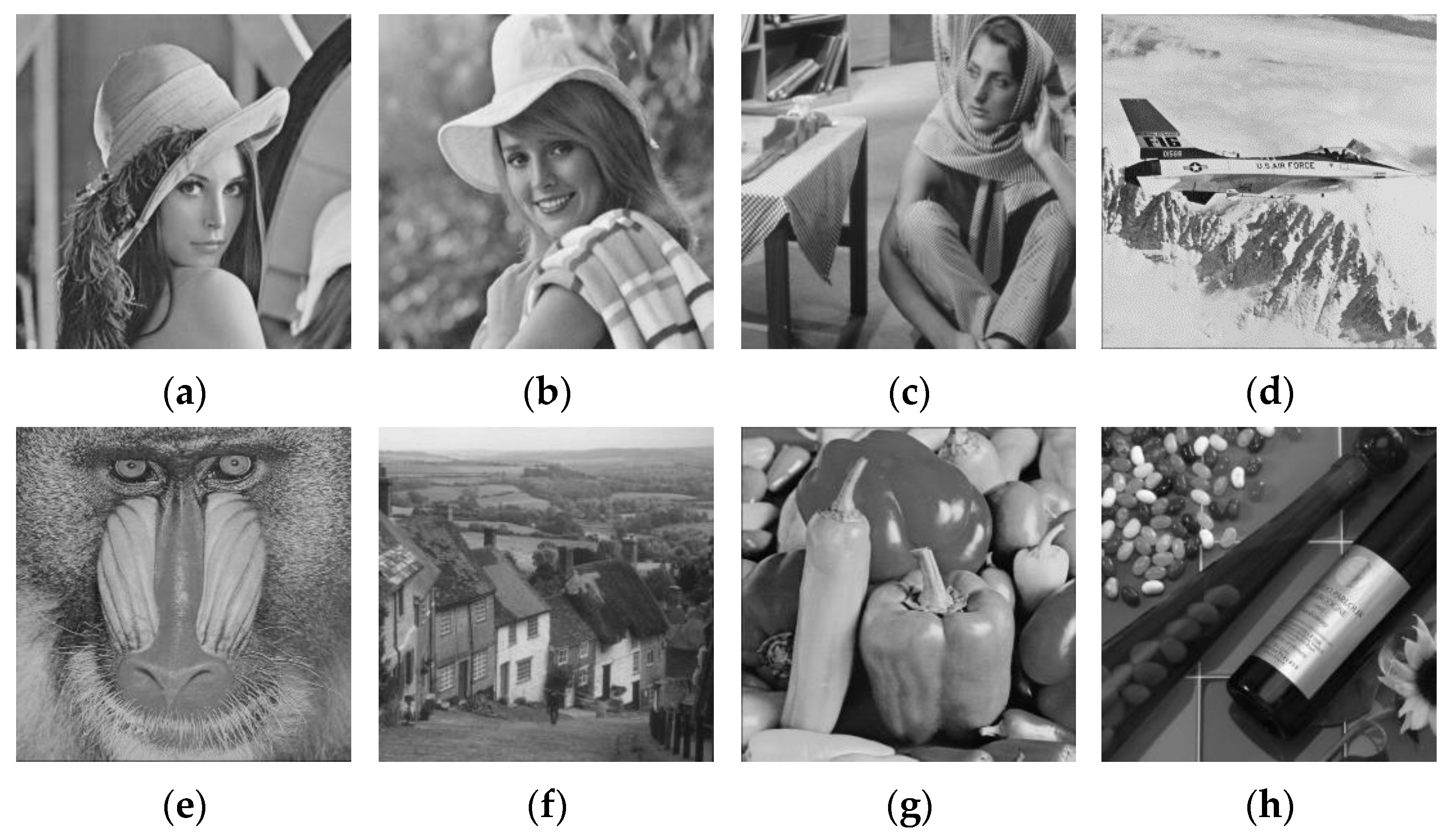
4. Experiments
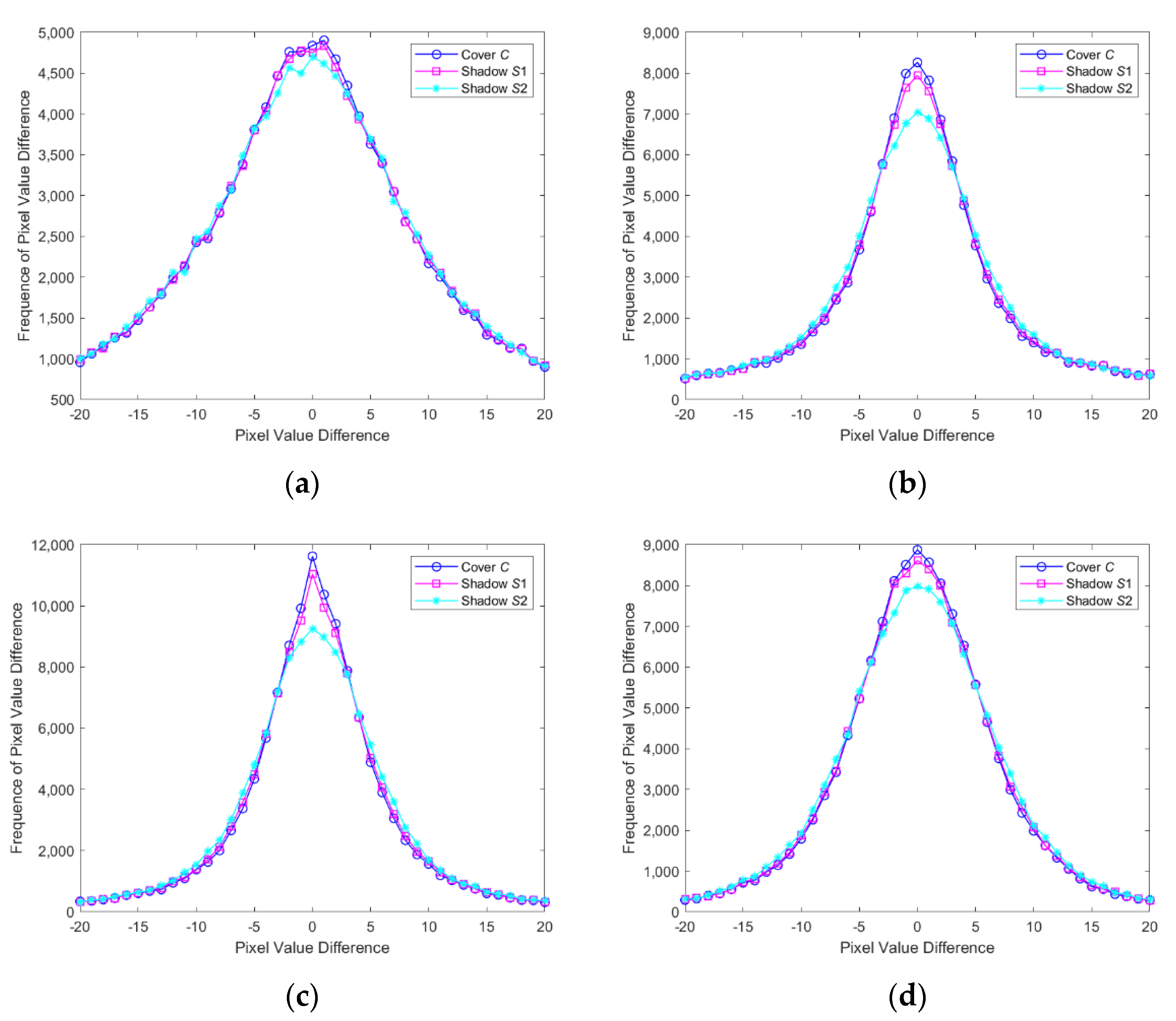
4.1. Security Analysis
4.1.1. PVD Histogram
4.1.2. Relative Entropy Analysis
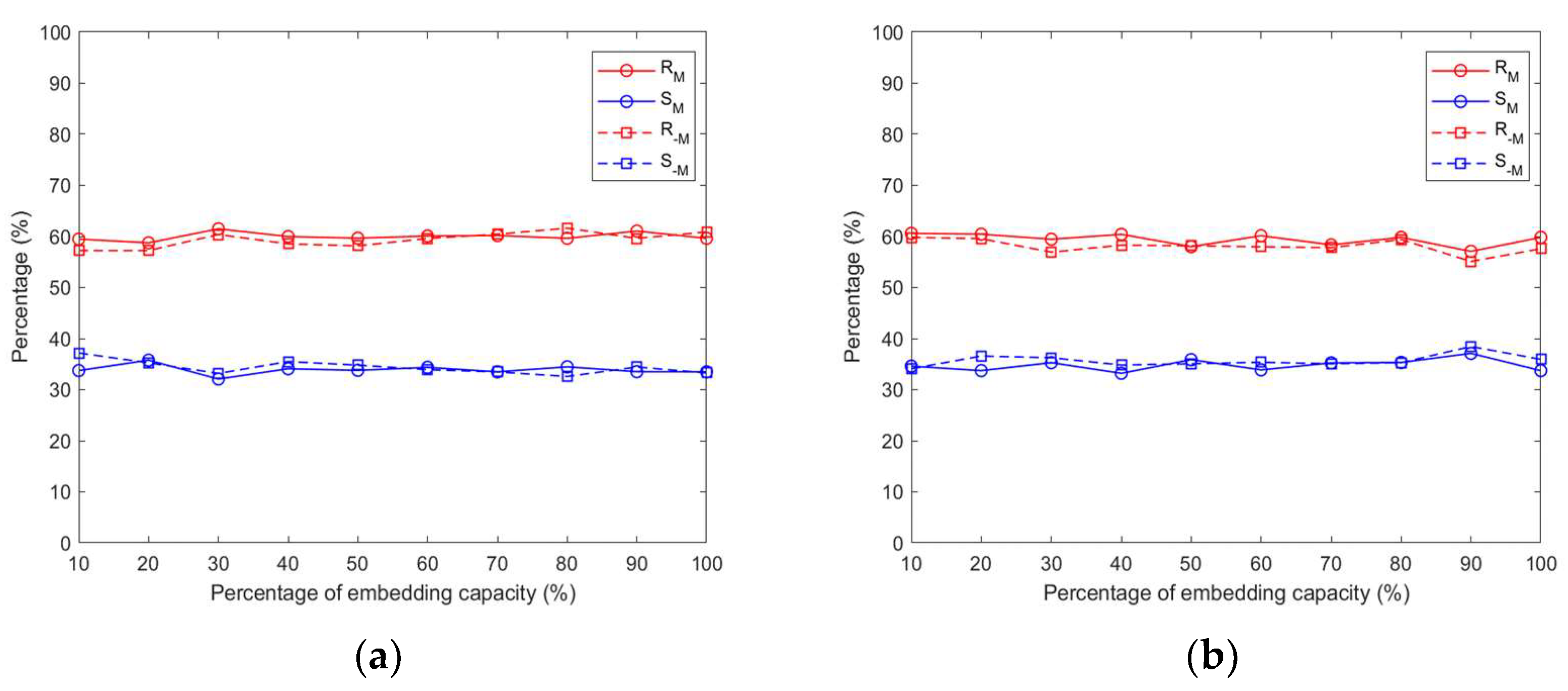
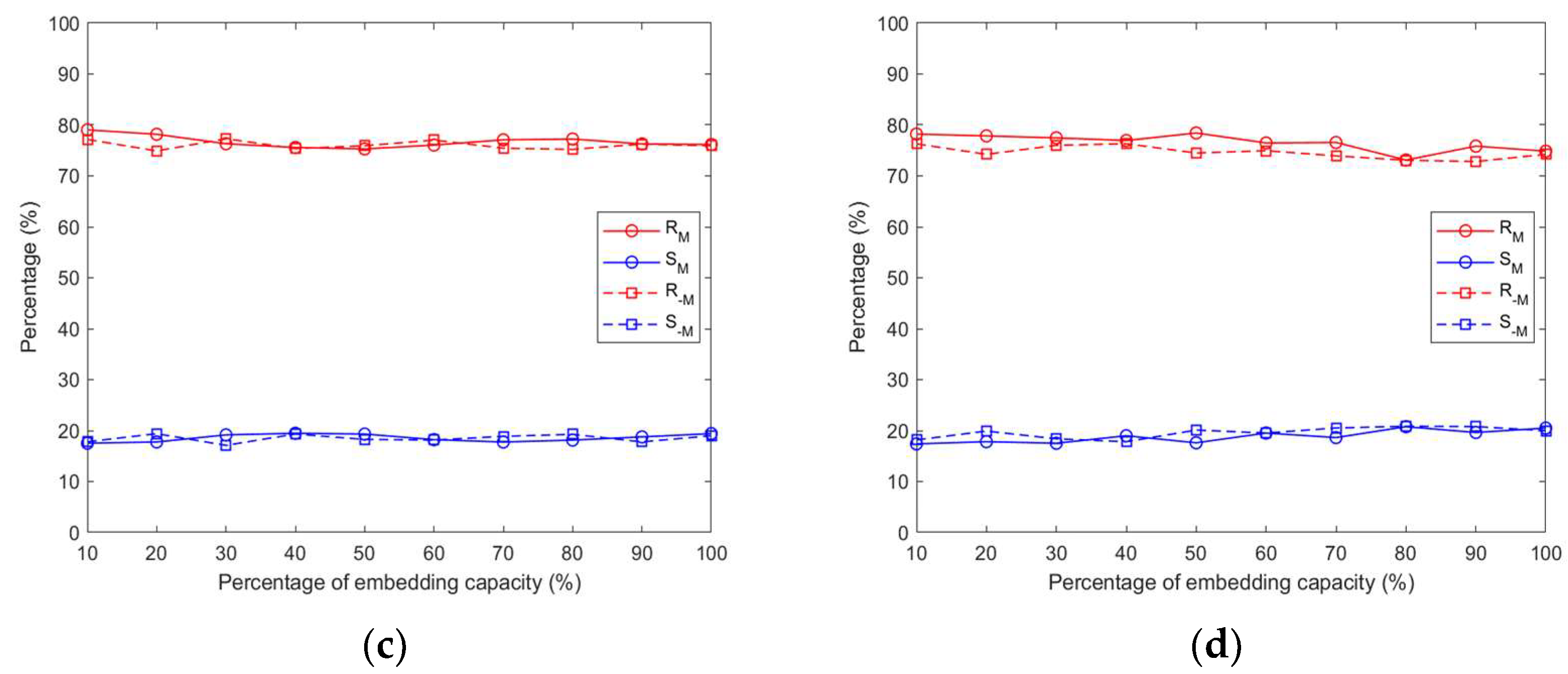
4.1.3. RS Steganalysis
4.2. Results of the Proposed Scheme
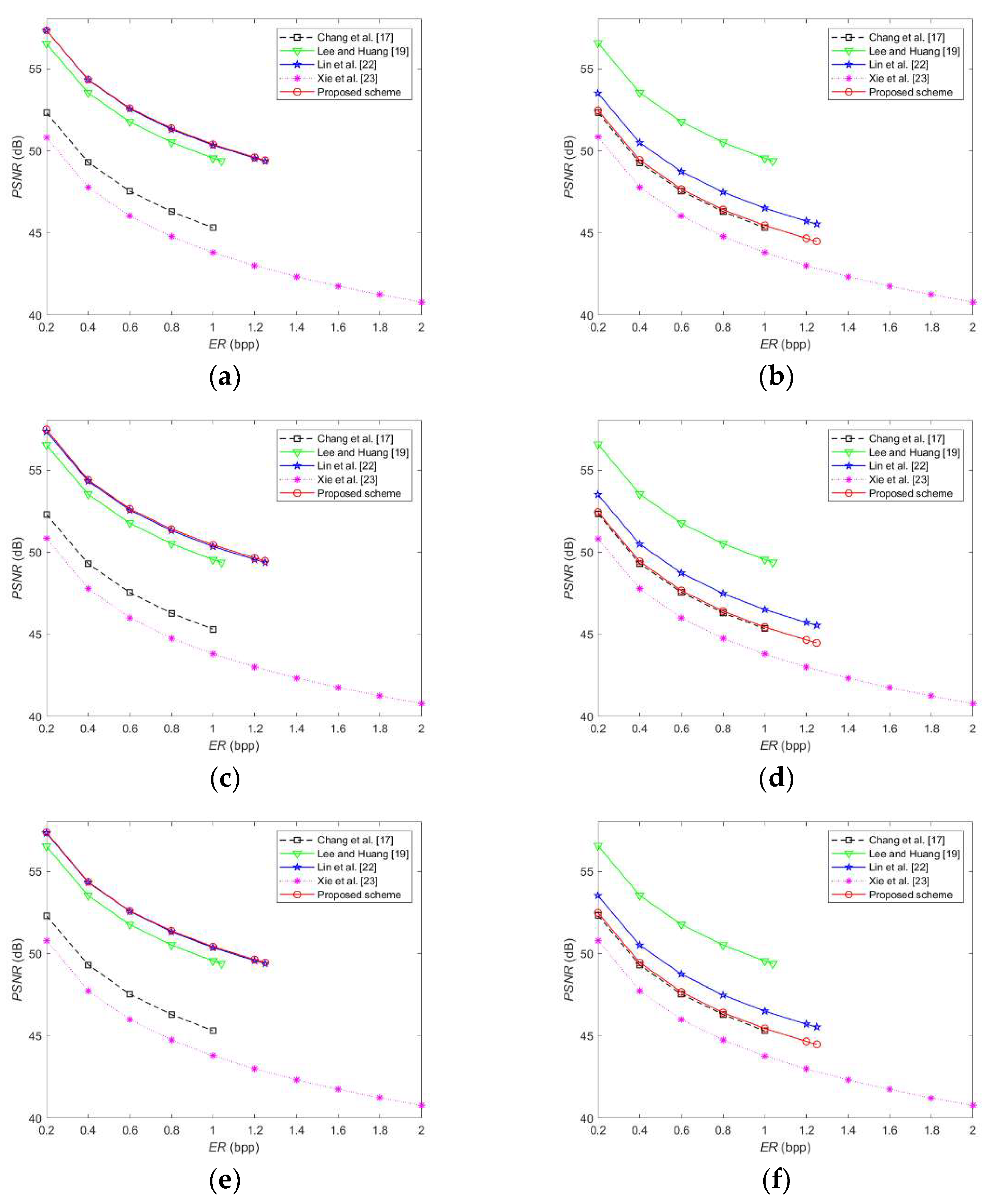
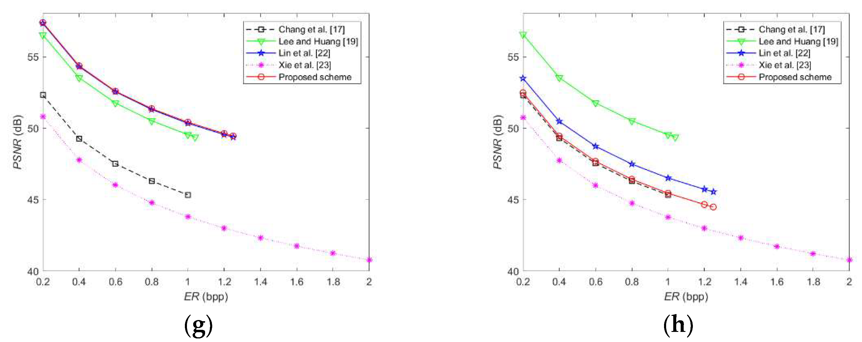
4.3. Comparison and Analysis
4.4. Discussions
4.4.1. Limited Capabilities Analysis
- The to-be-embedded secret messages, i.e., Msg, are too large. The larger the Msg is, the larger the sunflower area should be. In doing so, the visual quality of shadow images will be seriously distorted. This indicates that the system is not capable of keeping the trade-off between PSNR and ER;
- Cost of execution time. In order to construct the ET adaptively, both in data embedding and extraction stages, each pixel pair should determine the sunflower area and select the EPCs according to their types. This requires the additional cost of execution time.
4.4.2. Potential Failures Analysis
- Without the prior knowledge of the rule of constructing EPC and ET, in this case, the receiver cannot extract the secret messages or carry out image recovery;
- Only owning one shadow image. In this paper, the secret messages and image recovery was correctly performed only if both of the recipients release their own shadow image. Therefore, for any one receiver alone, there will be a failure to extract the hidden secret messages.
5. Conclusions
Author Contributions
Funding
Institutional Review Board Statement
Informed Consent Statement
Data Availability Statement
Conflicts of Interest
References
- Chang, C.C.; Liu, Y.; Nguyen, T.S. A novel turtle shell based scheme for data hiding. In Proceedings of the 2014 Tenth International Conference on Intelligent Information Hiding and Multimedia Signal Processing, Kitakyushu, Japan, 27–29 August 2014; pp. 89–93. [Google Scholar]
- Duan, X.; Li, B.; Xie, Z.; Yue, D.; Ma, Y. High-capacity information hiding based on residual network. IETE Tech. Rev. 2021, 38, 172–183. [Google Scholar] [CrossRef]
- Ge, X.; Yu, J.; Hao, R.; Lv, H. Verifiable Keyword search supporting sensitive information hiding for the cloud-based healthcare sharing system. IEEE Trans. Ind. Inform. 2021. [Google Scholar] [CrossRef]
- Chang, C.C.; Li, C.T.; Shi, Y.Q. Privacy-aware reversible watermarking in cloud computing environments. IEEE Access 2018, 6, 70720–70733. [Google Scholar] [CrossRef]
- Chang, C.C. Adversarial learning for invertible steganography. IEEE Access 2020, 8, 198425–198435. [Google Scholar] [CrossRef]
- Chang, C.C.; Li, C.T.; Chen, K. Privacy-preserving reversible information hiding based on arithmetic of quadratic residues. IEEE Access 2019, 7, 54117–54132. [Google Scholar] [CrossRef]
- Hu, Y.; Lee, H.K.; Chen, K.; Li, J. Difference expansion based reversible data hiding using two embedding directions. IEEE Trans. Multimed. 2008, 10, 1500–1512. [Google Scholar] [CrossRef]
- Lee, C.F.; Chen, H.L.; Tso, H.K. Embedding capacity raising in reversible data hiding based on prediction of difference expansion. J. Syst. Softw. 2010, 83, 1864–1872. [Google Scholar] [CrossRef]
- Ou, B.; Li, X.; Zhao, Y.; Ni, R.; Shi, Y.Q. Pairwise prediction-error expansion for efficient reversible data hiding. IEEE Trans. Image Process. 2013, 22, 5010–5021. [Google Scholar] [CrossRef]
- Chang, Q.; Li, X.; Zhao, Y.; Ni, R. Adaptive pairwise prediction-error expansion and multiple histograms modification for reversible data hiding. IEEE Trans. Circuits Syst. Video Technol. 2021, 31, 4850–4863. [Google Scholar] [CrossRef]
- Wang, J.; Ni, J.; Zhang, X.; Shi, Y.Q. Rate and distortion optimization for reversible data hiding using multiple histogram shifting. IEEE Trans. Cybern. 2016, 47, 315–326. [Google Scholar] [CrossRef]
- Peng, F.; Zhao, Y.; Zhang, X.; Long, M.; Pan, W.Q. Reversible data hiding based on RSBEMD coding and adaptive multi-segment left and right histogram shifting. Signal Process. Image Commun. 2020, 81, 115715. [Google Scholar] [CrossRef]
- Qu, X.; Kim, H.J. Pixel-based pixel value ordering predictor for high-fidelity reversible data hiding. Signal Process. 2015, 111, 249–260. [Google Scholar] [CrossRef]
- Chang, J.; Ding, F.; Li, X.; Zhu, G. Hybrid prediction-based pixel-value-ordering method for reversible data hiding. J. Vis. Commun. Image Represent. 2021, 77, 103097. [Google Scholar] [CrossRef]
- Chang, C.C. Cryptospace invertible steganography with conditional generative adversarial networks. Secur. Commun. Netw. 2021, 2021, 5538720. [Google Scholar] [CrossRef] [PubMed]
- Chang, C.C. Neural reversible steganography with long short-term memory. Secur. Commun. Netw. 2021, 2021, 5580272. [Google Scholar] [CrossRef]
- Chang, C.C.; Kieu, T.D.; Chou, Y.C. Reversible data hiding scheme using two steganographic images. In Proceedings of the Tencon 2007–IEEE Region 10 Conference, Taipei, Taiwan, 30 October–2 November 2007; pp. 1–4. [Google Scholar]
- Lee, C.F.; Wang, K.H.; Chang, C.C.; Huang, Y.L. A reversible data hiding scheme based on dual steganographic images. In Proceedings of the 3rd International Conference on Ubiquitous Information Management and Communication, Suwon, Korea, 15–16 January 2009; pp. 228–237. [Google Scholar]
- Lee, C.F.; Huang, Y.L. Reversible data hiding scheme based on dual stegano-images using orientation combinations. Telecommun. Syst. 2013, 52, 2237–2247. [Google Scholar] [CrossRef]
- Liu, Y.; Chang, C.C. A turtle shell-based visual secret sharing scheme with reversibility and authentication. Multimed. Tools Appl. 2018, 77, 25295–25310. [Google Scholar] [CrossRef]
- Su, G.D.; Liu, Y.; Chang, C.C. A square lattice oriented reversible information hiding scheme with reversibility and adaptivity for dual images. J. Vis. Commun. Image Represent. 2019, 64, 102618. [Google Scholar] [CrossRef]
- Lin, J.Y.; Liu, Y.; Chang, C.C. A real-time dual-image-based reversible data hiding scheme using turtle shells. J. Real-Time Image Process. 2019, 16, 673–684. [Google Scholar] [CrossRef]
- Xie, X.Z.; Chang, C.C. Hiding data in dual images based on turtle shell matrix with high embedding capacity and reversibility. Multimed. Tools Appl. 2021, 80, 36567–36584. [Google Scholar] [CrossRef]
- Chen, X.; Guo, W. Reversible data hiding scheme based on fully exploiting the orientation combinations of dual stego-images. Int. J. Netw. Secur. 2020, 22, 126–135. [Google Scholar]
- Chen, X.; Hong, C. An efficient dual-image reversible data hiding scheme based on exploiting modification direction. J. Inf. Secur. Appl. 2021, 58, 102702. [Google Scholar] [CrossRef]
- Chang, C.C.; Li, C.T. Algebraic secret sharing using privacy homomorphisms for IoT-based healthcare systems. Math. Biosci. Eng. 2019, 16, 3367–3381. [Google Scholar] [CrossRef] [PubMed]
- Fridrich, J.; Goljan, M.; Du, R. Detecting LSB steganography in color, and gray-scale images. IEEE Multimed. 2001, 8, 22–28. [Google Scholar] [CrossRef] [Green Version]
- Lou, D.C.; Hu, C.H. LSB steganographic method based on reversible histogram transformation function for resisting statistical steganalysis. Inf. Sci. 2012, 188, 346–358. [Google Scholar] [CrossRef]


| Primary Mark | Foreign Mark | ||||
|---|---|---|---|---|---|
| 0 | 00000 | 0 | 0 | ||
| 1 | 00001 | 1 | |||
| 2 | 00010 | 2 | |||
| 3 | 00011 | 3 | |||
| 4 | 00100 | 4 | |||
| 5 | 00101 | 5 | |||
| 6 | 00110 | 6 | |||
| 7 | 00111 | 7 | |||
| 8 | 01000 | 8 | |||
| 9 | 01001 | 1 | 3 | ||
| 10 | 01010 | 6 | |||
| 11 | 01011 | 7 | |||
| 12 | 01100 | 2 | 4 | ||
| 13 | 01101 | 7 | |||
| 14 | 01110 | 8 | |||
| 15 | 01111 | 3 | 1 | ||
| 16 | 10000 | 5 | |||
| 17 | 10001 | 8 | |||
| 18 | 1001 | 4 | 2 | ||
| 19 | 1010 | 5 | |||
| 20 | 1011 | 6 | |||
| 21 | 1100 | 5 | 7 | ||
| 22 | 1101 | 6 | 8 | ||
| 23 | 1110 | 7 | 5 | ||
| 24 | 1111 | 8 | 6 |
| 0 | 0 | 21 | 5 | 42 | 9 | |||
| 1 | 1 | 22 | 5 | 43 | 9 | |||
| 2 | 1 | 23 | 5 | 44 | 10 | |||
| 3 | 1 | 24 | 5 | 45 | 10 | |||
| 4 | 1 | 25 | 5 | 46 | 10 | |||
| 5 | 1 | 26 | 5 | 47 | 10 | |||
| 6 | 1 | 27 | 5 | 48 | 10 | |||
| 7 | 1 | 28 | 5 | 49 | 10 | |||
| 8 | 2 | 29 | 5 | 50 | 10 | |||
| 9 | 2 | 30 | 8 | 51 | 10 | |||
| 10 | 2 | 31 | 8 | 52 | 10 | |||
| 11 | 2 | 32 | 8 | 53 | 10 | |||
| 12 | 2 | 33 | 8 | 54 | 13 | |||
| 13 | 2 | 34 | 8 | 55 | 13 | |||
| 14 | 4 | 35 | 8 | 56 | 13 | |||
| 15 | 4 | 36 | 8 | 57 | 13 | |||
| 16 | 4 | 37 | 8 | 58 | 17 | |||
| 17 | 4 | 38 | 9 | 59 | 17 | |||
| 18 | 4 | 39 | 9 | 60 | 17 | |||
| 19 | 4 | 40 | 9 | 61 | 17 | |||
| 20 | 5 | 41 |
| 0 | 0 | 8 | 5 | ||
| 1 | 1 | 9 | 5 | ||
| 2 | 2 | 10 | 5 | ||
| 3 | 2 | 11 | 5 | ||
| 4 | 4 | 12 | 9 | ||
| 5 | 4 | 13 | 10 | ||
| 6 | 5 | 14 | 10 | ||
| 7 | 5 | 15 | 16 |
| Test Images | Entropy | Relative Entropy | ||||
|---|---|---|---|---|---|---|
| C | S1 | S2 | (C, S1) | (C, S2) | (S1, S2) | |
| Airplane | 6.7059 | 6.7129 | 6.7286 | 0.0007 | 0.0054 | 0.0039 |
| Baboon | 7.1391 | 7.1404 | 7.1425 | 0.0003 | 0.0008 | 0.0009 |
| Goldhill | 7.4778 | 7.4811 | 7.4869 | 0.0006 | 0.0033 | 0.0024 |
| Barbara | 7.6321 | 7.6341 | 7.6377 | 0.0002 | 0.0014 | 0.0013 |
| Elaine | 7.4980 | 7.4991 | 7.5011 | 0.0003 | 0.0012 | 0.0012 |
| Lena | 7.4455 | 7.4477 | 7.4513 | 0.0003 | 0.0011 | 0.0011 |
| Peppers | 7.5944 | 7.5964 | 7.6006 | 0.0002 | 0.0016 | 0.0016 |
| Wine | 7.4649 | 7.4681 | 7.4747 | 0.0010 | 0.0038 | 0.0043 |
| Average | 7.3697 | 7.3725 | 7.3779 | 0.0004 | 0.0023 | 0.0021 |
| Test Images | ER | PSNR/SSIM (S1) | PSNR/SSIM (S2) | ER | PSNR/SSIM (S1) | PSNR/SSIM (S2) | ER | PSNR/SSIM (S1) | PSNR/SSIM (S2) |
|---|---|---|---|---|---|---|---|---|---|
| Airplane | 0.20 | 57.38/0.9997 | 52.47/0.9992 | 1.00 | 50.41/0.9989 | 45.47/0.9965 | 1.25 | 49.44/0.9986 | 44.49/0.9957 |
| Baboon | 0.20 | 57.38/1.0000 | 52.48/0.9999 | 1.00 | 50.42/0.9996 | 45.460.9986 | 1.25 | 49.46/0.9994 | 44.49/0.9983 |
| Goldhill | 0.20 | 57.42/0.9998 | 52.44/0.9994 | 1.00 | 50.39/0.9994 | 45.470.9981 | 1.25 | 49.44/0.9992 | 44.500.9976 |
| Barbara | 0.20 | 57.38/0.9999 | 52.48/0.9996 | 1.00 | 50.42/0.9994 | 45.47/0.9981 | 1.25 | 49.450.9992 | 44.50/0.9976 |
| Elaine | 0.20 | 57.42/0.9998 | 52.44/0.9994 | 1.00 | 50.45/0.9991 | 45.45/0.9972 | 1.25 | 49.49/0.9989 | 44.48/0.9966 |
| Lena | 0.20 | 57.33/0.9997 | 52.47/0.9991 | 1.00 | 50.39/0.9990 | 45.47/0.9969 | 1.25 | 49.43/0.9988 | 44.50/0.9963 |
| Peppers | 0.20 | 57.47/0.9998 | 52.45/0.9994 | 1.00 | 50.45/0.9990 | 45.45/0.9970 | 1.25 | 49.48/0.9988 | 44.48/0.9963 |
| Wine | 0.20 | 57.39/0.9999 | 52.44/0.9995 | 1.00 | 50.430.9991 | 45.460.9973 | 1.25 | 49.47/0.9988 | 44.50/0.9964 |
| Average | 0.20 | 57.40/0.9998 | 52.46/0.9994 | 1.00 | 50.42/0.9992 | 45.46/0.9975 | 1.25 | 49.46/0.9990 | 44.49/0.9968 |
| Test Images | Chang et al. [17] | Lee and Huang [19] | Lin et al. [22] | Xie et al. [23] | Chen and Guo [24] | Chen and Hong [25] | Proposed Scheme |
|---|---|---|---|---|---|---|---|
| Airplane | 1.00 | 1.04 | 1.25 | 2.00 | 1.14 | 1.56 | 1.25 |
| Baboon | 1.00 | 1.04 | 1.25 | 2.00 | 1.14 | 1.56 | 1.25 |
| Goldhill | 1.00 | 1.04 | 1.25 | 2.00 | 1.14 | 1.56 | 1.25 |
| Barbara | 1.00 | 1.04 | 1.25 | 2.00 | 1.14 | 1.56 | 1.25 |
| Elaine | 1.00 | 1.04 | 1.25 | 2.00 | 1.14 | 1.56 | 1.25 |
| Lena | 1.00 | 1.04 | 1.25 | 2.00 | 1.14 | 1.56 | 1.25 |
| Peppers | 1.00 | 1.04 | 1.25 | 2.00 | 1.14 | 1.56 | 1.25 |
| Wine | 1.00 | 1.04 | 1.25 | 2.00 | 1.14 | 1.56 | 1.25 |
| Average | 1.00 | 1.04 | 1.25 | 2.00 | 1.14 | 1.56 | 1.25 |
| Test Images | Chang et al. [17] | Lee and Huang [19] | Lin et al. [22] | Xie et al. [23] | Chen and Guo [24] | Chen and Hong [25] | Proposed Scheme | |||||||
|---|---|---|---|---|---|---|---|---|---|---|---|---|---|---|
| S1 | S2 | S1 | S2 | S1 | S2 | S1 | S2 | S1 | S2 | S1 | S2 | S1 | S2 | |
| Airplane | 45.32 | 45.34 | 49.38 | 49.38 | 49.39 | 45.54 | 40.80 | 40.81 | 49.91 | 49.92 | 43.40 | 43.45 | 49.44 | 44.49 |
| Baboon | 45.34 | 45.34 | 49.38 | 49.38 | 49.38 | 45.55 | 40.80 | 40.78 | 49.91 | 49.92 | 43.39 | 43.42 | 49.46 | 44.49 |
| Goldhill | 45.35 | 45.34 | 49.38 | 49.38 | 49.38 | 45.55 | 40.79 | 40.79 | 49.91 | 49.92 | 43.39 | 43.43 | 49.44 | 44.50 |
| Barbara | 45.32 | 45.32 | 49.38 | 49.38 | 49.39 | 45.55 | 40.79 | 40.78 | 49.91 | 49.92 | 43.42 | 43.44 | 49.45 | 44.50 |
| Elaine | 45.33 | 45.34 | 49.38 | 49.38 | 49.38 | 45.55 | 40.79 | 40.79 | 49.91 | 49.92 | 43.40 | 43.43 | 49.49 | 44.48 |
| Lena | 45.32 | 45.32 | 49.38 | 49.38 | 49.38 | 45.54 | 40.80 | 40.80 | 49.91 | 49.92 | 43.41 | 43.41 | 49.43 | 44.50 |
| Peppers | 45.32 | 45.35 | 49.38 | 49.38 | 49.38 | 45.55 | 40.80 | 40.80 | 49.91 | 49.92 | 43.42 | 43.41 | 49.48 | 44.48 |
| Wine | 45.33 | 45.34 | 49.38 | 49.38 | 49.38 | 45.55 | 40.80 | 40.80 | 49.91 | 49.92 | 43.41 | 43.42 | 49.47 | 44.50 |
| Average | 45.33 | 45.33 | 49.38 | 49.38 | 49.38 | 45.55 | 40.80 | 40.80 | 49.91 | 49.92 | 43.40 | 43.43 | 49.46 | 44.49 |
| Test Images | Lin et al. [22] | Chen and Hong [25] | Proposed Scheme | |||
|---|---|---|---|---|---|---|
| S1 | S2 | S1 | S2 | S1 | S2 | |
| Airplane | 49.39 | 45.54 | 44.36 | 44.41 | 49.44 | 44.49 |
| Baboon | 49.38 | 45.55 | 44.34 | 44.38 | 49.46 | 44.49 |
| Goldhill | 49.38 | 45.55 | 44.35 | 44.40 | 49.44 | 44.50 |
| Barbara | 49.39 | 45.55 | 44.38 | 44.40 | 49.45 | 44.50 |
| Elaine | 49.38 | 45.55 | 44.37 | 44.40 | 49.49 | 44.48 |
| Lena | 49.38 | 45.54 | 44.37 | 44.38 | 49.43 | 44.50 |
| Peppers | 49.38 | 45.55 | 44.39 | 44.37 | 49.48 | 44.48 |
| Wine | 49.38 | 45.55 | 44.37 | 44.39 | 49.47 | 44.50 |
| Average | 49.38 | 45.55 | 44.37 | 44.39 | 49.46 | 44.49 |
| Test Images | Chang et al. [17] | Lee and Huang [19] | Lin et al. [22] | Xie et al. [23] | Chen and Hong [25] | Proposed Scheme |
|---|---|---|---|---|---|---|
| Airplane | 0.0533 | 0.7550 | 0.0445 | 0.1320 | 0.0800 | 0.5217 |
| Baboon | 0.0543 | 0.7655 | 0.0511 | 0.1203 | 0.0781 | 0.5230 |
| Goldhill | 0.0557 | 0.7475 | 0.0458 | 0.1198 | 0.0609 | 0.4869 |
| Barbara | 0.0530 | 0.7458 | 0.0493 | 0.1196 | 0.0605 | 0.5118 |
| Elaine | 0.0527 | 0.7429 | 0.0461 | 0.1213 | 0.0600 | 0.5338 |
| Lena | 0.0527 | 0.7327 | 0.0459 | 0.1205 | 0.0597 | 0.5036 |
| Peppers | 0.0523 | 0.7359 | 0.0459 | 0.1199 | 0.0660 | 0.5479 |
| Wine | 0.0566 | 0.7581 | 0.0432 | 0.1221 | 0.0720 | 0.5485 |
| Average | 0.0538 | 0.7479 | 0.0465 | 0.1219 | 0.0672 | 0.5222 |
Publisher’s Note: MDPI stays neutral with regard to jurisdictional claims in published maps and institutional affiliations. |
© 2022 by the authors. Licensee MDPI, Basel, Switzerland. This article is an open access article distributed under the terms and conditions of the Creative Commons Attribution (CC BY) license (https://creativecommons.org/licenses/by/4.0/).
Share and Cite
Chang, C.-C.; Su, G.-D.; Lin, C.-C.; Li, Y.-H. Position-Aware Guided Hiding Data Scheme with Reversibility and Adaptivity for Dual Images. Symmetry 2022, 14, 509. https://doi.org/10.3390/sym14030509
Chang C-C, Su G-D, Lin C-C, Li Y-H. Position-Aware Guided Hiding Data Scheme with Reversibility and Adaptivity for Dual Images. Symmetry. 2022; 14(3):509. https://doi.org/10.3390/sym14030509
Chicago/Turabian StyleChang, Chin-Chen, Guo-Dong Su, Chia-Chen Lin, and Yung-Hui Li. 2022. "Position-Aware Guided Hiding Data Scheme with Reversibility and Adaptivity for Dual Images" Symmetry 14, no. 3: 509. https://doi.org/10.3390/sym14030509