Article

LiDAR and Camera Fusion Approach for Object Distance Estimation in Self-Driving Vehicles

Division of Automotive Technology, DGIST, Daegu-42988, Korea
*
Author to whom correspondence should be addressed.
Symmetry 2020, 12(2), 324; https://doi.org/10.3390/sym12020324
Submission received: 3 January 2020 / Revised: 11 February 2020 / Accepted: 19 February 2020 / Published: 24 February 2020

Abstract

:
The fusion of light detection and ranging (LiDAR) and camera data in real-time is known to be a crucial process in many applications, such as in autonomous driving, industrial automation, and robotics. Especially in the case of autonomous vehicles, the efficient fusion of data from these two types of sensors is important to enabling the depth of objects as well as the detection of objects at short and long distances. As both the sensors are capable of capturing the different attributes of the environment simultaneously, the integration of those attributes with an efficient fusion approach greatly benefits the reliable and consistent perception of the environment. This paper presents a method to estimate the distance (depth) between a self-driving car and other vehicles, objects, and signboards on its path using the accurate fusion approach. Based on the geometrical transformation and projection, low-level sensor fusion was performed between a camera and LiDAR using a 3D marker. Further, the fusion information is utilized to estimate the distance of objects detected by the RefineDet detector. Finally, the accuracy and performance of the sensor fusion and distance estimation approach were evaluated in terms of quantitative and qualitative analysis by considering real road and simulation environment scenarios. Thus the proposed low-level sensor fusion, based on the computational geometric transformation and projection for object distance estimation proves to be a promising solution for enabling reliable and consistent environment perception ability for autonomous vehicles.

1. Introduction

In recent years, many researchers have become interested in multi-sensor data convergence and data integration technologies based on sensors such as cameras, light detection and ranging (LiDAR), and radar as sensing technologies have developed for environment perception [1]. In particular, in robots and autonomous systems, the complementary modality between sensors is an important issue. Especially in intelligent vehicles, object detection must be fast and accurate enough to enable the control system to react and perform the required corrections. However current state-of-the-art literature describes a highly accurate object detection system using vision and range sensing sensors, though there are still several issues to be solved in the context of autonomous driving. For example, detecting the object distance is one limitation of the current object detection approaches. Regarding object distance estimation, there are several approaches that have been proposed, depending on the modality of the sensors used, such as radar, LiDAR, or camera. Each sensor modality is capable of perceiving the environment with a specific perspective and is limited by detecting certain attribute information of objects. More specifically, vision-based approaches are more robust and accurate in object detection but fail in estimating the distance of the object accurately. In contrast, LiDAR-based methods are very robust and accurate in measuring the distance of the object but are limited by the object classification ability. As an alternative, there are a few approaches based on the stereo vision camera because of its ability to perceive the environment in 3D [2]. However, the main constraint is the real-time processing of dense frames and measurement and estimation errors [3]. Hence, considering the ability and limitation of the camera and LiDAR sensor, the sensor-fusion-based approach appears to be ideal for addressing object detection at a distance from the vehicle’s current position. In addition, sensor fusion approaches broadly are classified into three main categories based on the different levels of data used for fusion, namely low-level fusion, feature-level fusion, and high-level fusion [4,5]. In the low-level fusion, the raw measurement from the sensors is fused based on the sensor’s physical location, and feature-level fusion extracts the certain feature from the raw measurement through a series of preprocessing. In the high-level fusion, each sensor independently carries out object detection or a tracking algorithm and then performs fusion. Although each fusion approach demonstrates well-known advantages and disadvantages when compared to each other, low-level fusion appears to be more optimal for autonomous vehicles because of its real-time performance and the more precise fusion of data.
However, it is possible to solve the problem of complementary modality and overcome the limitation of each sensor by fusing the advantages of the respective sensors. It is also possible to provide a great deal of information such as type, height, width, and distance of an object in the surrounding environment from the current position by using the fusion data acquired from these sensors [
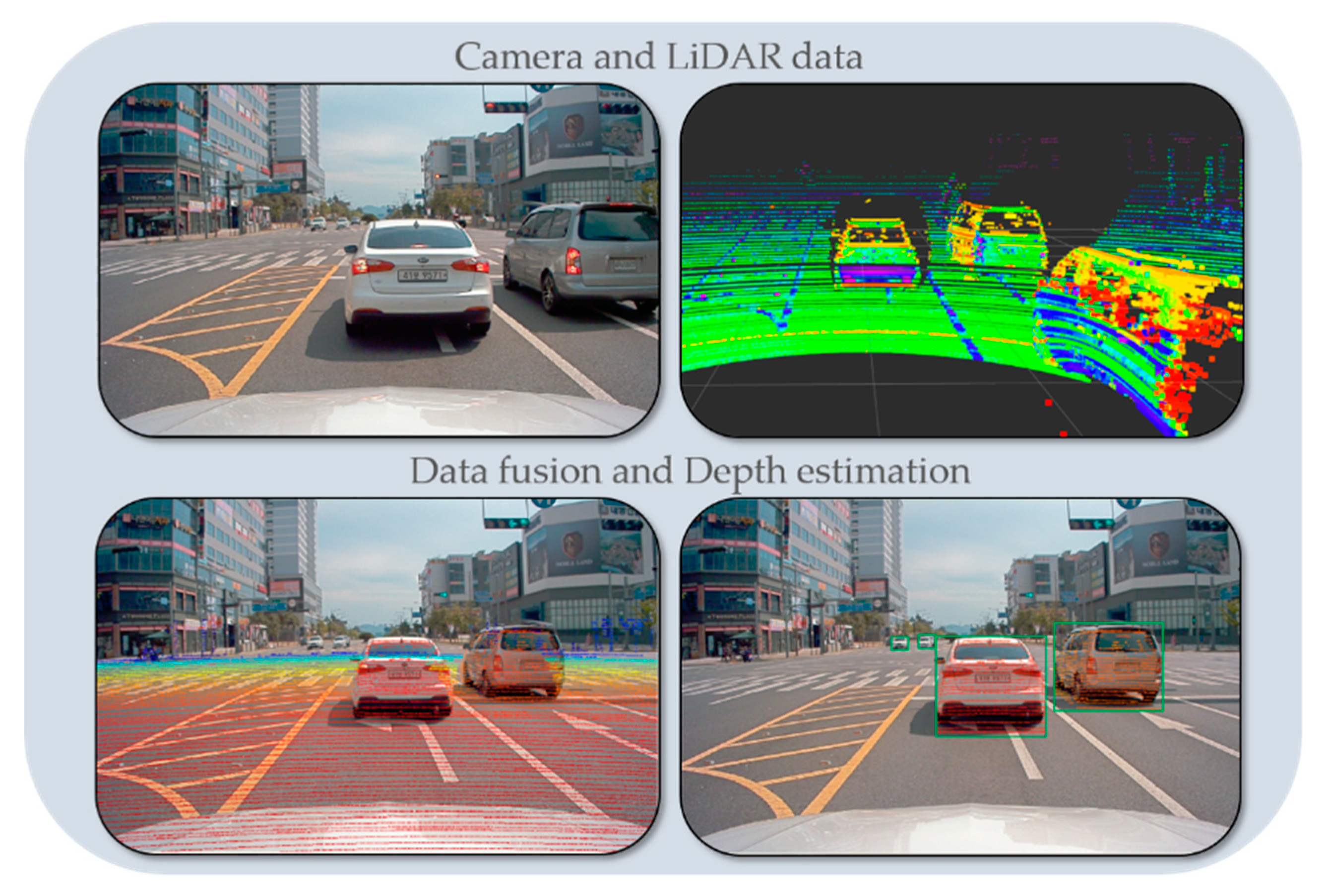
3]. For example, range sensors such as high-speed 3D LiDAR can be used with RGB cameras to enable a robot to perform various detection tasks. More specifically, a 3D LiDAR sensor can provide 3D position and depth information of classified objects, whereas RGB cameras provide 2D position and color information. Therefore, in the real world, the objects can be visualized by mapping information from the 3D position onto the 2D image. However, to fuse the information, it is necessary to find the relative positions and original directions of the sensors. As sensor fusion technology is applied to various fields, the calibration issue between sensors has become increasingly important. In particular, the development of fusion technology using cameras and LiDAR in autonomous vehicles requires an accurate relative position (including posture and direction information) of the camera and LiDAR sensor as an absolute necessity. This can be accomplished by finding the conversion matrix between heterogeneous sensors as extrinsic parameter problems. Therefore, to detect unique features in the point cloud data of LiDAR and the image data of the camera, it is necessary to determine an accurate corresponding relationship between the sensors. In this paper, we propose a precise data fusion method between a camera and a LiDAR sensor to estimate object distance, which is necessary to enable a self-driving vehicle driving along a real road by sensing its surrounding environment more precisely.
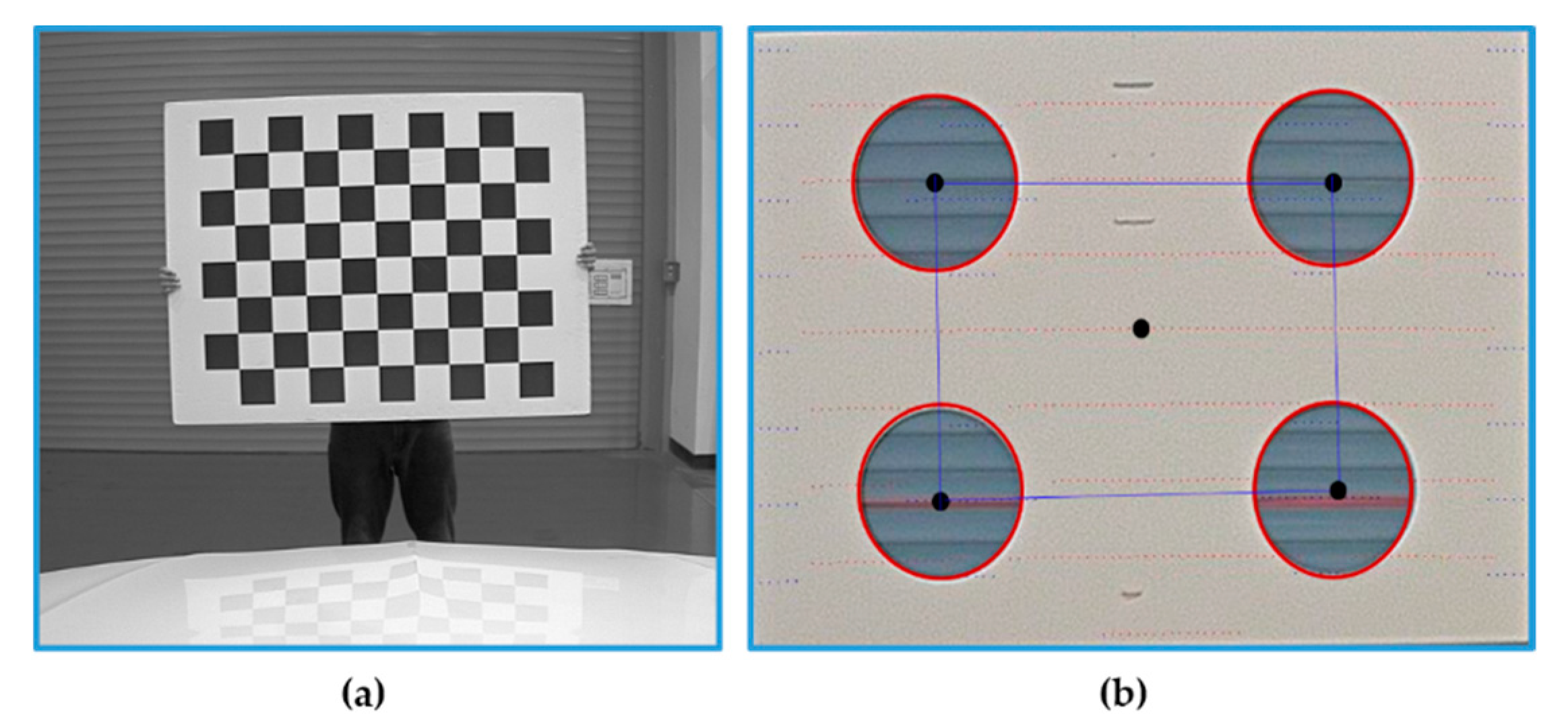
In order to estimate the object distance information, first, we consider fusing the data acquired from the camera and LiDAR sensor using the calibration matrix estimated by performing sensors calibration. In the sensor fusion approaches, it is very important to consider the relative position of sensors in order to fuse the data accurately. After sensor data fusion, the distance of an object in the vehicle’s path is detected utilizing the object detection output from the camera and distance data from the LiDAR. Hence, the object detection process requires an accurate sensor fusion approach to integrate camera and LiDAR data. For the fusion of camera and LiDAR data, studies have been shown that polygonal planes, such as a checkerboard or box, are necessary to perform the calibration between the camera and LiDAR. However, these methods either cause measurement errors or affect the calibration result whenever there are a few changes such as the plane position or the sensor’s relative position. In particular, if the positional change between the sensors is large, it is difficult to accurately detect the edge of the plane and to precisely calibrate the sensors. In addition, remote targets with different shapes and colors may generate different fusion results because of the various experimental environments and characteristics of the sensors. Therefore, in order to improve the accuracy of the calibration, the previously proposed methods are performed by mounting the sensors as close to each other as possible. In addition, it is difficult to apply the previous calibration methods to an autonomous driving system, which requires the recognition of distant objects, because the methods are performed after arranging the sensors closely and detecting the short-distance objects in the field of view. In this paper, correspondence between the sensors positioned in large displacement was established by performing the precise calibration using 3D marker.
However, the calibration approach seems to be more common but there is few research found regarding sensor fusion for object distance estimation, as well as with a limited experimental evaluation. Hence, understanding the necessity of the sensor fusion approach in the context of object distance estimation for the autonomous vehicle, in this article, we present, in detail, a pipeline for object distance estimation in autonomous vehicles by using a sensor fusion approach. It is based on detailed experimental evaluation using a 3D marker-based calibration and sensor-fusion-based distance estimation to recognize short- and long-distance objects, as required by an autonomous driving system. Experimental results and analysis based on the real and simulated environment in the article help the readers to understand the ability of the sensor fusion approach in distance estimation and further direction for improvements. 
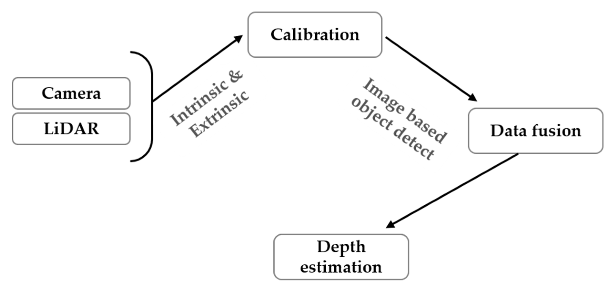
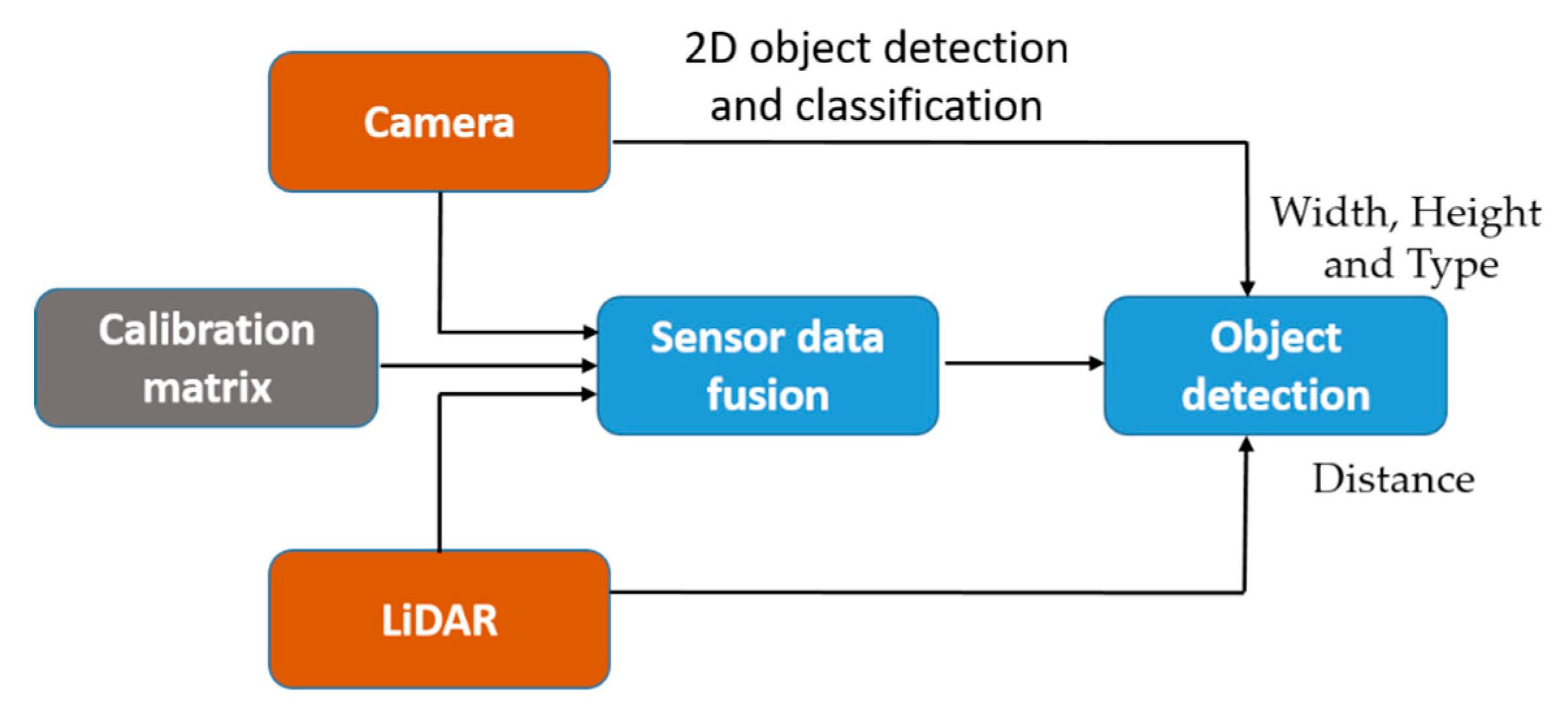
Figure 1 shows the overall process flow of the proposed technology including the data fusion-based depth estimation method and an alignment score-based accuracy evaluation method.
Section 2 describes previous sensor fusion methods and related techniques used for object distance estimation, and Section 3 presents our proposed method to fuse the data acquired by the camera and LiDAR of a self-driving vehicle. A detailed description of the approach follows to evaluate the effectiveness of the data fusion is provided. Section 4 discusses the evaluation of the distance estimation method in terms of quantity and qualitative analysis. Additionally, detailed experimental results are presented based on the real and simulated environment to provide insightful information to the readers. Section 5 contains the conclusion and alludes to future work.

2. Related Work

Autonomous vehicles use various sensors, such as LiDAR, radar, cameras, and ultrasonic sensors, to map and recognize the environment surrounding the vehicle [5]. In this field, sensor fusion techniques, in particular, have been proposed for object detection, and in other areas such as localization and path planning. For instance, conventional LiDAR and radar fusion focus on detecting moving objects such as vehicles and motorcycles. At that time, for the object detection, the velocity is fused using Doppler information extracted from radar and the width and length of vehicles obtained from LiDAR. In the article [6], the authors introduced RoadPlot-DATMO for moving object detection using multiple LiDAR sensors. However, multiple LiDAR sensor-based object detection and tracking were limited by object classification ability. Among the more recent approaches, the stereo-vision based method seems to be more suitable for generic object detection because of its ability to represent a scene in 3D but real-time performance is a critical issue [7]. In addition, the collaborative fusion between the laser scanner and camera approach presented in [8] limited to vehicle detection, though it is difficult to detect static objects such as pedestrians, motorcyclists, and so on.
As an alternative, considering real-time performance, object detection, classification ability, and accurate distance estimation, LiDAR and camera fusion techniques have been introduced for object detection based on different levels of data fusion. The fusion technique establishes a correspondence between the 3D points from LiDAR to the object detected by a camera to reduce the entire processing time. This is possible because sensor fusion compensates for the disadvantages between the sensors and improves the robustness and detection accuracy. For example, the resolution of a typical camera is considerably higher than that of LiDAR, but the camera has a limited field of view and cannot precisely estimate the distance to objects in comparison with LiDAR. In addition, a camera is very sensitive to light changes and has complex image processing in the case of using only images, and LiDAR has difficulty recognizing color and classifying objects in comparison with a camera. However, by using sensor fusion, it is possible not only to acquire complementary information about the environment surrounding an autonomous vehicle by using sensor data with different characteristics, but also to overcome the limitations of each sensor and to reduce the uncertainty of individual sensors. Therefore, an autonomous vehicle inevitably requires sensor fusion technology for safety and reliability. In the paper [3], the author proposed cooperative fusion for multi-objects detection by means of stereo vision and a laser scanner based on feature-level fusion. However, this approach requires sensors to extract the feature from the raw measurement. Another fusion method based on fuzzy logic was proposed in the article [9], which parses the image and point cloud data independently for object detection and performs fusion to get the distance of the object. In this study, sensors data fusion at low-level presented for the robust object detection and the method is verified with the on-road experiment.
In order to fuse the camera and LiDAR data at the low-level, the first essential step of the fusion process is extrinsic calibration between sensors. This means that the geometrical parameters such as the position and orientation of each sensor must be determined by taking into account the relative position and orientation of the other sensors [10,11,12]. Therefore, calibration for fusing sensor data is performed by finding the correspondence between the 3D points and 2D image pixels. The important point for fusing heterogeneous sensor data is to identify the features from each sensor and determine the geometric relation between the sensors [13]. A normal solution is to recognize a target with heterogeneous sensors and then match the data collected from different angles and positions.
In this paper, we focus on precise distance estimation as well as object detection in the path of an autonomous vehicle. In particular, in sensor data fusion, to estimate the depth of moving objects, the accuracy of calibration between sensors is very important. Most calibration methods check the correspondence between the two sensors by using external objects such as a trihedral rig [14,15,16], circles, board patterns [17,18], checkerboard, and others [19,20,21]. Typical methods for fusing the data of a camera with data from other sensors have used a calibration technique using checkerboard patterns. The board is used to fuse data acquired by the optical camera with that from the 2D laser scanner, and the calibration method is based on nonlinear least-squares optimization [22]. To avoid the many errors caused by the checkerboard pattern, a black circular plane board is used, which locates the object by estimating the 3D coordinates of the center of the circle and the vector normal to the plane [23]. In addition, most researchers use the well-known Levenberg–Marquardt algorithm to improve calibration accuracy when transforming LiDAR and camera coordinates [24,25]. Recently, many researchers have also proposed automatic calibration methods [26]. These methods find the target object because each sensor automatically detects the center of the object and circles on a plane. The random sample consensus (RANSAC) algorithm is used to extract the plane, and the iterative closest point (ICP) algorithm based on nonlinear optimization is employed to accurately refine the external parameters for data fusion [16,27]. Another approach to automatic calibration is to use a plane with four circular holes on a white background [
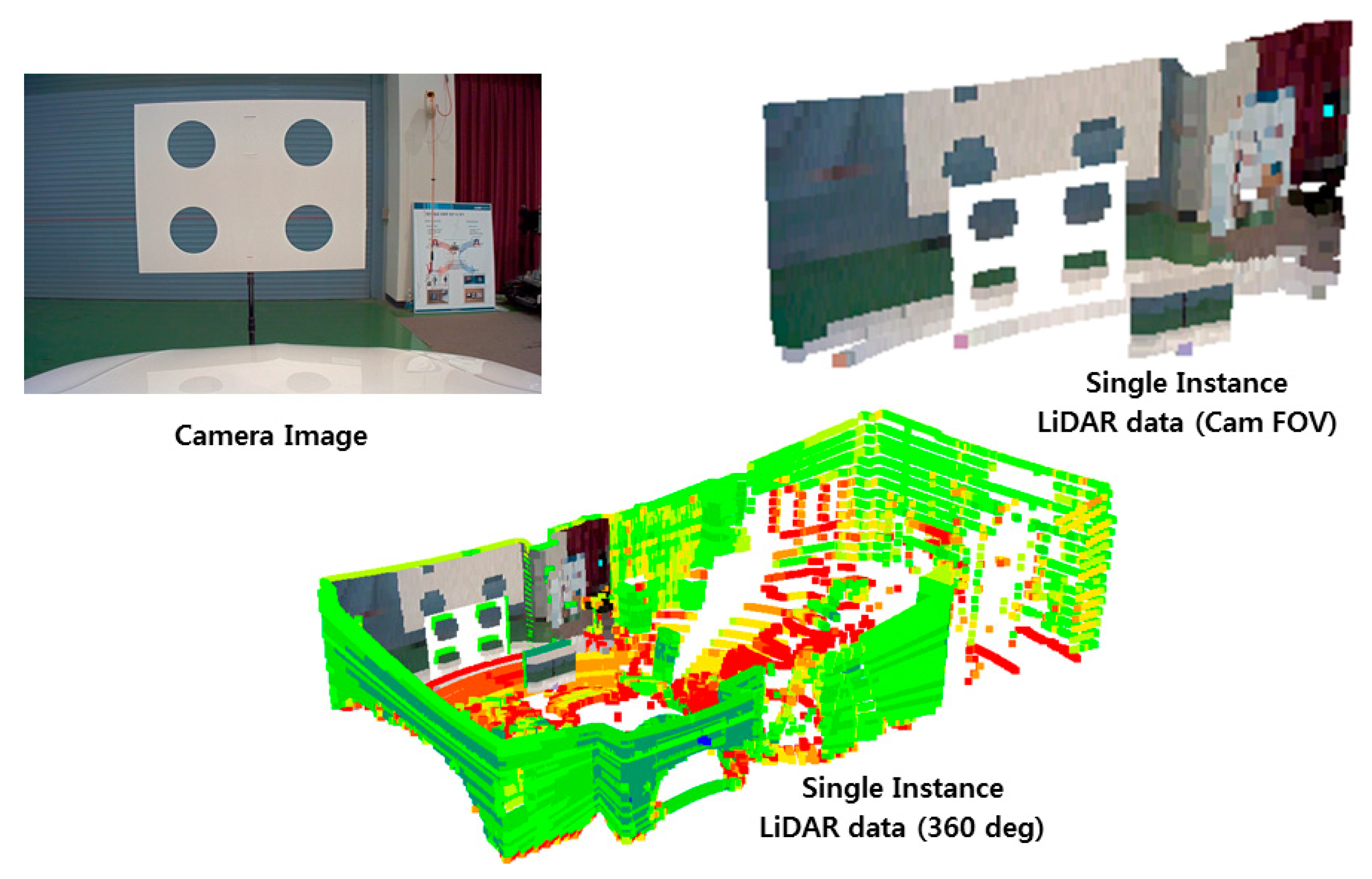
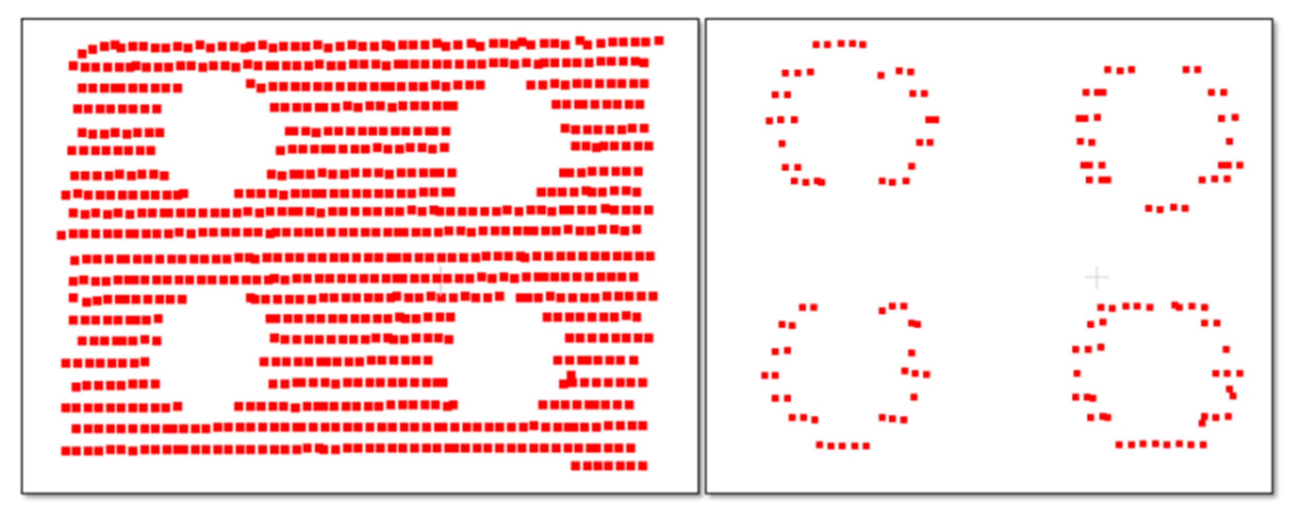
28]. This enables 3D LiDAR point cloud data and camera images to detect the four holes automatically but requires high-resolution LiDAR. Another calibration method uses single-scan data of LiDAR and data captured once by the camera [29]. This requires multiple checkerboards and two cameras installed in different positions. An alternative calibration method uses a stereo camera and LiDAR. The method constructs a 3D scene from camera data by using the speeded-up robust features (SURF) algorithm, and this is matched with LiDAR and camera data by applying the ICP algorithm to fuse the data [26,30,31]. These studies have only focused on improving the accuracy of data fusion between sensors for object detection. However, most of the previous methods performed calibration between sensors in a limited space [32,33,34,35] and these methods have not been shown to accurately perform with experiments in real-time dataset [36] and have not been compared with other methods. In addition, in conventional fusion methods, because calibration and data fusion is performed by mounting the sensors as close to each other as possible to improve the detection accuracy of an object, only objects located within a short distance can be recognized [37]. Therefore, the previous methods are not suitable for autonomous vehicle platforms that need to recognize distant objects and to detect them in real-time.
In this study, we determine 3D marker types by carrying out various experiments to find the types of markers that can fuse the data with high accuracy regardless of the relative positions of the sensors. This 3D marker for detecting remote objects with LiDAR and camera is utilized for precise data fusion in the autonomous vehicle system. Then, we propose a method of fusing the data of the camera and LiDAR for detecting the surrounding objects and a method estimating the distance to objects detected by fusing data on a real road. In addition, we evaluate the performance of the data fusion method in various experiments while driving along an actual road using an autonomous vehicle platform. The experimental results show that the proposed methods can estimate the precise depth of objects and recognize objects accurately. Therefore, we demonstrate that the proposed methods to fuse camera and LIDAR data and to estimate the depth of objects have the potential to be used in a self-driving vehicle.

3. Sensor Data Fusion for Self-driving Vehicles

This section describes the proposed method for self-driving vehicles in detail. The method perceives its surrounding situation by capturing the various physical attributes of the environment using LiDAR and camera sensors. As shown in Figure 2, the first step of the algorithm involves calibrating the LiDAR and camera sensors to measure the sensor displacement using the 3D marker. Next, based on the calibration parameter and the camera’s intrinsic parameter, the LiDAR point cloud is mapped onto the camera image. The accuracy and usefulness of the proposed method are evaluated by using pixel-to-point matching of the sensor data and an alignment score estimation of the matched data.

3.1. The Calibration Method of the Camera and LiDAR

The calibration of LiDAR and the camera is performed in two consecutive steps in order to estimate the intrinsic and extrinsic calibration parameters. First, the camera intrinsic parameters are estimated by using the well-known checkerboard for the camera calibration method, and LiDAR and camera extrinsic parameters are obtained by using a planar 3D marker. The actual sensor placement on the roof of the vehicle is graphically illustrated in Figure 3, and the sensors were arranged as shown in Figure 4.
As shown in Figure 5, sensors were mounted rigidly on the top of the vehicle with mutual displacement. A Velodyne HDL 64E-S2 (Velodyne, San Jose, CA, USA) model LiDAR sensor and Sekonix SF3321 model of camera for video streaming were utilized in this work. The image data captured from the camera are represented by using a 2D coordinate system (U,V) and the 3D point cloud generated from the raw measurement of LiDAR sensors is presented by applying a 3D coordinate system (X,Y,Z). The main objective of the camera and LiDAR calibration is to compute the projective transformation matrix, which will project the 3D LiDAR points (X,Y,Z) onto the 2D image (U,V). The projective transformation matrix can be formulated as in Equation (1):
M p r o j e c t i v e   =   C int r i n s i c   ×   M e x t r i n s i c
c i ( U V 1 )   =   M p r o j e c t i v e   p i ( X Y Z 1 )
where M p r o j e c t i v e is the final projective matrix with a camera intrinsic matrix C int r i n s i c = [ f 0 u 0 0 0 f v 0 0 0 0 0 1 ] and camera and LiDAR extrinsic matrix M e x t r i n s i c   =   ( r 11 r 12 r 13 t x r 21 r 22 r 23 t y r 31 r 32 r 33 t z 0 0 0 1 ) , and c i and p i represent the camera image and LiDAR point cloud at a time i. Also, f u and f v are the focal lengths in horizontal and vertical directions, respectively, ( u 0 , v 0 ) is the center point of the image plane, ( r 11 r 33 ) represents the elements of the rotation matrix, and ( t x , t y , t z ) is translation parameters.

3.1.1. Estimation of Intrinsic and Extrinsic Parameters

In this paper, two different types of marker boards are used for the intrinsic and extrinsic parameter estimation. The internal characteristics of the camera, such as the focal length, skew distortion, and image center are estimated by the camera’s intrinsic calibration using the checkerboard marker shown in Figure 5a. This is an essential step in calibrating the LiDAR and camera for data fusion, and the calibration results contain the camera matrix, distortion coefficients, and camera projection matrix.
After the estimation of the intrinsic parameters of the camera, it is necessary to determine the extrinsic parameter; i.e., the six degrees of freedom (6DOF) relative transformation between LiDAR and the camera for data fusion. The extrinsic parameters were determined by using a planar marker board of size 20 × 20 cm and four equally sized circular holes with a size of 22 cm, as shown in Figure 5b. The main objective is to determine the 6DOF transformation parameters by detecting the circles on the marker from both of the sensing devices. Before the marker detection process, it is important to ensure that the marker board is completely within the field of view of both sensors, as described in Figure 6.

Marker Detection in the 3D Point Cloud

The circular holes in the planar marker board were detected in the point cloud data by using the edge detection algorithm described in the literature [26]. Circles can be detected more robustly by using the RANSAC sphere detection algorithm [30]. However, before detecting the circles, the preprocessing of the point cloud is necessary to remove unwanted data from the point cloud obtained from the raw sensor measurement. First, visible point cloud data with respect to the camera’s field of view are extracted using the camera’s intrinsic parameter I as in Equation (3). Figure 7 shows the visible point cloud highlighted in the RGB intensity values extracted from the camera image.
We consider that the original point cloud p i [ x y z 1 ] contains 360° field-of-view data and p v [ x y z 1 ] is the visible point cloud obtained with respect to the camera’s intrinsic parameters C int r i n s i c .
p v   =   C int r i n s i c   ×   p i
After obtaining the visible point cloud p v , the RANSAC plane segmentation algorithm is used to segment the planar marker board from the point cloud p v . Then, the planar board is further processed to remove the straight line, which may cause inaccuracies in the circle detection process. Finally, the point cloud of the planar board, from which the straight lines are removed, remains with very few points and is subjected to the RANSAC sphere detection algorithm to detect the four circles, as shown in Figure 8.
After detecting the circles from the point cloud, the distance between the centers of adjacent circles and the radii of the circles are verified. The circle detection algorithm terminates if the circles are successfully verified; otherwise, the algorithm returns to the beginning by discarding the currently detected circles. After successfully detecting the four circles, the average radius R is estimated to compute the distance d in Equation (5).

Marker Detection in the 2D Image

Marker detection in the camera images is performed using the Sobel edge detection operator, after which the circles are detected by using the Hough transform described in [38]. Finally, the four circles are centered, and the radius is verified. Figure 9 presents the circles detected in the camera image.
The detected four circles in the image are utilized to estimate the calibration parameters, as explained in the further sections. Detected circles are verified with the pre-defined threshold, and finally, the four valid circles are used to estimate the average radius r, which is used in Equation (5) for the estimation of distance d.

Translation Estimation

In this work, the LiDAR and camera configuration on the vehicle were established in the same orientation of the three axes; hence, the translational difference is much more significant than the rotational difference. The translation difference between the sensors is estimated as follows.
Considering Equation (1) and assuming rotational invariance, the equation can be rewritten as follows,
M p r o j e c t i v e   =   [ f 0 u 0 0 0 f v 0 0 0 0 0 1 ]   ×   [ 1 0 0 t x 0 1 0 t y 0 0 1 t z 0 0 0 1 ]
The only unknown variables in Equation (4) are the components of the translation vector ( t x   t y   t z ). These translation vectors are computed by using the distance measurement based on the circle radius detected on the marker described in the previous section.
Before computing the components of the translational vector t x   a n d   t y , t z is computed using the camera focal length f, and circle radius R and r estimated from the point cloud and image, respectively, where d is the distance to the marker, as shown in Figure 10.
d   =   f   ×   R r
where R is the radius of the marker. Considering the distance from LiDAR to marker d1 and from the camera to marker d2 obtained by using Equation (5), the component t z of the translation vector is obtained by using Equation (6) is as follows.
tz = d1d2
After obtaining t z , the remaining components of the translation vectors can be obtained by using Equation (7).
t x   =   ( t z + z ) ( x o x ) f   and   t y   =   ( t z + z ) ( y o y ) f
Finally, the three components of the translation vector t ( t x , t y , t z ) are estimated for all four circles in the camera. The average of these four vectors is used to fuse the LiDAR and camera data to estimate the depth of the object.

Rotation Estimation

After translation estimation, rotation parameters are estimated to increase the accuracy of the calibration parameters. In order to estimate the rotation, we utilized the common least-square best-fitting rigid body transformation. Similar to the 3D marker board detection process, the edges of the marker board are estimated in the point cloud using RANSAC and edges in the image are estimated using the Sobel operator.
Considering the boundary feature set from the LiDAR and camera—respectively, b i l   &   b i c —the rotation estimation function is minimized as in Equation (8).
( R , t )   =   arg   min i = 1 n   w i | | ( R b i l   +   t ) b i c | | 2
Next, we compute the weighted centered vectors,
b ¯ l = i = 1 n w i b i l i = 1 n w i   and   b ¯ c = i = 1 n w i b i c i = 1 n w i
Then, we compute the centered vectors as x i   =   b i l b ¯ l and y i   =   b i c b ¯ c , where w i > 0 are the weights for each point pair and i = 1   t o   n . By computing the covariance matrix S = X W Y T , X   a n d   Y are d   ×   n matrices that have x i   a n d   y i as columns, respectively, and W   =   d i a g ( w 1 , w 2 , w 3 .... w n ) . Finally, the rotation matrix can be obtained by taking the SVD (Singular Value Decomposition) of S = U V T and rotation r ,
c i ( U V 1 )   =   ( r 11 r 12 r 13 t x r 21 r 22 r 23 t y r 31 r 32 r 33 t z 0 0 0 1 ) p i ( X Y Z 1 )
Finally, the translation vectors t   a n d   r are substituted in Equation (10) to fuse the LiDAR and camera data for the depth estimation.

3.2. Fusion of LiDAR and Camera Data

After estimating the intrinsic and extrinsic parameters, the LiDAR data points are projected onto the camera image using Equation (12). An example of this fusion is illustrated in Figure 11. The efficient fusion of data captured from the multiple sensors is essential in order to build a comprehensive perception for the autonomous vehicle. The data fusion process is able to utilize the sensors’ redundant information positively to perceive the surrounding environment. Even though camera-based object detection and classification are very robust and efficient, it is difficult to obtain the accurate depth of detected objects. In contrast, the LiDAR sensor proves to be efficient in the estimation of the depth of objects but suffers in the classification of small and distant objects. Figure 11 shows a few scenarios. It is very difficult to estimate the depth of the object using only a camera or LiDAR. Hence, the fusion of the output from the camera and LiDAR greatly benefits object detection and classification in three dimensions. In this paper, the data fusion process is illustrated along with the image-based object detection and classification method presented in [39].
Initially, a raw measurement obtained from the sensor is in a standard polar coordinate form with ( r i , θ i , φ i ) as parameters, where r i represents geometric distance, θ i , a n d   φ i represents horizontal and vertical angle with respect to sensor coordinate system and points are converted to Cartesian coordinate from the polar coordinate.
After converting the LiDAR data into Cartesian coordinates, 3D points are mapped onto the image using the calibration parameters.
p 2 D ( u i v i 1 )   =   ( r 11 r 12 r 13 t x r 21 r 22 r 23 t y r 31 r 32 r 33 t z 0 0 0 1 ) p i ( x i y i z i 1 )
where, p 2 D is the 2D fusion representation of camera and LiDAR data, and u i and v i represent the 2D coordinates, it holds camera intensity and LiDAR point indices values.
Figure 11 shows the output of the camera and LiDAR sensor using the calibration parameters along with image-based object detection and classification. The upper images in Figure 11 show all the LiDAR points projected on the image, and the lower images in the figure describe only points within the bounding box of detected objects.

Distance Estimation

The purpose of the sensor fusion approach is to estimate the object distance by utilizing the camera and LiDAR sensor data. Figure 12 presents the overview of the object distance estimation and Figure 13 shows the fusion results of object detection and classification results from the camera and sensor calibration output of LiDAR 3D points. From the sensor fusion result, the depth of the object is calculated from the calibrated LiDAR 3D points aligned inside the bounding box detected from the camera. Object detection in the camera follows the approach presented in the paper [40,41], we have utilized the source code shared on GitHub [42] without any modification.
With the sensor calibration matrix m c a l i b   =   ( r 11 r 12 r 13 t x r 21 r 22 r 23 t y r 31 r 32 r 33 t z 0 0 0 1 ) , input LiDAR points f l i d a r 3 D ( x , y , z , i d ) with indices id projected to image plane using m c a l i b as f l i d a r 2 D ( x , y , i d ) , f c a m e r a ( u , v ) is monocular camera frames and o b j i is the list of detected objects.
Each detected o b j i is represented in the bounding box with as shown in Figure 13. Projected LiDAR points inside the bounding box are extracted to estimate the distance of the detected object using Equation (12).
We consider detected o b j i with bounding box coordinates ( k 1 , k 2 , k 3 , k 4 ) and 2D projected LiDAR points f l i d a r 2 D ( x , y , i d ) .
i d e x t r a c t e d   =   { i d i f l i d a r 2 D ( x , y , i d ) ,   i f   p 2 D , i f l i d a r 2 D ( x , y , i d )   i n s i d e   r e c t   ( k 1 , k 2 , k 3 , k 4 ) }
where i n s i d e   r e c t   ( k 1 , k 2 , k 3 , k 4 ) determines a point p 2 D , i f l i d a r 2 D ( x , y , i d ) , whether it lies inside the bounding box or not.
After extracting the indices i d e x t r a c t e d , corresponding 3D points extracted using to determine the distance o b j i , d i s t of the object
p 3 D , i f l i d a r 3 D ( x , y , z , i d )   { w h e r e   i d   =   i d f l i d a r 2 D ( x , y , i d ) } o b j i , d i s t   =   min Z   ( { p 3 D , i ( x , y , z ) : i = 1 , , n } )
Step by step algorithmic procedure for distance estimation shown in the Algorithm 1.
Algorithm 1: Depth estimation using sensor fusion data.
Object depth estimation using camera and LiDAR data
Input: Camera frame f i m a g e ( u , v ) with detected objects o b j i , Lidar frame f l i d a r 3 D ( x , y , z , i d ) at time t, M c a l i b is the final projective matrix obtained from the LiDAR and camera calibration.
Output: Depth o b j i , d i s t   { i = 1   t o   n } , n is the number of detected objects.
Method:
  1. For all the objects in o b j i , get the bounding box coordinates k [ r , c ] i of four corners.
  2. Project the input LiDAR points f l i d a r 3 D ( x , y , z , i d ) to f l i d a r 2 D ( x , y , i d ) using M c a l i b
  3. Extract the indices i d e x t r a c t e d from f l i d a r 2 D ( x , y , i d ) of the points lies inside the bounding box corners ( k 1 , k 2 , k 3 , k 4 )
  4. Extract the 3D points from f l i d a r 3 D ( x , y , z , i d ) corresponding to the extracted indices i d e x t r a c t e d
  5. Finally, compute the distance of the o b j i using from the extracted point as;
o b j i , d i s t   =   min Z ( { p 3 D , i ( x , y , z ) : i = 1 , , n } )

4. Experimental Results and Discussion

In this section, we describe the detailed experimental setup and performance evaluation process of the data fusion method within the context of depth sensing for an autonomous vehicle. Based on the current requirements of autonomous vehicles, the data fusion method was evaluated by considering the different aspects of environmental sensing.

4.1. Vehicle Platform Setup and Dataset Description

The fusion of LiDAR and camera data for an autonomous vehicle was performed with the hardware setup shown in Figure 14. The autonomous vehicle platform was equipped with a Velodyne HDL 64E- S2 model LiDAR sensor for 3D acquisition and a Sekonix SF3321 camera for video streaming. Both the LiDAR sensor and the camera were aligned and were forward-facing with respect to the vehicle. The positional displacement between the sensors is explained in detail in Figure 4. Prior to fusing the data acquired by the LiDAR and camera sensors, the sensors were calibrated to estimate the intrinsic and extrinsic parameters, as described in Section 3.
The experimental verification was conducted with the custom dataset acquired by utilizing the vehicle platform and the sensor setup described in Figure 14. Multiple on-road scenarios were captured at urban in Hyeonpung-eup, Daegu, Republic of Korea during the summer season in bright and sunny weather at a vehicle speed of 30 to 50 km/h. The camera frame rate was configured to 30 frames per second, whereas the Velodyne LiDAR capture rate was set to 10 frames per second. The images captured by the camera and data acquired by the LiDAR sensor are presented in Figure 15 on the left and right, respectively. In order to evaluate the performance of the data fusion, the dataset was collected by considering the size, type, and varied distance of objects. The ability of the data fusion technique to accurately determine the distance to objects was evaluated by considering factors such as the vehicle speed and operating frequency of each sensor.

4.2. Accuracy Evaluation

Evaluation of Pixel-to-Point Correspondence
Tracking and estimating the distance of stationary and moving objects are a critical functionality of autonomous driving technology. In this evaluation, the accuracy of the data fusion method was verified by considering factors related to the distance of objects. The evaluation results presented in the table are the results of a statistical analysis of the data fusion accuracy when the distance of an object is varied, as shown in Figure 16.
Table 1 shows the results of the accuracy analysis of the LiDAR pixel-to-point correspondence process when the distance to objects is varied. In this evaluation, a planar marker board considered as a target object with the dimensions 1 m × 1.5 m was used in three test cases by varying the distance at 20, 40, and 60 m from the vehicle. The corners of the planar marker board were highlighted with green-colored markings for reference in the camera image, and the corresponding corner points in LiDAR were referenced using point cloud indices. After fusing the camera and LiDAR data, each reference point from the camera and the LiDAR points were compared to estimate the accuracy of the alignment. The statistical analysis provided in Table 1 shows that, as distance increases, the point-to-pixel correspondence is difficult to determine because of the lack of points at long range. Sensors with a small vertical angular resolution will be a better choice for estimating the distance of objects at a further distance.
Depth Estimation
The purpose of this evaluation was to verify the performance of the data fusion method within the context of object depth estimation for autonomous vehicles. In this evaluation, we utilized the point cloud aligned camera view for the depth estimation of vehicles in the surrounding environment. The depth of the vehicle was estimated from the points aligned on the image pixel. The depth of the vehicle was estimated by considering the average of points aligned on the image pixels of the specific vehicle. The object detection methodology is not described in this paper because we assumed object detection to be beyond the scope and context of the proposed method.
The results of the statistical analysis of the experiment conducted using the on-road scenarios are presented in Table 2, and screenshots of the corresponding scenes are shown in Figure 17. Four random scenes containing vehicles at various distances were considered for the evaluation. These scenes were captured while the vehicle was traveling at 45 km/h. The scope of this evaluation is to verify the significance of the sensor fusion approach in comparison with the camera or LiDAR-based approach for distance measurement in an autonomous vehicle system, because typical vision-based distance estimation methods are not accurate enough. Even though the LiDAR-based system is very accurate in estimating the distance but they are time-consuming and have a low object classification rate. Hence, in this evaluation significance of the sensor fusion approach for estimating the distance of the objects by fusing the classification ability of camera and accurate distance measurement of LiDAR, is presented with multiple scenarios.
The results of the statistical analysis of the experiment conducted using the on-road scenarios are presented in Table 2 and screenshots of the corresponding scenes are shown in Figure 16. Six random scenes containing vehicles at various distances were considered for the evaluation. Observing the table result, the proposed fusion method was able to estimate the distance of smaller objects p1, p2, p3, and p4 even at a distance of more than 40 m. Also, occluded objects in scene 5 guarantee the distance estimation in the occluded scenario, where the motorbike was partially occluded by the car. Hence, the sensor fusion approach appears to be more reliable than only a camera or LiDAR sensor even for the smaller and occluded objects.
Quantitative Analysis
In this analysis, the performance of the proposed sensor fusion method compared with the exiting single sensor-based object detection methods. The main scope of this analysis is to verify the significance of the sensor fusion approach for object distance estimation. For the experiment, we have used a set of scenarios by varying objects (car and pedestrian) distances at 30, 50, 80, and 100 m as shown in Figure 18. Due to the complexity in estimating the ground truth, the experiment was conducted with a limited number of objects and types (car and pedestrian). If we extend the experimental scenario to more general road conditions, the object detection rate decreases, whereas the accuracy of distance estimation remains unchanged with respect to the number and types of objects. Hence, distance accuracy analysis presented in Table 3, Table 4 and Table 5 remains the same for even more general road scenarios.
Table 3, Table 4 and Table 5 present the performance analysis of object detection based on LiDAR, camera, and proposed fusion sensor method and Table 6 presents a comparison of distance accuracy between the methods. The criteria used for the analysis are detection rate, the distance of, and distance accuracy at different distances. The detection rate is a ratio of the total number of objects detected over the actual number of objects that must be detected. It shows that the detection rate is 100% successful with the specific range for each sensor. For example, LiDAR sensor detection rate 100% up to 50 m, and after that, it fails because of lack of points (sparse), whereas using cameras it is possible to detect the object up to 80 m but distance estimation poor after 60 m.
Accuracy Comparison
The purpose of the data fusion task is to assist the subsequent process in the system, and it is difficult to produce meaningful conclusions by analyzing the accuracy of the data fusion process alone. Thus, in this work, the accuracy of data fusion work is analyzed within the scope of distance estimation in autonomous vehicles. Since it is very hard to find the ground truth reference for real road experiments, we considered the simulator data to estimate the accuracy of distance estimated using the proposed method. In this evaluation, data logging performed in the LGSVL (LG Silicon Valley Lab) from LG Electronics America R&D center, an open-source autonomous vehicle simulation tool [43]. Vehicle setup and sensor placement are modified in the simulation tool to match the real vehicle sensor configuration along with LiDAR and camera specifications. Data logging for the accuracy evaluation conducted in the San Francisco city simulation environment provided with the simulator.
As shown in Figure 19, small and large vehicles and pedestrians are selected as objects in the environment and logging data performed at a speed of 40 km/h. The obtained results are compared with the known ground truth data to measure the error rate as shown in Table 7. The maximum distance error, which was found to be 6 cm at a vehicle distance of more than 60 m. Statistical analysis provided from the real road and simulated environment in Table 6 and Table 7 respectively, proves that the proposed method has the potential to be used in autonomous vehicles for the efficient sensing of the environment with multiple sensors.
Qualitative Analysis:
In this analysis, the quality of the distance estimation approach has been evaluated based on mean squared error (MSE) [44] computed using actual and estimated distance in the simulated environment. The sample data were acquired by considering the objects at different radial distances from 10 m to 80 m. MSE for the estimated object distances is computed by Equation (14).
m s e = 1 n r i = 0 n r ( d i d ^ i )
where, nr is the total number of object in the specific radius r (10, 30, 50, 80), d i is the actual distance of the object observed in the simulated environment and d ^ i is the computed distance using the proposed approach. Table 8 depicts the results of an experiment conducted using the simulated environment and proves the average error rate of each radius level increases as the distance increases. However, in comparison to the single-sensor-based approach, our fusion approach of LiDAR and camera is found to be more reliable and reliable up to long distances. Based on the analysis, it is guaranteed that the object distance estimation with the sensor fusion approach is improved in terms of accuracy, assuming the camera detection ability is accurate. Hence, utilizing the sensor fusion approach for object detection and distance estimation will increase the performance in terms of accuracy and reliability.
Time Performance Analysis
The processing time of the proposed depth estimation method mainly depends on the projection of 3D to 2D points using the calibration parameter. In this paper, the evaluation of time performance was conducted using with-GPU (graphics processing unit) and without-GPU platforms. The average results of five iterations are presented in Table 9.

5. Conclusions

This paper proposed an object distance estimation method for the autonomous system in driverless vehicles. The method is based on fusing data at a low-level from different types of sensors. Specifically, the proposed method utilizes LiDAR and camera data acquired in real-time. The first step in the process is to calibrate the LiDAR and camera sensors and involves the estimation of the extrinsic parameters along with the camera’s intrinsic parameters. The camera’s intrinsic parameters were estimated by using the traditional checkerboard calibration method, and the LiDAR and camera’s extrinsic parameters were estimated using a planar 3D marker board. Next, the LiDAR points are mapped onto the camera image using the calibration parameters. Finally, the output of the LiDAR and camera in the form of fused data was verified with multiple performance evaluation methods. The main advantage of the proposed data fusion approach is the efficient depth estimation process for the autonomous system in driverless vehicles.
In addition, the statistical analysis of the experimental results conducted in real-road scenarios with a custom vehicle setup proves the potential of the proposed method for use with an autonomous system for the depth estimation of vehicles in the surrounding environment. As compared to other data fusion approaches, the proposed method able to accurately estimate the extrinsic parameters and to perform a data fusion and determines the object distance. Future work toward the refinement of the proposed data fusion approach includes point cloud distortion compensation using inertial measurement unit (IMU) sensors and the elimination of the limitation of the operating frequency of the data fusion process by using interpolation methods.

Author Contributions

G.A.K. and J.H.L. contributed equally to this manuscript. Conceptualization and methodology, G.A.K. and J.H.L.; validation and formal analysis, G.A.K., J.H., J.P. and S.H.Y.; supervision, project administration and funding acquisition, S.K. All authors have read and agreed to published version of manuscript.

Funding

This research received no external funding.

Acknowledgments

This work was supported by the DGIST R&D Program of the Ministry of Science, ICT (20-IT-02), the Industrial Core Technology Development Program of the Ministry of Trade, Industry & Energy of Korea (10083639), and the National Research Foundation of Korea (NRF) grant funded by the Korea government (MSIT) (No. 2017R1C1B2009724).

Conflicts of Interest

The authors declare no conflict of interest.

References

  1. Jessica, V.B.; Marie, O.; Dominique, G.; Homayoun, N. Autonomous Vehicle Perception: The Technology of Today and Tomorrow. Transp. Res. C Emergy Technol. 2018, 89, 384–406. [Google Scholar]
  2. Maxime, D.; Aurelien, P.; Martial, S.; Guy Le, B. Moving Object Detection in Real-Time Using Stereo from a Mobile Platform. Unmanned Syst. 2015, 3, 253–266. [Google Scholar]
  3. Raphael, L.; Cyril, R.; Dominique, G.; Didier, A. Cooperative Fusion for Multi-Obstacles Detection with Use of Stereovision and Laser Scanner. Auton. Robot. 2005, 19, 117–140. [Google Scholar]
  4. Douillard, B.; Fox, D.; Ramos, F.; Durrant-Whyte, H. Classification and semantic mapping of urban environments. Int. J. Robot. Res. 2011, 30, 5–32. [Google Scholar] [CrossRef]
  5. Li, Q.; Chen, L.; Li, M.; Shaw, S.L.; Nüchter, A. A sensor-fusion drivable-region and lane-detection system for autonomous vehicle navigation in challenging road scenarios. IEEE Trans. Veh. Technol. 2014, 63, 540–555. [Google Scholar] [CrossRef]
  6. Na, K.-I.; Byun, J.; Roh, M.; Seo, B.-S. RoadPlot-DATMO: Moving object tracking and track fusion system using multiple sensors. In Proceedings of the International Conference on Connected Vehicles and Expo (ICCVE), Shenzhen, China, 19–23 October 2015; pp. 142–143. [Google Scholar]
  7. Mathias, P.; Raphael, L.; Dominique, G.; Alain, L.; Didier, A. Proposition of Generic Validation Criteria Using Stereo-vision for On-Road Obstacle Detection. IJRA Int. J. Robot. Autom. 2014, 29, 65–87, ACTA Press; pp. 1925–7090. [Google Scholar] [CrossRef]
  8. Dominique, G.; Aurelien, C.; Rachid, B. Vehicle Detection and Tracking by Collaborative Fusion between Laser Scanner and Camera. In Proceedings of the IEEE/RSJ International Conference on Intelligent Robots and Systems, Tokyo, Japan, 3–7 November 2013. [Google Scholar]
  9. Shi, J.; Wang, W.; Wang, X.; Sun, H.; Lan, X.; Xin, J.; Zheng, N. Leveraging Spatio-Temporal Evidence and Independent Vision Channel to Improve Multi-Sensor Fusion for Vehicle Environmental Perception. In Proceedings of the IEEE Intelligent Vehicles Symposium (IV), Changshu, China, 26–30 June 2018; pp. 591–596. [Google Scholar]
  10. Zhao, G.; Xiao, X.; Yuan, J.; Ng, G.W. Fusion of 3D-LIDAR and camera data for scene parsing. J. Vis. Commun. Image Represent. 2014, 25, 165–183. [Google Scholar] [CrossRef]
  11. Li, J. Fusion of Lidar 3D Points Cloud with 2D Digital Camera Image; Oakland University: Rochester, MI, USA, 2015. [Google Scholar]
  12. Li, J.; He, X.; Li, J. 2D LiDAR and camera fusion in 3D modeling of indoor environment. In Proceedings of the 2015 National Aerospace and Electronics Conference (NAECON), Dayton, OH, USA, 15–19 June 2015; pp. 379–383. [Google Scholar]
  13. Gong, X.; Lin, Y.; Liu, J. Extrinsic calibration of a 3D LiDAR and a camera using a trihedron. Opt. Lasers Eng. 2013, 51, 394–401. [Google Scholar] [CrossRef]
  14. Mastin, A.; Kepner, J.; Fisher, J. Automatic registration of LiDAR and optical images of urban scenes. In Proceedings of the Computer Vision and Pattern Recognition, Miami, FL, USA, 22–24 June 2009; pp. 2639–2646. [Google Scholar]
  15. Gong, X.; Lin, Y.; Liu, J. 3D LiDAR-Camera Extrinsic Calibration Using an Arbitrary Tribedron. Sensors 2013, 13, 1902–1918. [Google Scholar] [CrossRef] [Green Version]
  16. Alismail, H.; Baker, D.L.; Browning, B. Automatic calibration of a range sensor and camera system. In Proceedings of the 3DiMPVT, Seattle, WA, USA, 29 June–1 July 2013. [Google Scholar]
  17. Park, Y. Calibration between color camera and 3D LiDAR instruments with a polygonal planar board. Sensors 2014, 14, 5333–5353. [Google Scholar] [CrossRef] [Green Version]
  18. Moreno, G.; Ivan, A. LiDAR and panoramic camera extrinsic calibration approach using a pattern plane. Pattern Recognit. 2013, 7914, 104–113. [Google Scholar]
  19. Lipu, Z. A new minimal solution for the extrinsic calibration of a 2D LiDAR and a camera using three plane-line correspondences. IEEE Sens. J. 2014, 14, 442–454. [Google Scholar]
  20. Lipu, Z.; Deng, Z. Extrinsic calibration of a camera and a LiDAR based on decoupling the rotation from the translation. In Proceedings of the Intelligent Vehicles Symposium (IV), Madrid, Spain, 3–7 June 2012. [Google Scholar]
  21. Lipu, Z.; Deng, Z. A new algorithm for the extrinsic calibration of a 2D LiDAR and a camera. Meas. Sci. Technol. 2014, 25, 065107. [Google Scholar]
  22. Patil, A.K.; Kumar, G.A.; Kim, T.H.; Chai, Y.H. Hybrid approach for alignment of a pre-processed three-dimensional point cloud, video, and CAD model using partial point cloud in retrofitting applications. Int. J. Distrib. Sens. Netw. 2018, 14. [Google Scholar] [CrossRef] [Green Version]
  23. Zhang, Q.; Pless, P. Extrinsic calibration of a camera and laser range finder (improves camera calibration). IROS 2004, 3, 2301–2306. [Google Scholar]
  24. Fremont, V.; Bonnifait, P. Extrinsic calibration between a multi-layer lidar and a camera. In Proceedings of the 2008 IEEE International Conference on Multisensor Fusion and Integration for Intelligent Systems, Seoul, Korea, 20–22 August 2008; pp. 214–219. [Google Scholar]
  25. Levenberg, K. A method for the solution of certain problems in least squares. Q. Appl. Math. 1944, 2, 164–168. [Google Scholar] [CrossRef] [Green Version]
  26. Geiger, A.; Moosmann, F.; Car, O.; Schuster, B. Automatic camera and range sensor calibration using a single shot. In Proceedings of the 2012 IEEE International Conference on Robotics and Automation (ICRA), St. Paul, MN, USA, 14–18 May 2012; pp. 3936–3943. [Google Scholar]
  27. Fischler, M.A.; Bolles, R.C. Random Sample Consensus: A Paradigm for Model Fitting with Applications to Image Analysis and Automated Cartography. Commun. ACM 1981, 24, 381–395. [Google Scholar] [CrossRef]
  28. Chen, Y.; Medioni, G. Object Modelling by Registration of Multiple Range Images. Image Vis. Comput. 1992, 10, 145–155. [Google Scholar] [CrossRef]
  29. Levinson, J.; Thrun, S. Automatic Online Calibration of Cameras and Lasers. In Proceedings of the Robotics: Science and Systems, Berlin, Germany, 24–28 June 2013. [Google Scholar]
  30. Hassanein, M.; Moussa, A.; El-Sheimy, N. A new automatic system calibration of multi-cameras and lidar sensors. ISPRS Int. Arch. Photogramm. Remote Sens. Spat. Inf. Sci. 2016, 41, 589–594. [Google Scholar] [CrossRef]
  31. Bay, H.; Ess, A.; Tuytelaars, T.; Van Gool, L. Speeded-Up Robust Features (SURF). Comput. Vis. Image Underst. 2008, 110, 346–359. [Google Scholar] [CrossRef]
  32. Cho, H.; Seo, Y.W.; Kumar, B.V.; Rajkumar, R.R. A multi-sensor fusion system for moving object detection and tracking in urban driving environments. In Proceedings of the IEEE International Conference on Robotics and Automation (ICRA), Hong Kong, China, 31 May–7 June 2014; pp. 1836–1843. [Google Scholar]
  33. Varuna, D.; Jamie, R.; Ahmet, K. Fusion of LiDAR and camera sensor data for environment sensing in driverless vehicles. arXiv 2017, arXiv:1710.06230. [Google Scholar]
  34. Velas, M.; Spanel, M.; Materna, Z.; Herout, A. Calibration of RGB Camera with Velodyne LiDAR. In WSCG 2014 Communication Papers Proceedings; Union Agency: Plzeň, Czech Republic, 2014. [Google Scholar]
  35. Dong, W.; Isler, V. A novel method for the extrinsic calibration of a 2-D laser-rangefinder & a camera. In Proceedings of the IEEE International Conference on Robotics and Automation (ICRA), Singapore, 29 May–3 June 2017; pp. 5104–5109. [Google Scholar]
  36. Broggi, A.; Cerri, P.; Debattisti, S.; Chiara, M.L.; Medici, P.; Panciroli, M.; Prioletti, A. PROUD-Public Road Urban Driverless-Car Test. IEEE Trans. Intell. Transp. Syst. 2015, 16, 3508–3519. [Google Scholar] [CrossRef]
  37. Byeonghak, L.; Taekang, W.; Hakil, K. Integration of Vehicle Detection and Distance Estimation using Stereo Vision for Real-Time AEB System. In Proceedings of the International Conference on Vehicle Technology and Intelligent Transport Systems, Porto, Portugal, 22–24 April 2017. [Google Scholar]
  38. Besl, P.J.; McKay, N.D. A Method for Registration of 3-D Shapes. IEEE Trans. Pattern Anal. Mach. Intell. 1992, 14, 239–256. [Google Scholar] [CrossRef]
  39. Choi, M.K.; Park, J.; Jung, J.; Jung, H.; Lee, J.H.; Won, W.J.; Jung, W.Y.; Kim, J.; Kwon, S. Co-occurrence matrix analysis-based semi-supervised training for object detection. In Proceedings of the IEEE International Conference on Image Processing, Athens, Greece, 7–10 October 2018. [Google Scholar]
  40. Fernandes, L.A.F.; Oliveira, M.M. Real-time line detection through an improved Hough transform voting scheme. Pattern Recognit. 2008, 41, 299–314. [Google Scholar] [CrossRef]
  41. Zhang, S.; Wen, L.; Bian, X.; Lei, Z.; Li, S.Z. Single-Shot Refinement Neural Network for Object Detection. arXiv 2018, arXiv:1711.06897v3. [Google Scholar]
  42. Single-Shot Refinement Neural Network for Object. Available online: https://github.com/sfzhang15/RefineDet (accessed on 1 February 2019).
  43. LGSVL Simulator. Available online: https://github.com/lgsvl/simulator (accessed on 1 June 2019).
  44. Marquardt, D. An algorithm for least-squares estimation of nonlinear parameters. SIAM J. Appl. Math. 1963, 11, 431–441. [Google Scholar] [CrossRef]
Figure 1. Overview of the proposed method. Light detection and ranging (LiDAR): light detection and ranging.
Symmetry 12 00324 g001
Figure 2. Process flow of the algorithm of the proposed method.
Symmetry 12 00324 g002
Figure 3. Sensor setup on the vehicle platform (top view).
Symmetry 12 00324 g003
Figure 4. Appearance and placement of the mounted sensors.
Symmetry 12 00324 g004
Figure 5. The planar marker board used for (a) intrinsic and (b) extrinsic parameter estimation.
Symmetry 12 00324 g005
Figure 6. An example of the LiDAR area corresponding to the camera field of view (FOV).
Symmetry 12 00324 g006
Figure 7. Projected point cloud using the camera’s intrinsic parameters.
Symmetry 12 00324 g007
Figure 8. Circles detected from the point cloud.
Symmetry 12 00324 g008
Figure 9. Circles detected from the camera image.
Symmetry 12 00324 g009
Figure 10. Distance measurement using a camera image.
Symmetry 12 00324 g010
Figure 11. Point cloud alignment on the image.
Symmetry 12 00324 g011
Figure 12. Data fusion results of object detection and classification.
Symmetry 12 00324 g012
Figure 13. Data fusion for the distance estimation process.
Symmetry 12 00324 g013
Figure 14. An autonomous vehicle equipped with LiDAR and camera sensors.
Symmetry 12 00324 g014
Figure 15. Sample snapshot dataset acquired by considering multiple on-road scenarios.
Symmetry 12 00324 g015
Figure 16. The planar marker board showing three different test cases.
Symmetry 12 00324 g016
Figure 17. Output of data fusion for detecting vehicles.
Symmetry 12 00324 g017
Figure 18. The experimental scenario for quantitative evaluation.
Symmetry 12 00324 g018
Figure 19. Data fusion using LGSVL simulator data.
Symmetry 12 00324 g019
Table 1. Results of the accuracy analysis of data fusion for objects at different distances.
DistancePositionCamera (Pixel Index)LiDAR (Pixel Index)
xyxy
20 mCorner 1733363729361
Corner 210963601082348
40 mCorner 1847398836406
Corner 21011398986384
60 mCorner 1847409802383
Corner 21013409982400
Table 2. Experimental results of vehicle depth mapping conducted in on-road scenarios.
SceneVehiclesEstimated Distance (m)
Scene 1c118.78
Scene 2c119.46
c240.92
Scene 3c17.98
c252.42
c363.15
c466.56
Scene 4c144.6
c258.62
c363.67
Scene 5c16.02
c27.19
c351.81
m136.52
Scene 6c12.00
c26.85
c323.36
p145.29
p245.18
p343.07
p442.06
c: car, m: motorcyclist, p: pedestrian,
Table 3. Qualification of object distance estimation using the LiDAR sensor.
LiDAR30 m50 m80 m100 m
Detected/Actual object3/33/31/30/3
Distance accuracy (%)98.6897.1296.3395.68
Table 4. Qualification of object distance estimation using the camera sensor.
Camera30 m50 m80 m100 m
Detected/Actual object3/33/32/31/3
Distance accuracy (%)95.5890.2580.0475.88
Table 5. Qualification of object distance estimation using the fusion of LiDAR and camera.
LiDAR &Camera30 m50 m80 m100 m
Detected/Actual object3/33/32/31/3
Distance accuracy (%)98.0296.3295.8995.02
Table 6. Distance accuracy comparison between the methods.
Detection Range (m)Distance Accuracy (%)
LiDAR5097.40
Camera8088.62
LiDAR + Camera8097.25
Table 7. Accuracy of estimated distance in the simulator environment.
ScenarioObjectsActual Distance (m) Estimated Distance (m)Error (m)
1b142.25942.2170.04
c136.54836.5130.03
c242.86542.8140.05
c341.86241.8230.04
c441.32841.3880.06
p19.869.8700.01
2t148.84348.8010.04
c124.34724.3070.04
c225.00625.0360.03
c335.83935.7890.05
c455.83855.8890.05
c563.75863.6900.06
p128.80528.8420.04
c: car, p: pedestrian, t: truck.
Table 8. Qualitative analysis.
Distances (r)nmse
10 50.00891
30100.01012
5080.04382
8060.07923
Table 9. Processing time requirement.
PlatformObject Detection (ms)Distance Estimation (ms)
Without GPU 4560
With GPU 1021

