Article

Ultrasonic Vibration Technology to Improve the Thermal Performance of CPU Water-Cooling Systems: Experimental Investigation

1
Mechanical Engineering Department, University of Bojnord, Bojnord 9453155111, Iran
2
Center for International Scientific Studies and Collaboration, Ministry of Science, Research and Technology, Tehran 1314983655, Iran
3
Department of Mechanical and Aerospace Engineering, Clarkson University, Potsdam, NY 13699, USA
*
Author to whom correspondence should be addressed.
Water 2022, 14(24), 4000; https://doi.org/10.3390/w14244000
Submission received: 30 October 2022 / Revised: 3 December 2022 / Accepted: 6 December 2022 / Published: 8 December 2022
(This article belongs to the Section Water-Energy Nexus)

Abstract

:
The rapid growth of the electronics industry and the increase in processor power levels requires new techniques to improve the heat transfer rate in their cooling systems. In this study, ultrasonic vibration technology was introduced as an active method to enhance the thermal performance of water-cooling systems. The effects of ultrasonic vibrations at power levels of 30, 60, and 120 watts for different cooling airflow rates were investigated experimentally. The results were validated with available empirical correlations to ensure the accuracy of the measurement systems. The findings indicated that the ultrasonic vibrations enhanced the heat transfer in the liquid-cooling heat exchangers. In addition, the thermal performance of the ultrasonic vibrations was improved by reducing the airflow rate and increasing the ultrasonic power. In addition to the feature of heat transfer improvement, ultrasonic waves are widely used for the cleaning of different types of heat exchangers. Regarding the anti-fouling and anti-accumulation effects of the ultrasonic vibrations, the introduced technology could provide a practical way for developing high-performance nanofluids-based computer cooling systems.

1. Introduction

With the increasing demand for high-power computers, one major issue facing all prominent international electronic companies is the relationship between increasing the processors’ power and heat production. Meanwhile, in many applications, the trend is moving towards smaller electronic components and more restrictions on their heat transfer rate. According to the roadmap presented for the international production of electronic equipment in 2004 [1], it was predicted that by 2020, the maximum power consumption and heat flux from a high-performance microprocessor would be about 360 watts and 190 W/cm2, respectively (Figure 1). In addition, if we follow the trend related to the data in Figure 1, the maximum power consumption and heat flux values in 2022 would be achieved. However, today, the heat flux generation of many high-performance electronic devices is much higher than the roadmap predictions. On the other hand, reports state that many electronic industries are facing the challenge of eliminating very high heat fluxes to keep the operating temperature below the allowable limit (85°) [2].
When the heat in a device is not removed at a rate equal to its generation, the device’s temperature increases, leading to a significant reduction in reliability and performance. The failure rate of electronic devices increases almost exponentially with an increase in its operating temperature. Reports show that more than 50% of electronic circuit failures are related to thermal issues [3]. Using ultrasound vibration technology is one of the active methods to improve heat transfer in different applications [4,5]. Active methods have higher controllability and usually cause less pressure drop than passive methods. In the following section, studies on the effects of ultrasonic vibrations on the increase in heat transfer in different heat exchangers are reviewed.
The first studies by Gibbons and Houghton [6] and Larson [7] on the effects of ultrasound waves on heat transfer date back to the 1960s. They found that ultrasonic waves can increase the heat transfer rate significantly. Bergles and Newell [8] experimentally investigated the effects of high-intensity ultrasound waves on heat transfer to water in an annular pipe. In their study, the surface of the inner tube was heated, and ultrasonic vibration energy was provided with a circular transducer installed perpendicular to the surface of the outer tube. They reported that the fluid properties and cavitation created in it significantly affected the heat transfer improvement. The maximum increases in the local and average heat transfer coefficients were at about 40% and 10%, respectively. Oh et al. [9] investigated the effects of ultrasonic vibrations on the melting process of paraffin, which is a phase-change material (PCM). In their work, the melting paraffin was exposed to ultrasonic waves produced by four vibrators at the bottom of a container, and constant heat flux was imposed as the boundary condition. Finally, they found that acoustic cavitation, acoustic streaming, turbulence, and oscillating fluid movement, which result from ultrasonic waves, accelerated the melting process up to 2.5 times the normal state. Nomura et al. [10] conducted experiments to determine the effects of acoustic streaming created by ultrasonic vibration on heat transfer. They used an ultrasonic transducer with a frequency of 60.7 kHz and a tip diameter of 6 mm to investigate the free convection heat transfer for a horizontal hot surface under which the vibrator was located. They reported that the ultrasonic vibration intensified the heat transfer of normal water and degassed water for an ultrasonic power of 20 watts. Gondrexon et al. [11] investigated heat transfer in a low-frequency ultrasonic field using a handmade shell–tube heat exchanger. In this work, an ultrasonic transducer with a frequency of 35 kHz was used in the shell part. They compared the overall heat transfer coefficient with and without ultrasonic vibration under the same hydrodynamic conditions. The results showed that when using ultrasonic waves, the heat flow rate increased in both parts of the heat exchanger (shell and tube), while the heat loss from the external surfaces increased slightly. Yao et al. [12] conducted a laboratory study to improve the heat transfer of a shell and tube heat exchanger using ultrasonic waves. The frequency of the produced waves was 21 kHz, and the ultrasonic power levels were 40, 60, and 100 watts. They investigated the effects of the inlet water flow rate and temperature. They reported that the water flow rate and ultrasonic power significantly affected the heat transfer improvement. The results showed that for an ultrasonic power of 100 watts, the heat transfer increased by only 17%. They reported that the effects of the fluid temperature on the heat transfer performance were strongly related to acoustic cavitation, which caused turbulence in the fluid. A vibrating double-tube heat exchanger was designed and tested by Legay et al. [13]. They noted that ultrasonic vibrations improved the convection heat transfer. Legay et al. [14] also compared the performance of shell-and-tube and double-tube heat exchangers under the effects of ultrasonic vibrations. They reported that the thermal performance of the shell-and-tube heat exchanger improved more than the double-tube one. Furthermore, Dhanalakshmi et al. [15] conducted an experimental study on a small tube to investigate the effects of ultrasound waves on the convective heat transfer. Their results showed that the impact of the ultrasonic waves decreased with the increase in the flow speed. Another laboratory study was conducted by Gondrexon et al. [16] on commercial heat exchangers, which confirmed the positive effects of the presence of ultrasound waves. The effects of ultrasonic waves on fluid flow inside a small horizontal tube was experimentally studied by Tam et al. [17]. They showed that the effects of the ultrasound waves were more obvious in the entrance area. Chen et al. [18] tested the increase in heat transfer from a steel-rod heater placed in a water tank in the presence of ultrasonic vibrations. The applied heat flux was such that a convective heat transfer regime and subcooled boiling were established in the tank. Ultrasonic vibrations were applied by three transducers connected to the bottom of the tank at a frequency of 40 kHz and with a total power of 150 W. Their data showed a maximum increase in the heat transfer coefficient (h) in the test conditions of about three times (301%). In addition, they provided an experimental correlation for the heat transfer rate, which could predict the experimental data with a maximum error of 14%. Amiri Delouei et al. [19] conducted an experimental study on the improvement of heat transfer in turbulent flow inside a simple tube under the effects of ultrasonic vibrations. They reported that with the increase in Reynolds number and fluid inlet temperature, the heat transfer improvement, due to the ultrasonic waves, was reduced. The results showed that the ultrasonic vibration effects on the heat transfer vanished for high Reynolds numbers. In addition, Amiri Delouei et al. [20] extended their previous work for nanofluids and investigated the effects of vibration in the presence of aluminum oxide nanoparticles. Their results indicated that the effects of the ultrasound waves on the heat transfer enhancement increased at higher concentrations of nanoparticles in the nanofluids. Bulliard-Sauret et al. [21] studied forced-convection heat transfer under 25 kHz and 2 MHz ultrasonic waves. They described the acoustic streaming and acoustic cavitation caused by the propagation of the ultrasonic waves. They found that the improvement rate of heat transfer at high frequencies decreased with the increase in the Reynolds number due to weak acoustic streaming. They also concluded that acoustic streaming and acoustic cavitation were the main factors in heat transfer improvement at high and low frequencies of ultrasonic waves. It is worth mentioning that this work was a continuation of their previous research in 2017 [22]. Setareh et al. [23,24] studied the heat transfer enhancement in a double-pipe parallel-flow heat exchanger in the presence of ultrasonic waves. Ultrasonic vibrations were applied to the inner tube through six piezoelectric pieces at a frequency of 26.7 kHz. In this study, the effects of hot and cold fluid flow rates and ultrasonic power on the thermal performance of heat exchangers were investigated. The results showed that increasing the ultrasonic power in a constant flow of hot and cold water caused a rise in the outlet cold water temperature and a decrease in the outlet hot water temperature. They reported that the overall heat transfer coefficient increased by about 60% at a flow rate of 0.5 L/min for the cold and hot fluid flows under an ultrasonic power of 120 W. In addition, they found that the heat transfer improved more at lower flow rates of hot and cold water.
The literature review showed that using ultrasonic vibrations increases the heat transfer rate in heat exchangers. Although several studies have been conducted on different types of heat exchangers, the available data for the effects of ultrasonic vibration on heat transfer enhancement of heat exchangers are scattered, and there is a need to conduct additional laboratory research. Considering the fast pace of change in computer processors, the technology of using ultrasonic vibrations could help to improve cooling significantly. The results of the present experiments showed that ultrasonic vibrations increased heat transfer, especially at low fan speeds of the CPU cooling system. It is worth mentioning that in addition to improving heat transfer, ultrasonic vibrations could prevent the sedimentation of nanoparticles in transducers and have an anti-agglomeration effect, opening the way for the design of heat exchangers capable of working with nanofluids.

2. Ultrasonic Wave Propagation Phenomena

Ultrasonic phenomena can be categorized as micro-scale and macro-scale effects [25,26]. The micro-scale phenomena include acoustic cavitation, Rayleigh streaming (micro-streaming), local oscillation, and the sponge effect. On the other hand, macro-scale phenomena consist of atomization, Eckart streaming (large-scale acoustic streaming), and the heating effect. These phenomena are fully explained in the review studies provided by Zhang and Abatzoglou [25] and Dehbani et al. [26]. Among the mentioned phenomena, acoustic cavitation and acoustic streaming are the two principal hydrodynamic phenomena produced by applying ultrasonic vibration in a fluid medium [26]. In addition, reports indicate that in closed-tube flows circulated by pumps, such as in the present problem, the acoustic cavitation phenomenon is dominant, and the effects of acoustic streaming can be ignored [11]. Therefore, we focused on the acoustic cavitation phenomenon in this section.
The acoustic cavitation phenomenon is related to the acoustic bubbles induced by propagating ultrasonic waves in a liquid medium. Legay et al. [27] introduced this phenomenon as the most powerful cause of heat transfer enhancement. The Propagation of powerful ultrasonic waves leads to a negative local pressure zone in the liquid. If the local pressure becomes less than the saturation pressure of the liquid, vapor bubbles are formed. In general, the formation, growth, oscillation, and powerful collapse of these bubbles is called acoustic cavitation. This process leads to various changes in the fluid that can affect the heat transfer rate. First, the powerful bursting of these bubbles in the fluid creates micro-jets that can destroy the boundary layer with their high energy and momentum. The boundary layer disruption reduces the convective thermal resistance near the solid boundaries. Simultaneously, it is possible to form large local gradients due to the propagation of sound waves caused by the bubbles’ collapse. The large local gradient can form the micro-streams [28]. Furthermore, the radial oscillation of cavitation bubbles leads to high-velocity motion close to the bubbles, which is called micro-turbulence [29]. “Shock wave” is another phenomenon regarding the effects of acoustic cavitation, which is discussed by Pecha and Gompf [30]. The propagation of ultrasonic waves creates compression and rarefaction cycles in the fluid medium, and shock waves are initiated because of the maximum compression of acoustic bubbles [30]. The governing equations of acoustic bubble generation were introduced by Neppiras [31].

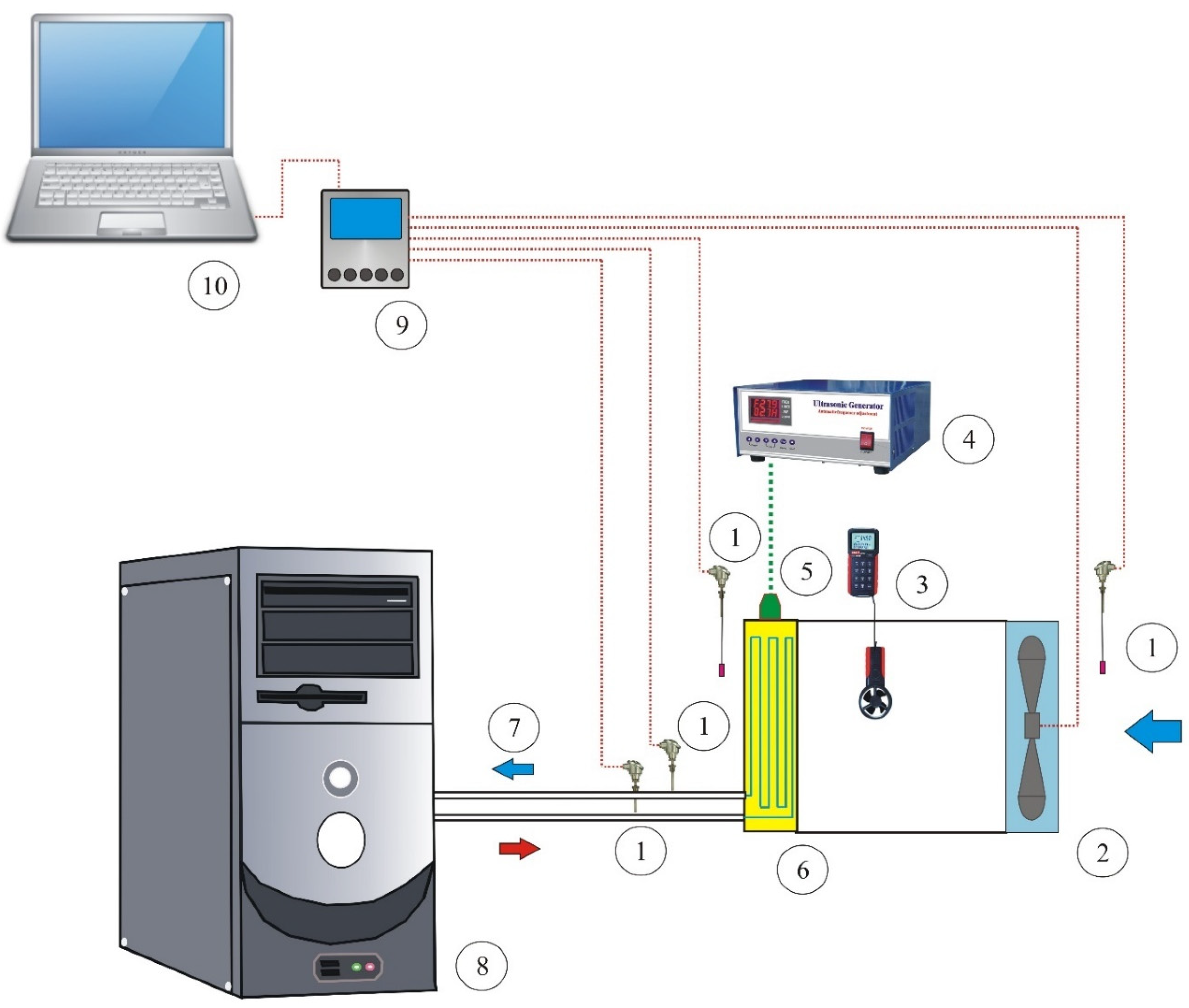
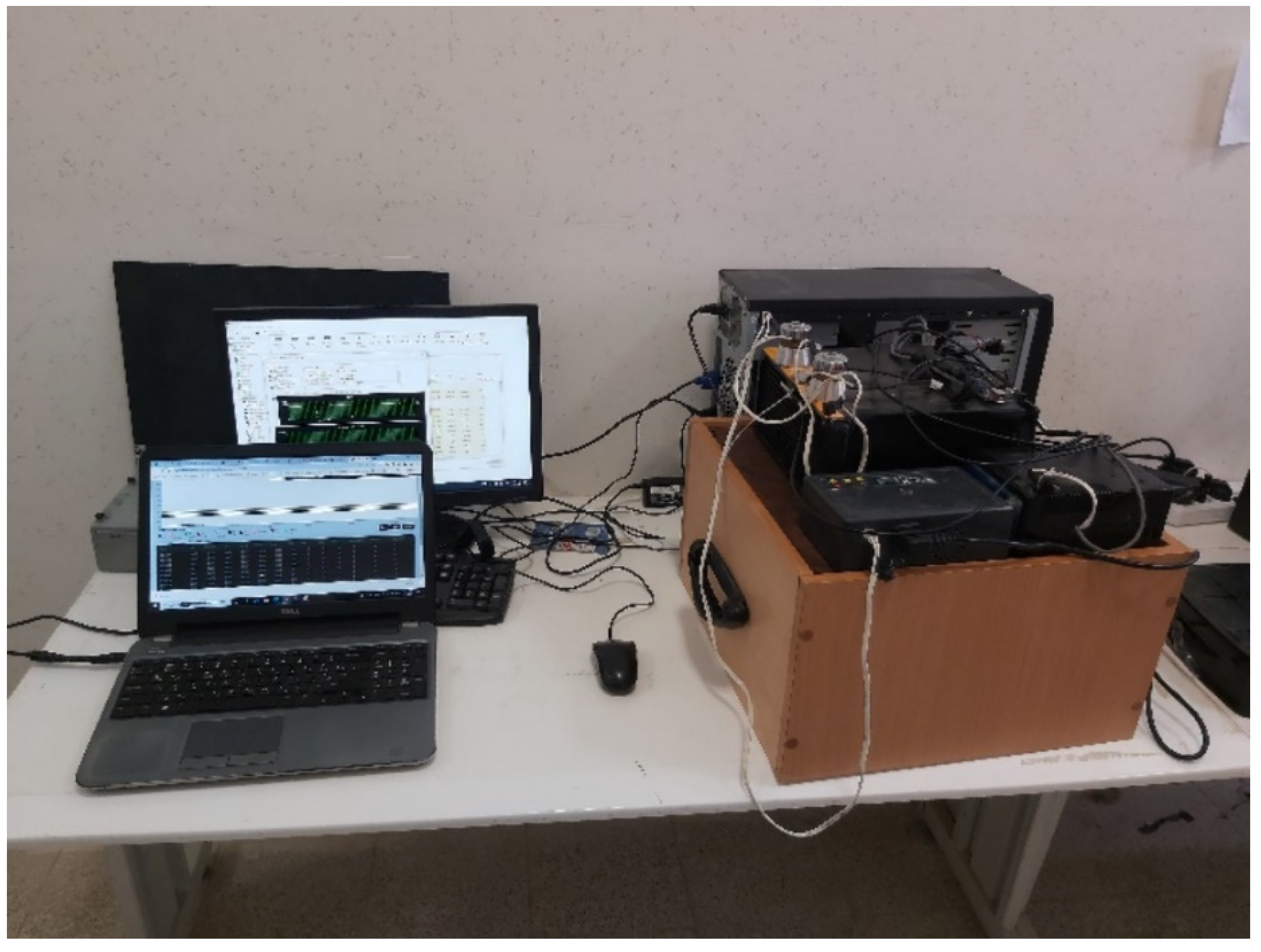
3. Experimental Apparatus

In this section, the experimental setup and the experiment method are discussed in detail. Figure 2 presents the schematic of the experimental setup and its different parts. Furthermore, a picture of the laboratory equipment is shown in Figure 3. Accordingly, the experimental setup consisted of a test section, a data acquisition system, and an ultrasonic vibration system.
The test section consisted of a CPU (type: Intel(R) Core (TM) i3-6100 CPU @ 3.70 GHz 3.70 GHz) that was cooled by a liquid cooling system. The liquid cooling system in question was a closed liquid circulation system in which water was circulated by a pump (type: 9-pole electro motor) between the CPU and the system radiator. The radiator was made of aluminum with 274 × 120 × 27 mm dimensions. The heat transfer process between the CPU and water was conducted by a microchannel copper base. In addition, the heat transferred to the water in the radiator part was transferred to the outside air, which was moved by two fans (fan airflow rate: 2 × 87.5 CFM max; fan speed: 2200 RPM max). In these tests, there was the ability to control the fan speed between 0 and 100. A short rectangular tunnel was constructed between the radiator and the fans to prevent the fan control system from being disrupted by the ultrasonic vibrations. The speed of air movement in the experiment was measured by a flowmeter. Four temperature sensors (type: Maxim Integrated Co., USA, Model: DS18B20; range: −55 to +155 °C; accuracy: ±0.5 °C) were used to measure the water temperature at the inlet and outlet of the radiator as well as the air temperature before and after passing over the radiator. To apply the ultrasonic vibration, two ultrasonic piezoelectric transducers (type: Hesentec Ultrasonic Co., model: HS-8SH-3840) with a frequency of 40 kHz were installed on the top of the radiator. These transducers were connected to an ultrasonic generator, and their power could be set to 30 or 60 watts. A unique data acquisition and control system was designed for this setup. This system could control the power of the ultrasonic transducers and record the data from the temperature sensors. In addition, this system could wirelessly send the information to the laptop to avoid the noises produced by the ultrasonic vibrations. It was necessary to put the CPU in the worst possible state in terms of heat generation to complete the test. For this purpose, Aida 64 software was used, and the CPU performance was set to 100% and fixed. First, the values were recorded for the state where no ultrasonic vibration was applied, and then the results were obtained for different ultrasonic powers of 30, 60, and 120 watts. At each stage, the system ran for some time and reached a steady state. To analyze the obtained data, we acted as follows. First, the temperature difference between the wall temperature (Tw) and the bulk temperature of the fluid flow inside the radiator tube was calculated by one of the following two methods. The mean temperature method was calculated as follows [32,33]:
Δ T b u l k = ( T i + T o 2 ) T w ,
where T i and T o are the inlet and outlet temperatures of the working fluid, respectively. In addition, T w is the wall temperature of the radiator. The log mean temperature difference (LMTD) method was calculated as follows [32,33]:
Δ T b u l k = T i T o L n ( T i T w T o T w )
Then, the convection heat transfer coefficient was calculated from the following equation:
h = q A Δ T b u l k
where A is the area of the heat transfer surface. In addition, the heat transfer rate (q) was calculated from the following equation:
q = m ˙ c p ( T i T o )
In Equation (4), m · represents the mass flux, and Cp represents the specific heat capacity. The fluid temperatures at the inlet and outlet of the radiator tube are indicated by Ti and To, respectively. In addition, the dimensionless Nusselt number for the flow inside the radiator tube is as follows:
N u = h D k
In Equation (5), k is the thermal conductivity, and d is the tube diameter.

4. Uncertainty Analysis

Experimental uncertainty analysis is an important parameter in the interpretation of empirical validation-based results. The procedure introduced by Moffat [34] is used to check the uncertainty of the experimental tests. If the dependent parameter Ω is considered a function of independent parameters ( γ 1 , γ 2 ,…, γ n ), then the uncertainty formula is as follows [34]:
δ Ω = i = 1 n [ ( Ω γ i   δ γ i ) 2 ] 0.5 , Ω = Ω ( γ 1 ,   γ 2 ,   ,   γ n )
where δΩ is the dependent parameter’s uncertainty. In addition, δ γ 1 , δ γ 2 , …, δ γ n are the independent parameters’ uncertainty. For the current tests, the uncertainties of the performance parameters calculated based on Equation (6) are presented in Table 1.

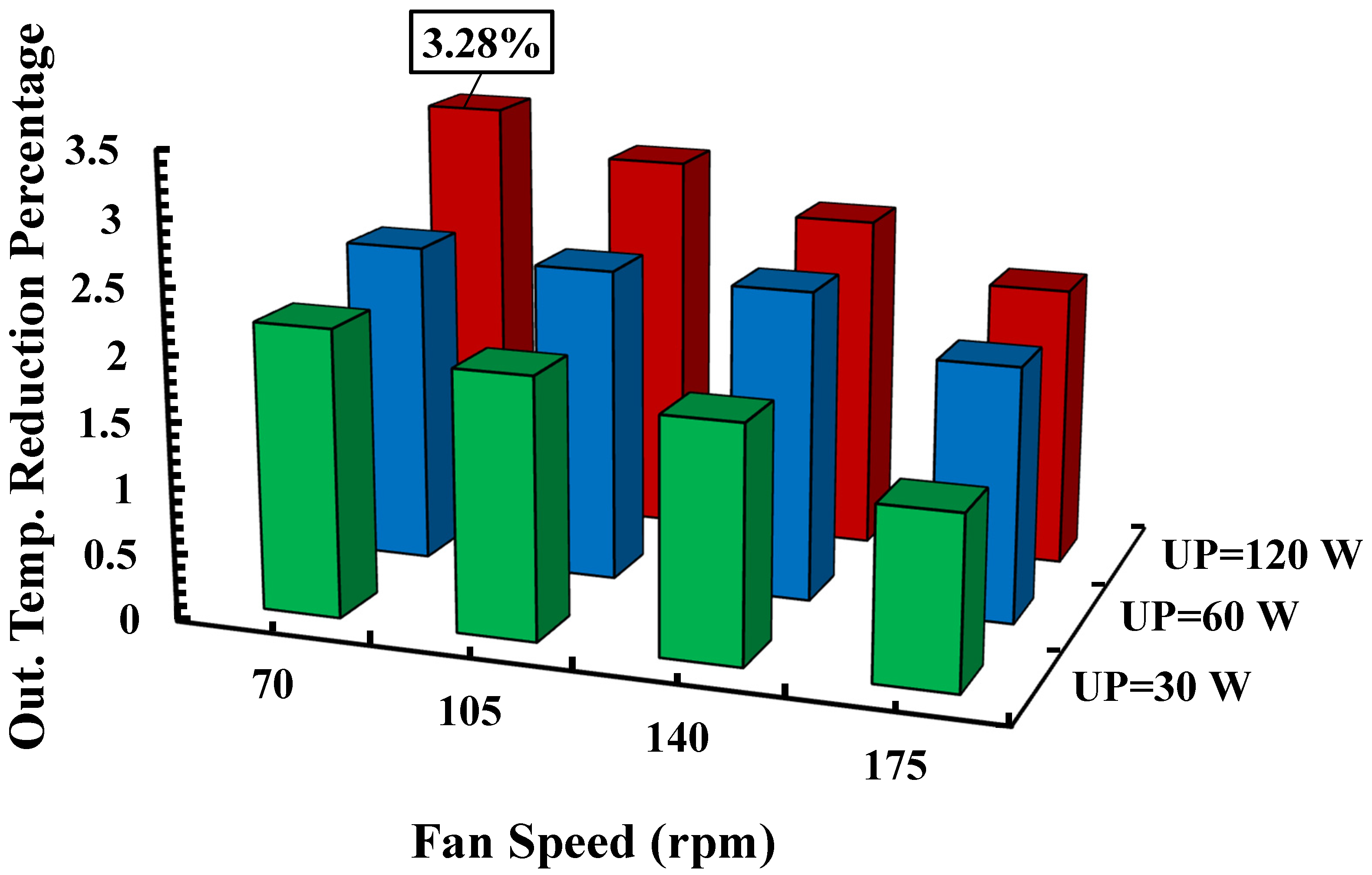
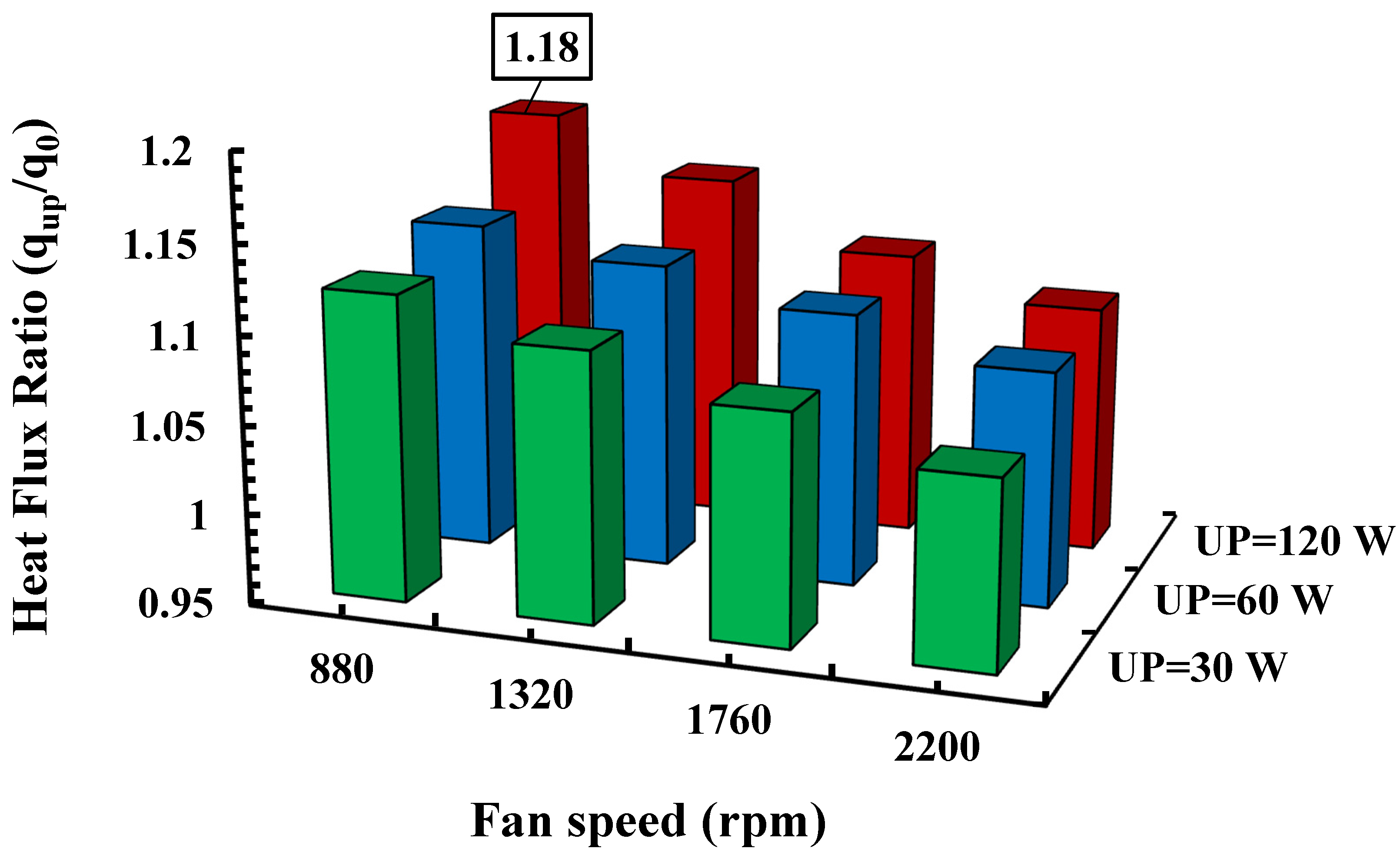
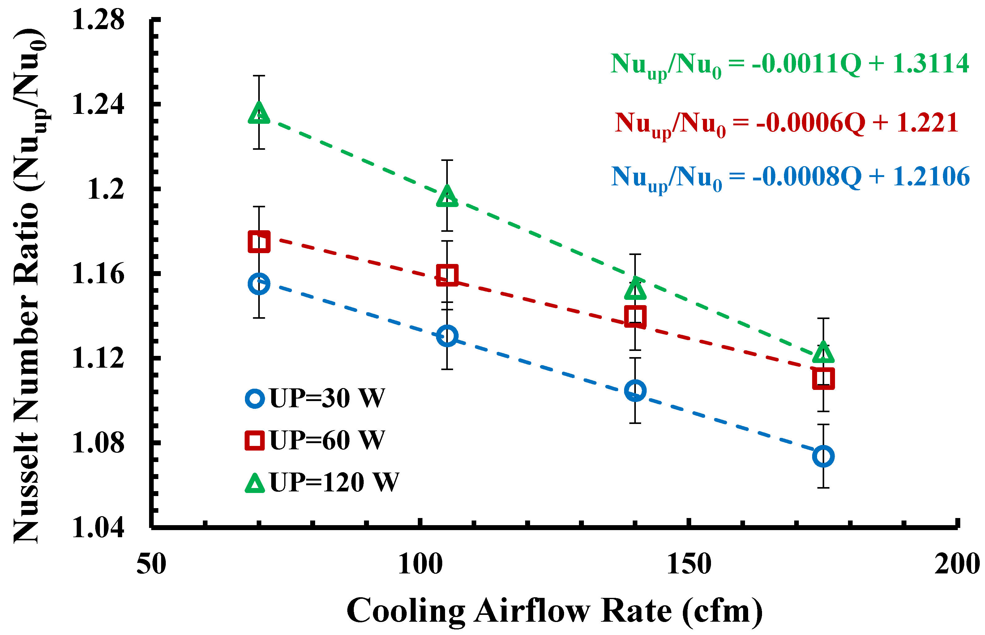
5. Result and Discussion

In this section, the data validation was conducted first, and then the results of the tests in two modes of silence and with the presence of ultrasonic vibrations in different powers were reported. In the present experiments, the Reynolds number (Re) and Prandtl number (Pr) were 3265 and 6.45, respectively. The flow regime inside the radiator tube was turbulent. So, the famous Gnielinski correlation [35], which is presented for 3000 ≤ Re ≤ 5 × 10⁶ and 0.5 ≤ Pr ≤ 2000, was used to validate the present results:
N u = ( f 8 ) ( R e 1000 ) P r 1 + 12.7 ( f 8 ) 1 / 2 ( P r 2 / 3 1 )     ,                  
The relation introduced by Petukhov et al. [36] was used to measure the friction coefficient ( f ) used in the Gnielinski relation [35]:
f = ( 0.79 ln R e 1.64 ) 2                     3000     R e     5   ×   10 6
In Figure 4, the results of the mean temperature (Equation (1)) and the LMTD (Equation (2)) methods are compared with the values obtained from the Gnielinski correlation [35]. As seen in this figure, both the mean temperature and the LMTD methods had enough accuracy for an experimental study. The outlet temperature reduction percentage with respect to the fan speed in the different ultrasonic power levels is presented in Figure 5. Regarding this figure, the ultrasonic vibration led to a temperature reduction in all the cases and improved the thermal performance of the CPU cooler. As discussed in Section 2, ultrasonic wave propagation in a liquid medium inside radiator tubes leads to several phenomena such as micro-streaming, micro-turbulence, shock wave, and convective thermal resistance reduction in the boundary layer. These phenomena were introduced as the leading causes of heat transfer improvement in the presence of ultrasonic waves.
In addition, the outlet temperature reduction percentage increased with increasing the ultrasonic power. However, the fan speed had a negative effect on the outlet temperature reduction. The maximum reduction percentage was 3.28%, which happened at the highest ultrasonic power and lowest fan speed levels. The ultrasonic power could destroy the hydrodynamic and thermal boundary layer both inside and outside of the radiator tube. The effect of boundary layer distributions was more visible when the flow speed over the boundary was lower (which happened at lower aeration volumes of the fans).
Furthermore, the values of the outlet temperature in the absence of ultrasonic vibrations and also in the presence of ultrasonic vibrations with power levels of 30, 60, and 120 W are shown in Table 2. This table is presented for different fan speeds of 70, 105, 140, and 175 RPM.
Figure 6 shows the variation in the heat flux ratio (qup/q0) with different values of the fan speed and ultrasonic power (UP) levels. Regarding this figure, the effects of ultrasonic vibrations were highlighted with lower fan speeds and higher ultrasonic power levels. The graphs show that the most significant increase in the heat transfer ratio of 1.18 occurred at a power level of 120 W and a fan speed of 880 rpm.
The convection coefficient ratio in terms of ultrasonic power and fan speed level is presented in Figure 7 for both the mean temperature and LMTD methods. The presence of ultrasonic waves increased the heat transfer coefficient, especially at lower fan speeds and higher ultrasonic powers. Figure 8 is related to the variation in the Nusselt number ratio in terms of the cooling airflow rate (Q). Figure 8 is presented for the different ultrasonic power levels of 30, 60, and 120 watts. As expected, the variation trend in the Nusselt number ratio with increasing the ultrasonic power was similar to the convection heat transfer coefficient. In addition, the ratio of the Nusselt number decreased with the increase in the cooling airflow, which was equivalent to the increase in the fan speed. An interesting point regarding the variation trend in the Nusselt number ratio in relation to cooling airflow was its linear changes. The equation of the corresponding lines is shown in Figure 8 for the different ultrasonic power levels.

6. Conclusions

In this study, the heat transfer improvement of liquid computer coolers using ultrasonic vibration technology was investigated. For this purpose, appropriate laboratory equipment was made, and the accuracy of the measurements was evaluated by existing empirical correlations. In addition, the phenomenon of acoustic cavitation was extensively discussed as one of the essential factors introduced in the heat transfer enhancement of the present system. Experiments were performed with three different cooling airflow rates and ultrasonic power levels of 30, 60, and 120 watts. The CPU was placed in its maximum performance mode, which had the highest heat generation, to evaluate the thermal parameters in the absence and presence of ultrasonic vibrations. The results showed that applying ultrasonic vibrations increased the heat transfer and improved the thermal performance of the CPU cooling system. In addition, the effects of ultrasonic vibrations were enhanced by increasing the ultrasonic power and reducing the cooling airflow rate. The best impact of the ultrasonic vibrations occurred at the highest ultrasonic power and the lowest aeration volume of the cooling fans. The highest value of the heat transfer ratio (qup/q0) and Nusselt number ratio (Nuup/Nu0) were 1.18 and 1.24, respectively. The technology of continuously applying ultrasonic vibrations, along with the advantage of increasing heat transfer, can pave the way for the practical use of nanofluids in computer cooling systems due to their anti-fouling and anti-agglomeration properties.

Author Contributions

Conceptualization, A.A.D.; methodology, formal Analysis, A.A.D.; validation, H.S.; investigation, H.S. and G.A.; methodology H.S. and G.A.; supervision, G.A.; writing—original draft, A.A.D. All authors have read and agreed to the published version of the manuscript.

Funding

This work has been supported by the Center for International Scientific Studies & Collaborations (CISSC), Ministry of Science Research and Technology, Iran [grant number: 1025].

Data Availability Statement

Data are available upon request to the corresponding author.

Acknowledgments

The authors sincerely thank the editors and the reviewers for their valuable comments and suggestions, which greatly improve the quality of this article.

Conflicts of Interest

All authors declare that they have no conflict of interest.

References

  1. Sohel Murshed, S.M.; Nieto de Castro, C.A. A critical review of traditional and emerging techniques and fluids for electronics cooling. Renew. Sustain. Energy Rev. 2017, 78, 821–833. [Google Scholar] [CrossRef]
  2. Agostini, B.; Fabbri, M.; Park, J.E.; Wojtan, L.; Thome, J.R.; Michel, B. State of the Art of High Heat Flux Cooling Technologies. Heat Transf. Eng. 2007, 28, 258–281. [Google Scholar] [CrossRef]
  3. Pedram, M.; Nazarian, S. Thermal Modeling, Analysis, and Management in VLSI Circuits: Principles and Methods. Proc. IEEE 2006, 94, 1487–1501. [Google Scholar] [CrossRef] [Green Version]
  4. Zhang, N.; Du, Y. Ultrasonic enhancement on heat transfer of palmitic-stearic acid as PCM in unit by experimental study. Sustain. Cities Soc. 2018, 43, 532–537. [Google Scholar] [CrossRef]
  5. Yaralioglu, G. Ultrasonic heating and temperature measurement in microfluidic channels. Sens. Actuators A Phys. 2011, 170, 1–7. [Google Scholar] [CrossRef]
  6. Gibbons, J.; Houghton, G. Effects of sonic vibrations on boiling. Chem. Eng. Sci. 1961, 15, 146–148. [Google Scholar] [CrossRef]
  7. Larson, M.B. A Study of the Effects of Ultrasonic Vibrations on Convective Heat Transfer in Liquids. Ph.D. Thesis, Stanford University, Stanford, CA, USA, 1961. [Google Scholar]
  8. Bergles, A.E.; Newell, J.P. The influence of ultrasonic vibrations on heat transfer to water flowing in annuli. Int. J. Heat Mass Transf. 1965, 8, 1273–1280. [Google Scholar] [CrossRef]
  9. Oh, Y.K.; Park, S.H.; Cho, Y.I. A study of the effect of ultrasonic vibrations on phase-change heat transfer. Int. J. Heat Mass Transf. 2002, 45, 4631–4641. [Google Scholar] [CrossRef]
  10. Nomura, S.Y. Ultrasonic Heat Transfer Enhancement Using a Horn-Type Transducer. Jpn. J. Appl. Phys. 2002, 41, 3217–3222. [Google Scholar] [CrossRef]
  11. Gondrexon, N.; Rousselet, Y.; Legay, M.; Boldo, P.; Le Person, S.; Bontemps, A. Intensification of heat transfer process: Improvement of shell-and-tube heat exchanger performances by means of ultrasound. Chem. Eng. Process. Process Intensif. 2010, 49, 936–942. [Google Scholar] [CrossRef]
  12. Yao, Y.; Zhang, X.; Guo, Y. Experimental study on heat transfer enhancement of water-water shell-and-tube heat exchanger assisted by power ultrasonic. In Proceedings of the 13th International Refrigeration and Air-Conditioning Conference at Purdue, West Lafayette, IN, USA, 12–15 July 2010. [Google Scholar]
  13. Legay, M.; Simony, B.; Boldo, P.; Gondrexon, N.; Le Person, S.; Bontemps, A. Improvement of heat transfer by means of ultrasound: Application to a double-tube heat exchanger. Ultrason. Sonochem. 2011, 19, 1194–1200. [Google Scholar] [CrossRef] [PubMed]
  14. Legay, M.; Le Person, S.; Gondrexon, N.; Boldo, P.; Bontemps, A. Performances of two heat exchangers assisted by ultrasound. Appl. Therm. Eng. 2012, 37, 60–66. [Google Scholar] [CrossRef]
  15. Dhanalakshmi, N.P.; Nagarajan, R.; Sivagaminathan, N.; Prasad, B.V.S.S.S. Acoustic enhancement of heat transfer in furnace tubes. Chem. Eng. Process. Process Intensif. 2012, 59, 36–42. [Google Scholar] [CrossRef]
  16. Gondrexon, N.; Cheze, L.; Jin, Y.; Legay, M.; Tissot, Q.; Hengl, N.; Baup, S.; Boldo, P.; Pignon, F.; Talansier, E. Intensification of heat and mass transfer by ultrasound: Application to heat exchangers and membrane separation processes. Ultrason. Sonochem. 2015, 25, 40–50. [Google Scholar] [CrossRef]
  17. Tam, H.K.; Tam, L.M.; Ghajar, A.J.; Chen, I.P. Experimental study of the ultrasonic effect on heat transfer inside a horizontal mini-tube in the laminar region. Appl. Therm. Eng. 2017, 114, 1300–1308. [Google Scholar] [CrossRef]
  18. Chen, S.W.; Liu, F.C.; Lin, H.J.; Ruan, P.S.; Su, Y.T.; Weng, Y.C.; Wang, J.R.; Lee, J.D.; Lin, W.K. Experimental test and empirical correlation development for heat transfer enhancement under ultrasonic vibration. Appl. Therm. Eng. 2018, 143, 639–649. [Google Scholar] [CrossRef]
  19. Delouei, A.A.; Sajjadi, H.; Mohebbi, R.; Izadi, M. Experimental study on inlet turbulent flow under ultrasonic vibration: Pressure drop and heat transfer enhancement. Ultrason. Sonochem. 2019, 51, 151–159. [Google Scholar] [CrossRef]
  20. Delouei, A.A.; Sajjadi, H.; Izadi, M.; Mohebbi, R. The simultaneous effects of nanoparticles and ultrasonic vibration on inlet turbulent flow: An experimental study. Appl. Therm. Eng. 2019, 146, 268–277. [Google Scholar] [CrossRef]
  21. Bulliard-Sauret, O.; Berindei, J.; Ferrouillat, S.; Vignal, L.; Memponteil, A.; Poncet, C.; Leveque, J.M.; Gondrexon, N. Heat transfer in-tensification by low or high frequency ultrasound: Thermal and hydrodynamic phenomenological analysis. Exp. Therm. Fluid Sci. 2019, 104, 258–271. [Google Scholar] [CrossRef]
  22. Bulliard-Sauret, O.; Ferrouillat, S.; Vignal, L.; Memponteil, A.; Gondrexon, N. Heat transfer enhancement using 2 MHz ultrasound. Ultrason. Sonochem. 2017, 39, 262–271. [Google Scholar] [CrossRef]
  23. Setareh, M.; Saffar-Avval, M.; Abdullah, A. Experimental and numerical study on heat transfer enhancement using ultrasonic vi-bration in a double-pipe heat exchanger. App. Therm. Eng. 2019, 159, 113867. [Google Scholar] [CrossRef]
  24. Setareh, M.; Saffar-Avval, M.; Abdullah, A. Heat transfer enhancement in an annulus under ultrasound field: A numerical and experimental study. Int. Commun. Heat Mass Transf. 2020, 114, 104560. [Google Scholar] [CrossRef]
  25. Zhang, Y.; Abatzoglou, N. Review: Fundamentals, applications and potentials of ultrasound-assisted drying. Chem. Eng. Res. Des. 2020, 154, 21–46. [Google Scholar] [CrossRef]
  26. Dehbani, M.; Rahimi, M.; Rahimi, Z. A review on convective heat transfer enhancement using ultrasound. Appl. Therm. Eng. 2022, 208, 118273. [Google Scholar] [CrossRef]
  27. Legay, M.; Gondrexon, N.; Le Person, S.; Boldo, P.; Bontemps, A. Enhancement of Heat Transfer by Ultrasound: Review and Recent Advances. Int. J. Chem. Eng. 2011, 2011, 670108. [Google Scholar] [CrossRef]
  28. Manasseh, R. Acoustic Bubbles, Acoustic Streaming, and Cavitation Microstreaming. In Handbook of Ultrasonics and Sonochemistry; Springer: Berlin/Heidelberg, Germany, 2016; pp. 33–68. [Google Scholar]
  29. Kuppa, R.; Moholkar, V.S. Physical features of ultrasound-enhanced heterogeneous permanganate oxidation. Ultrason. Sonochem. 2010, 17, 123–131. [Google Scholar] [CrossRef]
  30. Pecha, R.; Gompf, B. Microimplosions: Cavitation Collapse and Shock Wave Emission on a Nanosecond Time Scale. Phys. Rev. Lett. 2000, 84, 1328–1330. [Google Scholar] [CrossRef]
  31. Neppiras, E.A. Acoustic cavitation. Phys. Rep. 1980, 61, 159–251. [Google Scholar] [CrossRef]
  32. Nazari, M.; Ashouri, M.; Kayhani, M.H.; Tamayol, A. Experimental study of convective heat transfer of a nanofluid through a pipe filled with metal foam. Int. J. Therm. Sci. 2015, 88, 33–39. [Google Scholar] [CrossRef]
  33. Delouei, A.A.; Atashafrooz, M.; Sajjadi, H.; Karimnejad, S. The thermal effects of multi-walled carbon nanotube concentration on an ultrasonic vibrating finned tube heat exchanger. Int. Commun. Heat Mass Transf. 2022, 135, 106098. [Google Scholar] [CrossRef]
  34. Moffat, R.J. Describing the uncertainties in experimental results. Exp. Therm. Fluid Sci. 1988, 1, 3–17. [Google Scholar] [CrossRef]
  35. Gnielinski, V. New Equations for Heat and Mass Transfer in Turbulent Pipe and Channel Flow. Int. Chem. Eng. 1976, 16, 359–368. [Google Scholar]
  36. Petukhov, B.S. Advances in Heat Transfer; Irvine, T.F., Hartnett, J.P., Eds.; Academic Press: New York, NY, USA, 1970; Volume 6. [Google Scholar]
Figure 1. Prediction of maximum heat flux and power of microprocessor chips [1]. Predictions show that the rate of heat flux generation in microprocessors is increasing rapidly.
Water 14 04000 g001
Figure 2. Schematic of laboratory equipment. 1: Temperature sensor; 2: cooling fan; 3: airflow meter; 4: ultrasonic generator; 5: ultrasonic transducer; 6: radiator; 7: water tubes; 8: computer processor; 9: control unit; 10: laptop.
Water 14 04000 g002
Figure 3. Overview of laboratory equipment installed in the laboratory.
Water 14 04000 g003
Figure 4. Comparison of the results obtained from the average temperature and LMTD methods with the values obtained from the Gnielinski correlation [35]. The Reynolds and Prandtl numbers were 3265 and 6.46, respectively. Comparing the results showed that both methods used in the present work, i.e., the average temperature method and the LMTD method, had acceptable accuracy.
Water 14 04000 g004
Figure 5. The outlet temperature reduction percentage with different fan speeds and ultrasonic power levels. The outlet temperature was decreased by increasing the ultrasonic power level. The ultrasonic effects were highlighted at lower fan speeds. The maximum error of the data in this figure is ±1.9%. The green, blue, and red colors of the columns are related to ultrasonic power levels of 30, 60, and 120 Watts.
Water 14 04000 g005
Figure 6. Changes in the heat flux ratio with different fan speeds and ultrasonic power levels. The positive effects of ultrasonic vibrations on heat transfer enhancement increased by increasing the ultrasonic power level and decreasing the fan speed. The maximum error of the data in this figure is ±2.1%. The green, blue, and red colors of the columns are related to ultrasonic power levels of 30, 60, and 120 Watts.
Water 14 04000 g006
Figure 7. Changes in the convection coefficient ratio with different values of ultrasonic power levels and fan speeds (FS) obtained by (a) the mean temperature and (b) LMTD methods. Applying ultrasonic vibrations increased the convection coefficient ratio, especially at lower fan speeds and higher ultrasonic powers. The maximum error of the data in this figure is ±2.3%.
Water 14 04000 g007
Figure 8. Changes in the Nusselt number ratio according to the cooling airflow rate at different ultrasonic power levels (UP). The Nusselt number ratio decreased by increasing the cooling airflow rate. Variation in the Nusselt number ratio was a linear function of the cooling airflow rate.
Water 14 04000 g008
Table 1. Uncertainty of performance parameters.
ParameterUncertainty
Heat transfer rate±2.1%
Heat transfer coefficient±2.3%
Nusselt number±2.4%
Table 2. Absolute values of outlet temperature difference in different ultrasonic power levels and fan speeds.
Ultrasonic Power
Level
Fan Speed
(RPM)
Outlet
Temperature (°C)
UP = 07021.20
10520.91
14020.37
17520.21
UP = 30 W7020.74
10520.49
14020.01
17519.95
UP = 60 W7020.68
10520.41
14019.89
17519.82
UP = 120 W7020.51
10520.29
14019.84
17519.77
Publisher’s Note: MDPI stays neutral with regard to jurisdictional claims in published maps and institutional affiliations.

