Article

Experimental and Numerical Analysis of Forced Convection in a Horizontal Tube Partially Filled with a Porous Medium under Local Thermal Equilibrium Conditions

by
Behzad Siavash Amoli
1,
Seyed Soheil Mousavi Ajarostaghi
1,2,*,
Majid Saffar-Avval
3,
Reza Hosseini Abardeh
3 and
Nevzat Akkurt
4,*
1
Department of Mechanical Engineering Department, Babol Noshirvani University of Technology, Babol 47148-71167, Iran
2
Mechanical Engineering Department, Université de Sherbrooke, Sherbrooke, QC J1K 2R1, Canada
3
Department of Mechanical Engineering Department, Amirkabir University of Technology, Tehran 15875-4413, Iran
4
Rare Earth Elements Application and Research Center, Munzur University, Tunceli 62000, Turkey
*
Authors to whom correspondence should be addressed.
Water 2022, 14(23), 3832; https://doi.org/10.3390/w14233832
Submission received: 16 October 2022 / Revised: 16 November 2022 / Accepted: 17 November 2022 / Published: 24 November 2022
(This article belongs to the Special Issue Fluid Dynamics Modeling in Porous Media)

Abstract

:
The objective of the present work is to analyze experimentally and numerically the laminar forced convection flow in a horizontal pipe partially filled with a porous medium under constant heat flux and to study the influence of the eccentricity of the porous medium on the results. In a numerical analysis, the governing equations are solved in three dimensions. To simplify the grid generation and the satisfaction of the boundary conditions, conformal mapping is applied to convert the cross-section of the tube in the fluid domain (space between two eccentric circles) into a rectangle, and the equations are solved in a computational domain in this domain. The Darcy–Brinkman–Forchheimer model is applied to simulate the hydrodynamic behavior of the flow in the porous region. Thermal equilibrium between solid and fluid is assumed for the energy equation. A FORTRAN program was developed to solve the equations using the finite volume method and the SIMPLE algorithm. Velocity profile, pressure drop and average Nusselt number are studied in a wide range of Darcy numbers, thickness of porous mediums and eccentricities. The results show that the eccentricity of the porous material reduces the heat transfer coefficient and the pressure drop simultaneously; of course, the reduction in the heat transfer coefficient is less noticeable when the thickness of the porous medium is smaller. For example, at RP = 0.5, when the eccentricity of the porous medium increases up to E = 0.4, the average Nusselt number decreases by 66%, and this reduction for a smaller porous thickness decreases to 11%. The maximum pressure drop reduction for Da = 10−5 and E = 0.4 is 25%.

1. Introduction

In the last two decades, convection heat transfer in porous media has been widely studied because it has a wide range of applications in a variety of fields, such as geothermal energy [1], chemical engineering [2], microscale engineering [3,4], etc. Actually, porous media has brought significant changes to heat transfer enhancement [5,6,7].
The effect of applying porous media on the heat transfer rate in turbulent flow has been studied by many researchers [8,9,10]. Mohamad [11] employed porous media between two parallel plates and in tubes for heat transfer enhancement. It was depicted that a tube partially filled with porous media brings a higher heat transfer rate and lower pressure drop compared to a tube fully filled and saturated with a porous medium. The optimum thickness was obtained at a fixed Darcy number, which resulted in a maximum heat transfer rate.
Pavel and Mohmmad [12] experimentally and numerically studied the convection heat transfer enhancement in a tube partially and fully filled with a porous medium in the range of 1000 to 4500 Reynolds numbers. They concluded that, in both laminar and turbulent flow, the partially filled tube has further heat transfer enhancement and a lower pressure drop. Huang et al. [13] numerically investigated turbulent flow through a heat exchanger, which was filled with a porous medium, and studied the influence of Darcy and Reynolds numbers on heat transfer enhancement. They indicated that the increase in Darcy and Reynolds numbers leads to an increased Nusselt number.
Local thermal equilibrium (LTE) and local thermal non-equilibrium (LTNE) are two different attitudes towards energy equation analysis in porous media, which stand for the local thermal equilibrium and local thermal non-equilibrium of the solid and fluid phase. These two methods have attracted the attention of many researchers, who have studied the effect of a porous medium insert on the heat transfer coefficient in a channel partially filled with the porous medium [14,15,16,17,18,19]. The physics of the solid–fluid boundary condition plays a key role in the LTNE method, while there are no differences between the boundary condition of the solid and fluid phases under LTE conditions. Some works have been conducted that consider both LTNE and LTE methods [16,17]. Torabi et al. [20] modeled force convection in a channel partially filled with a porous medium in the existence of internal heat through both LTNE and LTE approaches. The governing equations were solved and the velocity and temperature fields were compared for both models. They found that the differences in the Nusselt numbers between these two conditions, which increase at a high porous thickness, are non-negligible. The effects of a number of parameters (which include porous media thickness, thermal conductivity ratio and two different positions of porous media) on the quantity and quality of the heat transfer rate have been taken into consideration by Shokouhmand et al. [21]. It is observed that the position of the porous media inside the pipe and the thermal conductivity ratio are two of the factors that most affect the heat transfer rate. Lu et al. [17] utilized the LTNE method to solve the governing equations for a parallel-plate channel partially filled with metallic foams. The results are compared with experimental results for a parallel-plate channel fully filled with metal foam, which are available in other studies. They concluded that a parallel-plate channel completely filled with metal foam experiences a higher pressure drop than partially filled channels. The effects of a wide range of parameters on the heat transfer rate were discussed. It was indicated that the heat transfer rate grows smoother at a higher value of the thermal conductivity ratio [17].
Alkam and Al-Nimr [22] numerically carried out the analysis of an unsteady forced convection in a tube partially filled with a porous medium. They assessed the influence of porous medium thickness, Darcy number and Forchheimer factor on flow properties and found that the time required to reach a steady state increases when the thickness of the porous medium increases to a certain extent, and with a further increase in its thickness, the time taken to reach a steady state reduces. An analysis was conducted by Minkowycz and Haji-Sheikh [23] to determine the hydrodynamically developed and thermally developing flow between parallel plates fully filled with a porous medium. The separation of variables method was employed to solve the energy equation. The temperature field was reported with mathematical series.
Zhao and Song [24] experimentally and analytically studied a forced convection flow inside a porous medium that was under heat flux normal to the flow direction of a permeable wall and obtained a linear relation between Peclet and Nusselt numbers. Alazmi and Vafai [25] considered different transport phenomena models inside a porous medium. They studied models derived from four assumptions, which are constant porosity, variable porosity, thermal dispersion and local thermal non-equilibrium conditions, and concluded that these changes in models are generally more effective in the velocity field than the temperature field.
Shokouhmand et al. [26] evaluated the effect of porous insert position on the enhanced heat transfer in channels partially filled with a porous medium. They simulated a fully developed laminar flow with the Lattice Boltzmann method and concluded that the position of the porous medium in the system has a significant effect on system thermal performance. Haji-Sheikh and Vafai [27] analyzed flow and heat transfer in different-shaped ducts filled with a porous medium using the Brinkman model.
In the present work, the influence of the geometric parameters of the porous media, such as its thickness and eccentricity, were analyzed in the forced convection inside a horizontal tube that is partially filled with a porous medium. Since the porous medium eccentricity disturbs the axial symmetry, a two-dimensional model with an axial symmetry assumption cannot be applied for this problem. Therefore, a three-dimensional model was utilized. In order to access simpler meshing and avoid using complex equations in writing the code of boundary conditions, an analytical conformal mapping was employed to convert the space between two concentric circles (clear fluid region) to a rectangular space. It should be noted that the two-dimensional mapping transforms the cross-section geometry from a physical space to a computational space and the geometry does not change in the axial direction.

2. Materials and Methods

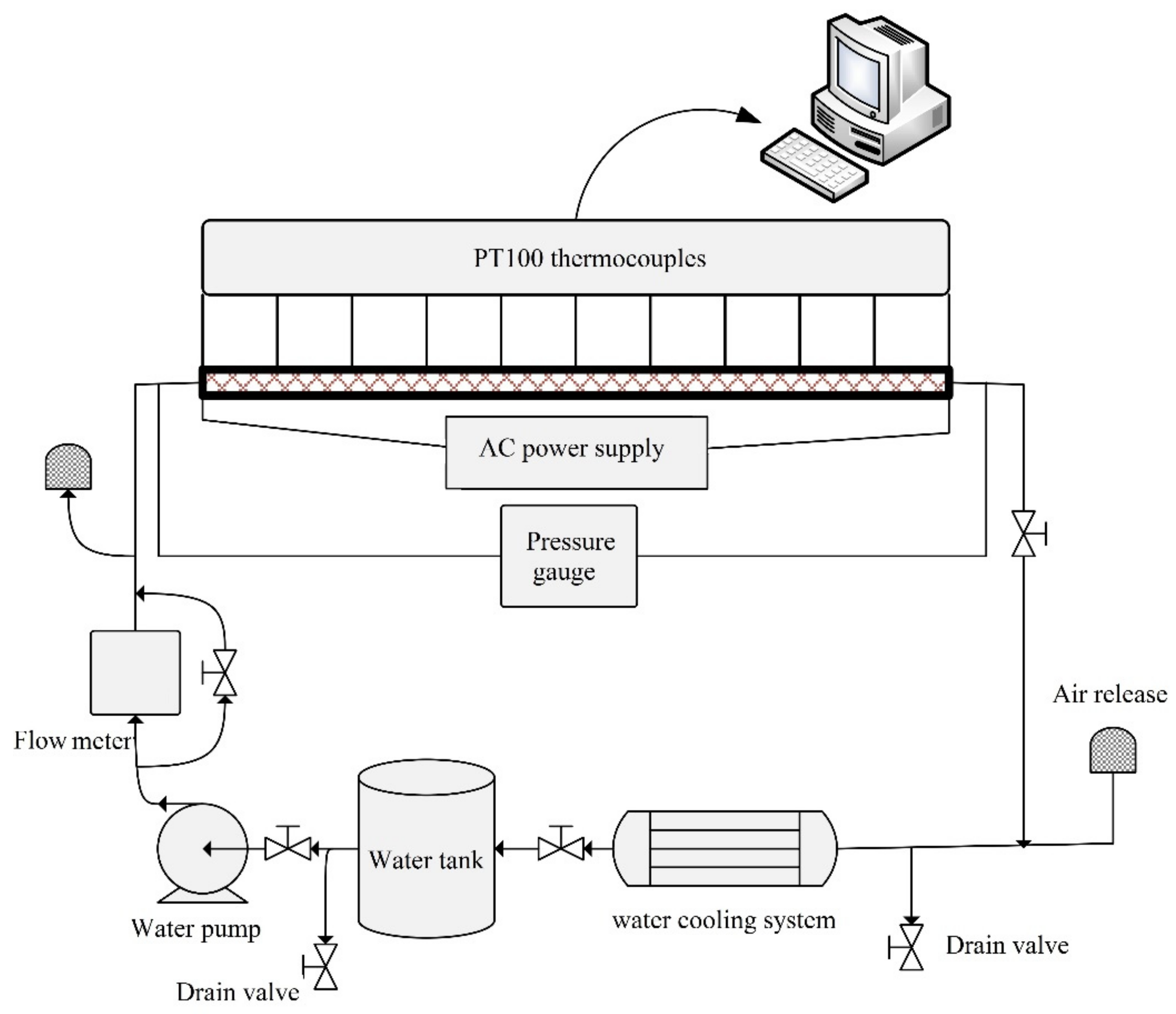
2.1. Experimental Setup

In the experimental setup, as shown in Figure 1, some instrumentation devices were used; their specifications are presented in Table 1. Water as working fluid was pumped into the test section, where an electrical heater element uniformly wrapped the pipe and thick insulation covered the whole pipe. Data from the inlet and outlet temperatures, as well as the wall temperature, were acquired by the thermocouples in order to calculate the HTC. Additionally, a differential pressure (ΔP) gauge measured the pressure drop along the test section in order to compute the friction coefficient along the test section. Copper foam was employed as a porous media with porosity ε = 0.75 and radius ratio r*P = rPorous/r1 = 0.625. Additionally, after the test section, the water as working fluid entered the heat exchanger to reach its initial temperature again. Some properties, such as dynamic viscosity and thermal conductivity, directly used their corresponding experimental measurements.

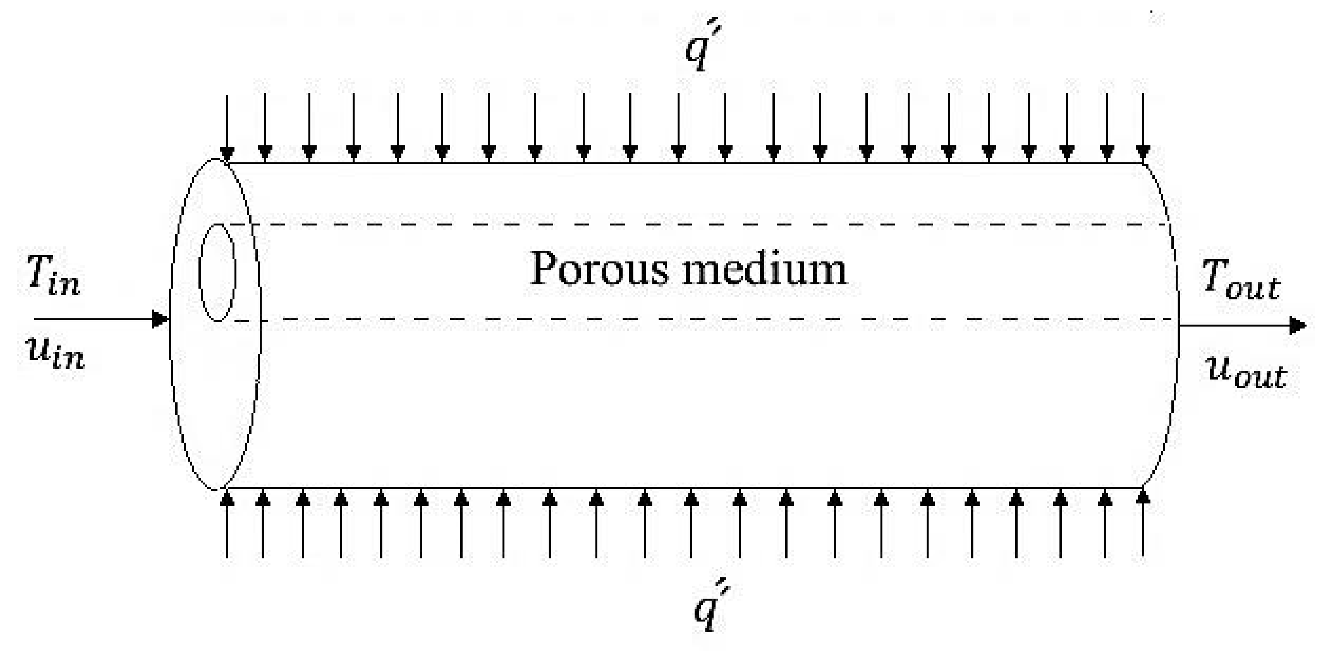
2.2. Governing Equations

The flow is considered laminar, steady, incompressible and three-dimensional. The porous media are supposed to be homogenous and isotropic. Viscous dissipation in energy equation and thermal non-equilibrium between fluid and solid zone in porous media are neglected. Navier–Stokes equations and Darcy–Brinkman–Forchheimer equations are implemented in the clear fluid region and porous region, respectively [31,32]. The geometry of the problem is shown in Figure 2. The non-dimensional parameters used in the governing equations are introduced in Equations (1)–(17).
The non-dimensional governing equations can be written as:
Continuity:
U = u w i n
V = v w i n
W = w w i n
X = x r i
Y = y r i
Z = z r i
E = e r i
T * = T T i n q ´ ´ r i / k e f f
P = p ρ f w i n 2
V d l = V w i n = U 2 + V 2 + W 2
Re = ρ w i n r i μ f
Pr = ν α
Da = K r i 2
R k = k e f f k f
RR = r s r i
Br = μ f w i n 2 q ´ ´ r i
M = μ e f f μ f
U X + V Y + W Z = 0
Momentum:
U U X + U V Y + U W Z = φ 2 P Y + M . φ Re X U X + Y U Y + Z U Z k φ 2 Re . Da U k C F φ 2 Da V d l U
V U X + V V Y + V W Z = φ 2 P Y + M . φ Re X V X + Y V Y + Z V Z k φ 2 Re . Da V k C F φ 2 Da V d l V
W U X + W V Y + W W Z = φ 2 P Y + M . φ Re X W X + Y W Y + Z W Z k φ 2 Re . Da W k C F φ 2 Da V d l W
Energy in fluid zone:
T * U X + T * V Y + T * W Z = R k Re . Pr X T * X + Y T * Y + Z T * Z
Equation (18) is mass balance for an incompressible flow. If k = 0 and φ = 1, the Equations (19)–(21) belong to the clear zone, and if k = 1, it belongs to the porous zone. In Equation (22), Rk is the thermal conductivity ratio that is introduced in Equation (14). For the clear zone, Rk is equal to unity. In Equation (14),   k e f f is the effective thermal conductivity of porous media, which is defined as below:
k e f f = φ k f + 1 φ k s
Boundary conditions of governing equations are defined as follows:
  • Inlet: uniform profile; Z = 0, W = 1, U = V = 0, and T* = 0.
  • Outlet: hydrodynamically and thermally fully development.
a t   Z = l r i :                           U Z = V Z = W Z = 0
a t   Z = l r i :                       T * Z = T s * Z = T m * Z = 2 R k Re . pr . σ
In Equation (25), R k and σ are equal to one for the clear zone. σ is defined as the ratio of thermal capacity, which is evaluated as follows:
σ = φ ρ f C p f + 1 φ ρ s C s ρ f C p f
Wall (at X2 + Y2 = 1):
U = V = W = 0
T * X = R k X
T * Y = R k Y
Equations (28) and (29) are derived from Equations (30)–(33).
at   r = r i   :                 q e r = k f T
a t   x 2 + y 2 = r i 2 :       q cos θ i + q sin θ j = k f T x i + T y j
The sin and cos Cartesian forms are within Equation (31):
q x r i = k f T y
q y r i = k f T y
Non-dimensional forms of Equations (32) and (33) are Equations (28) and (29).
The interface between porous medium (+) and fluid (−) [16] at X E 2 + Y 2 = ( RR ) 2 :
  U + = U
  V + = V
  W + = W
P + = P
T + * = T *
The Equations (34)–(38) specify the interface between porous medium and fluid boundary condition.

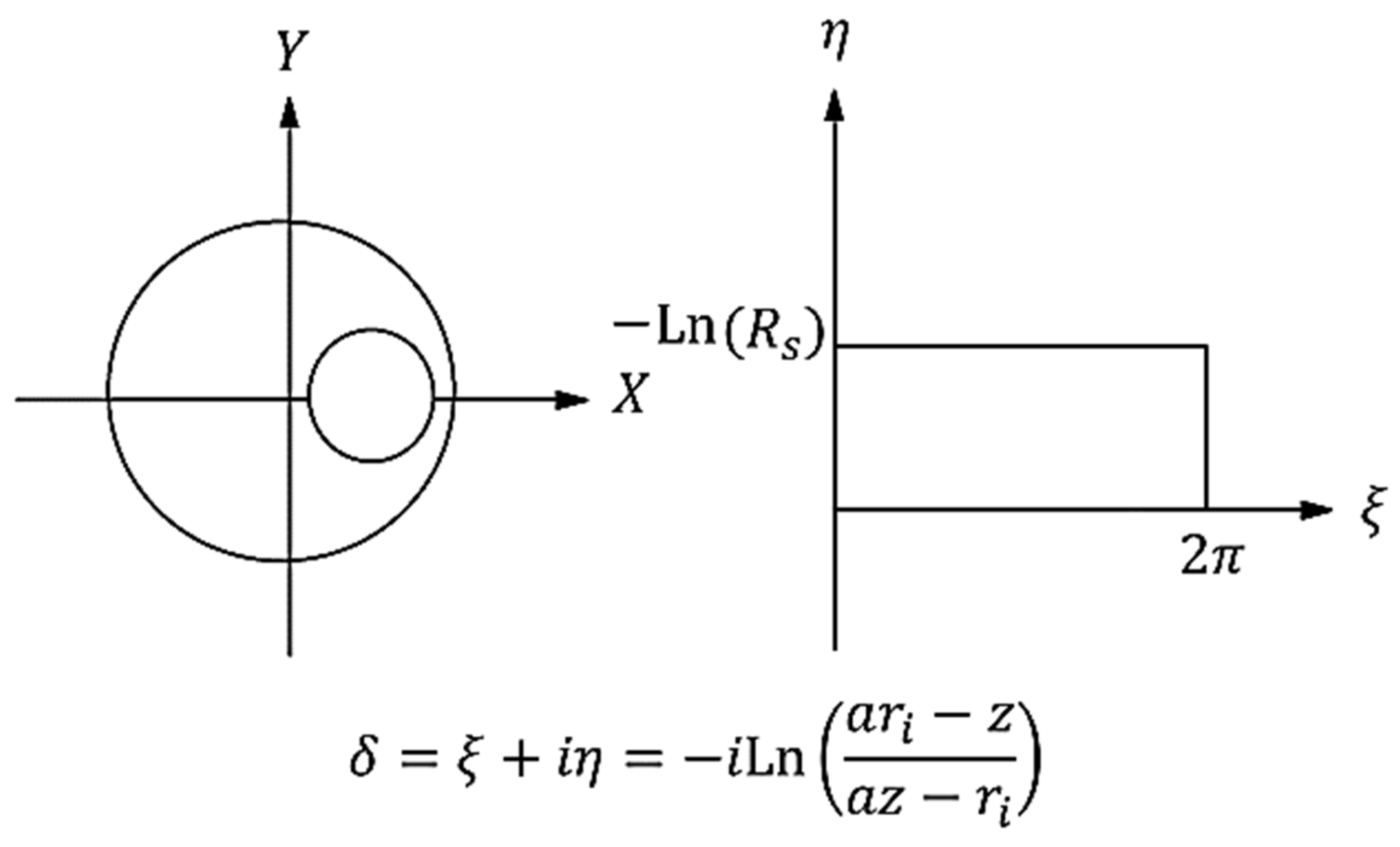
2.2.1. Using Conformal Mapping in Numerical Analysis

In order to simplify grid generation and boundary condition satisfaction, conformal mapping is used to transform the cross-section of the pipe in the clear region to a rectangle, and equations are solved in a computational domain in this region. According to Figure 3, conformal mapping is defined as follows:
ζ + i η = i   Ln a r i Z a Z r i
Required parameters in Equations (19)–(21) and Figure 2 are evaluated in Equations (40) and (41):
a = r i 2 + e 2 r s 2 2 e r i r i 2 + e 2 r s 2 2 e r i 2 1 1 2
R s = e a r i a e a r i 1 2
The transformed conservation equation in the computational domain can be written as Equation (42):
G U * J ξ + G V * J η + G W J Z = Γ G ξ G ξ + η G η + J Z G Z + J S G
Parameters used in the conservation equation in the computational domain are defined as Equations (43)–(47):
Y ξ = 1 a 2 e η cos ξ + a 2 e 2 η cos ξ + 2 a e η 1 + a 2 e 2 η + 2 a e η cos ξ 2
Y η = e η 1 a 2 sin ξ a 2 e 2 η 1 1 + a 2 e 2 η + 2 a e η cos ξ 2
J = Y   ξ 2 + Y η 2
U * = V . Y   ξ + U . Y η J
V * = V . Y η U . Y ξ J
Y ξ and Y η are the metric forms of the physical domain transform into the computational domain.   J is the jacobin, and U * and V *   are defined velocity in the computational domain. The values of G and Γ G and S G are shown in Table 2. In order to evaluate the conservation equation in the computational domain, the Cauchy–Riemann equations used in analytical conformal mapping are applied. The Cauchy–Riemann equations are shown as follows.
X   ξ = Y η
X η = Y   ξ
For the evaluation of the thermo-hydraulic characteristics of the flow in the computational domain, there are several parameters, such as cross-sectional area, average temperature, local Nusselt number and average Nusselt number, which are shown in Equations (50) and (51).
T m * = 0 π 0 1 W T * R . d R . d θ + 0 ln R s 0 π W T * R . d ξ . d η 0 π 0 1 W R . d R . d θ + 0 ln R s 0 π W R . d ξ . d η
To define average temperature, the relevant parameters in any domain of each cross-section should be calculated separately, and then the sum of the parameters is divided by each individual parameter.
Nu X . Y . Z = 2 T s * X . Y . Z T m * Z
Since there is no symmetry in circumferential direction, the outside wall temperature is a function of X, Y and Z. In addition, as it is located on the circle, where there is a relationship between X and Y, one of the variables can be eliminated and Equation (51) may be written in the form of Equation (52):
Nu θ . Z = 2 T s * θ . Z T m * Z
The average Nusselt number can be written as follows:
Nu ave = 0 π 0 L d l Nu θ . Z d Z . d θ 0 π 0 L d l d Z . d θ

2.2.2. Numerical Solution Details

Figure 4 schematically shows domains 1 and 2 in the tube cross-section. Numerical solution of domains 1 and 2 is calculated with two different grids, and the interface between the fluid and porous media is coupled together using boundary condition.

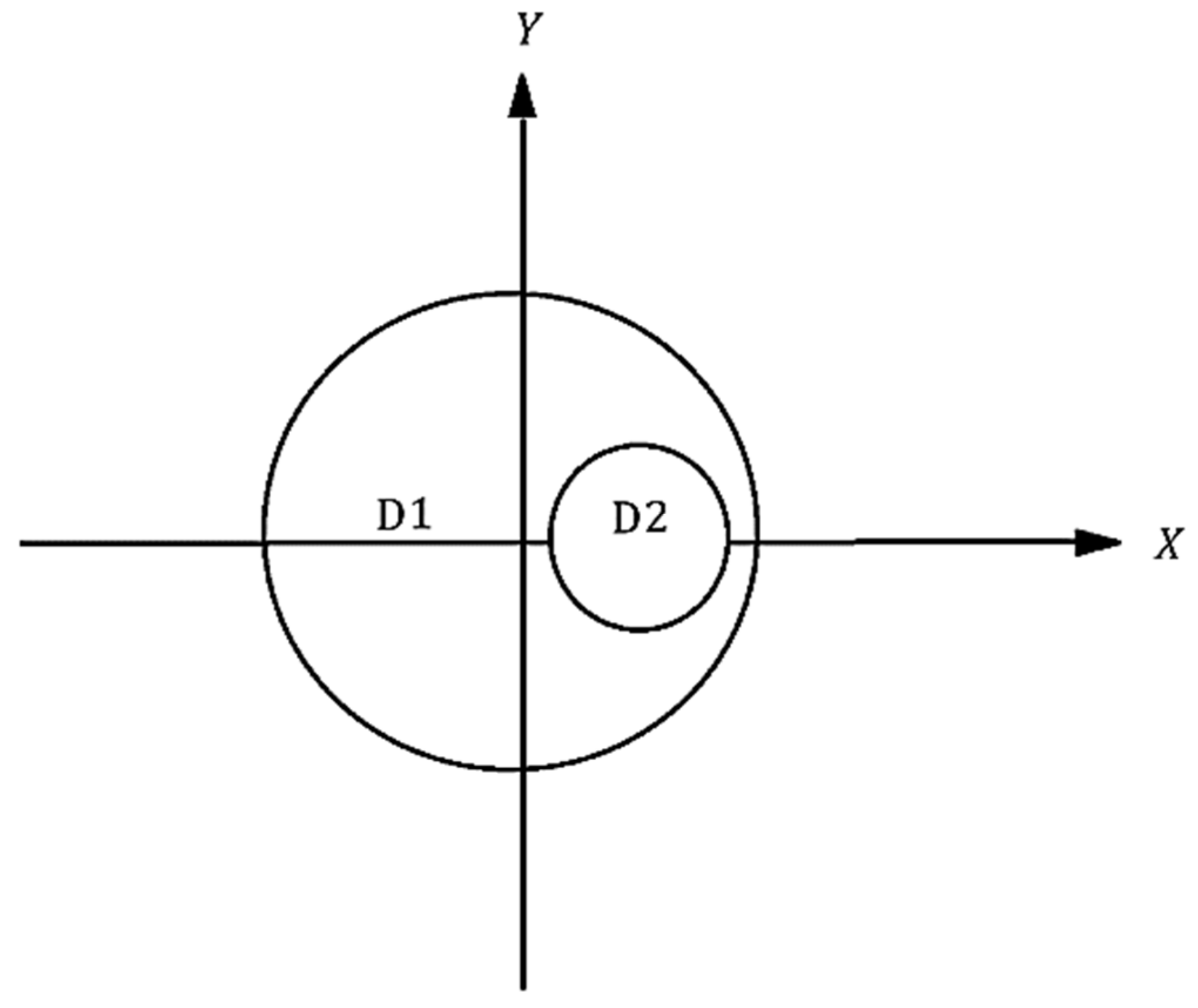
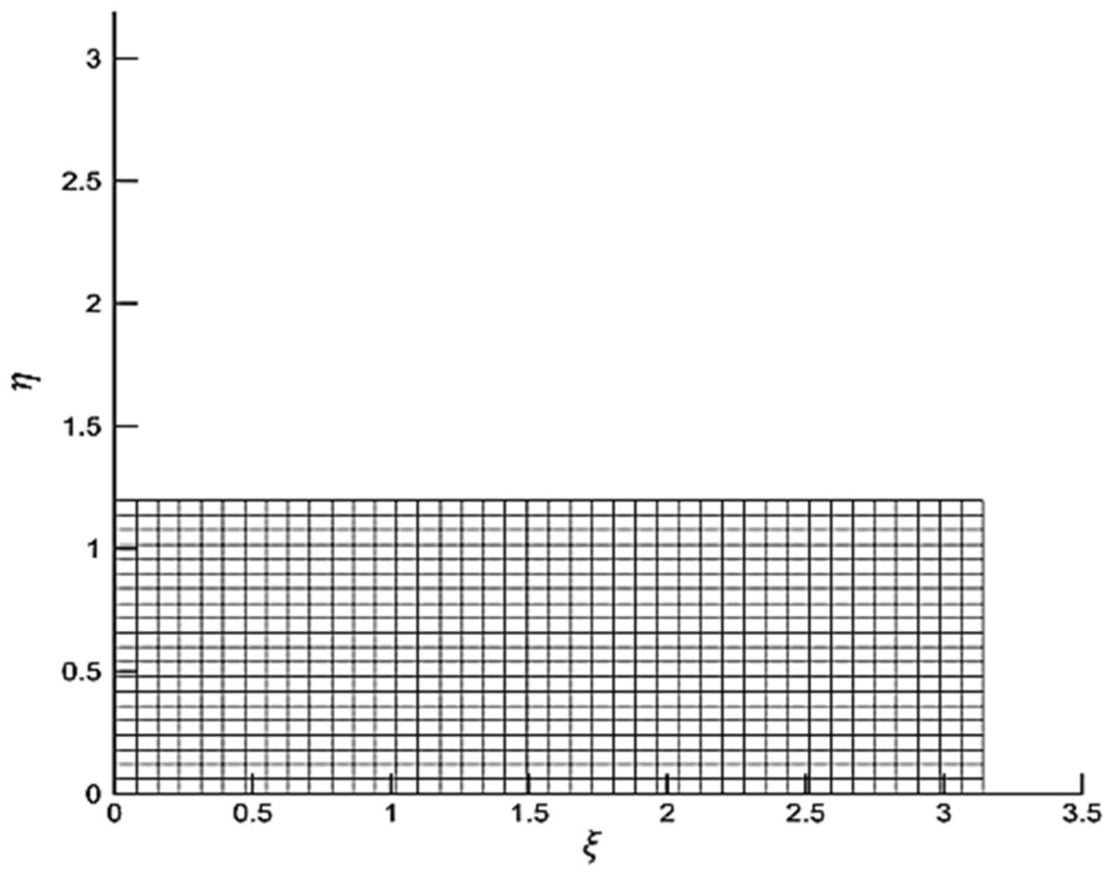
2.2.3. Mesh Domain 1 in Computational Space

When complex mapping is used to convert domain 1, the formed image is rectangular in computational space. According to Figure 5, a structured quadrilateral grid is used for meshing.

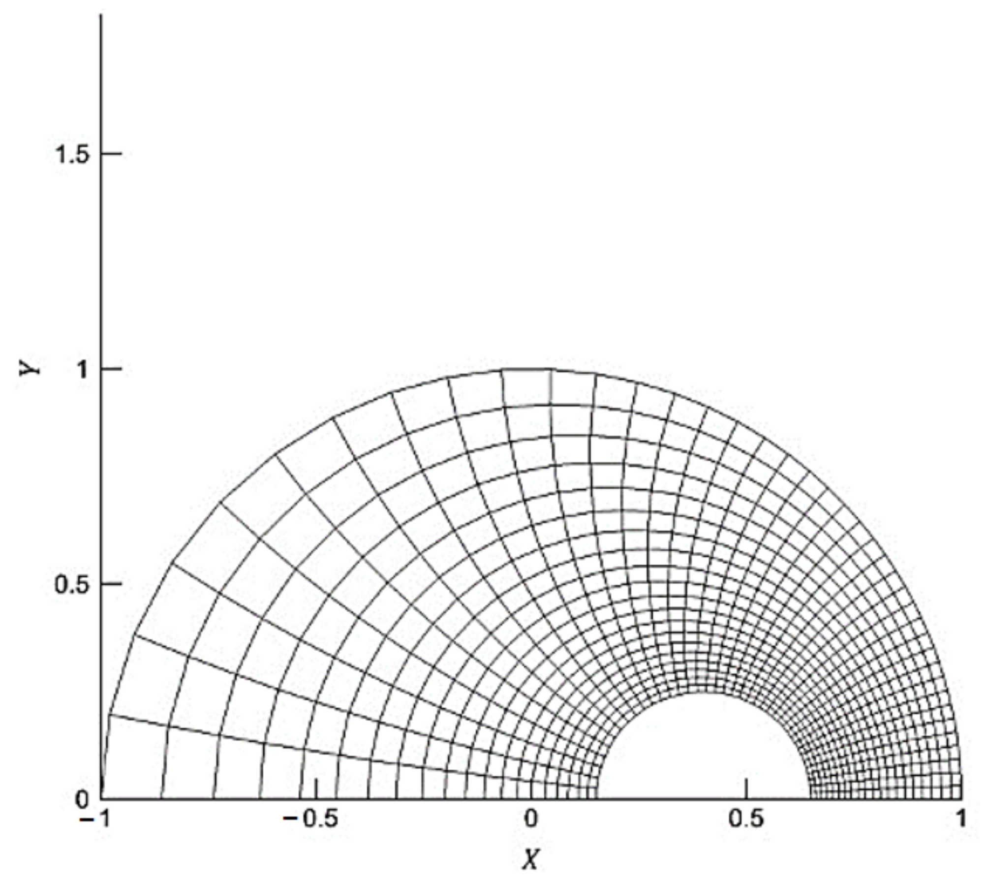
2.2.4. Mesh Domain 1 in Physical Space

Figure 6 shows the generated mesh of domain 1 in a physical space. As can be seen, it is an unstructured grid, which is obtained by applying a reverse mapping on a structure grid.

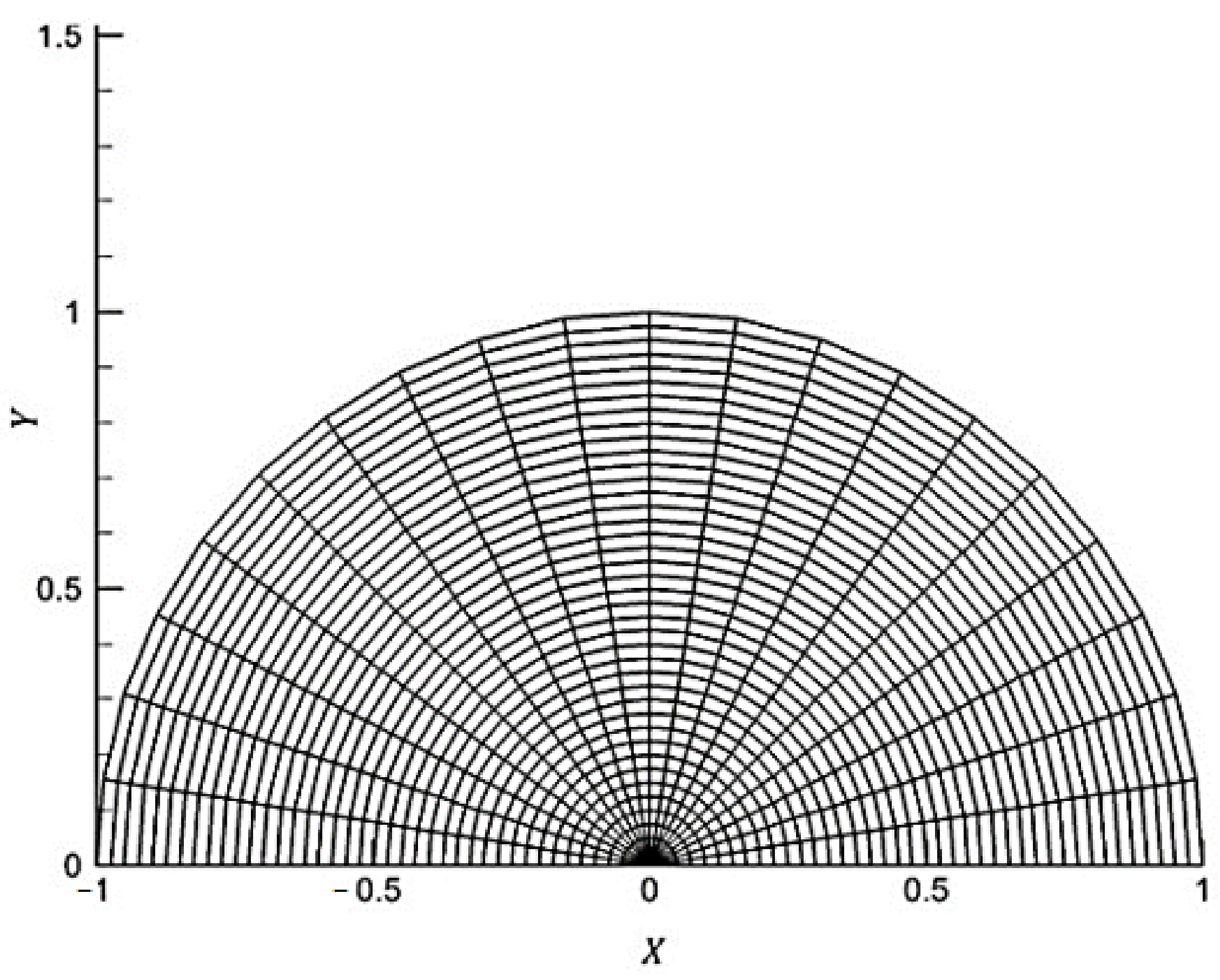
2.2.5. Mesh Domain 2

Cylindrical coordinates are the best coordinates for domain 2. The grid of this domain is shown in Figure 7.

2.2.6. Solution Methodology

With the finite volume method in the converted grid, discrete equations are solved using a simple algorithm. In the converted grid, velocity is considered at the cell boundaries, and temperature and pressure are considered at the center of a cell. Discrete momentum and energy equations are solved using a tridiagonal matrix algorithm that is based on backward elimination and forward substitution. The convergence criterion for the numerical solution is defined as follows:
A P G P A n b G n b S S < 10 3
As the above equation shows the absolute value of differences between total flux of the central point and total flux of neighboring points, as well as the source term for all points in the mesh, the presented convergence criterion is very large. Thus, 0.001 is a reasonable value for the convergence limit.

3. Results and Discussion

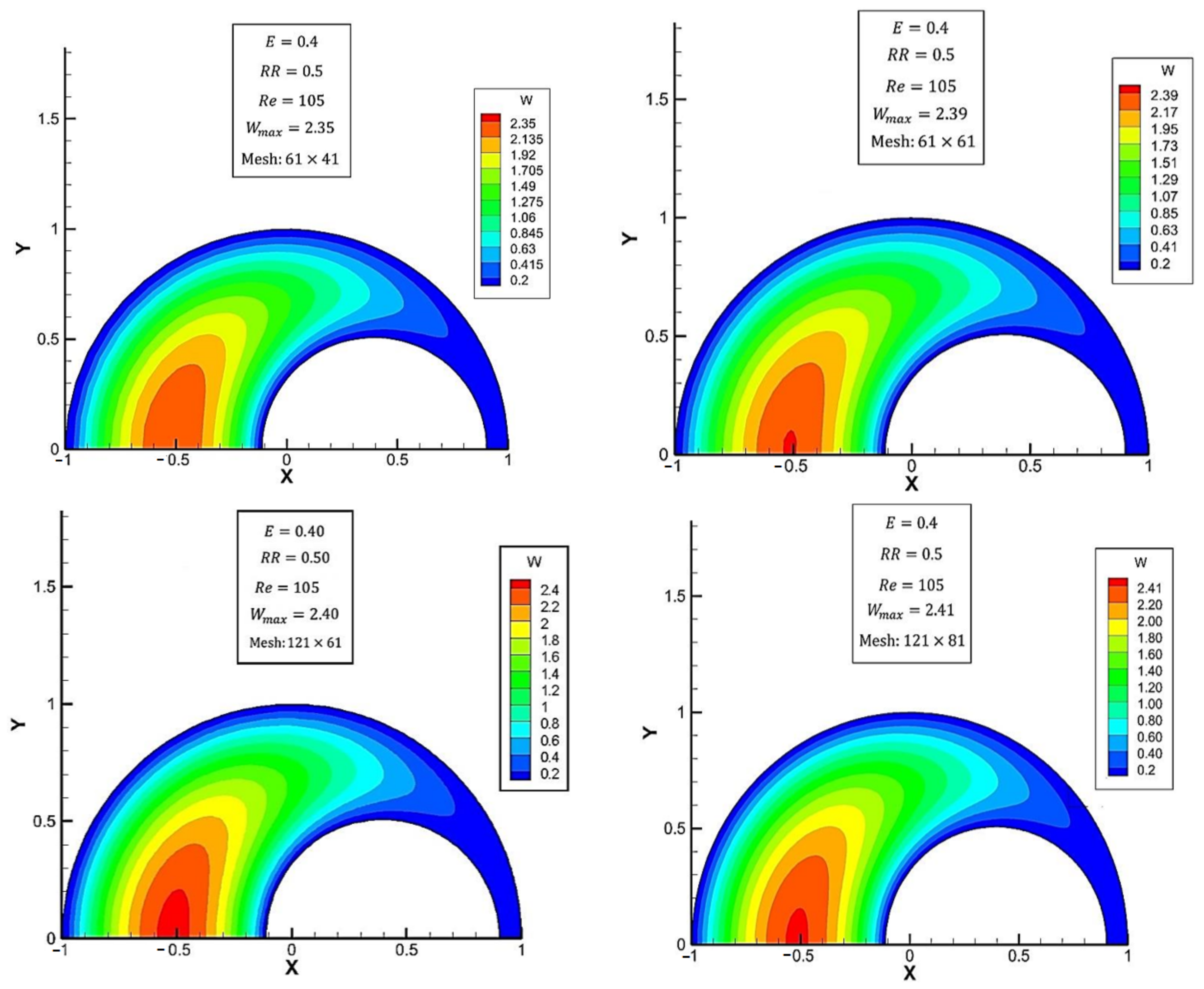
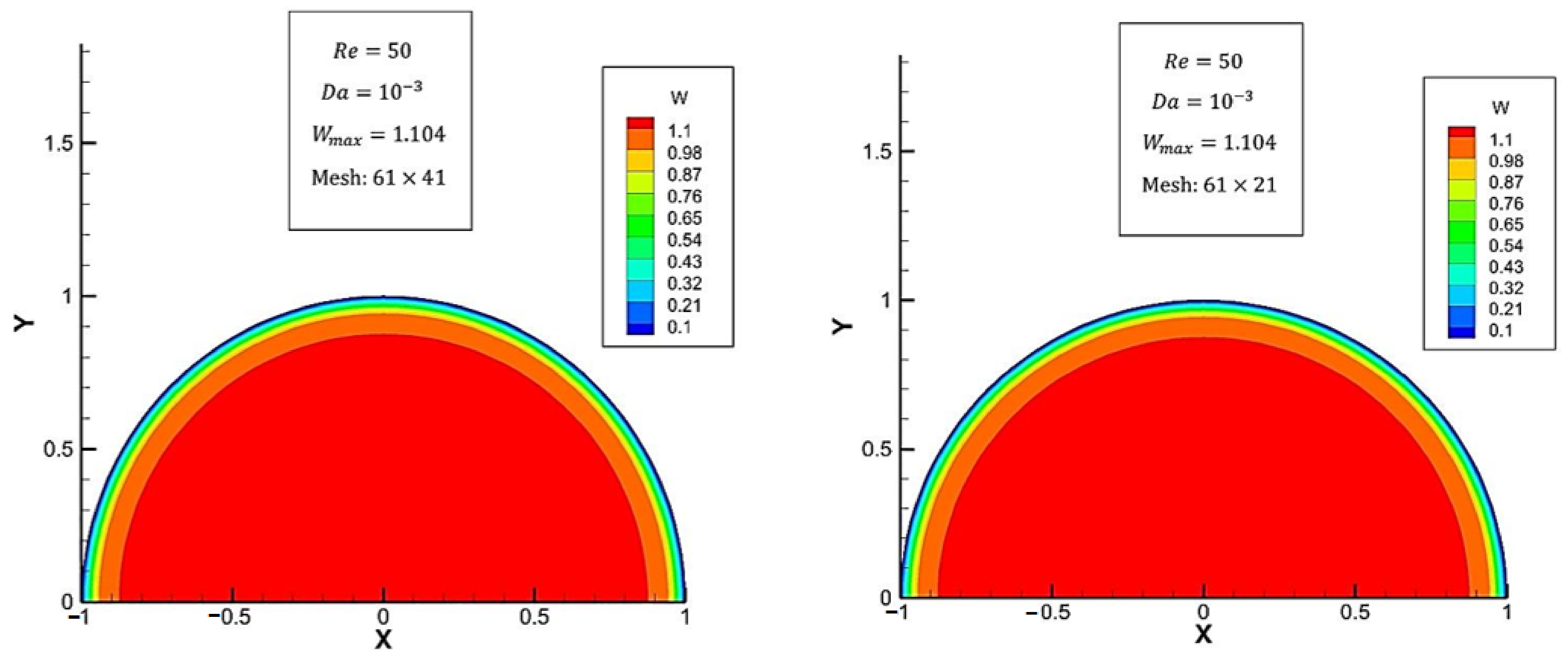
3.1. Grid Independency Analysis

Since in the present study, the solution is performed in two separate domains with two different grids, grid independence should be checked for both meshes. The optimum mesh for each domain is obtained by evaluating the average Nusselt number for the different meshes of domains 1 and 2. As shown in Table 3 and Table 4, the optimum mesh for domains 1 and 2 can be considered as 121 × 61 and 61 × 41 , respectively. For grid in z direction, according to Table 5, the average Nusselt of the total geometry is compared for four different axial meshes. Therefore, the optimum mesh node number in z direction is 130.
Before extracting the results from the numerical solution, the non-dependence of the results from the created grid should be investigated. So, in this work, the solution was made in two different computational domains with two various grids. The mesh independence analysis was carried out for both computational domains. For this purpose, the developed velocity contours and the maximum velocity values for four different grids in domains 1 and 2 are presented in order to obtain the best grid for each of the domains.
The developed velocity contours in the space of two cylinders with various grid numbers are illustrated in Figure 8. Accordingly, it can be seen that the velocity contours for the two cases with 121 × 61 and 121 × 81 grids are similar, and the maximum velocities in these two cases are very close to each other. Therefore, the best grid in the case of space between two eccentric cylinders (domain 1) is 121 × 81.
The same analysis was carried out for the second computational domain: the case of a tube completely filled with a porous medium for two different grids. The developed velocity contours in this case are shown in Figure 9. As can be seen, the fluid flow gives exactly the same answer for the two different grids. Of course, these results were obtained for grids with a larger first component, and there was no difference in the shape of the contours and the maximum velocity; therefore, the best grid in domain 2 (related to the porous area) is considered to be 61 × 41. However, as the peripheral components of the grids in the computational domains 1 and 2 must be equal, we ultimately applied the 121 × 41 grid.

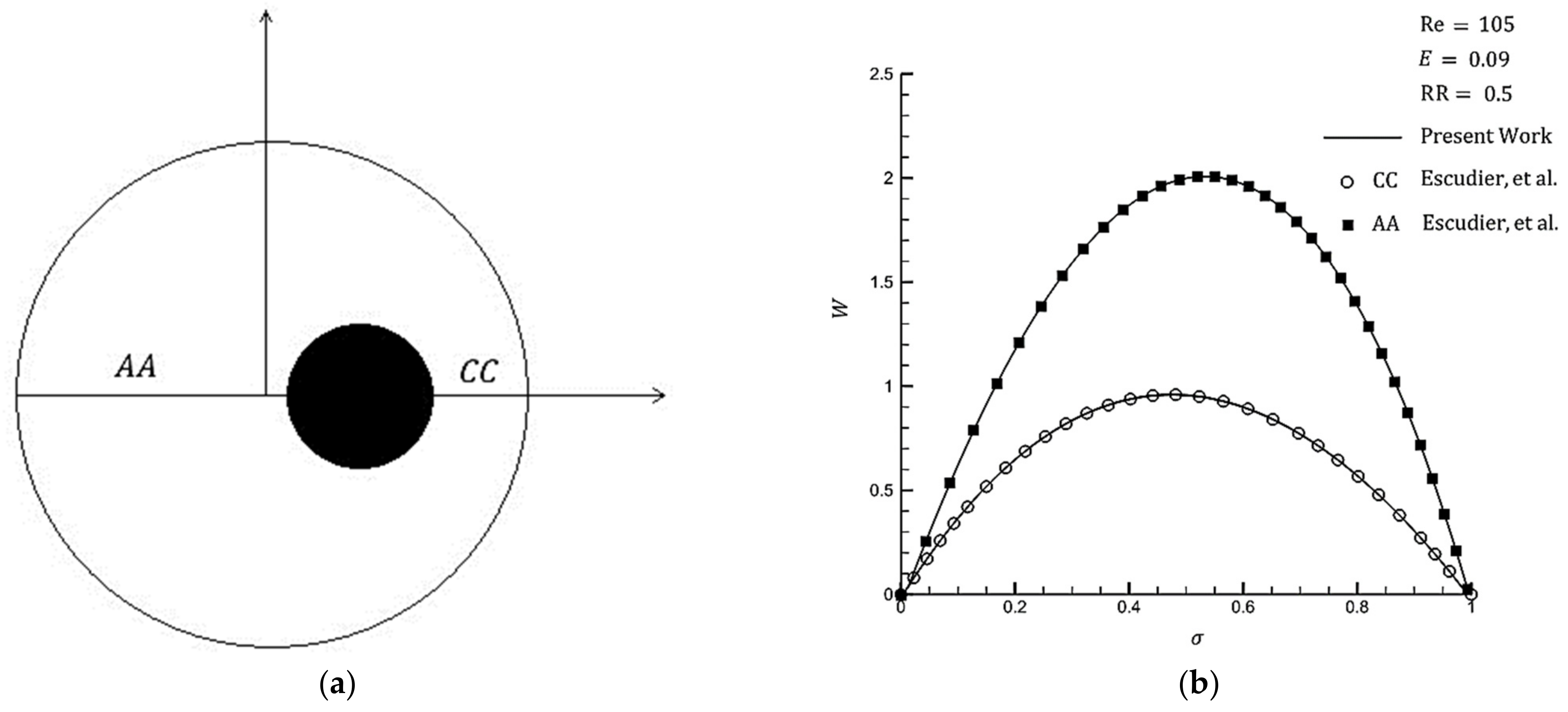
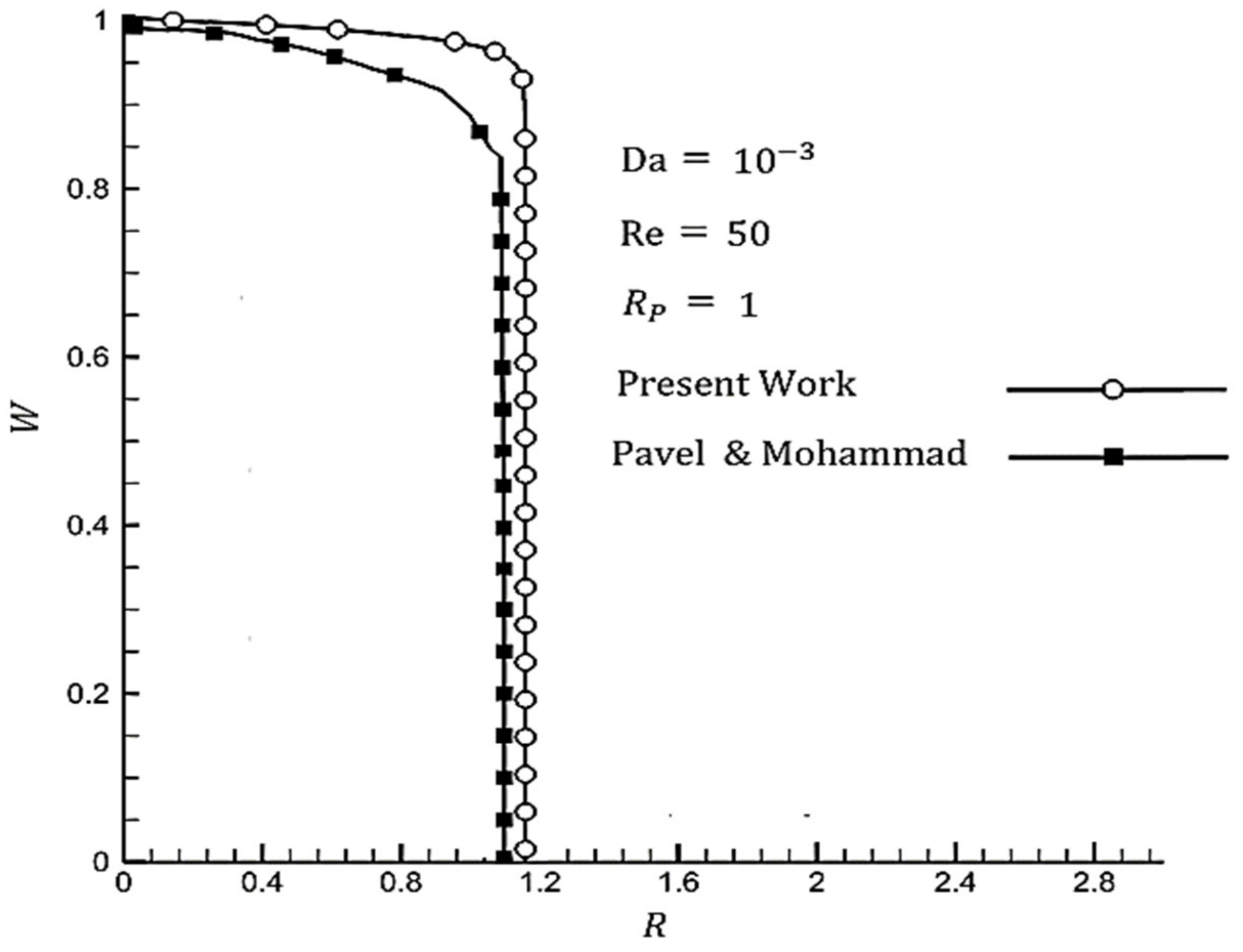
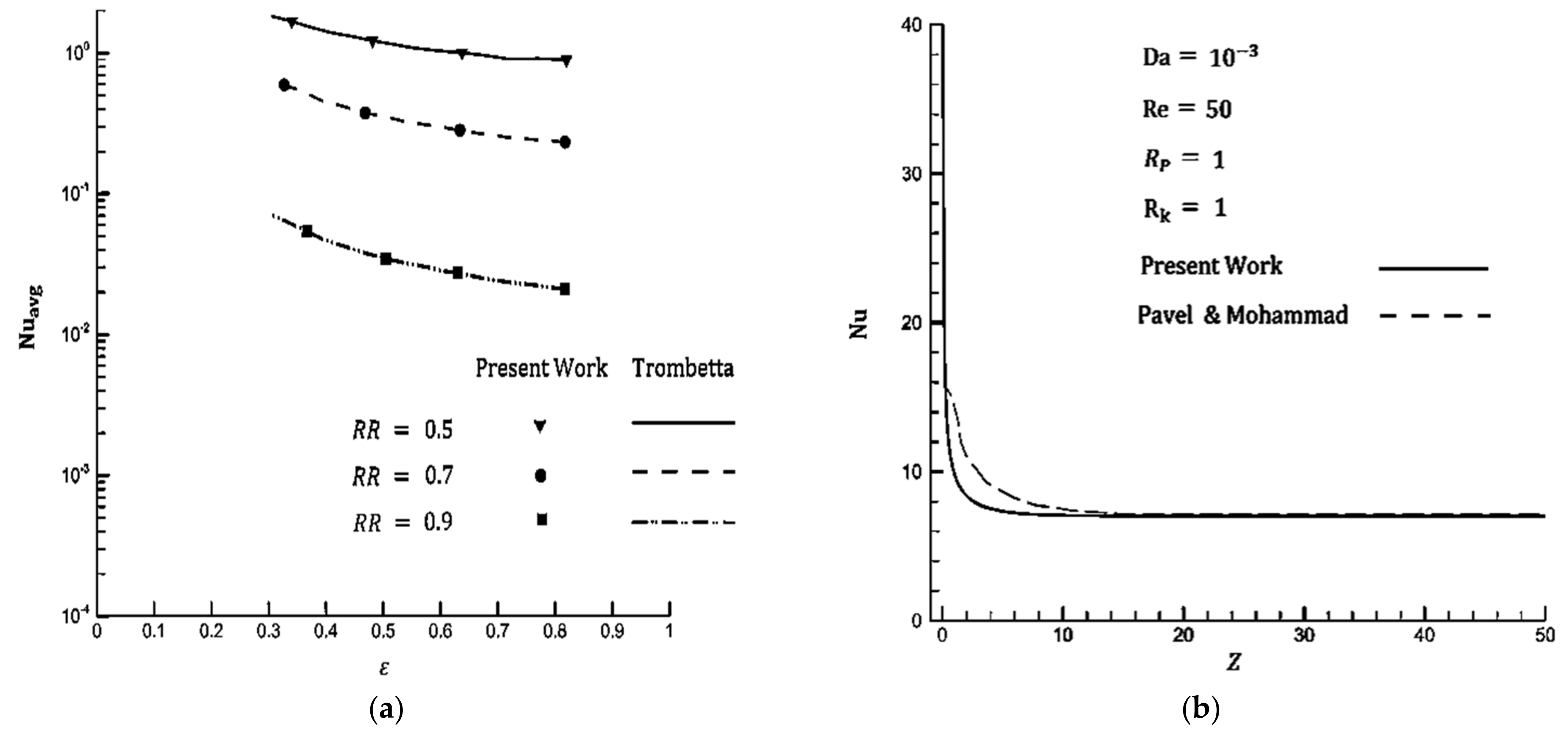
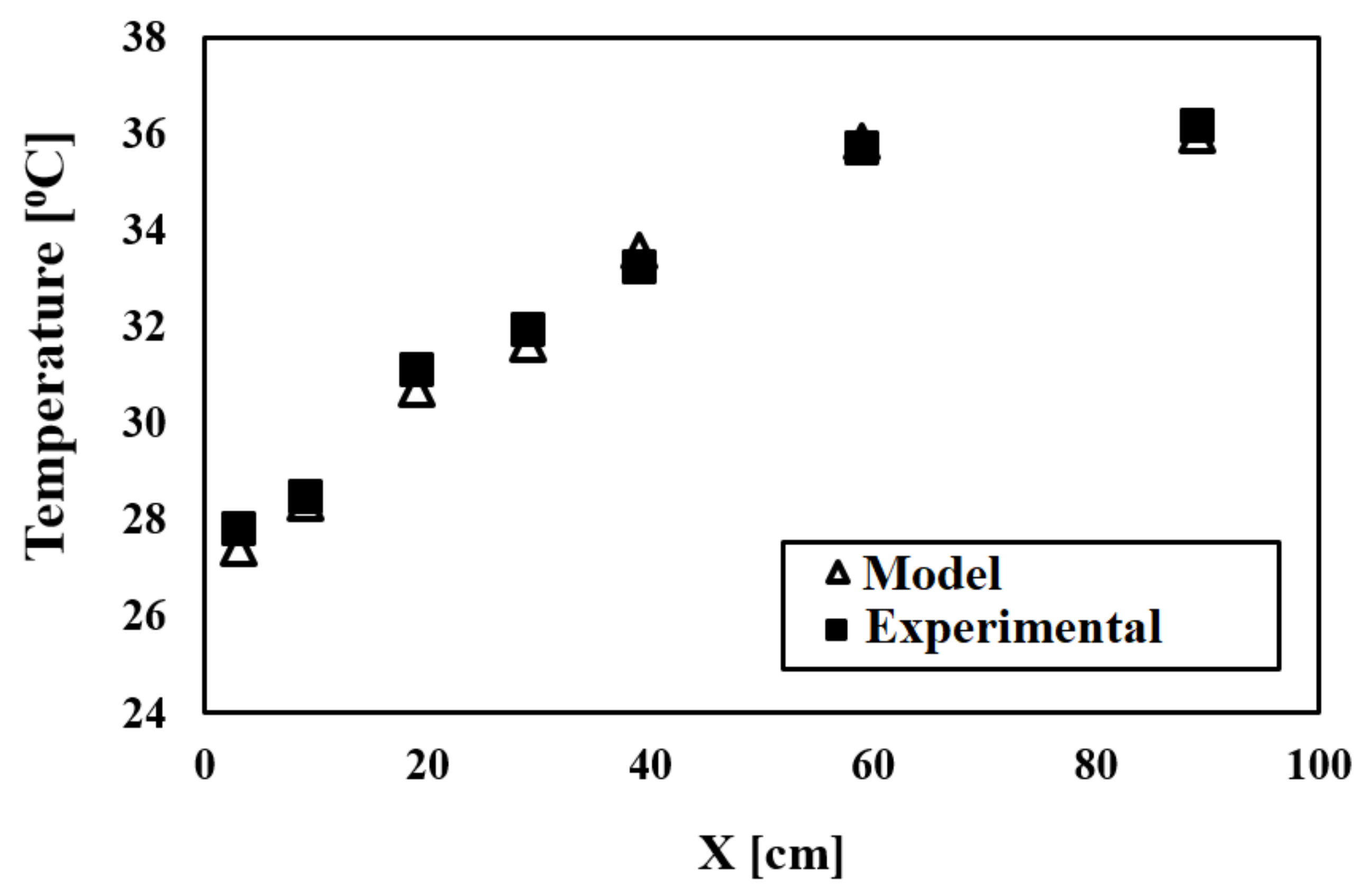
3.2. Validation of Present Study

The momentum equation for axial flow between two eccentric cylinders is compared with the results of Escudier et al. [33]. The geometry of the specific cross-section of the previous study is schematically shown in Figure 10a. The axial velocity obtained is compared with the results of [33] presented in Figure 10b. It can be seen from Figure 10b that good agreement exists between the model calculation results and the literate values. Figure 11 compares the velocity profile for the fully filled porous medium in the present paper and the experimental values of Pavel and Mohmmad [12]. Due to this symmetry, only half of the full geometry is calculated.
The average Nusselt number in annuls calculated for various eccentricities is compared with the results of [34] in Figure 12a. It is evident that the present model provides consistent results with the literature. In addition, a comparison between the local Nusselt numbers in a tube fully filled with a porous medium with Pavel and Mohmmad [12] is shown in Figure 12b.
To validate the employed numerical model with the results of the present experimental setup, the temperature values for the various positions of the sensors, according to Figure 1, were compared with the obtained results of the employed model in the Figure 13. Accordingly, it can be concluded that the utilized model has an acceptable accuracy.

3.3. Impact of Various Parameters on the Hydrothermal Behavior of Fluid Flow

Figure 14 depicts the maximum velocity increase as the thickness of the porous medium increases. This is due to the fact that by increasing thickness, the net area and radius become smaller, which will, in turn, lead to a higher maximum velocity in the constant mass flow rate. Furthermore, a larger thickness of the porous medium causes a smoother velocity profile in the porous media. As seen in Figure 15, the average Nusselt number reaches a peak at optimum thickness, which varies between 0.7 and 0.9, before falling dramatically at a constant Darcy number. At a smaller Darcy number, the optimum thickness is higher.
Figure 16 depicts that the fully developed velocity profile becomes more symmetrical at a smaller eccentricity. As the boundary layer grows to have a larger net area, the velocity reaches a higher value. The effect of thickness on the velocity profile is illustrated in Figure 17. It can be said that thickness has the same impacts on velocity in both the eccentric and concentric cases.
It is evident from Figure 18 that the pressure drop increases while the Darcy number falls. This is because the permeability of the porous medium decreases at smaller Darcy numbers. In addition, Figure 18 illustrates that, while eccentricity grows, the pressure drop decreases, with a greater decrease in lower Darcy numbers. For instance, pressure drop decreases 25 % at D a = 10 5 and   E = 0.4 . Therefore, a large pressure drop, which is one of the main problems of using porous media, can be reduced by applying an eccentric porous medium inside. Figure 19 shows that by increasing the thickness of the porous medium in the pipe, the pressure drop increases. This is due to the resistance that the solid part of the porous material creates against fluid motion.
Figure 20 shows that the eccentricity of the porous media has a significant effect on the average Nusselt number. It should be noted that the average Nusselt number experiences a significant decrease when an eccentric porous media is employed, with an even higher decrease in larger thicknesses. For example, a 50 % reduction in the average Nusselt number is caused by adding 0.1   eccentric porous media, where   E = 0.5 . Accordingly, it is not recommended to employ eccentric porous media at large thicknesses. As shown in Figure 20, at larger values of eccentricity, the average Nusselt number decreases at a smaller rate. Thus, it is beneficial to increase the eccentricity of porous media, as this leads to a smaller pressure drop and has an insignificant impact on the average Nusselt number, according to Figure 18, where eccentricity is greater than 0.3 of the outer pipe radius.

4. Conclusions

  • In the present work, force convection flow in a tube partially filled with a porous medium at eccentric posture is investigated numerically. In addition, the effects of various parameters, including eccentricity, thickness and permeability of the porous media, are studied and the following conclusions are obtained.
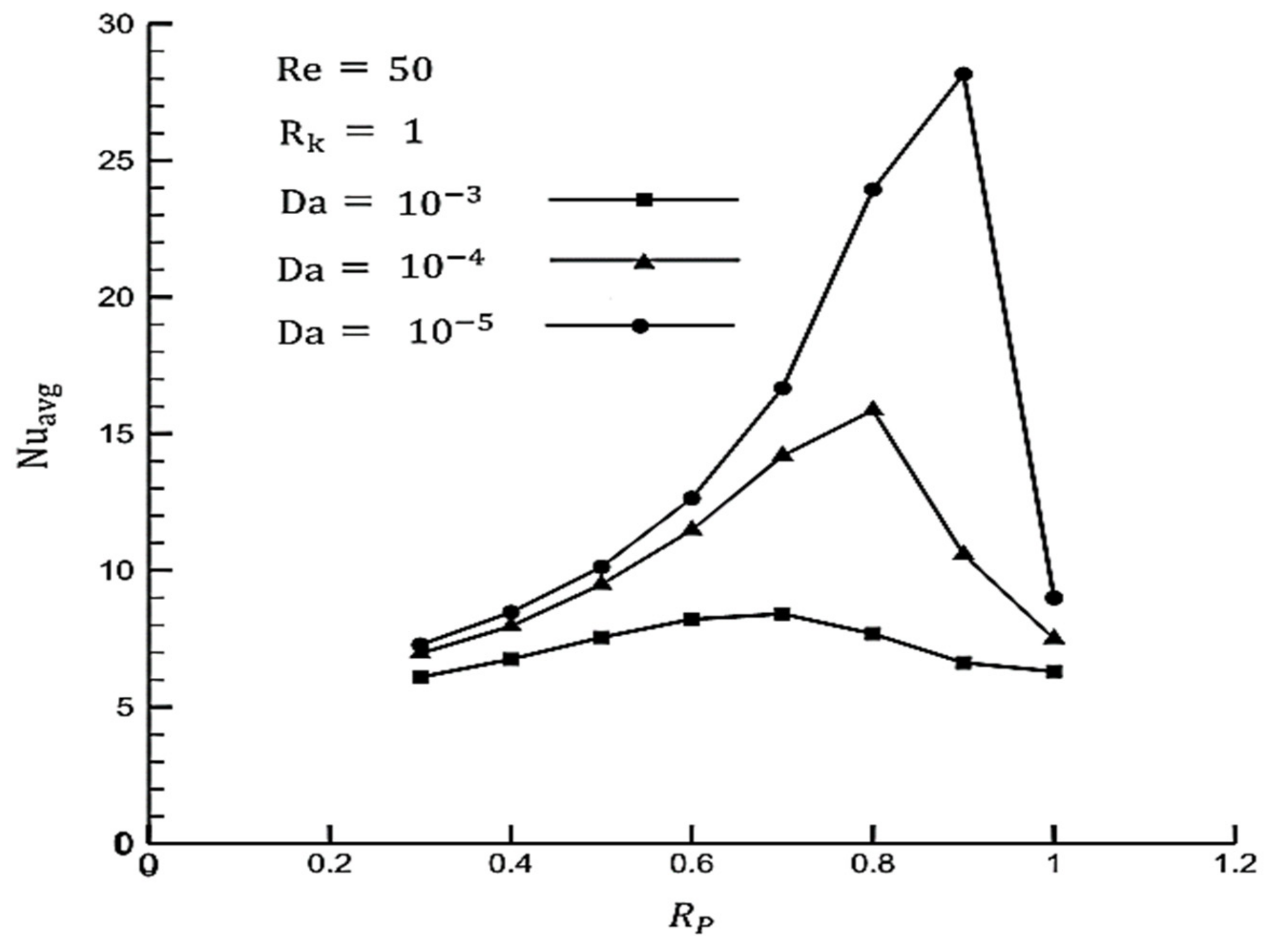
  • A smaller Darcy number leads to a higher heat transfer rate in the concentric position. In addition, the highest average Nusselt number can be achieved at a specific thickness, which is considered to be the optimum thickness for a given Darcy number. Optimum thicknesses in the range of 0.7–0.9 increase with a decreasing Darcy number.
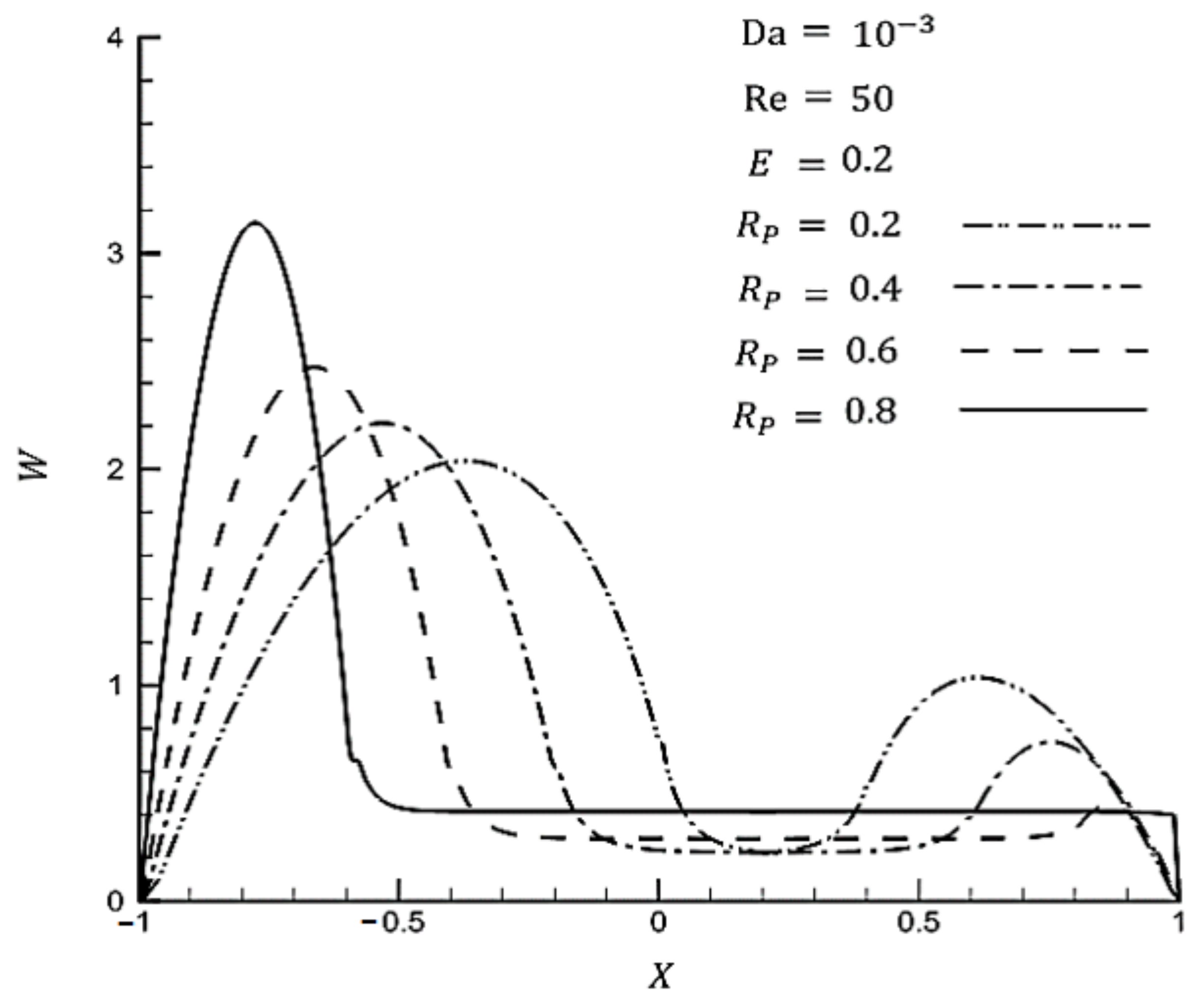
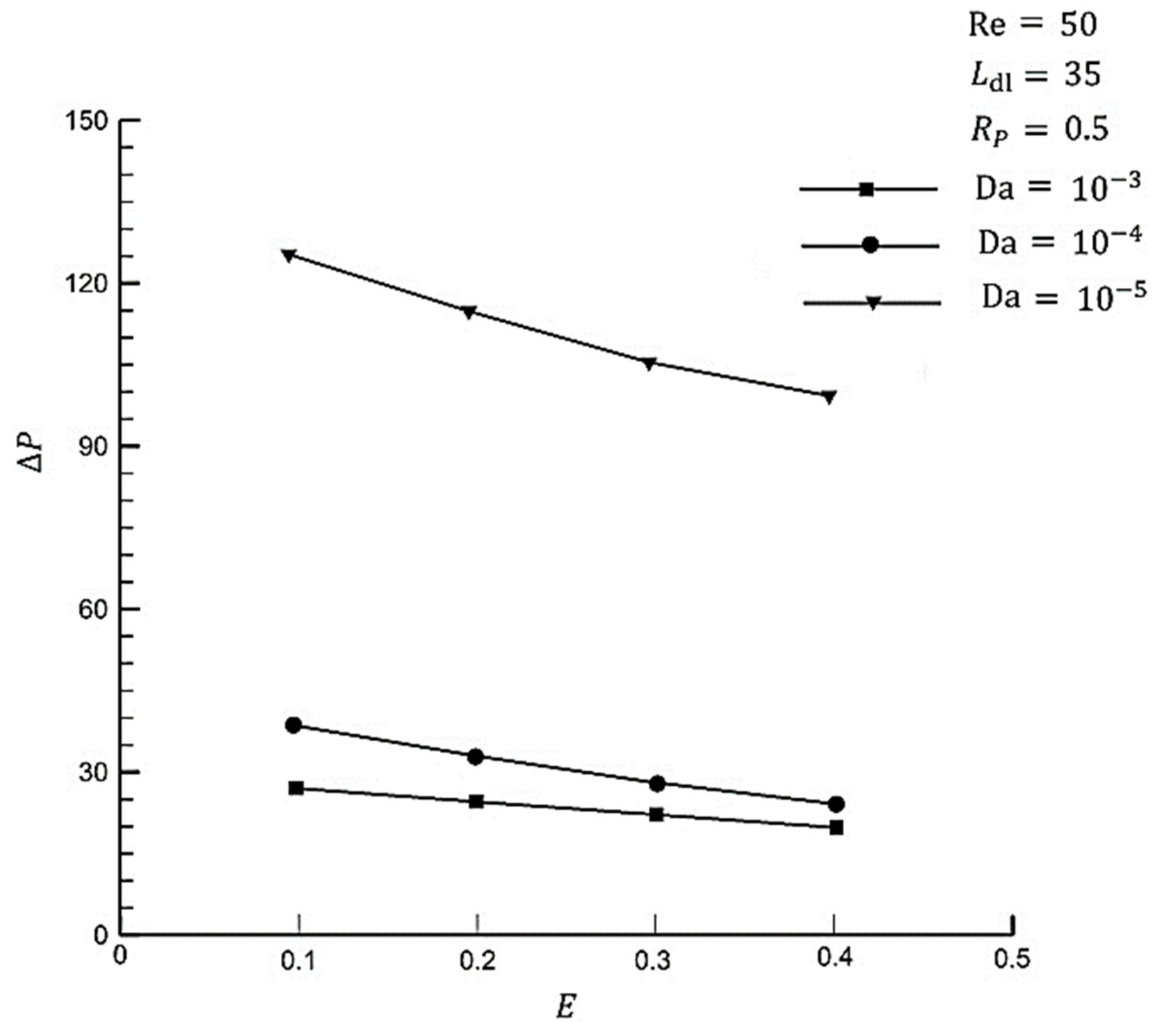
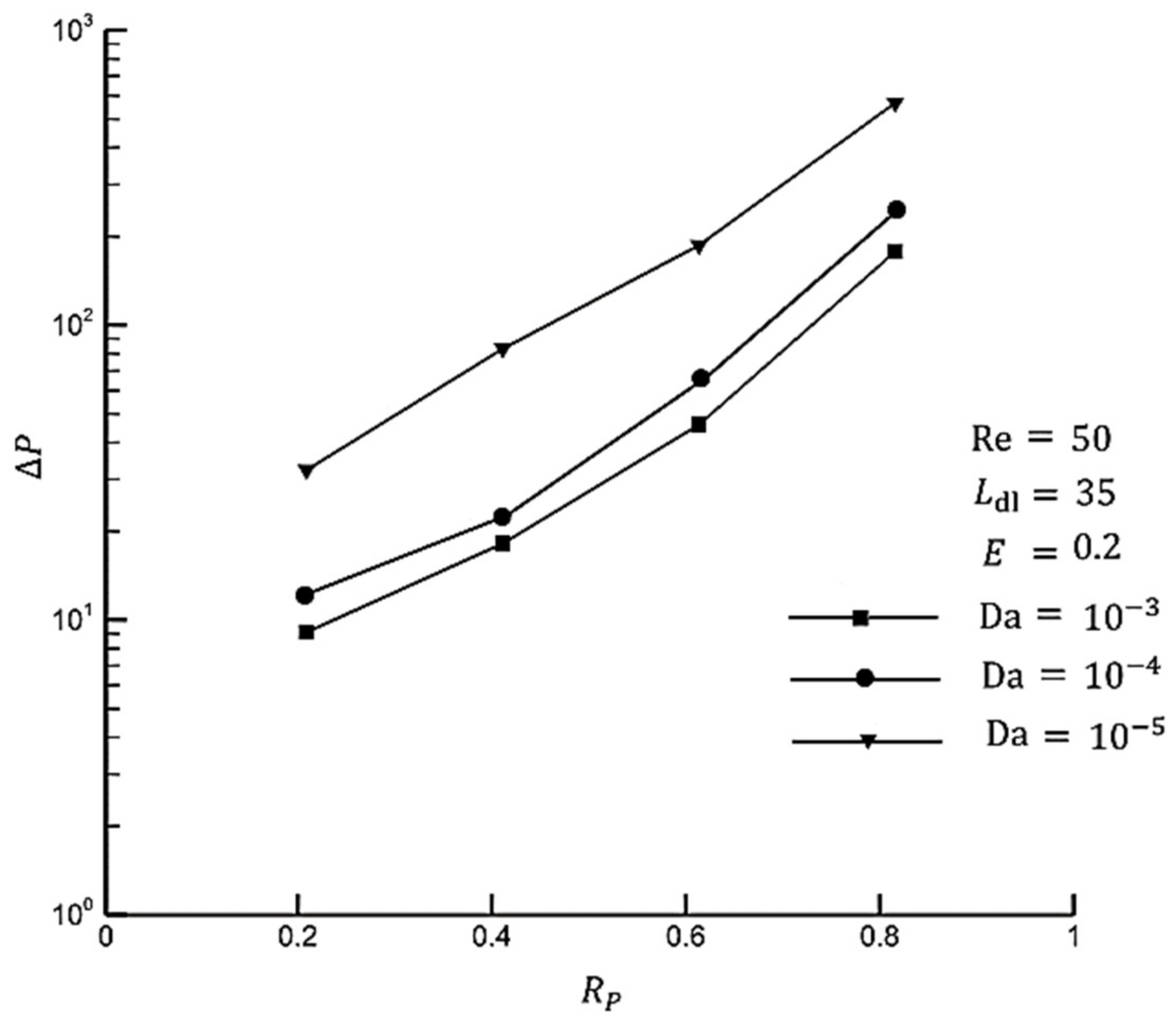
  • A decreasing Darcy number gives rise to a pressure drop. This is due to a smaller Darcy number leading to a decline in permeability. On the other hand, rising eccentricity results in a decreasing pressure drop. In addition, the reduction rate grows while the Darcy number decreases. Pressure drop falls at the fastest rate to about 25 % at D a = 10 5 and E = 0.4 . Applying eccentricity can be considered as a solution to reduce the pressure drop in porous media.
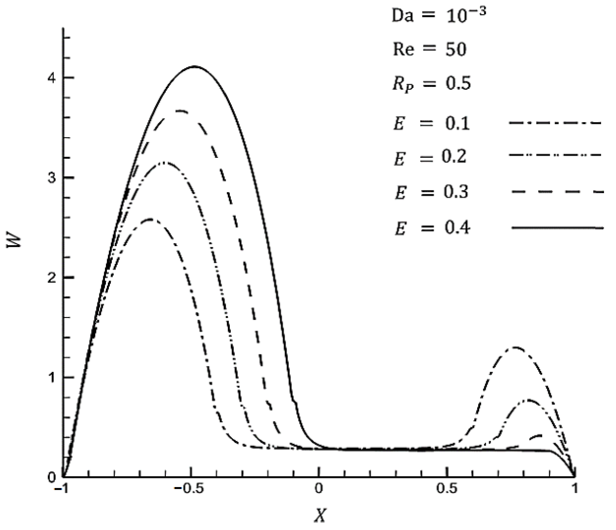
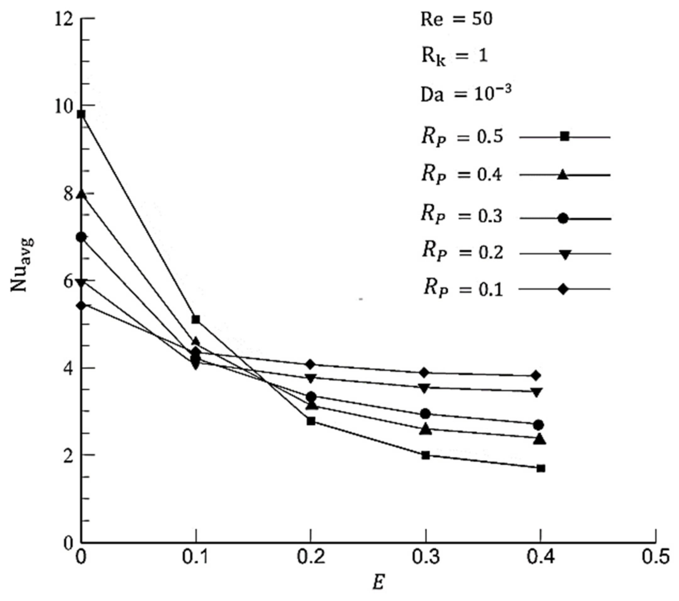
  • The average Nusselt number decreases sharply with increasing eccentricity at a high radius ratio. By way of illustration, by increasing eccentricity from 0.1 to 0.4, the Nusselt number reduces by 66 % and 11 % at   R P = 0.5 ,   0.1 , respectively. Although there is a smaller reduction at a larger eccentricity, it is not effective to apply eccentric porous media inside at a high radius ratio.
  • The average Nusselt number decreases slower in small values of thickness. As there is a slower decreasing rate for the average Nusselt number and a small pressure drop, using eccentricity is beneficial for a small range of thicknesses.

Author Contributions

Conceptualization, B.S.A. and S.S.M.A.; methodology, B.S.A. and S.S.M.A.; software, B.S.A. and S.S.M.A.; validation, B.S.A., S.S.M.A. and M.S.-A.; formal analysis, B.S.A. and S.S.M.A.; investigation, B.S.A. and S.S.M.A.; resources, N.A.; data curation, R.H.A. and N.A.; writing—original draft preparation, B.S.A. and S.S.M.A.; writing—review and editing, S.S.M.A. and N.A.; visualization, R.H.A.; funding acquisition, N.A. All authors have read and agreed to the published version of the manuscript.

Funding

This research received no external funding.

Data Availability Statement

The datasets generated during and/or analyzed during the current study are available from the corresponding author on reasonable request.

Conflicts of Interest

The authors declare no conflict of interest.

Nomenclature

B r Brinkman number ( Br = μ U in 2 /   q     r 0 ) [nd]Greek Symbols
C f Forchheimer coefficient [1/m] Γ Dimensionless group [nd]
C p Specific heat J   K 1 Kg 1 ε Eccentricity [nd]
D a Darcy number η Vertical coordinate in calculation domain
E Non-dimensional eccentric of porous media θ Angle [degree]
G Dependent parameter in governing equation μ Dynamic viscosity [ Kg . m 1 . S 1 ]
h Convective heat transfer coefficient W   m 2 K 1 ξ Horizontal coordinate in calculation domain
k Conductive coefficient ρ Density [ Kg . m 3 ]
K Permeability [ m 2 ] σ Heat capacity ratio [nd]
l Length of heated section [m] φ Fluid density [ Kg . m 3 ]
P r Prandtl number ( Pr = μ   C p / k f ) [nd]Subscripts
q Wall heat flux W . m 2 f Fluid
R e Reynolds number (Re=(v.d)/ν) [nd] e f f Effective
r i Pipe radius [ m ]-Fluid domain in the interface of fluid-porous
r s Cylindrical porous media radius [m]+Porous domain in the interface of fluid-porous
r k Heat conduction ratioAbbreviation
S G Heat source termLTELocal Thermal Equilibrium
T * Dimensionless temperature [nd]LTNELocal Thermal Non-Equilibrium
T s Surface temperature [K]
V Velocity vector

References

  1. Ajarostaghi, S.S.M.; Javadi, H.; Mousavi, S.S.; Poncet, S.; Pourfallah, M. Thermal performance of a single U-tube ground heat exchanger: A parametric study. J. Cent. South Univ. 2021, 28, 3580–3598. [Google Scholar] [CrossRef]
  2. Hashemi-Valikboni, S.Z.; Ajarostaghi, S.S.M.; Delavar, M.A.; Sedighi, K. Numerical prediction of humidification process in planar porous membrane humidifier of a PEM fuel cell system to evaluate the effects of operating and geometrical parameters. J. Therm. Anal. Calorim. 2020, 141, 1687–1701. [Google Scholar] [CrossRef]
  3. Ajarostaghi, S.S.M.; Delavar, M.A.; Poncet, S. Thermal mixing, cooling and entropy generation in a micromixer with a porous zone by the lattice Boltzmann method. J. Therm. Anal. Calorim. 2020, 140, 1321–1339. [Google Scholar] [CrossRef]
  4. Ajarostaghi, S.S.M.; Poncet, S. Thermal mixing in T-shaped micromixers with a porous block by the lattice Boltzmann method: Influence of the mixing channel configuration. Front. Therm. Eng. 2022, 15, 961083. [Google Scholar] [CrossRef]
  5. Mahdavi, M.; Saffar-Avval, M.; Tiari, S.; Mansoori, Z. Entropy generation and heat transfer numerical analysis in pipes partially filled with porous medium. Int. J. Heat Mass Transf. 2014, 79, 496–506. [Google Scholar] [CrossRef]
  6. Baragh, S.; Shokouhmand, H.; Ajarostaghi, S.S.M.; Nikian, M. An experimental investigation on forced convection heat transfer of single-phase flow in a channel with different arrangements of porous media. Int. J. Therm. Sci. 2018, 134, 370–379. [Google Scholar] [CrossRef]
  7. Baragh, S.; Shokouhmand, H.; Ajarostaghi, S.S.M. Experiments on mist flow and heat transfer in a tube fitted with porous media. Int. J. Therm. Sci. 2019, 137, 388–398. [Google Scholar] [CrossRef]
  8. Afsharpanah, F.; Izadi, M.; Hamedani, F.A.; Ajarostaghi, S.S.M.; Yaïci, W. Solidification of nano-enhanced PCM-porous composites in a cylindrical cold thermal energy storage enclosure. Case Stud. Therm. Eng. 2022, 39, 102421. [Google Scholar] [CrossRef]
  9. Ajarostaghi, S.S.M.; Zaboli, M.; Javadi, H.; Badenes, B.; Urchueguia, J.F. A review of recent passive heat transfer enhancement methods. Energies 2022, 15, 986. [Google Scholar] [CrossRef]
  10. Teggar, M.; Ajarostaghi, S.S.; Yıldız, Ç.; Arıcı, M.; Ismail, K.A.; Niyas, H.; Khalid, M. Performance enhancement of latent heat storage systems by using extended surfaces and porous materials: A state-of-the-art review. J. Energy Storage 2021, 44, 103340. [Google Scholar] [CrossRef]
  11. Mohamad, A.A. Heat transfer enhancements in heat exchangers fitted with porous media Part I: Constant wall temperature. Int. J. Therm. Sci. 2003, 42, 385–395. [Google Scholar] [CrossRef]
  12. Pavel, B.I.; Mohamad, A.A. An experimental and numerical study on heat transfer enhancement for gas heat exchangers fitted with porous media. Int. J. Heat Mass Transf. 2004, 47, 4939–4952. [Google Scholar] [CrossRef]
  13. Huang, Z.F.; Nakayama, A.; Yang, K.; Yang, C.; Liu, W. Enhancing heat transfer in the core flow by using porous medium insert in a tube. Int. J. Heat Mass Transf. 2010, 53, 1164–1174. [Google Scholar] [CrossRef]
  14. Nimvari, M.E.; Jouybari, N.F. Investigation of turbulence effects within porous layer on the thermal performance of a partially filled pipe. Int. J. Therm. Sci. 2017, 118, 374–385. [Google Scholar] [CrossRef]
  15. Mahmoudi, Y.; Karimi, N.; Mazaheri, K. Analytical investigation of heat transfer enhancement in a channel partially filled with a porous material under local thermal non-equilibrium condition: Effects of different thermal boundary conditions at the porous-fluid interface. Int. J. Heat Mass Transf. 2014, 70, 875–891. [Google Scholar] [CrossRef] [Green Version]
  16. Lin, W.; Xie, G.; Yuan, J.; Sundén, B. Comparison and Analysis of Heat Transfer in Aluminum Foam Using Local Thermal Equilibrium or Nonequilibrium Model. Heat Transf. Eng. 2016, 37, 314–322. [Google Scholar] [CrossRef]
  17. Lu, W.; Zhang, T.; Yang, M. Analytical solution of forced convective heat transfer in parallel-plate channel partially filled with metallic foams. Int. J. Heat Mass Transf. 2016, 100, 718–727. [Google Scholar] [CrossRef]
  18. Buonomo, B.; Diana, A.; Manca, O.; Nardini, S. Local Thermal Non-Equilibrium Investigation on Natural Convection in Horizontal Channel Heated from Above and Partially Filled with Aluminum Foam. Energy Procedia 2017, 126, 42–49. [Google Scholar] [CrossRef]
  19. Mahmoudi, Y.; Karimi, N. Numerical investigation of heat transfer enhancement in a pipe partially filled with a porous material under local thermal non-equilibrium condition. Int. J. Heat Mass Transf. 2014, 68, 161–173. [Google Scholar] [CrossRef] [Green Version]
  20. Torabi, M.; Zhang, K.; Yang, G.; Wang, J.; Wu, P. Heat transfer and entropy generation analyses in a channel partially filled with porous media using local thermal non-equilibrium model. Energy 2015, 82, 922–938. [Google Scholar] [CrossRef]
  21. Shokouhmand, H.; Jam, F.; Salimpour, M.R. Simulation of laminar flow and convective heat transfer in conduits filled with porous media using Lattice Boltzmann Method. Int. Commun. Heat Mass Transf. 2009, 36, 378–384. [Google Scholar] [CrossRef]
  22. Alkam, M.K.; Al-Nimr, M.A. Transient non-Darcian forced convection flow in a pipe partially filled with a porous material. Int. J. Heat Mass Transf. 1998, 41, 347–356. [Google Scholar] [CrossRef]
  23. Minkowycz, W.J.; Haji-Sheikh, A. Heat transfer in parallel plates and circular porous passages with axial conduction. Int. J. Heat Mass Transf. 2006, 49, 2381–2390. [Google Scholar] [CrossRef]
  24. Zhao, T.S.; Song, Y.J. Forced convection in a porous medium heated by a permeable wall perpendicular to flow direction: Analyses and measurements. Int. J. Heat Mass Transf. 2001, 44, 1031–1037. [Google Scholar] [CrossRef]
  25. Alazmi, B.; Vafai, K. Analysis of fluid flow and heat transfer interfacial conditions between a porous medium and a fluid layer. Int. J. Heat Mass Transf. 2001, 44, 1735–1749. [Google Scholar] [CrossRef]
  26. Shokouhmand, H.; Jam, F.; Salimpour, M.R. The effect of porous insert position on the enhanced heat transfer in partially filled channels. Int. Commun. Heat Mass Transf. 2011, 38, 1162–1167. [Google Scholar] [CrossRef]
  27. Haji-Sheikh, A.; Vafai, K. Analysis of flow and heat transfer in porous media imbedded inside various-shaped ducts. Int. J. Heat Mass Transf. 2004, 47, 1889–1905. [Google Scholar] [CrossRef]
  28. Sheikhnejad, Y.; Hosseini, R.; Avval, M.S. Experimental study on heat transfer enhancement of laminar ferrofluid flow in horizontal tube partially filled porous media under fixed parallel magnet bars. J. Magn. Magn. Mater. 2017, 424, 16–25. [Google Scholar] [CrossRef]
  29. Sheikhnejad, Y.; Hosseini, M.M.; Shahpari, A.; Teixeira, A.; Hosseini, R.; Avval, M.S. Experimental investigation and three dimensional numerical analysis of ferroconvection through horizontal tube under magnetic field of fixed parallel magnet bars. ASME J. Heat Transf. 2017, 139, 101703–101713. [Google Scholar] [CrossRef]
  30. Sheikhnejad, Y.; Ansari, A.B.; Ferreira, J.; Martins, N. Effects of parallel magnet bars and partially filled porous media on magneto-thermo-hydro-dynamic characteristics of pipe ferroconvection. Int. J. Heat Mass Transf. 2019, 136, 1273–1281. [Google Scholar] [CrossRef]
  31. Nield, D.A.; Bejan, A. Mechanics of fluid flow through a porous medium. In Convection in Porous Media; Springer: New York, NY, USA, 2013; pp. 1–29. [Google Scholar]
  32. Nejad, Y.S.; Nassab, S.G. Three-dimensional numerical analysis of hydrodynamic characteristics of axial groove journal bearings running with ferrofluids under magnetic field. Proc. Inst. Mech. Eng. Part J J. Eng. Tribol. 2010, 224, 609–619. [Google Scholar] [CrossRef]
  33. Trombetta, M.L. Laminar forced convection in eccentric annuli. Int. J. Heat Mass Transf. 1971, 14, 1161–1173. [Google Scholar] [CrossRef]
  34. Escudier, M.P.; Gouldson, I.W.; Oliveira, P.J.; Pinho, F.T. Effects of inner cylinder rotation on laminar flow of a Newtonian fluid through an eccentric annulus. Int. J. Heat Fluid Flow 2000, 21, 92–103. [Google Scholar] [CrossRef]
Figure 1. Schematic of experimental setup configuration [28,29,30].
Water 14 03832 g001
Figure 2. Schematic diagram of the computational domain, including a horizontal tube partially filled with a porous medium under local thermal equilibrium condition.
Water 14 03832 g002
Figure 3. Mapping to transform physical domain to computational domain.
Water 14 03832 g003
Figure 4. Schematic figure of domains 1 and 2 in tube cross-section.
Water 14 03832 g004
Figure 5. Generated grid in computational space for domain 1.
Water 14 03832 g005
Figure 6. Generated grid in physical space for domain 1.
Water 14 03832 g006
Figure 7. Generated grid in physical space for domain 2.
Water 14 03832 g007
Figure 8. The developed velocity contours in the space of two cylinders filled with a porous medium for various grids.
Water 14 03832 g008
Figure 9. The developed velocity contours in a tube completely filled with a porous medium for two different grids.
Water 14 03832 g009
Figure 10. (a) Schematic geometry with specified cross-section, and (b) comparison of axial velocity profile with results of Escudier et al. [33] at two different slices (AA and CC).
Water 14 03832 g010
Figure 11. Velocity comparison in fully filled porous medium with [12].
Water 14 03832 g011
Figure 12. (a) Comparison of average Nusselt in an annulus with [34], and (b) comparison of local Nusselt in tube fully filled with porous medium with [12].
Water 14 03832 g012
Figure 13. The results of the validation analysis with the present experimental results.
Water 14 03832 g013
Figure 14. Effect of porous medium thickness on velocity profile in concentric state.
Water 14 03832 g014
Figure 15. Average Nusselt for variable porous thickness in concentric state.
Water 14 03832 g015
Figure 16. Effect of porous medium eccentricity on fully developed velocity profile.
Water 14 03832 g016
Figure 17. Effect of porous medium thickness on fully developed velocity profile in eccentric state.
Water 14 03832 g017
Figure 18. Effect of porous medium eccentricity on pressure drop.
Water 14 03832 g018
Figure 19. Effect of porous medium thickness on pressure drop in eccentric state.
Water 14 03832 g019
Figure 20. Effect of eccentricity on average Nusselt number in several porous thickness.
Water 14 03832 g020
Table 1. Instrumentation and apparatuses with their resolution [28,29,30].
InstrumentationSpecificationsSensed ParameterAccuracy
Type-K, thermocoupleTesto, flexibleTw±1.0 ℃
PT100Testo, highly accurate immersionTin, Tout±0.03 ℃
PT100 Data loggerTesto 454--
Differential Pressure (dP) GaugeModel: 3051C, Rosemount, USA, Range: ±6.21 kPaDifferential pressure, ΔP±0.015% Range = 1.8 Pa
Scaled decanter2 Lit, 100 cc scaledVolume-
Type-K Data acquisitionUSB 4718, Advantech--
Ultrasonic FlowmeterFlownetix, 100 series (0.5–25 L/min)Flow rate, Q3% (reading value)
Table 2. Conservation equation parameters in computational domain.
Equations S G Γ G G
Continuity 0 0 1
Momentum in ξ direction 1 J ξ P Y η + η P Y ξ 2 Re U
Momentum in η direction 1 J ξ P Y ξ η P Y η 2 Re V
Momentum in Z direction P Z 2 Re W
Energy 0 2 Re . Pr θ
Table 3. Average Nusselt number for eccentric state with several axial grid number for RR = 0.5.
Grid Dimension 61 × 41 61 × 61 121 × 61 121 × 81
N u a v g 2.502.392.372.37
Table 4. Average Nusselt number for a tube fully filled with porous medium in Da = 10−3.
Grid Dimension 61 × 21 61 × 41
N u a v g 8.198.20
Table 5. Average Nusselt number for concentric state with several axial grid number.
Grid Number in z Direction100130160190
N u a v g 12.6112.1012.0812.08
Publisher’s Note: MDPI stays neutral with regard to jurisdictional claims in published maps and institutional affiliations.

