1. Introduction
Atmospheric ice particles, which generally appear in cirrus clouds, are an important component in atmospheric research such as remote sensing and radiation transfer. They are observed at altitudes of 7–10 km with a hexagonal shape and size of 10–1000 µm, in general. The density of particles in cirrus clouds is low in comparison with other types of clouds, but they have hard to predict scattering properties because of the specific geometry of particles. These properties are actively studied within international projects, and different methods are used: in situ aircraft measurements, remote sensing from ground and space, etc. A substantial amount of work has been done to study the properties of clouds. At the same time, many features of the light-scattering problem for ice particles are still poorly studied [
1,
2,
3,
4,
5,
6,
7,
8,
9,
10,
11,
12,
13,
14].
There are direct and remote methods for studying cirrus clouds. Direct measurements include contact measurements from aircraft [
15], and remote studies include the monitoring of the atmosphere by lidar networks and photometers. Since direct methods are limited in time and financial resources, in practice, remote methods are more useful. For interpretation of lidar data, it is necessary to solve the inverse problem of light scattering for monochromatic laser radiation. However, one needs a database of light-scattering matrices and the corresponding microphysical properties of cloud particles [
15,
16,
17,
18,
19,
20,
21]. For solving this problem, numerical methods are usually used [
22,
23,
24,
25,
26,
27].
Cirrus cloud particles can be distinguished by microphysical structure in two types: single particles (hexagonal columns, plates, bullet, etc.) and aggregates consisting of several particles. According to data of in situ measurements, atmospheric ice aggregates take a significant part of particles in cirrus clouds [
28,
29]. However, the proper information about their scattering properties is absent in existing databases. In general, crystals in clouds are arbitrarily oriented. Additionally, it is expected that light scattering by aggregates consisting of the same crystals and light scattering by a single crystal are similar in special cloud. In this case, it is possible to calculate the light-scattering matrix for aggregates using the dependence of light-scattering matrix elements on the number of particles in aggregates. However, if particles in the aggregate are compactly packed, then the direction of scattering light might be changed. Additionally, the distribution of light from a single particle might be different from the distribution for an aggregate.
The purpose of the research is to define the dependence of scattering–matrix elements on the number and arrangement of particles in the aggregate.
2. Materials and Methods
For the calculation of the light-scattering matrix, we use the physical optics approximation method [
30]. This method is the most applicable for this problem because of its capability to calculate particle parameter size
x > 10 and precise results in the backscattering direction [
31]. It was also used for solving problems related to the remote sensing of atmospheric ice crystals [
32,
33]. In this method, the particle consists of facets with multiple vertices. The method is based on the Beam-splitting algorithm [
34], which is similar to the Ray-tracing algorithm [
35], but it works with plane-parallel optical beams. In this algorithm, the particle that scatters light consists of facets, which consist of vertices with three-dimensional coordinates. The algorithm splits the light incident on facets into beams. These beams propagate in the particle and could be divided into refracted and reflected beams multiple times before they leave the particle and scatter by their cross-section frame.
The physical optics method calculates the scattering field in the near zone, within the geometrical optics approximation, and in the far zone, within both the geometrical and the physical optics approximation. However, the calculation of diffraction for each scattered beam is a very expensive operation, especially for the case of randomly oriented particles in a cloud. Most of all, the calculation time of the physical optics method increases with the number of facets in the particle. That is why, first-order, we calculated the light-scattering matrix for aggregates within the geometrical optics approximation.
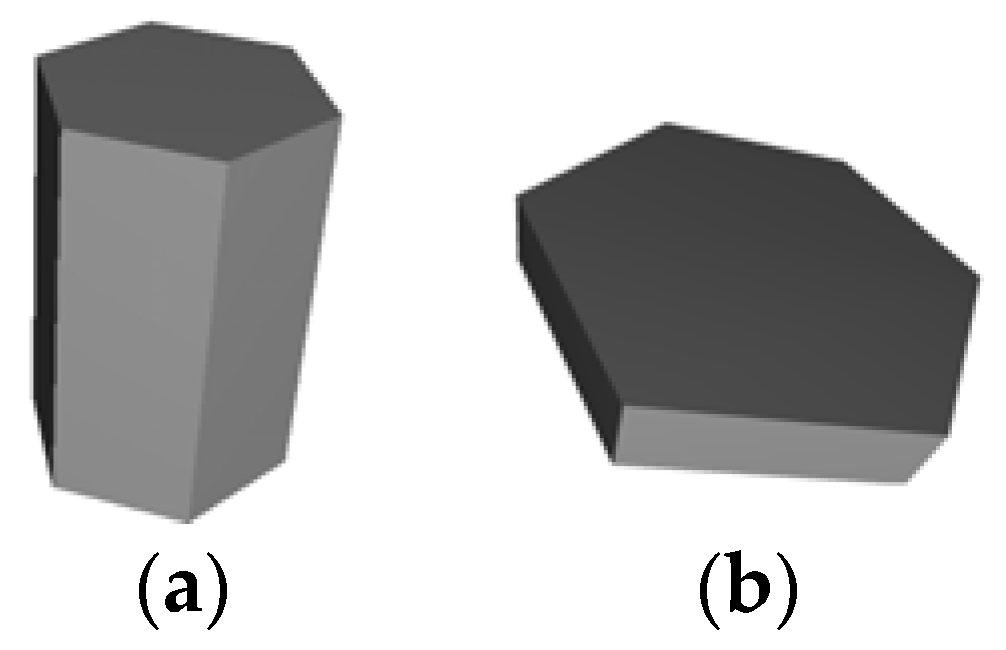
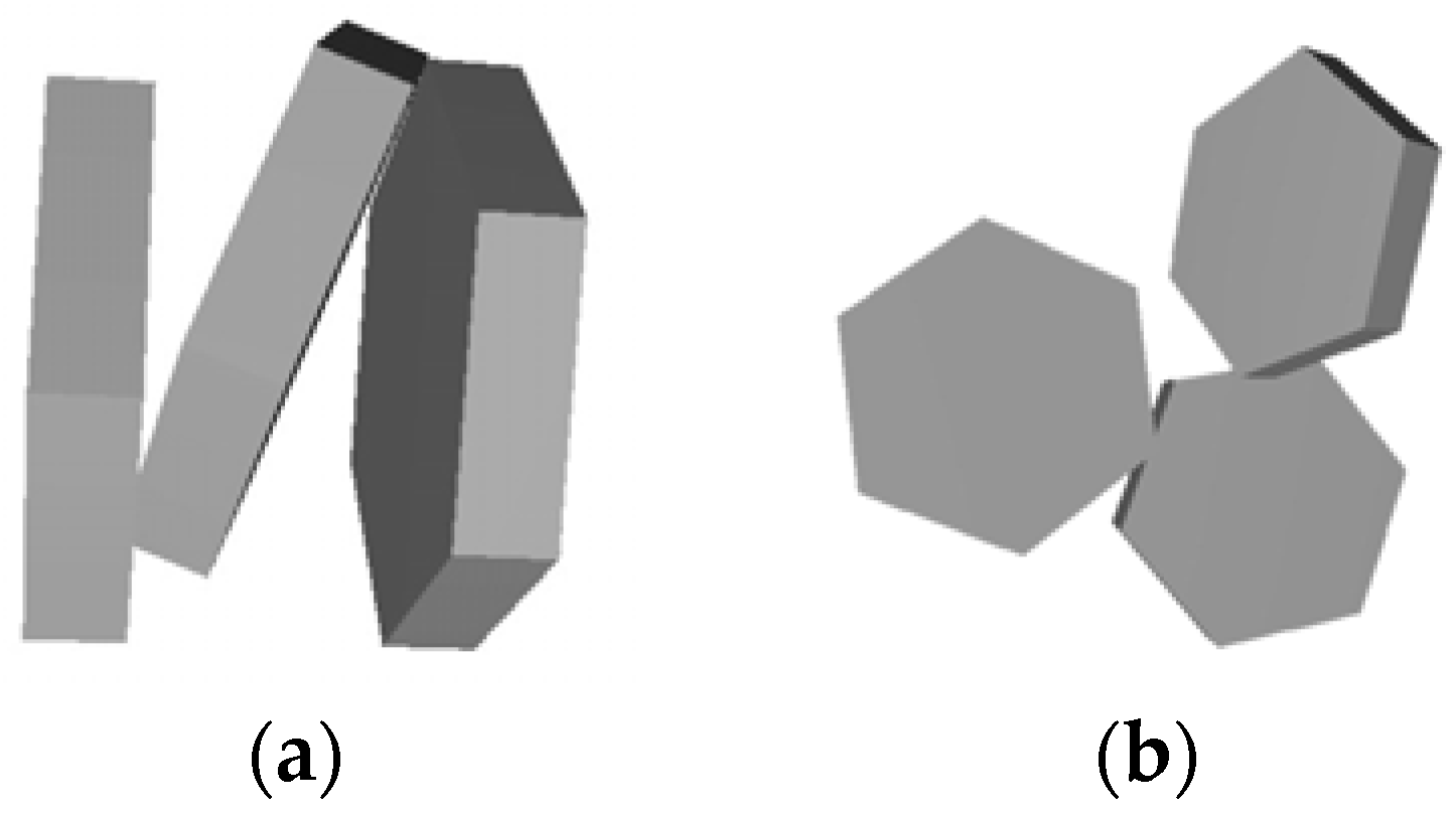
By aggregate, we mean the object consisting of several particles that are attached to each other at one or several points. The positions of these particles are fixed, but when the spatial orientation of the aggregate is changed, all particles change their position simultaneously. In this work, we use regular shapes of crystals for cirrus clouds as the basic particles for aggregates: hexagonal column; hexagonal plate [
36] (see
Figure 1).
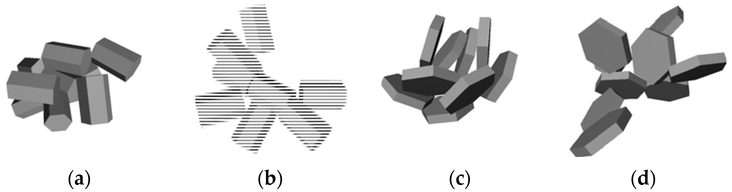
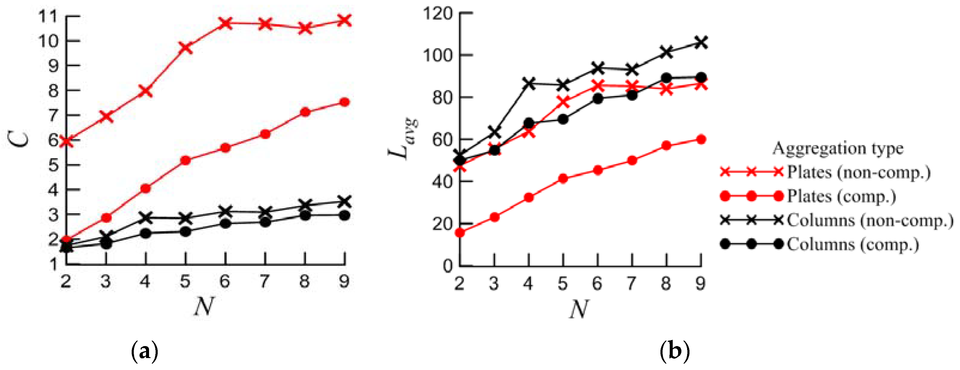
Based on the assumption that compactly packed aggregates change the direction of scattered light, two types of particle arrangements in aggregates were chosen: compact and non-compact. To determine the difference between these arrangements, we add the compactness index (
C):
where
Rmin is the radius of the inscribed sphere of the single particle, and
Lavg is the average distance between the center of each particle and the center of the aggregate, defined as follows:
where
Li is the distance between the geometrical aggregate’s center and the center of a single particle
i;
N is the number of particles in the aggregate. Coordinates of the center of the aggregate and single particle are calculated by summing the coordinates of all vertices of the aggregate and single particle, respectively, and dividing it by the number of vertices. Based on Equation (1), the most compact aggregate will have
C = 1.
In this work, aggregates are created according to the following principle: 9 particles with the same shape, size, and coordinates are generated in the center of the coordinate system. It means that they are located inside each other in this stage. Then, each particle (except the first one) is rotated by a random angle and moved away from the center in a random direction until the particles were not intersecting each other. The final aggregate consists of nine particles, which are attached to each other. This procedure was done 100 times for two shapes (see
Figure 1), and 100 aggregates with different arrangements were made. Then, the most compact and the most non-compact aggregates were chosen according to Equation (1). Finally, we made sets of aggregates with
N from two to nine by removing particles from chosen aggregates one by one. Models of aggregates of nine particles for each type are shown in
Figure 2. The following dimensions of basic particles were used: for column height 100 µm, base diameter 69.6 µm; plates height 15.97 µm, base diameter 100 µm. The particle geometry corresponds to the model in [
37]. The dependencies of
Lavg and
C on
N in the aggregate are shown in
Figure 3.
3. Calculation Results within the Geometrical Optics Approximation
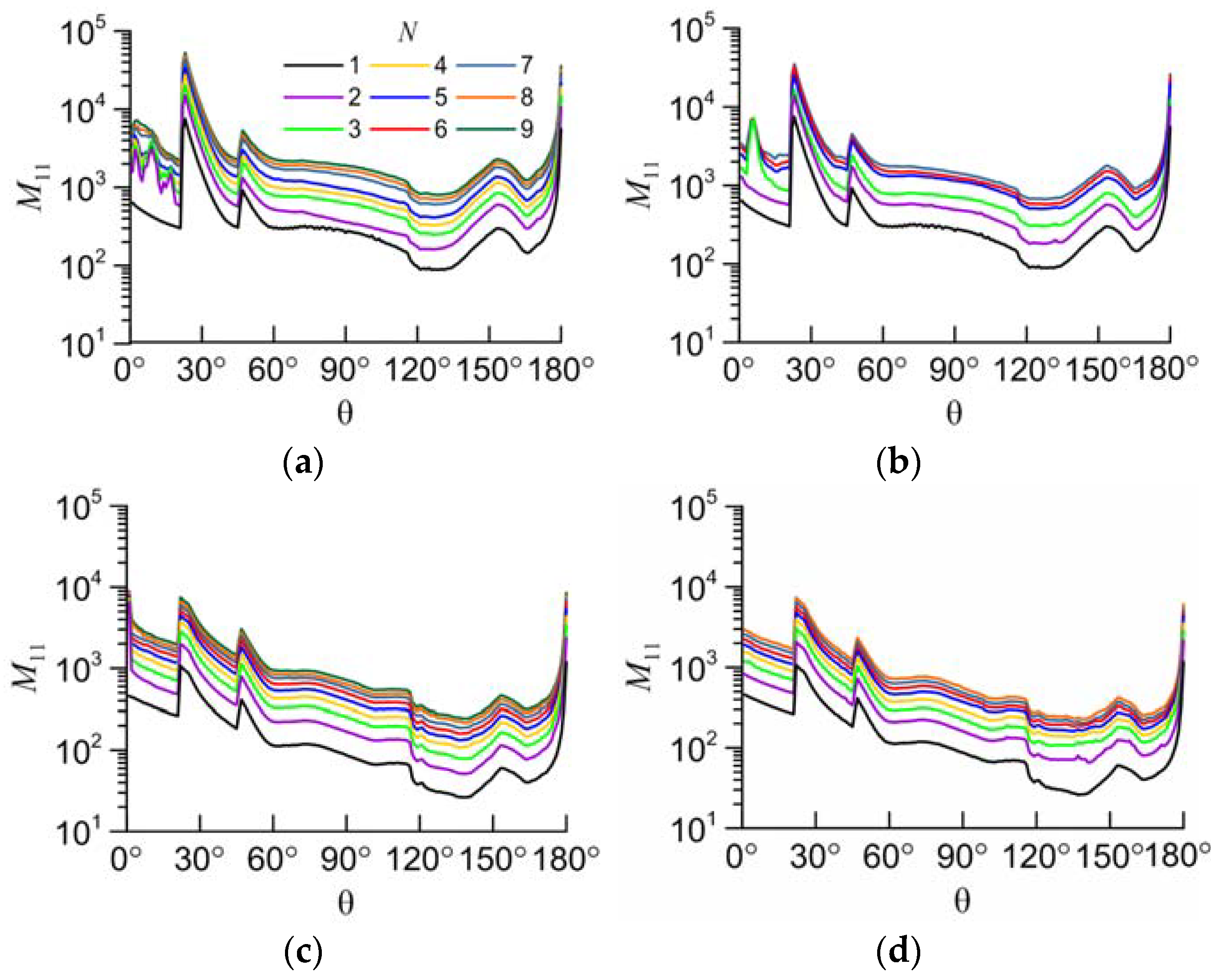
For the created aggregates, light-scattering matrices were calculated for all scattering angles within the geometrical optics approximation at the wavelength of 0.532 µm with the refractive index of particles being 1.3116 (ice water) [
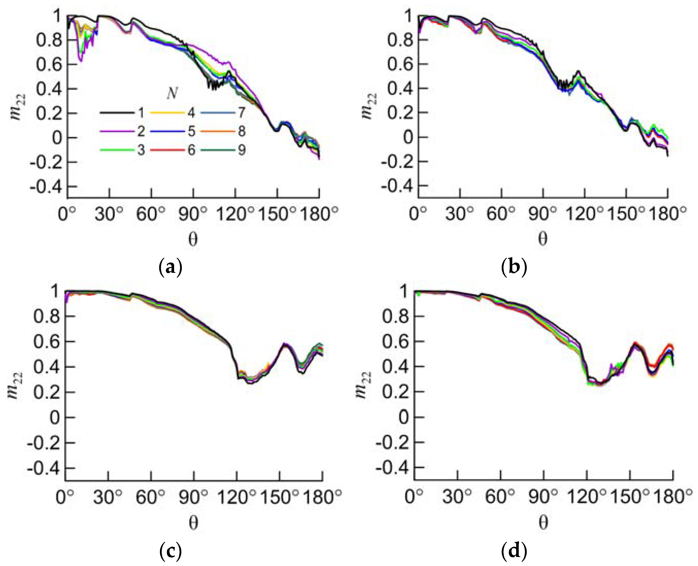
38]. Since the aggregates in a cloud are assumed to be randomly oriented, the calculation was carried out for one million orientations for each aggregate. As an example, the
M11 and
M22 elements of the light-scattering matrix are shown in
Figure 4 and
Figure 5. The value of
M11 for the scattering angle of 0° is removed from the plots because it is too high to display. The element
M22 is normalized over
M11:
m22 =
M22/
M11.
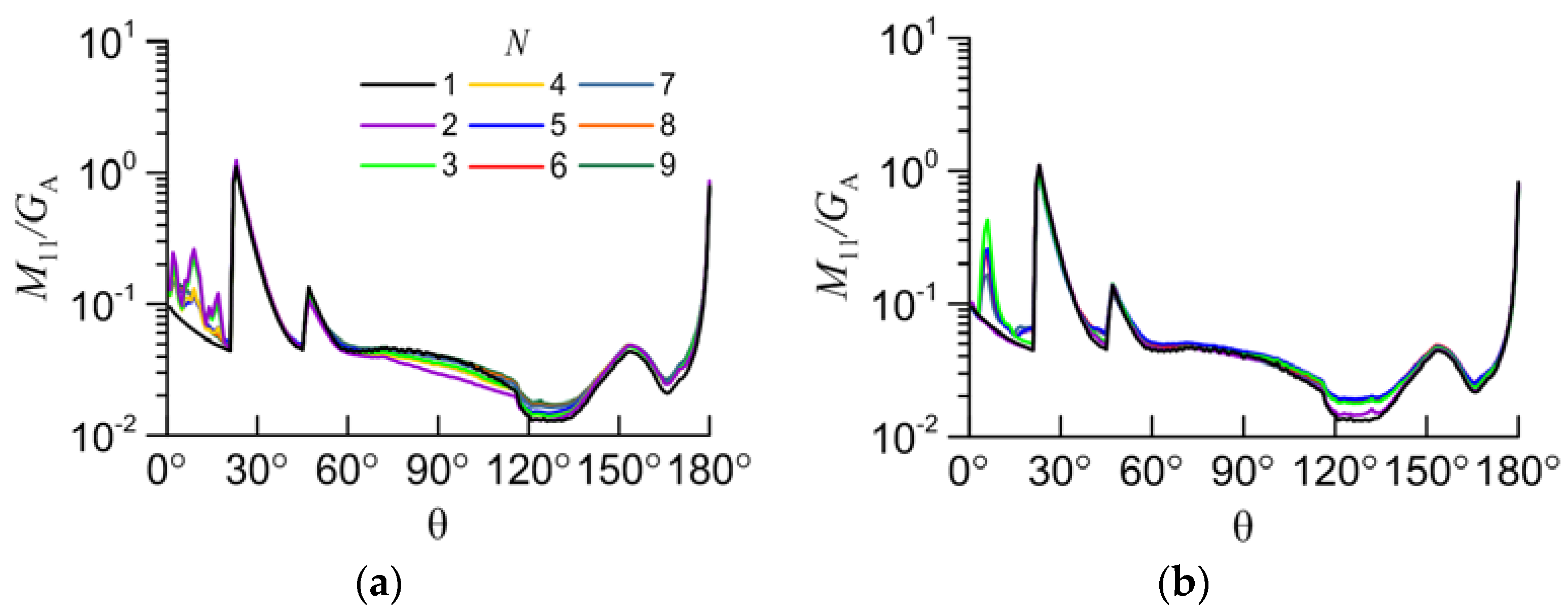
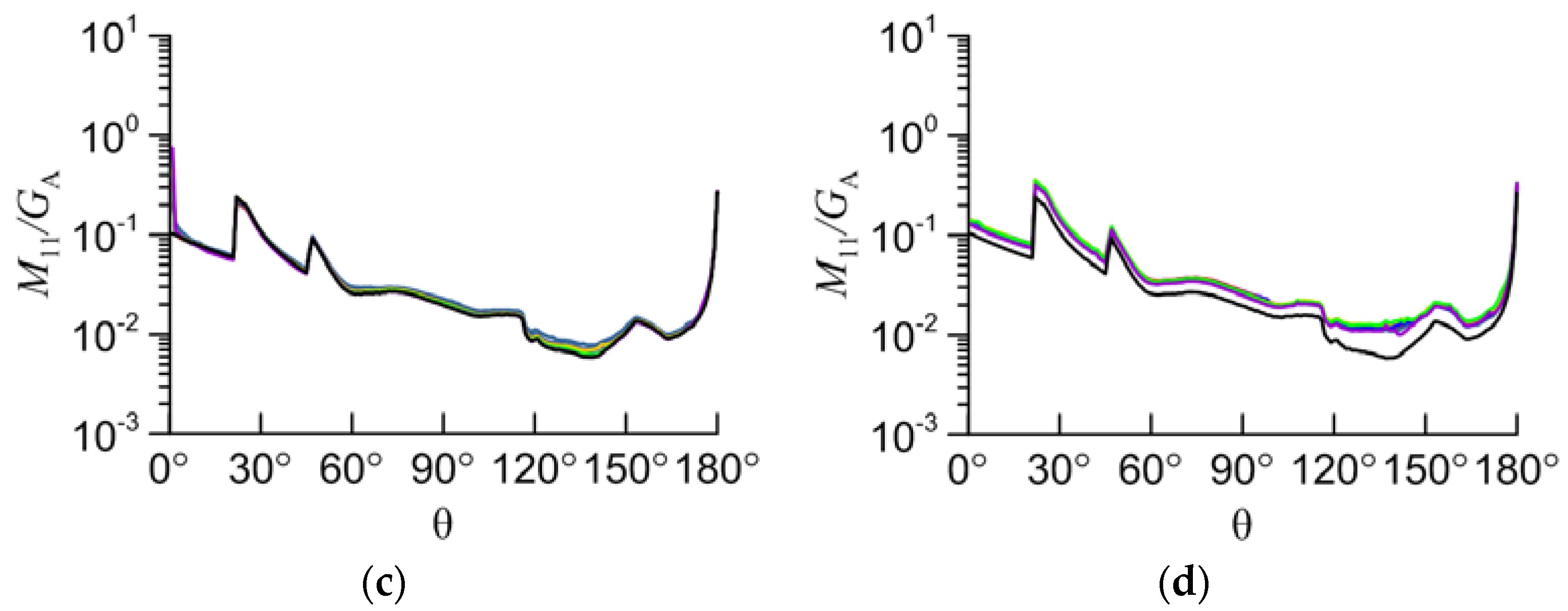
The main interest is the study of the dependence of light-scattering matrix elements on the number of particles in the aggregate (N). It is better to start the study with the element M11, which defines the intensity of light in the scattering angle (θ) for unpolarized incident light. Variability of the other elements is not critical.
Because of the fact that the scattering efficiency is equal to two within the physical optics approximation, the most informative parameter is the M11 divided by the average geometric shadow area (GA). This area can be calculated using the geometry of the aggregate without solving the light-scattering problem. The result shows that the M11/GA very slightly changes with the number of particles in the aggregate, except in the case of an aggregate of compact plates.
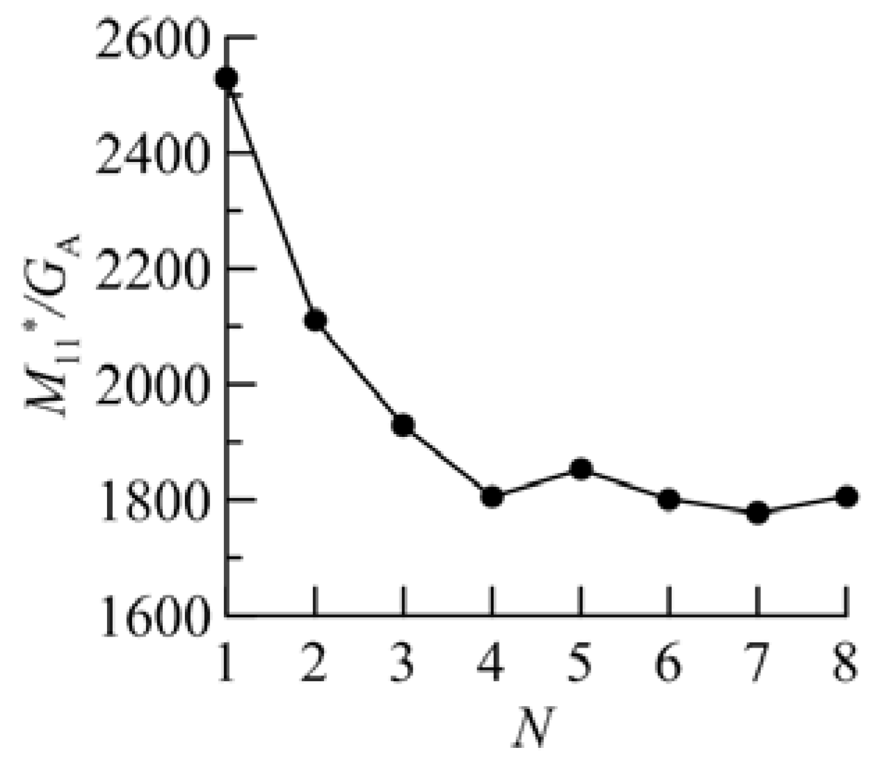
Let us examine the case of a compact aggregate of plates (see
Figure 6d). For convenience, we separately plotted
M11/
GA for the forward scattering direction for these aggregates vs.
N (
M11*/
GA in
Figure 7). In this case, the peak of intensity in the forward scattering direction is re-scattered by another plate appearing right behind the first one with an increasing number of particles. That peak is created by the forward transmission of light through the large plane-parallel facets of a plate particle. While in the case of a non-compact aggregate of plates, the particles do not overlap each other, so the light moves freely in the forward scattering direction (see
Figure 8).
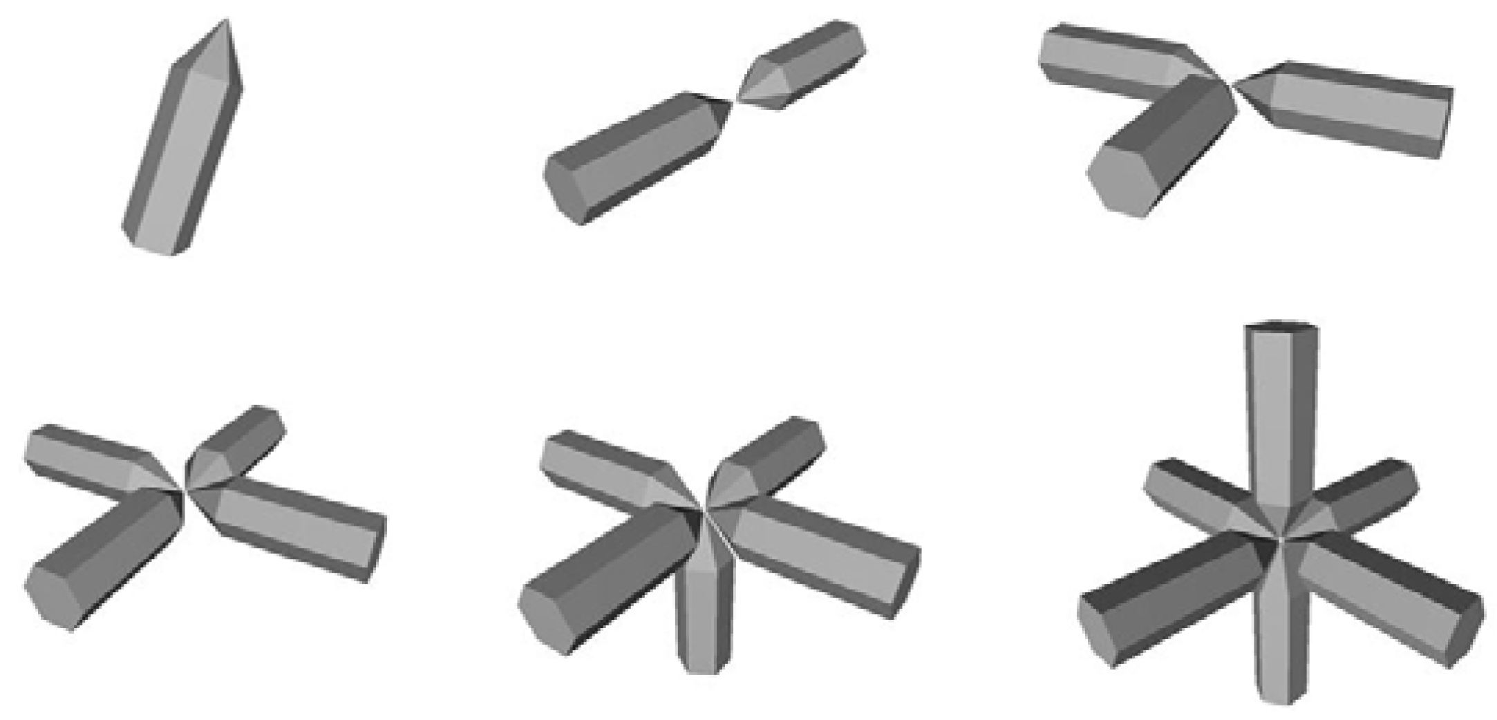
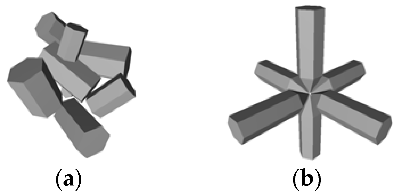
One of the typical non-compact aggregate particles in cirrus clouds is a bullet-rosette. We calculated light-scattering matrices for bullet-rosette aggregates with a number of bullets from two to six (
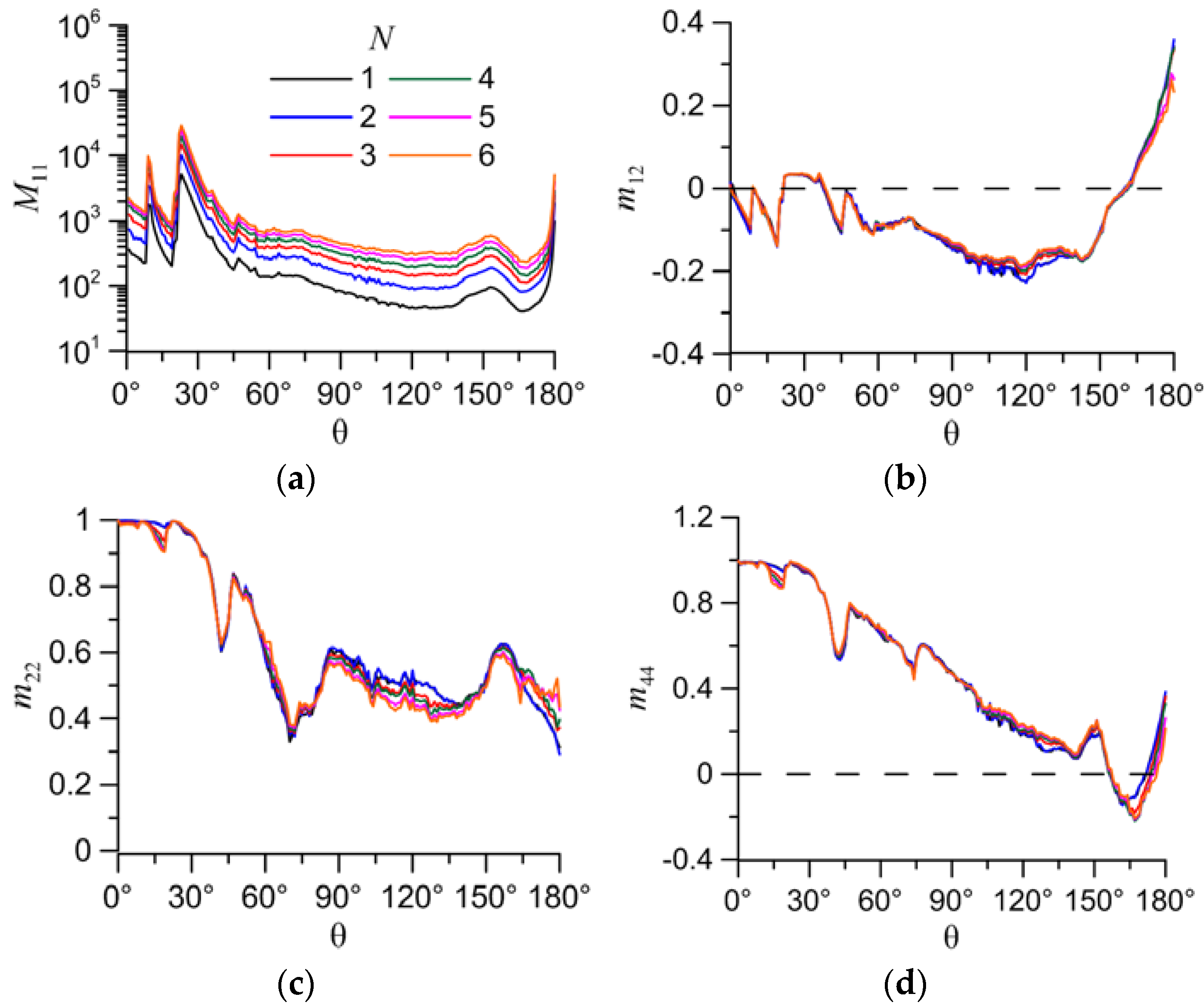
Figure 9). Unlike previous aggregates, the arrangement of particles in the bullet-rosette remains orthogonal. Calculation parameters were the same as before. The sizes of every bullet in the aggregates are as follows: the height of the hexagonal part is 100 µm; the base diameter is 42 µm; and the pike angle is 19.7°. The dependences of the elements of the light-backscattering matrix on the scattering angle (θ) are presented in
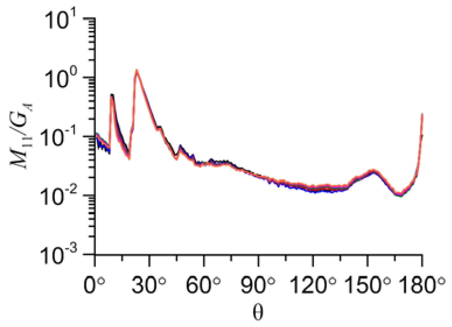
Figure 10, and
M11/
GA in
Figure 11. The normalized elements
m12,
m22, and
m44 are also shown in
Figure 11. The results show that the
M11/
GA and normalized elements
m12,
m22, and
m44 almost do not change with the number of particles in the bullet-rosette. It means that the optical properties of the bullet-rosette can be evaluated from the optical properties of one bullet.
4. Calculation Results within the Physical Optics Approximation
For the lidar application, only the physical optics solution is of practical interest because geometrical optics cannot resolve the backscattering peak of intensity of hexagonal particles. However, the physical optics solution is much more demanding on computing resources, so we examine only two aggregates of ice crystals: bullet-rosette and an aggregate of eight hexagonal columns with different sizes [
39]. The geometry for these particles is shown in
Figure 12.
For the aggregate of eight columns, the width
D and length
L for each hexagonal column are dimensionless quantities. The center of the column in the particle system is denoted by three coordinates (
x0,
y0,
z0). Then, they are scaled to obtain a proper dimension for an aggregate in calculation. The orientation of the single hexagonal column is specified by three Euler angles
α0,
β0, and
γ0, where
α0 defines rotation of the column about the vertical direction;
β0 is the angle between the vertical direction and the crystal main axis; and
γ0 describes the column rotation about the main axis. The main axis of the hexagonal column is assumed to pass through the centers of the hexagonal facets.
Table 1 lists the values of initial geometric parameters for an aggregate composed of eight hexagonal columns. Note that these characteristics are slightly different from the characteristics presented in the paper by P. Yang [
39], in order to avoid self-intersections. For convenience, we define the aggregate size through its maximal size
Dmax.
For calculations within the physical optics approximation, the bullet-rosette is composed of six bullets of the same size. The bullet shape is defined by the diameter D, the length of the hexagonal part l, and the angle of a tip, which is equal to 28° for all sizes. The relationship between the length L and the width D is D = 2.31L0.63. Sizes are given in µm.
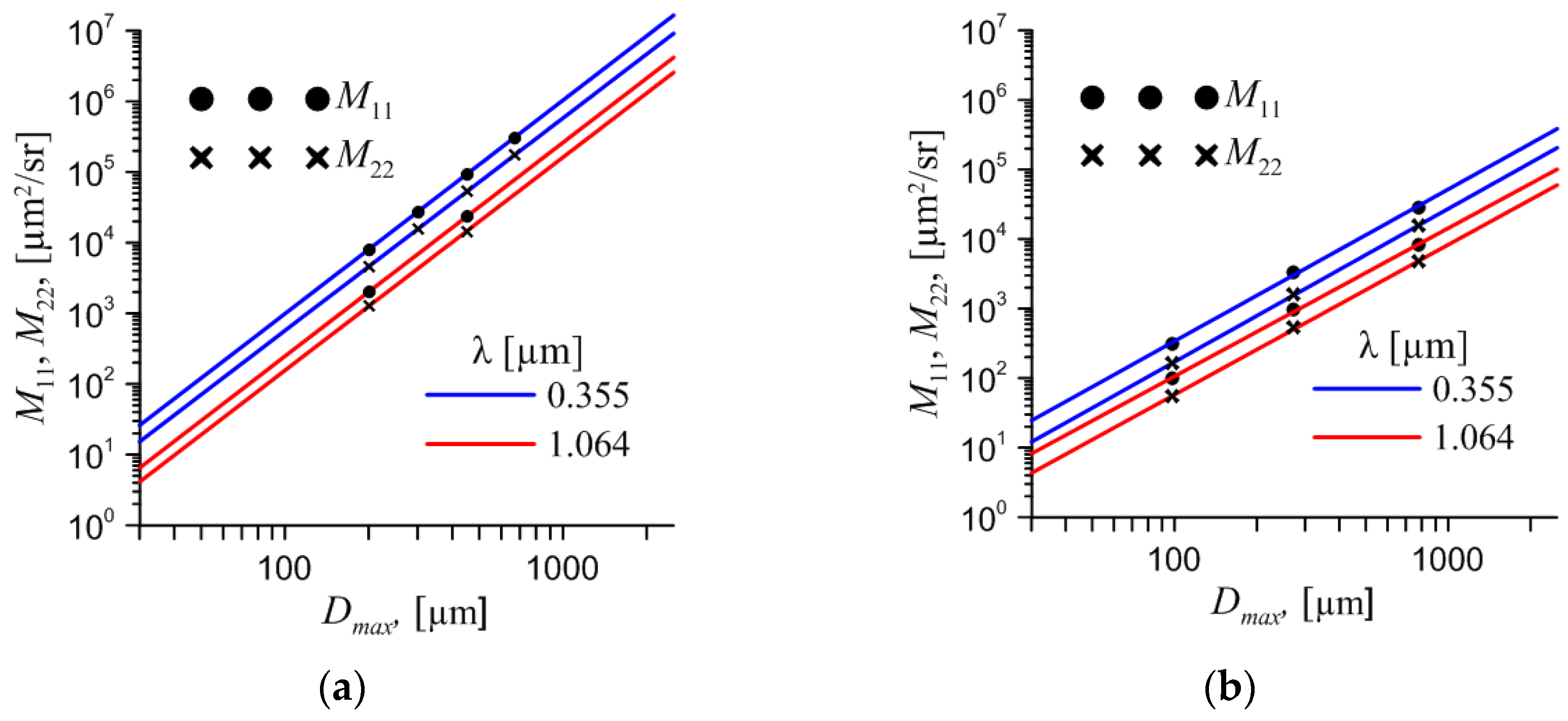
Our previous study shows that the elements of the scattering matrix obey the power laws over the particle size [
40]. Base on the conclusion of the previous section, we can assume that the scattering matrix for aggregates of particles also obey the power laws. These power laws for the aggregate can be obtained from the power law of a single particle by multiplying by the averaging geometrical cross-section of the aggregate. This fact can significantly reduce the calculation time. Since one calculation for an aggregate with the maximum dimension
Dmax = 670 µm for the wavelength of 0.355 µm takes about 18 days on a modern server with 2 Xeon E5-2660 v2 processors (40 threads), we can precisely calculate only a few of them.
The results are presented in
Figure 13. The precise calculation for the aggregate is marked as dots, the solid lines correspond to the light-backscattering matrix of a single particle, and the dashed lines correspond to the evaluation of the light-backscattering matrix of the aggregate. We can see that the light-scattering matrix of the aggregate can be obtained from the matrix of a single particle with good accuracy.
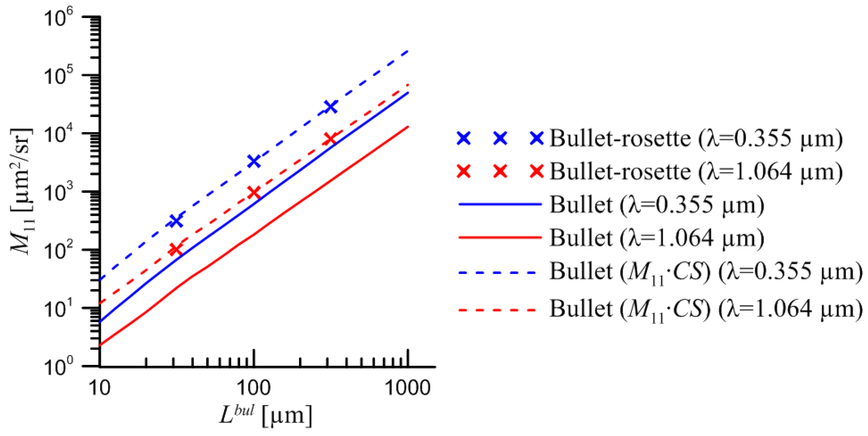
Now it is possible for us to compare
M11 for bullet-rosette (6 bullets) and for a single bullet using the existing database. Since
Dmax for aggregate and for a single particle is different, we use the dependence of
M11 on the length of a single bullet (
Lbul). Then,
M11 for a single bullet was multiplied by the total scattering cross-section for bullet-rosette. The result is presented in
Figure 14.
5. Discussion
Light-scattering matrix calculations within the geometrical optics approximation for aggregates consisting of hexagonal columns and plates with different arrangements, show quasi-linear dependencies of the first element of the light-scattering matrix (
M11) on the number of particles (
N) in the scattering-angle range of 20–180° (
Figure 6). The scattering matrix can be obtained by multiplying the scattering efficiency of a single particle by the geometrical cross-section of an aggregate. As far as the physical optics solution is obtained from the geometrical optics solution, it should also be slightly changed with increasing
N. However, this effect does not work with compactly packed-plate aggregates because of their specific geometry. This is a very important conclusion that allows us to extend the light-scattering database of a single particle to the case of aggregates of particles.
Otherwise, M11 for column aggregates shows an unpredictable distribution at angles of 0–20°. This fact can be explained by the decreasing energy at the angle of 0° (forward-scattering direction intensity peak) and redistribution of it to different directions. This energy peak is caused by light that falls orthogonal to the surface of facets and propagates through the particle without refraction. However, it can be refracted in the case of an aggregate of two or more particles when the light that leaves one particle is redirected by falling on another particle. In the case of plate aggregates, this effect is insignificant because of the similar, spatial orientation of plate particles in aggregates.
It is important to note that the calculation was carried out for two cases of individual arrangement of particles in the aggregate, and the results cannot predict the exact values of the elements of the light-scattering matrix for different aggregates. For example, the distribution of M11 in the angular range of 0–20° for a column aggregate with a different arrangement may be different. However, the main dependencies are consistent with the initial assumptions. Further studies should consider more examples of aggregates to obtain satisfactory statistics. It is also necessary to calculate the backscattering matrices in the physical optics approximation with the absorption coefficient.
The M11 for bullet-rosette shows a more predictable dependence on the number of particles. It can be obtained by multiplying M11 for a single bullet of the same size by the total scattering cross-section for bullet-rosette both within the geometrical and the physical optics approximation.
Author Contributions
Conceptualization, D.T. and A.K.; methodology, D.T., N.K. and A.K.; software, D.T.; validation, N.K. and V.S.; formal analysis, V.S.; investigation, D.T.; resources, V.S.; data curation, V.S.; writing—original draft preparation, D.T.; writing—review and editing, N.K.; visualization, D.T.; supervision, A.K.; project administration, A.K.; funding acquisition, N.K. All authors have read and agreed to the published version of the manuscript.
Institutional Review Board Statement
Not applicable.
Informed Consent Statement
Not applicable.
Data Availability Statement
Not applicable.
Acknowledgments
The authors gratefully acknowledge the computing time support provided by the IOA SB RAS supercomputer “Felix-C”. Alexander Konoshonkin acknowledges the support of the CAS PIFI (2021VTA0009).
Conflicts of Interest
The authors declare no conflict of interest.
References
- Liou, K.N. Influence of cirrus clouds on the weather and climate process: A global perspective. Mon. Weather Rev. 1986, 114, 1167–1199. [Google Scholar] [CrossRef]
- Stephens, G.L.; Tsay, S.C.; Stackhouse, P.W., Jr.; Flatau, P.J. The relevance of the microphysical and radiative properties of cirrus clouds to climate and climatic feedback. J. Atmos. Sci. 1990, 47, 1742–1754. [Google Scholar] [CrossRef]
- Takano, Y.; Liou, K.N. Solar radiative transfer in cirrus clouds. Part I. Single scattering and optical properties of hexagonal ice crystals. J. Atmos. Sci. Papers 1989, 46, 3–19. [Google Scholar] [CrossRef]
- Sassen, K.; Benson, S. A midlatitude cirrus cloud climatology from the Facility for Atmospheric Remote Sensing: II. Microphysical properties derived from lidar depolarization. J. Atmos. Sci. Papers 2001, 58, 2103–2112. [Google Scholar] [CrossRef]
- Prigarin, S.M. Monte Carlo simulation of the effects caused by multiple scattering of ground-based and spaceborne lidar pulses in clouds. Atmos. Ocean. Opt. 2017, 32, 79–83. [Google Scholar] [CrossRef]
- Samoilova, S.V. Simultaneous reconstruction of the complex refractive index and the particle size distribution function from lidar measurements: Testing the developed algorithms. Atmos. Ocean. Opt. 2019, 32, 628–642. [Google Scholar] [CrossRef]
- Berry, E.; Mace, G.G. Cloud properties and radiative effects of the Asian summer monsoon derived from A-Train data. J. Geophys. Res. Atmos. 2014, 119, 9492–9508. [Google Scholar] [CrossRef]
- Kokhanenko, G.P.; Balin, Y.S.; Klemasheva, M.G.; Nasonov, S.V.; Novoselov, M.M.; Penner, I.E.; Samoilova, S.V. Scanning polarization lidar LOSA-M3: Opportunity for research of crystalline particle orientation in the ice clouds. Atmos. Meas. Tech. 2020, 13, 1113–1127. [Google Scholar] [CrossRef]
- Marichev, V.N. Combined method for optical sensing of the lower and middle atmosphere. Atmos. Ocean. Opt. 2016, 29, 348–352. [Google Scholar] [CrossRef]
- Russkova, T.V.; Zhuravleva, T.B. Optimization of sequential code for simulation of solar radiative transfer in a vertically heterogeneous environment. Atmos. Ocean. Opt. 2017, 30, 169–175. [Google Scholar] [CrossRef]
- Kumar, A.; Singh, N.; Anshumali; Solanki, R. Evaluation and utilization of MODIS and CALIPSO aerosol retrievals over a complex terrain in Himalaya. Remote Sens. Environ. 2018, 206, 139–155. [Google Scholar] [CrossRef]
- Pauly, R.M.; Yorks, J.E.; Hlavka, D.L.; McGill, M.J.; Amiridis, V.; Palm, S.P.; Rodier, S.D.; Vaughan, M.A.; Selmer, P.A.; Kupchock, A.W.; et al. Cloud-Aerosol Transport System (CATS) 1064 nm calibration validation. Atmos. Meas. Tech. 2019, 12, 6241–6258. [Google Scholar] [CrossRef] [PubMed]
- Yang, P.; Liou, K.-N. Single-scattering properties of complex ice crystals in terrestrial atmosphere. Contr. Atmos. Phys. 1998, 71, 223–248. [Google Scholar]
- Khademi, F.; Bayat, A. Classification of aerosol types using AERONET version 3 data over kuwait city. Atmos. Environ. 2021, 265, 118716. [Google Scholar] [CrossRef]
- Heymsfield, A.J.; Bansemer, A.; Field, P.R. Observations and parameterization of particle size distributions in deep tropical cirrus and stratiform precipitating clouds: Results from in-situ observations in TRMM field campaigns. J. Atmos. Sci. 2002, 59, 3457–3491. [Google Scholar] [CrossRef]
- Reichardt, J.; Wandinger, U.; Klein, V.; Mattis, I.; Hilber, B.; Begbie, R. RAMSES: German Meteorological Service autonomous Raman lidar for water vapor, temperature, aerosol, and cloud measurements. Appl. Opt. 2012, 51, 8111–8131. [Google Scholar] [CrossRef]
- Aerosol Robotic Network (AERONET) Homepage. Available online: https://aeronet.gsfc.nasa.gov (accessed on 11 January 2023).
- Marichev, V.N.; Bochkovsky, D.A.; Elizarov, A.I. Optical Aerosol Model of the Western Siberian Stratosphere Based on Lidar Monitoring Results. Atmos. Ocean. Opt. 2022, 35 (Suppl. S1), S64–S69. [Google Scholar] [CrossRef]
- Samoilova, S.V.; Balin, Y.S.; Kokhanenko, G.P.; Nasonov, S.V.; Penner, I.E. Aerosol Layers in the Troposphere: Peculiarities of Variations in Aerosol Parameters at a Change in the Advection Direction. Atmos. Ocean. Opt. 2020, 33, 347–361. [Google Scholar] [CrossRef]
- Grynko, Y.; Shkuratov, Y.; Förstner, J. Light scattering by irregular particles much larger than the wavelength with wavelength-scale surface roughness. Opt. Lett. 2016, 41, 3491. [Google Scholar] [CrossRef]
- Zubko, E.; Videen, G.; Zubko, N.; Shkuratov, Y. Reflectance of micron-sized dust particles retrieved with the Umov law. J. Quant. Spectrosc. Radiat. Transfer. 2017, 190, 1–6. [Google Scholar] [CrossRef]
- Zubko, E.; Shmirko, K.; Pavlov, A.; Sun, W.; Schuster, G.L.; Hu, Y.; Stamnes, S.; Omar, A.; Baize, R.R.; McCormick, M.P.; et al. Active remote sensing of atmospheric dust using relationships between their depolarization ratios and reflectivity. Opt. Lett. 2021, 46, 2352–2355. [Google Scholar] [CrossRef] [PubMed]
- Purcell, E.M.; Pennypacker, C.R. Scattering and absorption of light by nonspherical dielectric grains. Astrophys. J. 1973, 186, 705–714. [Google Scholar] [CrossRef]
- Yurkin, M.A.; Moskalensky, A.E. Open-source implementation of the discrete-dipole approximation for a scatterer in an absorbing host medium. J. Phys. Conf. Ser. 2021, 2015, 12167. [Google Scholar] [CrossRef]
- Sun, B.; Yang, P.; Kattawar, G.W.; Zhang, X. Physical-geometric optics method for large size faceted particles. Opt. Express 2017, 25, 24044–24060. [Google Scholar] [CrossRef]
- Yang, P.; Ding, J.; Panetta, R.L.; Liou, K.-N.; Kattawar, G.; Mishchenko, M.I. On the Convergence of Numerical Computations for Both Exact and Approximate Solutions for Electromagnetic Scattering by Nonspherical Dielectric Particles (Invited Review). Prog. Electromagn. Res. 2019, 164, 27–61. [Google Scholar] [CrossRef]
- Liu, J.; Yang, P.; Muinonen, K. Dust-aerosol optical modeling with Gaussian spheres: Combined invariant-imbedding T-matrix and geometric-optics approach. J. Quant. Spectrosc. Radiat. Transfer 2015, 161, 136–144. [Google Scholar] [CrossRef]
- Kajikawa, M.; Heymsfield, A.J. Aggregation of ice crystals in cirrus. J. Atmos. Sci. 1989, 46, 3108–3121. [Google Scholar] [CrossRef]
- Um, J.; McFarquhar, G.M.; Hong, Y.P.; Lee, S.-S.; Jung, C.H.; Lawson, R.P.; Mo, Q. Dimensions and aspect ratios of natural ice crystals. Atmos. Chem. Phys. 2015, 15, 3933–3956. [Google Scholar] [CrossRef]
- Borovoi, A.; Konoshonkin, A.; Kustova, N. The physical-optics approximation and its application to light backscattering by hexagonal ice crystals. J. Quant. Spectrosc. Radiat. Transfer 2014, 146, 181–189. [Google Scholar] [CrossRef]
- Borovoi, A.; Konoshonkin, A.; Kustova, N. Backscatter ratios for arbitrary oriented hexagonal ice crystals of cirrus clouds. Opt. Lett. 2014, 39, 5788–5791. [Google Scholar] [CrossRef]
- Wang, Z.; Shishko, V.; Kustova, N.; Konoshonkin, A.; Timofeev, D.; Xie, C.; Liu, D.; Borovoi, A. Radar-lidar ratio for ice crystals of cirrus clouds. Opt. Express 2021, 29, 4464–4474. [Google Scholar] [CrossRef]
- Kustova, N.; Konoshonkin, A.; Shishko, V.; Timofeev, D.; Tkachev, I.; Wang, Z.; Borovoi, A. Depolarization Ratio for Randomly Oriented Ice Crystals of Cirrus Clouds. Atmosphere 2022, 13, 1551. [Google Scholar] [CrossRef]
- Konoshonkin, A.V.; Kustova, N.V.; Borovoi, A.G. Beam Splitting Algorithm for the Problem of Light Scattering by Atmospheric Ice Crystals. Part 1. Theoretical Foundations of the Algorithm. Atmos. Ocean. Opt. 2015, 28, 441–447. [Google Scholar] [CrossRef]
- Macke, A.; Mueller, J.; Raschke, E. Single scattering properties of atmospheric ice crystal. J. Atmos. Sci. 1996, 53, 2813–2825. [Google Scholar] [CrossRef]
- Yang, P.; Stegmann, P.; Tang, G.; Hioki, S.; Ding, J. Improving scattering, absorption, polarization properties of snow, graupel, and ice aggregate particles from solar to microwave wavelengths in support of the CRTM. JCSDA Q. 2018, 59, 8–14. [Google Scholar]
- Mitchell, D.L.; Arnott, W.P. A model predicting the evolution of ice particle size spectra and radiative properties of cirrus clouds. Part II. Radiation. J. Atmos. Sci. 1994, 51, 817–832. [Google Scholar] [CrossRef]
- Warren, S.G. Optical constants of ice from the ultraviolet to the microwave. Appl. Opt. 1984, 23, 1206–1225. [Google Scholar] [CrossRef]
- Yang, P.; Bi, L.; Baum, B.A.; Liou, K.-N.; Kattawar, G.W.; Mishchenko, M.I.; Cole, B. Spectrally consistent scattering, absorption, and polarization properties of atmospheric ice crystals at wavelengths from 0.2 to 100 μm. J. Atmos. Sci. 2013, 70, 330–347. [Google Scholar] [CrossRef]
- Konoshonkin, A.; Borovoi, A.; Kustova, N.; Reichardt, J. Power laws for backscattering by ice crystals of cirrus clouds. Opt. Express 2017, 25, 22341–22346. [Google Scholar] [CrossRef]
| Disclaimer/Publisher’s Note: The statements, opinions and data contained in all publications are solely those of the individual author(s) and contributor(s) and not of MDPI and/or the editor(s). MDPI and/or the editor(s) disclaim responsibility for any injury to people or property resulting from any ideas, methods, instructions or products referred to in the content. |
© 2023 by the authors. Licensee MDPI, Basel, Switzerland. This article is an open access article distributed under the terms and conditions of the Creative Commons Attribution (CC BY) license (https://creativecommons.org/licenses/by/4.0/).


