
Achieving Zero-Impact Emissions with a Gasoline Passenger Car


Chair of Thermodynamics of Mobile Energy Conversion Systems, RWTH Aachen University, 52074 Aachen, Germany
*
Author to whom correspondence should be addressed.
Atmosphere 2023, 14(2), 313; https://doi.org/10.3390/atmos14020313
Submission received: 29 December 2022
/
Revised: 30 January 2023
/
Accepted: 1 February 2023
/
Published: 4 February 2023
(This article belongs to the Special Issue Vehicle Emissions: New Challenges and Potential Solutions)
Abstract
:The Euro 7 legislation and the Zero-Impact Emissions concept aim at significantly improving air quality. Technologies that reduce pollutant emissions beyond current gasoline passenger cars have already been intensively investigated, but a holistic system layout considering extended boundary conditions is missing so far. This paper therefore develops technical solutions to achieve a Euro 7 scenario and Zero-Impact Emissions for a 2030+ vehicle. First, challenging test scenarios are identified to develop compliant vehicles. The scenarios cover extreme conditions in real-world driving, such as hot and cold ambient conditions, stop-and-go in rural areas or high speed and steep gradients on highways. Different technology options are discussed and selected for the investigations. An empirical–physical simulation model for the exhaust gas aftertreatment system is extended with new technologies, such as an electrical heater disc in front of the catalyst or a burner in the exhaust system. In addition to stoichiometric engine operation and increased catalyst volume, the results show that the expected Euro 7 regulations can be achieved in all extreme scenarios by combining additional exhaust gas heating with engine power limitation or pre-heating. Moreover, even Zero-Impact Emissions are achieved in most cases with the same technology options.

1. Introduction
Concepts for maintaining air quality and eliminating its impact on people’s health are the focus of worldwide research. For the mobility sector, efforts are being made to reduce traffic emissions beyond the current legislative standards towards ultra-low and even Zero-Impact pollutant emissions [1].
The vehicle emission discussion currently focuses on emission formation during real driving. A high-accuracy portable emission measurement system (PEMS) was introduced in 2005 [2], but large differences between the emissions under laboratory certification procedures and real-world driving were still reported for fuel consumption and CO2 [3], NOX [4] and particles [5]. With the introduction of the Euro 6d-TEMP and later the Euro 6d (EU6) emission standards, stricter nitrogen oxide (NOX) and particle number (PN) limits under various boundary conditions and real driving emission (RDE) tests were imposed [6]. Current state-of-the art EU6 vehicles in Europe have already reduced the air pollution in cities effectively [7,8]; however, the latest investigations of real-world scenarios such as cold starts after increasing parking durations still show a drastic increase in emissions [9]. Thus, clean city air is still not being achieved everywhere. The increasing pressure from society, international media, and non-governmental organizations has raised demands for further drastic improvements in the exhaust gas aftertreatment systems, especially under real driving conditions.
This is adopted by two different trends. On the one side, the Consortium for ultra Low Vehicle Emissions (CLOVE) was established by the European Commission to develop follow-up legislation for Euro 6d. This new legislation step, called Euro 7, takes a new approach in defining the limits. The limits and boundary conditions are developed independently based on the latest research status and are therefore not only a mere adaption of the last Euro 6 legislation [10,11]. On the other side, advanced hardware options are combined in the literature and used to demonstrate pollutant emissions below legislative requirements. Different terms are used for these concepts, such as near-zero emissions [12], (super) ultra-low emissions [13] or Zero-Impact Emissions [1], with differing and incomplete definitions of “emissions below legislative limits”. A first discussion of possible frameworks for these concepts was published by Eichlseder et al. [14,15]. Based on this work, Hausberger et al. developed a novel approach in [16] to define Zero-Impact Emissions as the emissions contribution to local air quality that “does not affect” the air negatively. This air quality definition was transferred to emission limits and corresponding test procedures in [17].
In parallel to the discussion of these novel legislations, technical solutions for ultra-low vehicle emissions are developed and presented [1,18]. Vehicle concepts minimize emissions of conventional combustion applications in passenger cars [19,20] and light commercial [21,22] and heavy-duty vehicles [23,24]. Suppliers mainly focus on the development and performance of hardware components. Besides the latest evolutionary steps in standard emission aftertreatment systems (EATS), such as three-way catalysts (TWCs) [25] or gasoline particulate filters (GPFs) [26,27], this also includes technologies that are not established yet, such as an electric heater [28] or additional fuel burner [29] in combination with pre-heating [30,31]. In previous research, these new technology solutions have mainly been investigated on the component level or in vehicle measurements with exemplary cycles (e.g., WLTC, Euro 6 RDE). However, there is no research yet that first identifies the most challenging scenarios that are possible in the new legislation and Zero-Impact definition, and second, tests the different hardware solutions back-to-back on the same vehicle platform from a system point of view. Therefore, a novel approach is chosen in this paper to evaluate the possible solutions for future emission concepts with a holistic methodology. First, the most challenging corner cases are chosen based on the possible boundary conditions and a comparison of possible real-world scenarios. Next, a vehicle is scaled for the year 2030+ as a basis for the investigations. Technical measures that are discussed for future emission reduction are then selected and combined with the 2030+ vehicle in an empirical–physical simulation model.
By testing future technology options under the most challenging boundary conditions for Euro 7 and ZIE, this article aims to identify promising technology combinations for ultra-low emission vehicles. This allows the reader to understand the correlation between vehicle testing boundary conditions and exhaust aftertreatment system layouts, draw conclusions for the current emission discussions and derive future catalyst development pathways. Additionally, the Euro 7 legislation and Zero-Impact Emissions concept are compared directly, both in terms of test procedures and resulting vehicle configurations. This enables policy makers to classify the remaining gap between Euro 7 and vehicle emissions that effectively do not affect air quality negatively.
2. Modeling a Gasoline Passenger Car
2.1. Simulation Approach
The holistic simulation methodology by the Chair of Thermodynamics of Mobile Energy Conversion Systems was presented for the first time in 2016 at the Vienna Engine Symposium [32]. Both the sub-models and their parameterization are continuously refined, while the real-time capability enables their use within the framework of virtual calibration by means of hardware-in-the-loop. Measurement data from the engine test bench, roller chassis dyno and dedicated component measurements are used as a basis for the model set-up. First, the vehicle model is calibrated to match the performance of the roller chassis dyno measurements. Next, the raw emissions model is set up by combining stationary engine mappings with empirical–physical correction functions that are calibrated with the vehicle measurements. The geometries and materials used in the exhaust system are implemented in a 1D model to determine the thermal behavior of the EATS. After the models for raw emissions and thermal properties are calibrated, the EATS conversion model is finalized. The model is physical–empirical and based on the measurement data of the corresponding three-way catalyst, as described in Section 3.1.3. By following this successive approach, a full vehicle model is set up that is able to replicate the emissions behavior of the measured engine, vehicle and exhaust components.
With the calibrated model, various use-cases are possible. By identifying emission-critical cycles, the model can be used to develop appropriate measures to achieve emission compliance even under the most challenging boundary conditions.
2.1.1. Raw Emission Modeling
An empirical/physical approach describes the pollutant concentrations ψi at the output of the engine for the main gaseous pollutants CO, HC and NOX. Figure 1 indicates the general structure of the model.
The composition of the exhaust gas is initially determined based on empirical measurements on a steady-state engine test bench. The emission concentration is given as a function of the input variables indicating mean effective pressure (IMEP) and engine speed. These emissions represent quasi-stationary operating points in the warm engine state and at a stoichiometric combustion air ratio. Thus, for the time being, the steady-state operation of the engine can be accurately described based on empirical measurements.
To model the dynamic operation of the engine during real driving, this map output is additionally corrected. For this purpose, empirical correlations are determined in [33] that characterize typical physical deviations from steady-state operation, such as the coolant temperature, the air fuel ratio or the spark timing. By normalizing these correlations, a factor can be determined based on the individual inputs. The combination of these physical correction factors with the empirical maps enables a corrected raw emissions output for dynamic operation.
2.1.2. Exhaust Component Characterization
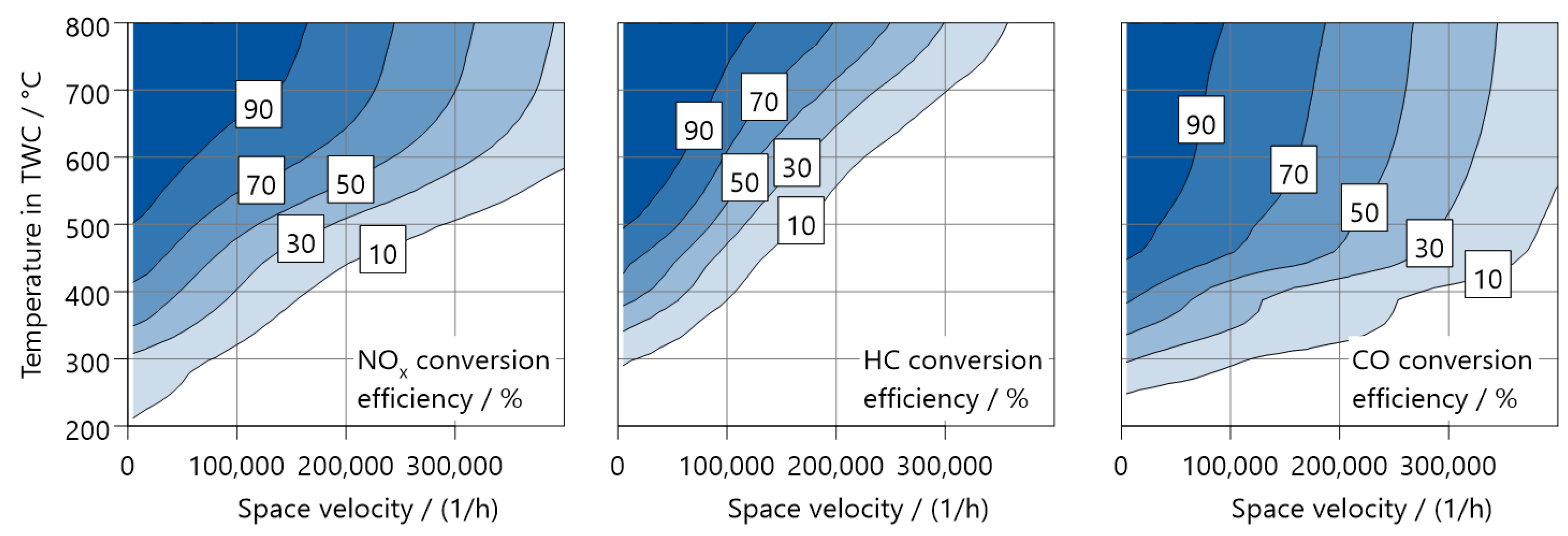
An essential part of a precise emission simulation is the correct modeling of the exhaust aftertreatment components. During the development of the RDE emission simulation methodology, it was identified that, initially, three-way catalysts could rarely be modeled with sufficient precision. For a precise prediction of the emissions under RDE boundary conditions, knowledge of the conversion rate at highest space velocities and in a wide temperature range is of interest. As a result, a unique piece of equipment was developed in [19] that can be used to characterize catalysts under exactly these conditions. The system is designed and proven for exhaust gas mass flows up to those produced by turbocharged V12 engines. The exhaust gas temperature can be cooled down to temperatures below the catalyst light-off temperature at the highest mass flows. Even under stationary engine conditions with constant engine-out emissions, this makes it possible to measure the conversion efficiency at the highest exhaust gas mass flows and cold exhaust gas temperatures, such as they can occur in a full load acceleration shortly after an engine start [19]. The result of the corresponding tests are catalyst efficiency maps, as depicted in Figure 2. The entire RDE-relevant area is covered. The exemplarily Euro 6d-TEMP catalyst shows a significantly reduced conversion rate for all components at high space velocities at stoichiometric air/fuel ratio. NOX emissions can usually be kept under control during RDE by a calibration that deviates slightly from Lambda = 1 into the rich area, which maintains a good conversion of NOX even at high space velocities. Bigger catalyst volumes are also necessary to comply with such limits when operating in the whole engine map at Lambda = 1.
Other exhaust components are characterized similarly on the testbench by adapting the methodology. For measuring secondary emissions that can also be produced in three-way catalysts, such as NH3 [34] or N2O [35], a Fourier-transform infrared spectroscope (FTIR) is added. Since the introduction of DI engines, GPFs are also applied in the EATS to reduce PN emissions [27]. For measuring a GPF with the component characterization, particle measurement systems such as a condensation particle counter (CPC) are typically combined with line sampling switches to measure both up- and downstream of the components.
2.1.3. Three-Way Catalyst Modeling
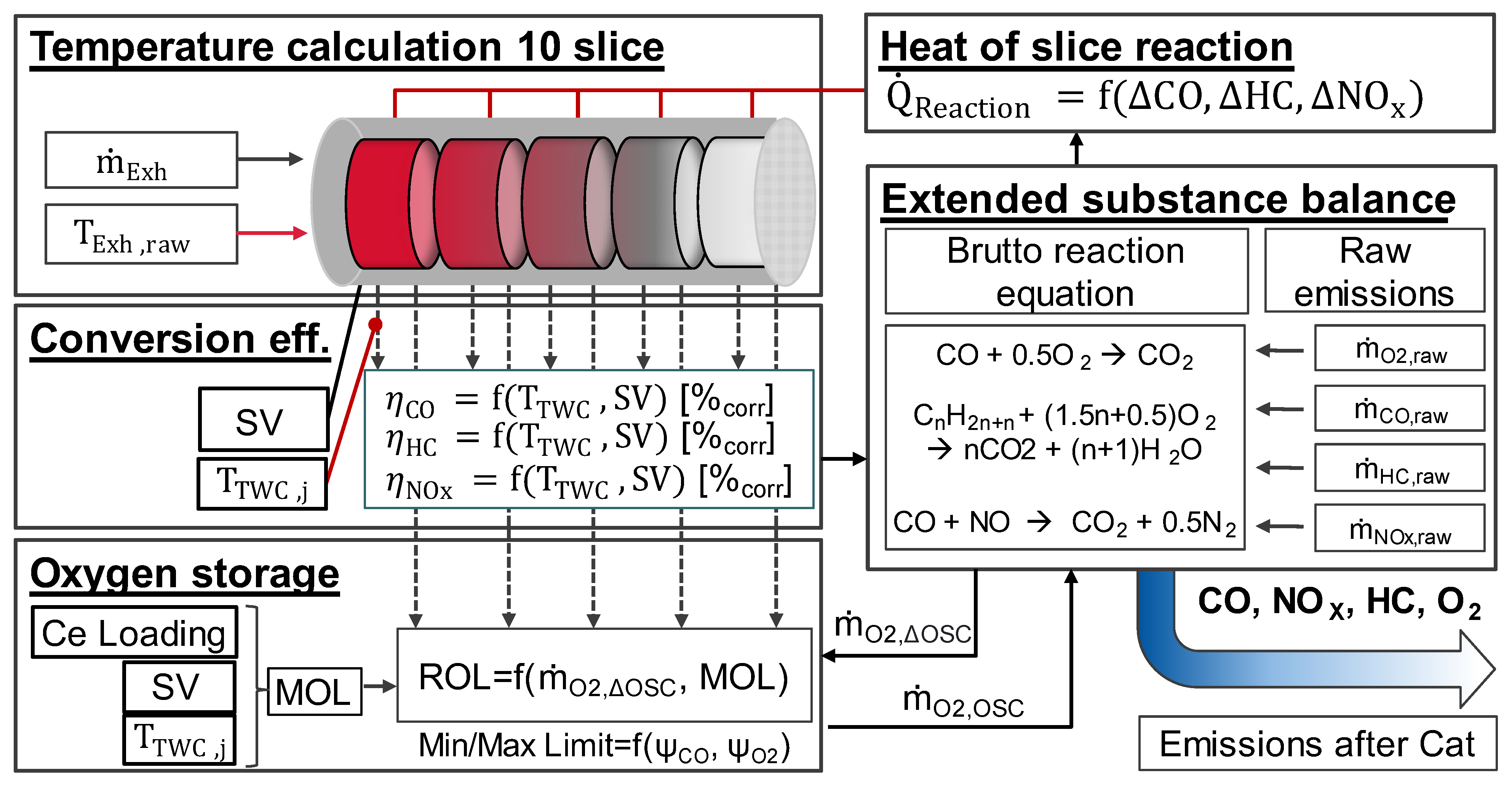
The catalyst conversion model has a modular set-up with empirical and physics-based submodules. The conversion rates within the catalyst depend on the temperature and the space velocity and describe the percentage of emission reduction within the entire catalyst. Maps for the emission groups CO, HC and NOX are created from measured data, representing the conversion rates for the cold and warm states of the catalyst. A simplified structure of the catalyst modeling is shown in Figure 3.
The core of the TWC model is the conversion efficiency based on the empirical maps generated with the methodology described previously. These maps are measured at stoichiometric air–fuel ratio, where the optimal conversion efficiency of CO, HC and NOX is achieved [36]. For deviations of the stoichiometric operation, an oxygen storage model is used. The oxygen model can be described as a flexible container with the maximum oxygen load (MOL). The MOL is dependent on the current catalyst temperature TCat, the Ceria loading Ce and space velocity SVCat; characteristic maps have been empirically determined based on test bench measurements. The available oxygen present in the exhaust gas is ṁO2,raw and the ais compared with the O₂ required for the reactions with CO and HC, ṁO2,ox (excluding the reaction of NOX with CO and HC). If there is a lack of or significant excess of oxygen, the map-based conversion efficiency is corrected based on the extended substance balance using simplified Brutto reaction equations. Finally, the heat flow of the exothermal reactions is fed back to the temperature model, where a radial and axial discretized slice approach is used to determine the catalyst temperature in spatiotemporal resolution.
2.2. Gasoline Passenger Car
2.2.1. Base Engine and Exhaust Aftertreatment
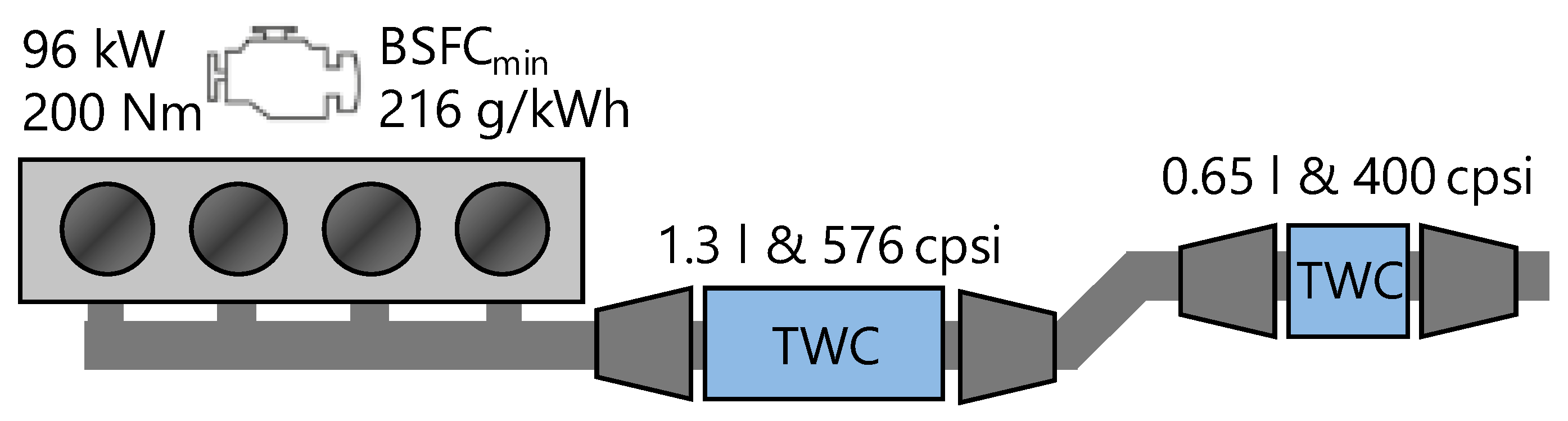
For the powertrain, a typical state-of-the-art C-class vehicle is benchmarked intensively, and the measurement data are used to set up the simulation model as described in Section 3. A turbocharged four-cylinder in-line engine is installed on the vehicle, with fuel efficient features such as Miller cycle and cylinder deactivation during part-load operation and when coasting. The engine is fitted to a seven-speed dual clutch transmission and produces up to 96 kW at 5000–6000 1/min and 200 Nm of torque at 1400–4000 1/min with its 1498 cc of displacement in a long-stroke configuration.
Based on a curb weight of 1344 kg and a tank capacity of 50 L, the vehicle manages to accelerate to 100 km/h in 9.3 s from a standstill and achieve a combined fuel consumption of 4.8 L/100 km in the New European Driving Cycle (NEDC), according to the certificate of conformity. Direct fuel injection is provided by side injectors using a rail pressure of 350 bar, enabling a minimum brake-specific fuel consumption of 216 g/kWh. Key parameters of the engine and EATS are shown in Figure 4.
Two three-way catalysts are responsible for exhaust gas aftertreatment. The first close-coupled TWC has a cell density of 576 cells per square inch (CPSI) and a volume of 1.3 L. The distance to the exhaust valves ranges from 550 to 640 mm.
The second TWC, separated by a decoupling element, has only half the volume at 0.65 L and a cell density of 400 CPSI. With a distance of 1330 to 1420 mm from the exhaust valves, it is mounted under the vehicle floor. The exhaust gases are finally routed through three mufflers that use a combination of resonance and absorption technology. For the measurements, the catalysts are aged to 160,000 km as typical for EU6 characterizations. The vehicle model and its parameters in the simulation are based on the depicted powertrain and calibrated using measurement data. This model has already been tested under Zero-Impact test conditions, and the results can be found in [17].
2.2.2. Vehicle Configuration for 2030+
In the corresponding FVV e.V. project “Zero-Impact Tailpipe Emissions”, a market projection for the year 2030+ was set to evaluate the effects of Euro 7 and Zero-Impact Emissions. A typical C-class vehicle was chosen as the benchmark for a modern gasoline-powered vehicle. The driving resistances of light-duty vehicles in Europe from 1970–2020 [37] and vehicle benchmark data from FEV [38,39] were evaluated. Based on the data and scatter bands, unweighted averages were determined and fitted with polynomial trend curves. By extrapolating the trends up to the year 2030, the vehicle parameters for this 2030+ vehicle configuration were determined and are presented in Figure 5.
As CO₂ reduction and fuel efficiency are the focus of development efforts, a decrease in the aerodynamical drag coefficient due to optimized exterior design is expected. Additionally, the tire friction is reduced by fitting smaller width, best-in-class friction tires [39]. On the other hand, increasing comfort requirements have led to bigger and heavier vehicles in the past. This trend is expected to be countered by energy efficiency calls for lightweight construction and materials, so that the total vehicle weight could stagnate [38]. The characteristic parameters that were finally chosen for the 2030 vehicle are highlighted in blue in Figure 5.
3. Identifying Challenging Test Scenarios
3.1. Euro 7 Scenarios
The European Commission’s (EC) publications and consultations with the commissioned CLOVE provide insights into the development of Euro 7 [11,40]. Table 1 compares the emission limits of the existing Euro 6 legislation with the Euro 7 limits from both CLOVE and the latest proposal by the EC.
In addition to a reduction in the pollutant limits, a key issue is the definition of new boundary conditions. The Euro 7 proposals include a considerable extension of the test area compared to the RDE boundary conditions. The temperature limit is extended to −10 °C in the lower range and to +45 °C ambient temperature in the upper range. The division of the driving cycle into the three areas of city driving, rural roads and freeways is abolished. The maximum altitude is limited to 1600–2200 m, as engines typically show deterioration effects for higher altitudes, e.g., at 3000 m [41]. Dynamic boundary conditions will be redefined and there will be a much higher or even no upper speed limit at all [10,11].
These boundary conditions cover even extreme cases, such as short urban cycles at high temperatures or Alpine pass roads at sub-zero temperatures. Dynamic boundary conditions are currently not enclosed, even though new approaches are being discussed heavily. The elimination of dynamic boundary conditions no longer permits the development of a single worst-case scenario. Instead, several driving cycles may have to be used to evaluate the vehicle’s emissions. By identifying challenging scenarios that could occur in real-world driving, a vehicle can be tested for Euro 7 compliance.
In the latest EC publication of November 2022, a final review was made “in the light of the current geopolitical and economic circumstances” [40]. The Euro 6 emission limits for passenger cars are further applied, as costs have risen drastically and sales of motor vehicles have dropped [40]. At the same time, the reference distance for short trips is reduced from 16 to 10 km and the boundary conditions for real-world driving are still widely increased [40]. In terms of emission budget for short trips, this corresponds to an increase from 480 mg NOX to 600 mg. This paper refers to the limits from the CLOVE scenario A, as a vehicle that achieves this will also be compliant with less stringent limits.
3.2. Challenging Real-World Scenarios for Euro 7
In the Euro 6 legislation, worst-case RDE cycles could be identified with statistical methods and simulation-based optimization [6]. This was possible because there were various boundary conditions and dynamic limitations that limited the solution space. However, for both Euro 7 and Zero-Impact Emissions, there are barely limiting conditions and effectively most real driving situations are possible. As a synthetic generation of cycles is not reasonable anymore, distinctive profiles for real-world driving cycles must identified. Therefore, a new approach to generate such representative cycles was used considering different environments, driver behaviors and traffic conditions. This was developed in synergies by two projects from the FVV: “Zero-Impact Tailpipe Emissions” and “HyFlex-ICE” [42]. The specific cycles were then derived using an existing tool chain and processed via appropriate data sources (e.g., HERE HD, Google Maps) to define the real-world driving scenarios based on specific acceleration characteristics over travel distance as the simulation input.
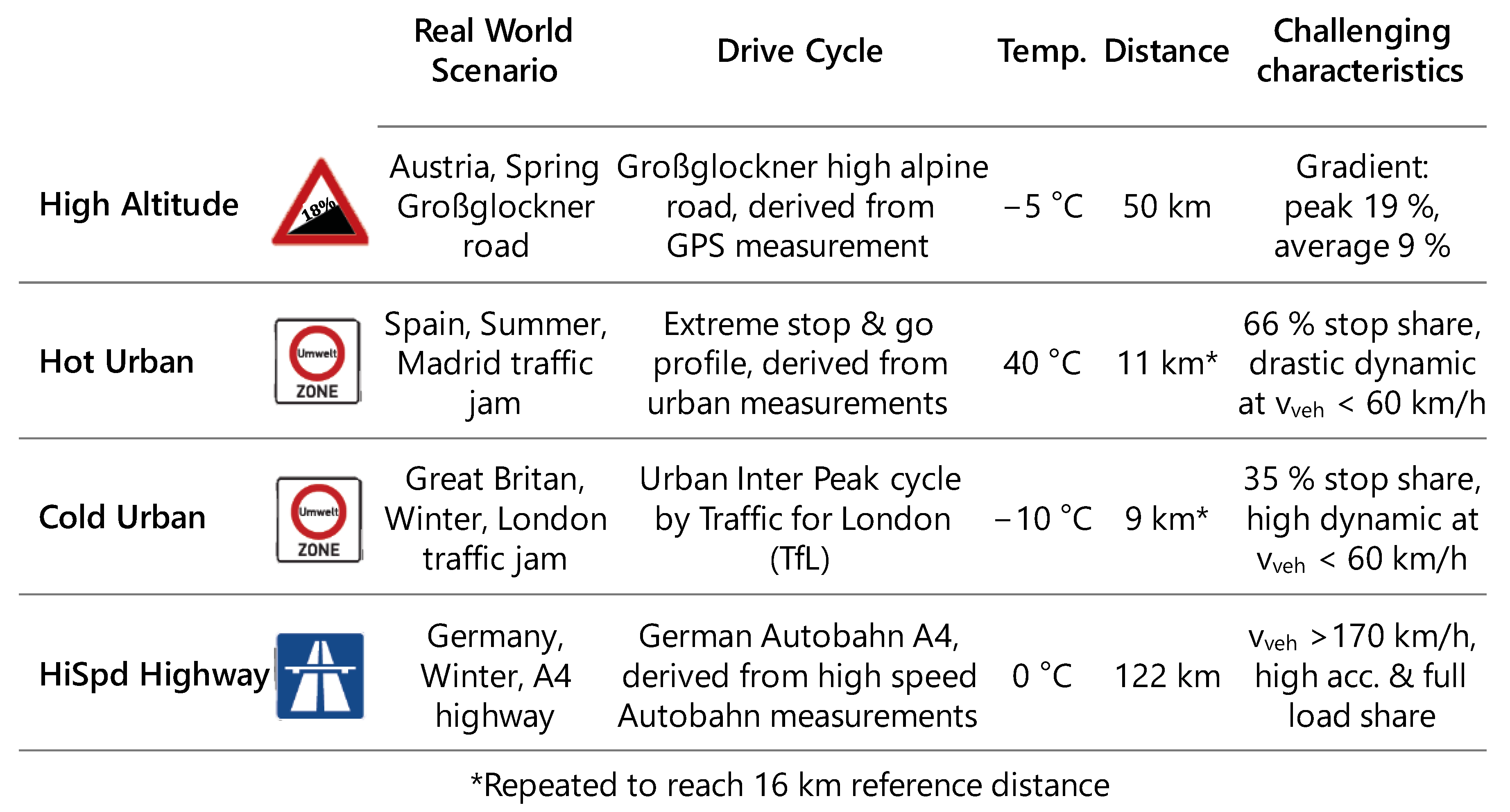
With the extended boundaries of the proposed Euro 7 legislation, almost any scenario that is possible in real-world driving could be tested. In general, this could also include, e.g., repeated accelerations and decelerations with maximum dynamics on a highway. In the corresponding FVV project “Zero-Impact Tailpipe Emissions”, it was concluded that scenarios should be found that are the most challenging to achieve, but are still representative of real-world driving. This meant the exclusion of any synthetic and unrealistic driving, which was later addressed in the EC Euro 7 draft by implementing a dynamic restriction of the normalized wheel power [40]. Hence, four representative cases were selected in the corresponding FVV project based on the discussions with the industry partners. These scenarios typically pose a big challenge for the emission control system, and similar test cases are already used in the Euro 7 concept development of the industry. The scenarios include high load demands, high gradients, and high stop shares with dynamic operation at both cold and warm ambient conditions. More details on the discussions and methodology to identify real-world cycles are found in [17] and [43]. Figure 6 gives an overview of the developed test scenarios for the Euro 7 evaluation.
The cycles were selected based on an extensive project discussion to include representative cases that are challenging from all relevant technical aspects. This includes both cold and warm conditions, urban stop-and-go and high-speed highway driving. The cycle traces can be found in the Appendix A of this paper.
3.3. Zero-Impact Emission Definition and Test Scenarios
The most challenging conditions for the emission control system can be combined and tested directly for emission-focused legislations such as Euro 7. This can also result in a cycle such as the High Altitude cycle (see Figure 6), where typically only very few vehicles would drive and the dilution with the ambient air is high. For the air quality, this case is not critical, even if the passing vehicles emit a high volume of pollutants. Therefore, for testing an air quality-based concept such as Zero-Impact Emissions, both air quality and pollutant emission aspects need to be considered.
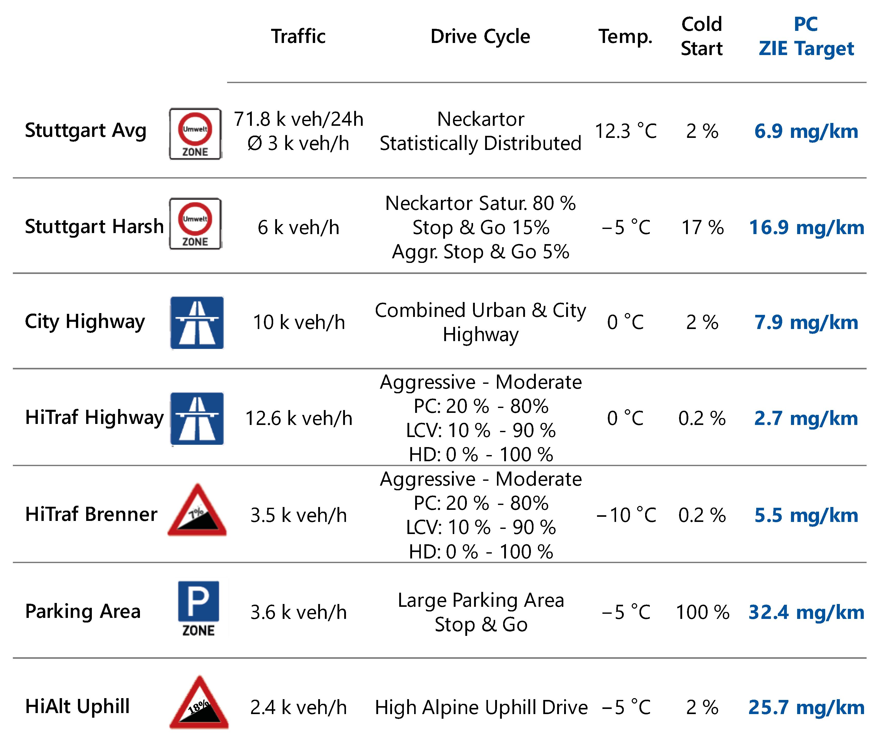
In the corresponding project by Hausberger et al. [44] for the FVV e.V., a 3% irrelevance threshold was defined for “Zero-Impact traffic contribution” to local air quality. With this approach, the emission factors that the vehicles may emit depend highly on the boundary conditions, and there is no fixed emission limit. Based on this, a universal methodology was developed that transfers ZIE levels to individual boundary and environmental conditions [17]. Different scenarios were derived from real-world situations that are both critical in terms of air quality and pollutant emissions. For each scenario, the parameters are described in detail in [17] and the cycle data are publicly available [45]. The boundary conditions and the individual emission target for the passenger cars are summarized in Figure 7.
As demonstrated by [46], fleet composition and boundary conditions, such as vehicle speed limits, have an impact on air quality, especially for streets with high pollutant concentrations. The additional scenarios are therefore typically a combination of emission-critical conditions, such as a high cold start share or highly dynamic operation, and aspects that are problematic from an air quality perspective, such as high traffic volumes or low pollutant dilution due to low air exchange.
Studies have shown that high dynamics increase emissions in urban cycles [47,48]. Therefore, the yearly average Stuttgart Neckartor scenario is adapted for an hour-specific worst-case situation with high dynamics.
As shown by [49], there is also a strong correlation between NOX emissions and the engine power requirements. Due to the high speed, highways are also quite emission critical, especially when combined with steep gradients and high traffic flow. Three cycles are introduced, one derived from a high-traffic highway such as the German Autobahn A4, one from a busy city highway, and one from the Brenner Autobahn between Austria and Italy.
Finally, two scenarios that combine extreme situations with very small occurrence are developed: a full parking lot with a very high cold start share (e.g., after a concert in winter) and a touristic mountain road passage with extreme gradients.
4. Advanced Emission Control Technologies
4.1. Base Technologies for Future 2030+ Vehicles
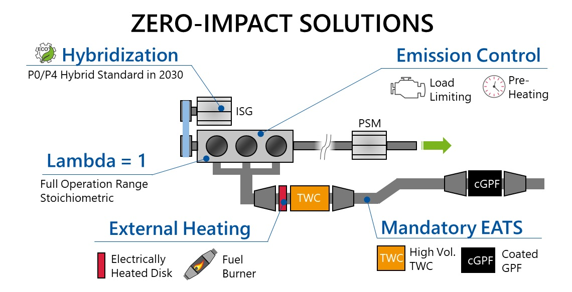
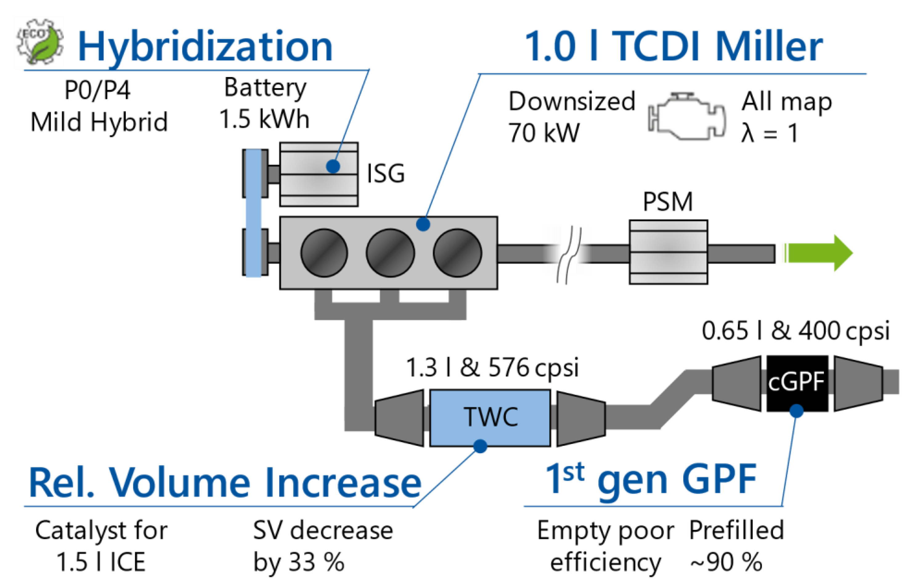
After the EU6 base model is set up with the methodology and benchmark described in Section 3, base technologies are added, as depicted in Figure 8, that are either mandatory or expected to be state-of-the-art in 2030+.
In a first step, emission features are implemented that are expected to be mandatory to achieve any emission legislation in 2030+. This includes the implementation of a gasoline particulate filter (GPF) with a filtration efficiency of 90%, integrated in the underfloor (UF) with a catalytic coating (four-way catalyst). The coated GPF (cGPF) is prefilled with soot and ash, which increases the filtration efficiency significantly [26]. While full-load enrichment is tolerated in EU6 legislation as an auxiliary emission strategy, this will probably change for upcoming legislative steps, as operations including high-load constant driving (e.g., trailer operation with high gradients) should be included [10,11]. Therefore, the engine must be operated with a stoichiometric air/fuel ratio in the whole operation range. Technology options to enable this such as integrated exhaust manifold or high temperature turbines are discussed in detail in [19]. With the European green deal and the resulting CO₂ reductions agreed in the Fit for 55 package [50], the reduction in fuel consumption is expected to be particularly focused on the high-volume C-segment. Therefore, the engine is downsized to 1.0 l and a P0/P4 mild hybridization is added.
4.2. Advanced Cold Emission Reduction
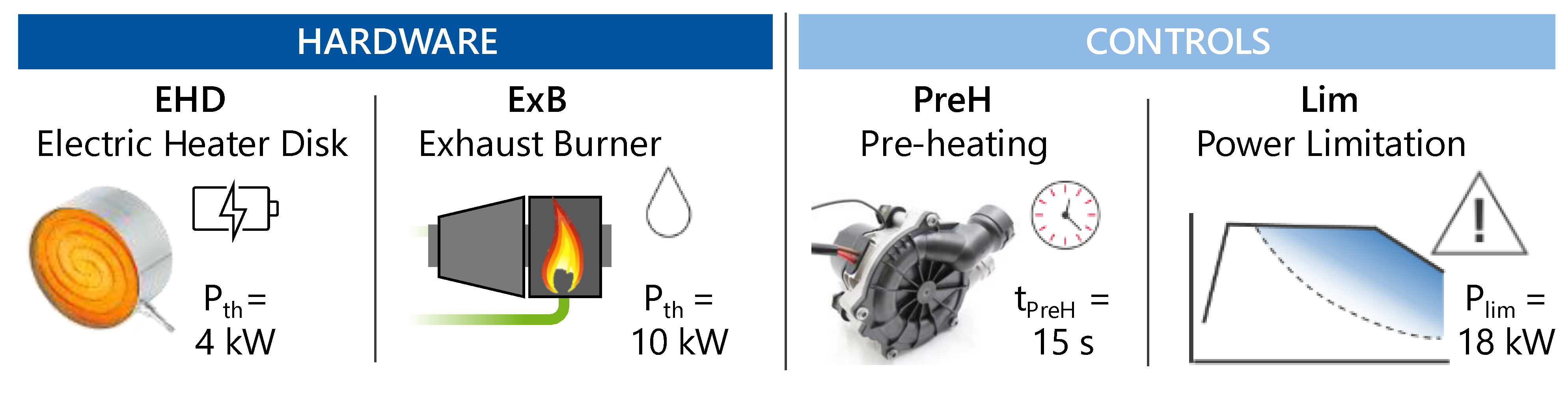
For gasoline powertrains, tailpipe emissions mainly occur at the cold start and warm up, since the catalytic converter has not reached its light-off temperature yet [51,52]. Additionally, this effect is aggravated for cold ambient conditions. Emissions have been shown to increase by a factor of 10 when decreasing the temperature from +30 °C to −7 °C [53]. As changes in the engine operation parameters such as late ignition and multiple injection are already exhausted for Euro 6 applications, additional measures that are more effective and cause less of a fuel penalty are focused upon for further emission reductions. The hardware and control measures that are investigated in this paper are shown in Figure 9.
A major trend in future emission reduction is the installation of an additional heating device such as an electric heater or additional fuel burner [29]. Electrical heating is typically applied by introducing an electrical heater disk (EHD) in front of the catalyst, either as a self-supporting structure [54] or coupled to a small TWC support brick [28,55]. The exhaust fuel burner (ExB) uses the thermal energy of a separate combustion to heat up the exhaust system directly. Other than the EHD, only auxiliary electrical energy is needed and is therefore mainly independent of the vehicle electrification. A 12 V bord net is sufficient to power the low-pressure fuel pump, secondary air, injection and ignition of the burner system. For a 20 s operation at 13 kW, about 0.007 l gasoline is needed [56]. However, since fuel is burned, raw emissions occur during operation while the catalyst is still cold and are therefore not converted [30,56]. For example, the applied burner emits 4.5 mg HC, 30.6 mg CO and 7.1 mg NOX in 15 s of operation.
Besides hardware measures, new emission control strategies can be introduced to reduce emissions at the cold start. By operating the additional heaters before the engine starts (pre-heating), the emissions can be reduced even further [30,31]. This must either be completed while the vehicle is stationary before driving or during an all-electric start and propulsion of the vehicle. In case of the first option (halt pre-heating), the customer acceptance is questionable, but might be suitable for price-sensitive vehicles or commercial applications. The second option (electrical pre-heating) is mainly investigated in combination with PHEVs, as the electrical system can propel the vehicle during EATS heat-up [19]. By combining the heating strategy with predictive route information, further synergies are possible [57]. For the electrical heater disk (EHD), an additional secondary air pump is necessary to transfer the generated heat via a convective mass flow downstream to the main catalyst. As the fuel burner system already includes a secondary air pump, it can be operated independently.
Another control measure is reducing the power output of the ICE during cold catalyst to avoid high raw emission mass flow and high space velocities before the light-off. If a hybrid system is installed, the electrical machine can propel the vehicle instead. For conventional powertrains or depleted battery, the driver will experience a drawback in vehicle performance that needs to be displayed, e.g., as a cold temperature warning.
Based on the hybrid electric vehicle (HEV) for 2030+, the technical measures are combined. The two heating measures EHD and ExB are investigated individually and combined with the power limitation (Lim), pre-heating (PreH), and both control measures.
5. Results
5.1. Euro 7 Scenario
5.1.1. Electrical Heater Disk—EHD
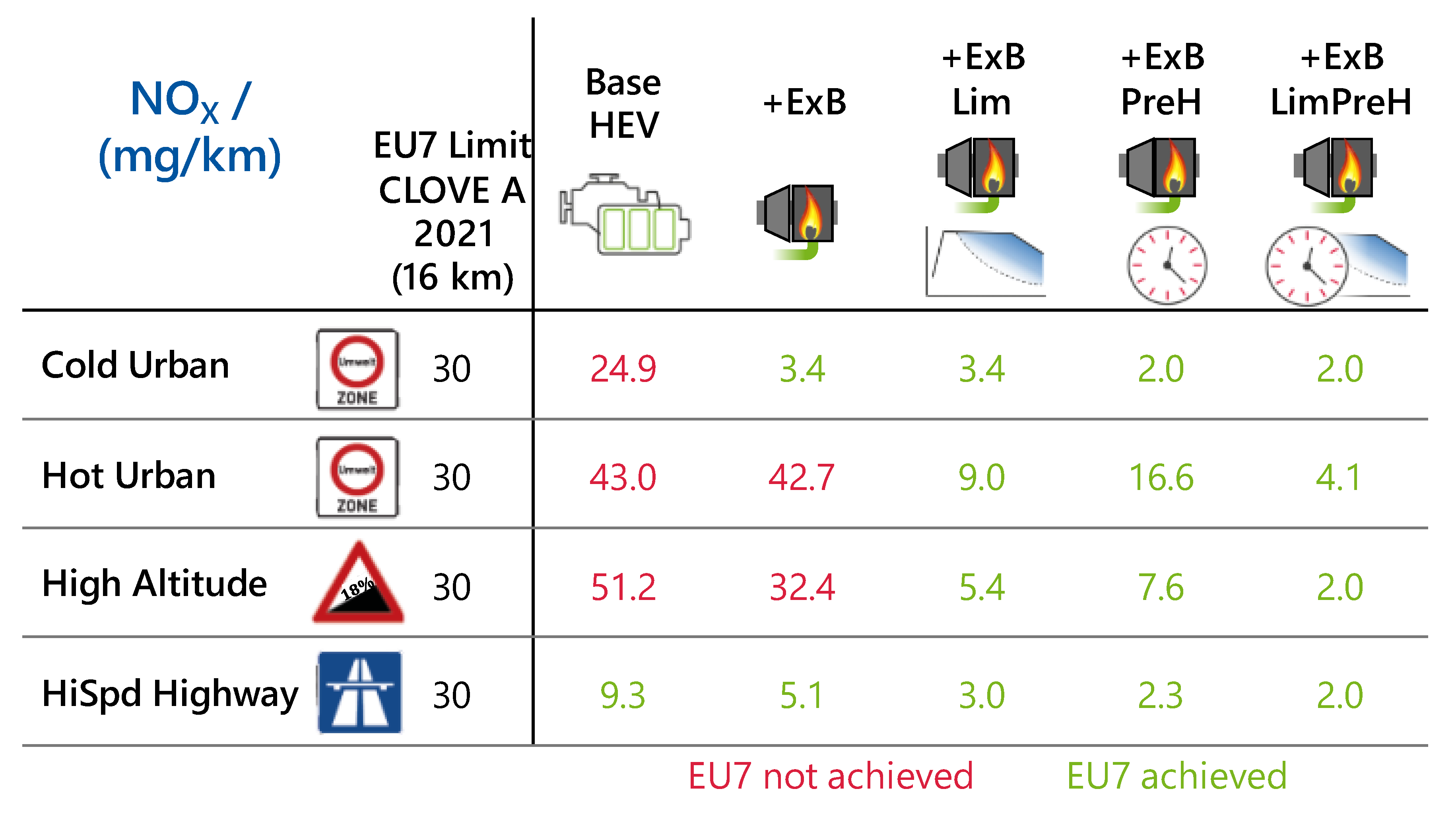
The variants with an EHD are investigated first. The results for the four challenging Euro 7 scenarios are shown in Figure 10.
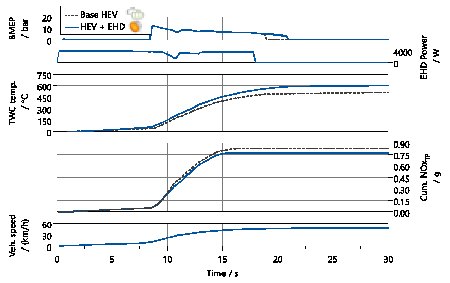
The Cold Urban and HiSpd Highway cycles are already achieved with the 2030 vehicle in the HEV configuration. On the other hand, the Hot Urban and High Altitude cycles are above the target limit for HEV, EHD and EHD PreH. Without power limitation, the EHD seems to be unable to achieve Euro 7 compliance in these cycles. Figure 11 shows the first part of the Hot Urban cycle for the HEV and EHD technology options.
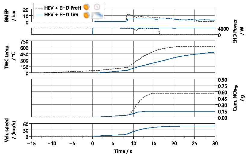
The cycle is characterized by an acceleration with high ICE load demand up to BMEP = 12 bar, starting from t = 8 s. The electrical heating does not increase the temperature fast enough to effectively heat up the exhaust gas and TWC. The benefit of adding an EHD is therefore minor. In the case of an even earlier or more intense acceleration, the EHD can also increase tailpipe emissions, as the additional thermal inertia of the disk slows the heat-up of the catalyst. This is the case for the Hot Urban cycle. To exploit the full potential of the EHD, the heating needs to be operated for some time before a high raw emission mass flow. This is possible by either operating the EHD before the ICE start (pre-heating) or by limiting the ICE power and thus the incoming raw emission mass flow. Both options are combined with the EHD in Figure 12.
The EHD is operated for 15 s before the start of the cycle for the pre-heating option. When the high acceleration of the cycle starts, the temperature is already at about TTWC = 150 °C. However, this is not sufficient to convert the high raw emissions in the first acceleration. Compared to the EHD (52.8 mg/km), the emissions are only reduced by about 26% with pre-heating (39.1 mg/km). For emission compliance, a longer pre-heating time would be necessary.
Alternatively, the power output of the ICE can be limited. This decreases raw emissions during low catalyst temperature and conversion efficiency. Therefore, a lower amount of tailpipe pollutants is emitted. On the other hand, the exhaust system is also heated up more slowly, as the exhaust enthalpy flow of the ICE is lower. Nevertheless, this phase of reduced emissions gives the EHD sufficient time to heat up the catalyst. Additionally, the necessary temperature needed for conversion is smaller at lower mass flows, as the conversion capability correlates with the space velocity of the exhaust gas. If the first few inches of the catalyst are sufficiently heated, this is enough for a small emission mass flow. Hence, the EHD Lim in Figure 12 is already effectively converting the NOX emissions at about t = 15 s, even though the whole catalyst has only reached an average temperature of TTWC = 250 °C.
In conclusion, the Euro 7 cycles that are the most challenging are characterized by high load during the cold start phase. A pre-heating time of 15 s is not enough to prepare the EATS system for high-emission mass flows. Limiting the ICE power is an effective measure that counters this challenge directly, and thus achieves the NOX limits in combination with the EHD. The same is true for HC emissions in the High Altitude scenario, where CO emissions are achieved with all technology options (see Appendix A for detailed HC and CO results).
5.1.2. Exhaust Gas Burner—ExB
The results of the exhaust gas burner under Euro 7 conditions are presented in Figure 13.
As for the EHD, the Cold Urban and HiSpd Highway cycles are achieved with all variants. However, the emission results are very low with the exhaust burner and can even reach 2.0 mg/km NOX when combined with pre-heating. If the exhaust burner is operated without pre-heating, the emissions benefit is lower in the Hot Urban and High Altitude scenarios. This is again due to interactions with the first acceleration phase: while the ExB yields a slightly increased catalyst temperature (+90 K), the overall mass flow and therefore the space velocity is about 20% higher. This partly neglects the benefit from the higher temperature. With a sophisticated emission control strategy, the burner operation could be reduced depending on the exhaust mass flow, thus avoiding the increase in the space velocity. This is an imminent difference to the EHD, which cannot be removed flexibly from the exhaust system and thus can always lead to drawbacks due to the thermal inertia.
Similar to the EHD, the limitation of the ICE power shows the most significant benefit for the two critical cycles. The effects are the same as those shown in Figure 12, except for the burner operating with a higher heating power and therefore with decreased heating time.
In summary, the exhaust burner shows a similar performance in the Euro 7 scenarios compared to the EHD (CO and HC are found in the Appendix A). For the compliant cases, the ExB achieves a much lower volume of pollutant emissions, demonstrating the benefit of the increased heating power. While overachieving the targets of Euro 7 is not necessary, this shows the potential of the burner for more strict conditions such as the Zero-Impact Emissions concept.
5.2. Zero-Impact Emissions
5.2.1. Electrical Heater Disk—EHD
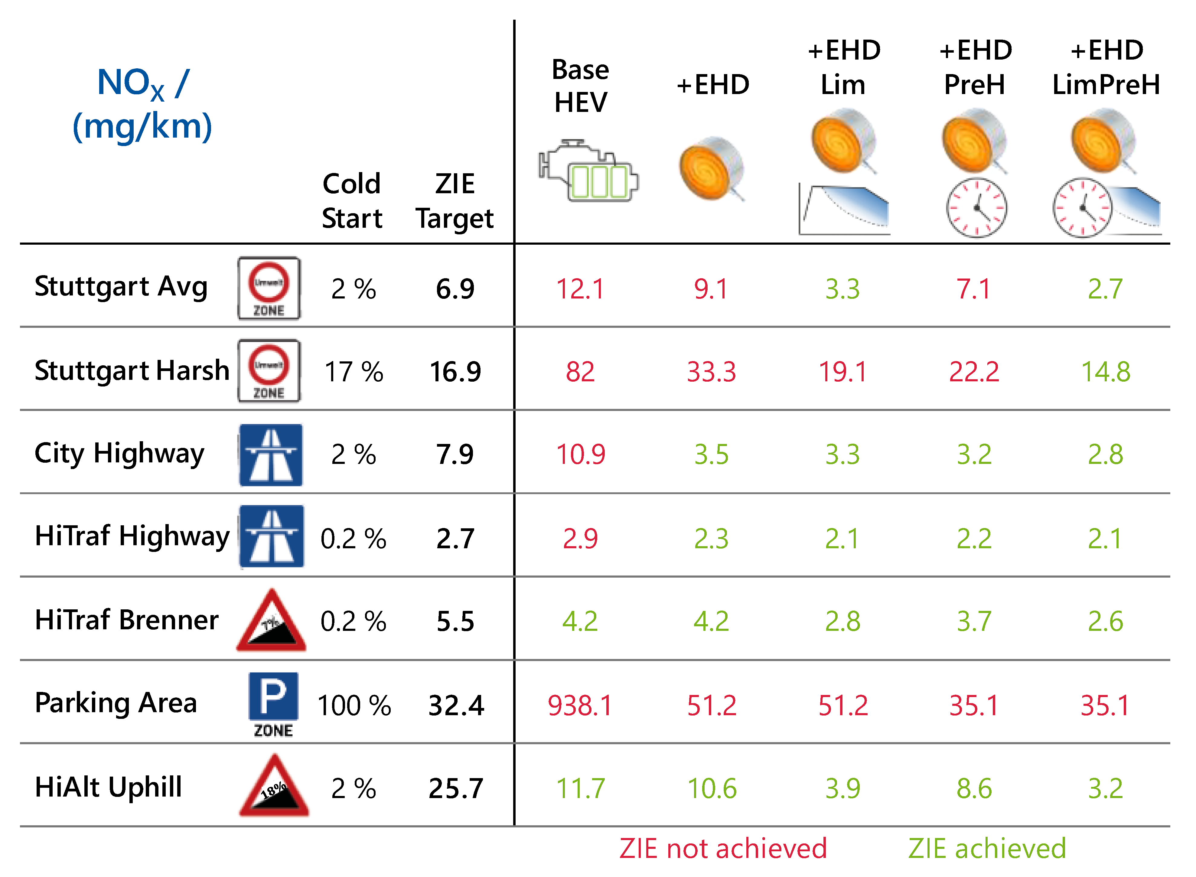
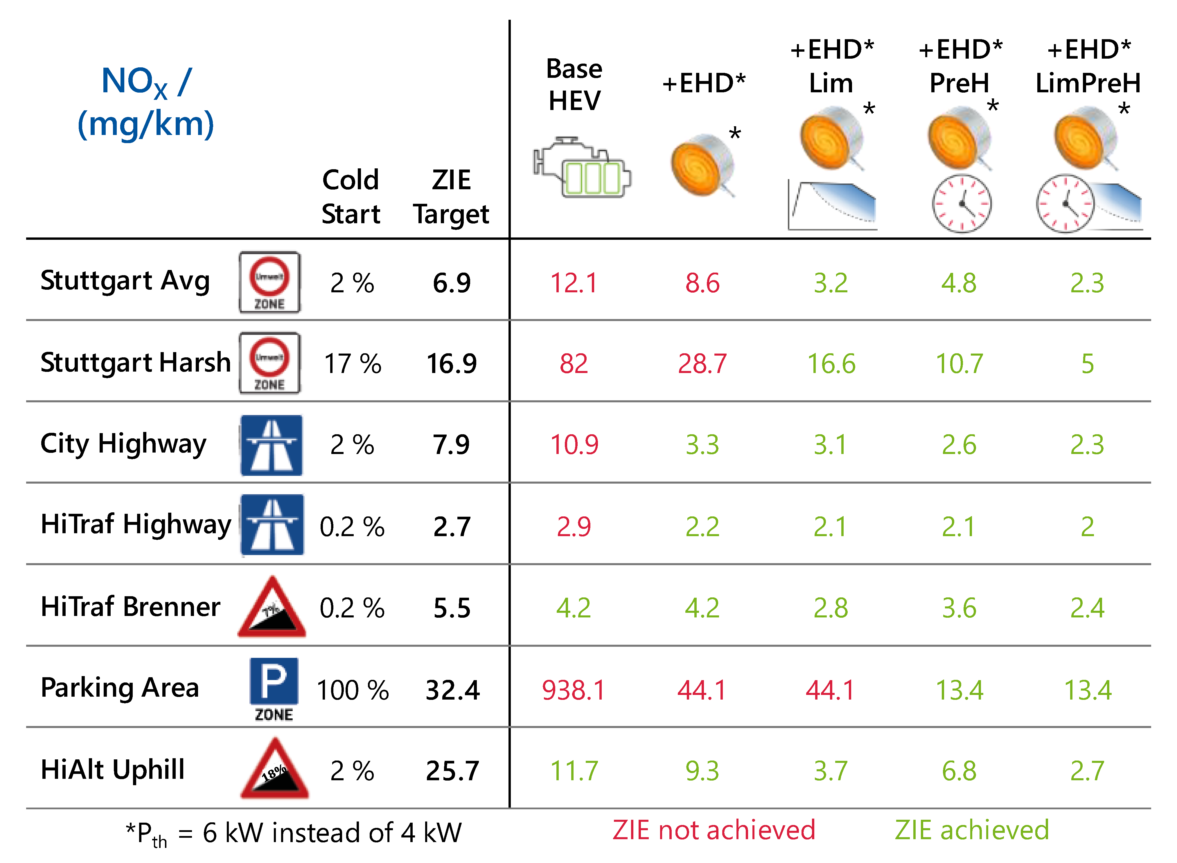
Figure 14 shows the results of the EHD technology packages for the Zero-Impact Emissions scenarios.
The base technologies implemented for the 2030 vehicle, especially the relatively increased catalyst volume, already convert emissions very effectively in warm conditions, leading to results of <2 mg/km after the cold start. As the Brenner and Uphill scenarios both have quite high ZIE targets and low cold start shares, the measures are already sufficient to achieve Zero-Impact Emissions. On the other hand, for scenarios with high cold start share such as the worst-case Stuttgart or even the Parking Area, the base HEV emits significantly more emissions. Adding an EHD reduces the emissions drastically in the cold start, resulting, e.g., in a 94% reduction for the Parking Area scenario. All Highway scenarios are achieved with the introduction of the EHD alone. However, to achieve the urban scenarios with high cold start share, emissions must be reduced even further. Limiting the power is very effective for the scenarios with high dynamic operation (e.g., Stuttgart WC), but shows no effect for the Parking Area, as the power requirements are below the limitation already. On the other hand, 15 s of pre-heating reduces the emissions for every scenario; however, the effect is too low for a further drastic reduction. By combining both measures, all scenarios except for the Parking Area are achieved. Since the power limitation does not have any effect on the later scenario, a higher heating power (e.g., by installing an additional EHD) or more pre-heating time is needed. Figure 15 shows a variation of the pre-heating time for the Parking Area scenario.
The raw emissions that occur depend on the cycle load profile and the emission conversion in the TWC increases rapidly around the light-off temperature. Hence, while the increase in the TWC temperature is directly proportional to the pre-heating time, the reduction in emissions is not. The investigated variants EHD and EHD PreH are highlighted. It is clear that both are insufficient to achieve the ZIE target. However, in increasing the pre-heating time by only 5 s, the EHD is able to achieve this scenario with a total of 20 s of pre-heating. On the other hand, if the boundary conditions are less challenging, e.g., the ambient temperature is not −5 °C, but 20 °C, the pre-heating is more efficient, even though the raw NOX emissions are slightly increased. In the case of 20 °C, a pre-heating time of 15 s would already be sufficient to achieve Zero-Impact Emissions.
The increased heating performance of 48 V electrical heater systems has recently been investigated, e.g., with Pth = 6 kW [58,59]. This is an alternative possibility to decrease the necessity for pre-heating and hence achieve Zero-Impact Emissions under challenging conditions. Figure 16 shows the results for an electrical heater disk with this increased heating power (EHD*) under Zero-Impact test scenarios.
With the increased heating power, the emissions are further reduced in all cycles. In summary, the EHD is able to achieve all Zero-Impact Emissions scenarios when combining both power limitation and pre-heating. For the large parking area, a minor adaption to the pre-heating time is necessary or the heating power needs to be increased. On the other hand, this scenario is very exotic (assuming all cars in a parking lot start at the same time in winter, e.g., after a music concert) and is mainly used for checking all possible conditions. The urban and highway cases are much more relevant for clean air quality in the real world, since they occur more frequently. Installing different hardware might not be reasonable, if it is only needed for a single worst-case scenario that will probably never occur in real-world driving. For more common cases, e.g., an ambient temperature of 20 °C instead of −5 °C, additional measures are again not needed.
5.2.2. Exhaust Gas Burner—ExB
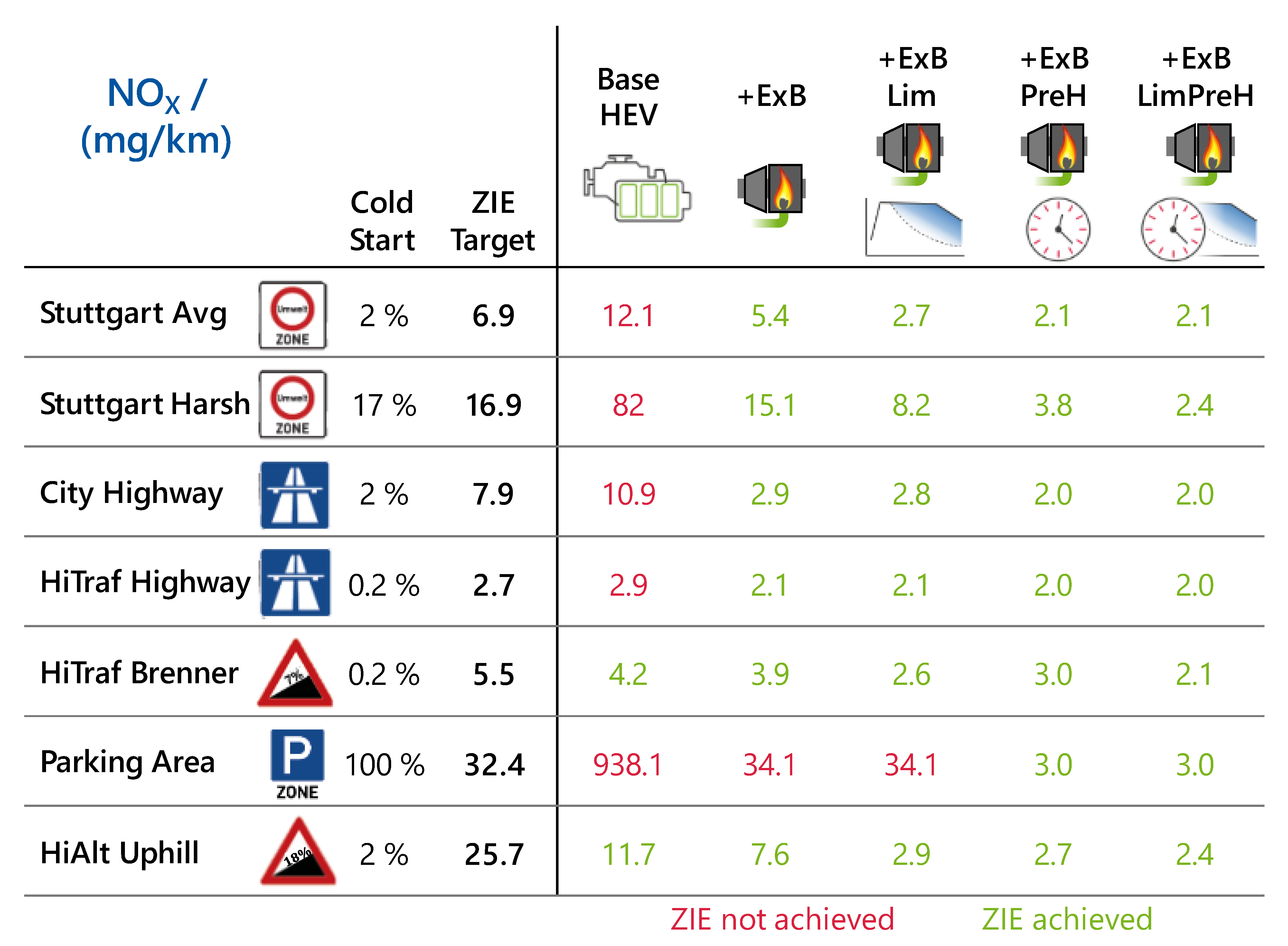
Figure 17 shows the results for the ExB technology packages under Zero-Impact Emissions test conditions.
Since the exhaust burner has a heating power of PExB = 10 kW instead of only PEHD = 4 kW for the EHD, the emission reduction is much more significant when only adding the burner. Compared to the EHD performance in Figure 14, the burner additionally reduces emissions up to 55% (Stuttgart WC). Without additional control measures, the exhaust burner is already able to achieve all scenarios except for the Parking Area. This demonstrates the high impact of the heating power. The additional pollutant emissions of the ExB are negligible compared to the benefit of the additional exothermal output. To achieve the Parking Area scenario, an additional pre-heating time is necessary. With the 15 s implemented in the ExB PreH option, the emission factor is already 90% below the ZIE target. A minor pre-heating time, e.g., of 5 s, would already be sufficient here.
6. Conclusions
For both Euro 7 and Zero-Impact Emissions, mandatory technologies must be implemented in a gasoline passenger car. Most importantly, when using a three-way catalyst, the engine must be operated stoichiometrically in the full operation range and the relative size of the catalyst must be increased compared to the installed combustion engine power and therefore maximum mass flow. While this base vehicle might achieve very low emissions under normal driving and ambient conditions, additional measures are necessary for the challenging conditions that are tested for under Euro 7 and Zero-Impact Emissions scenarios. Cold start emissions must be reduced with additional exhaust heating. A 4 kW electrical heater disc can manage even the harshest conditions for the Euro 7 scenario, when the accessible power of the engine is limited to 25% of nominal power while the average catalyst temperature is below 400 °C. The NOX results range from 3.5 to 11.4 mg/km. For Zero-Impact, further reduction is necessary. This can be achieved by adding a pre-heating time of 15 s to the power limitation, accomplishing NOX emission factors down to 2.7 mg/km. The drawbacks in terms of the customer value of a vehicle that is limited at such conditions could be tolerated, as high engine power demand in the first ~30 s scarcely occurs.
Alternatively, an exhaust burner can achieve both Euro 7 and Zero-Impact scenarios with pre-heating alone, with NOX emission factors down to 2.0 mg/km. An additional reduction in power can reduce emissions even further, but this is not needed for Euro 7 and Zero-Impact. This is due to the largely increased heating power of 10 kW. Additional fuel consumption and pollutant emissions for the operation of the burner are minor. However, broad acceptance of a Zero-Impact technology might be more easily achieved with electrical heating that is temporarily pollutant-free, even though the overall emissions might be higher than with an exhaust burner.
While the requirements to achieve Zero-Impact are somewhat higher, there are no additional hardware changes needed based on the Euro 7 layout. Adaptions to the vehicle controls are sufficient. Hence, the remaining gap between Euro 7 and Zero-Impact Emissions is minor for gasoline vehicles: the harsh Euro 7 scenario with 30 mg/km NOX limit already ensures a vehicle that could be branded as Zero-Impact for the air quality in most of the investigated cases. This also means that Euro 7 is well suited to achieve its major target: achieving clean air under real-world conditions.
Finally, this paper investigated the technical requirements to achieve Zero-Impact Emissions under the most challenging conditions. However, the tested scenarios, such as peak traffic in winter with unfavorable air dilution, are not representative of average situations. Most probably, the harsh measures needed for the extreme scenarios are not necessary in most driving situations. In future investigations, a cost–benefit analysis could be conducted that assesses the occurrence of the scenarios and identifies the concepts that achieve Zero-Impact Emissions with reasonable additional emission measures.
Author Contributions
Conceptualization, R.M. and T.K.; funding acquisition, R.M.; methodology, R.M. and T.K.; project administration, M.G.; resources, M.G.; supervision, S.P.; visualization, R.M.; writing—original draft, R.M.; writing—review and editing, S.S. and M.G. All authors have read and agreed to the published version of the manuscript.
Funding
This research was funded by FVV e.V., project number 1412.
Institutional Review Board Statement
Not applicable.
Informed Consent Statement
Not applicable.
Data Availability Statement
Data are partly available on request from the corresponding author with the permission of the Research Association for Combustion Engines and their members. The Zero-Impact Emission test scenarios are publicly available.
Acknowledgments
The authors would like to thank Frank Bunar (IAV GmbH) and the FVV working group for the great discussions, ideas and support while conducting the corresponding research project. Many thanks also go to Lukas Dahmann and Phillip Hogrebe for their contribution to this paper.
Conflicts of Interest
The authors declare no conflict of interest. The funders agreed to publish the results and gave constructive feedback on the study design, data analyses and interpretation.
Appendix A. Euro 7 Results for HC and CO
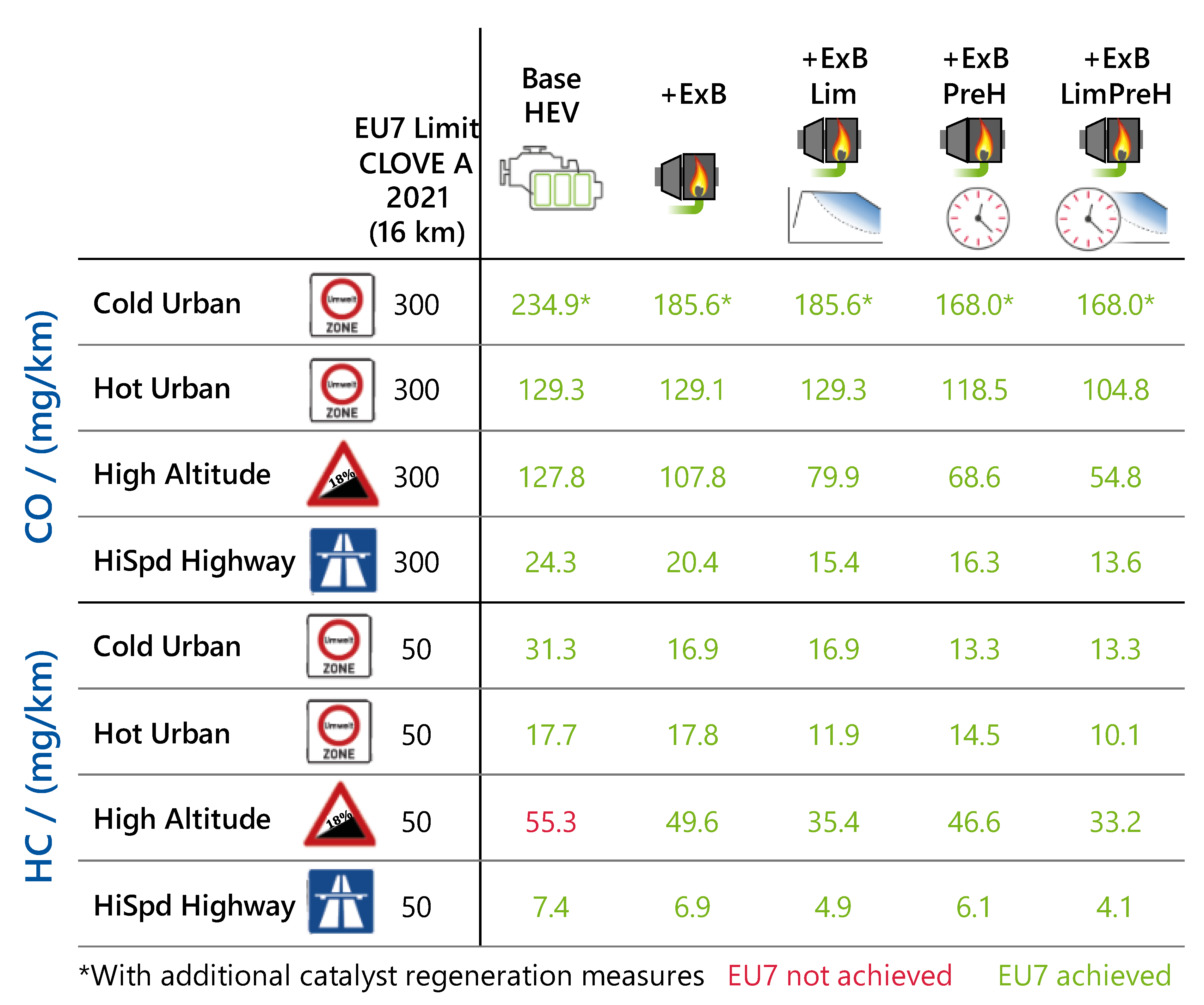
The HC and CO emissions were also investigated in detail in the corresponding FVV project “Zero-Impact Tailpipe Emissions”. The following Figure A1 and Figure A2 show the global results for the investigated cycles and both the EHD and ExB.
Figure A1.
Electrical heater disk technology results for CO and HC in the Euro 7 scenarios.

Figure A2.
Exhaust burner technology results for CO and HC in the Euro 7 scenarios.

The analyses showed that NOX is the most critical to achieve, hence the focus of the paper. For CO emissions, adaptions of the catalyst regeneration strategy were necessary in the Cold Urban cycle due to very frequent changes in the ICE load. For a CO-critical layout, it is beneficial to avoid catalyst regeneration completely, e.g., by shutting off the exhaust valves during ICE stalling or shut-off. Possible technologies and their benefits are discussed in the recent literature [60,61].
Appendix B. Cycle Profiles
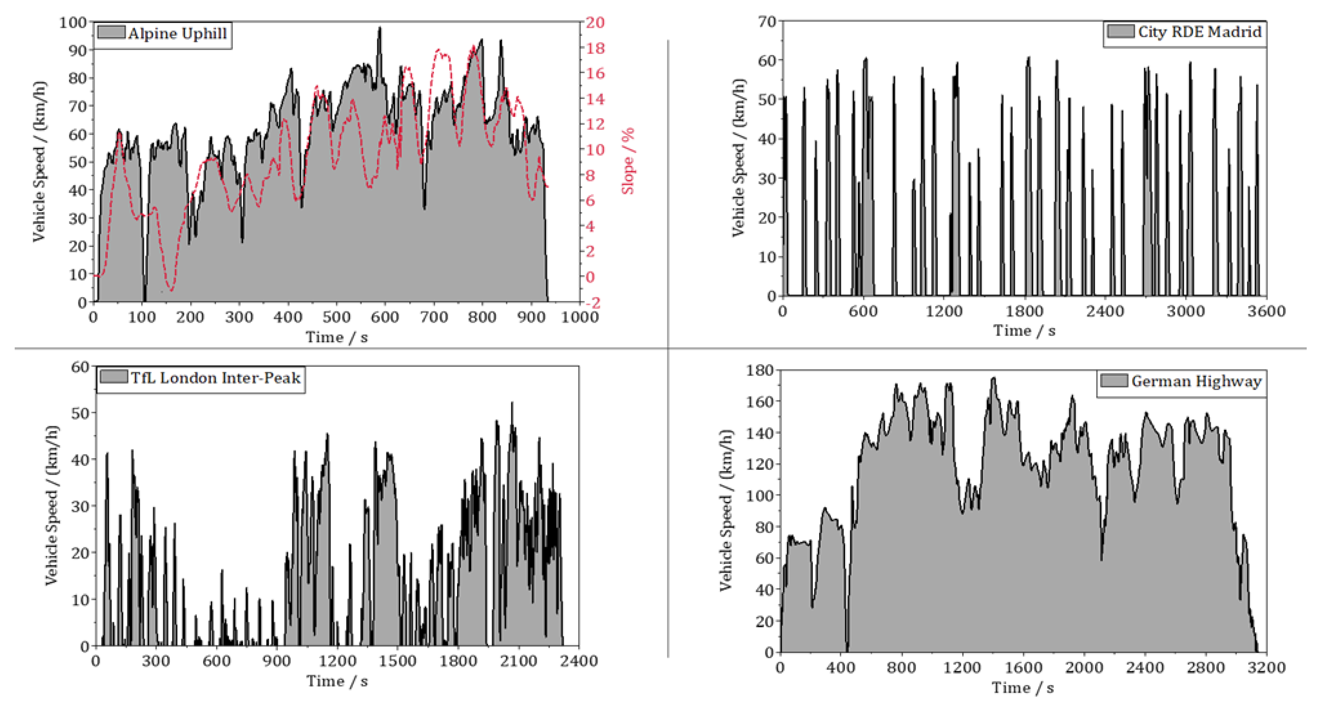
The cycle profiles for the Zero-Impact Emission scenarios are described in detail in [17], and the cycle data are publicly available [45]. The duty cycles for the Euro 7 scenarios are shown in Figure A3.
Figure A3.
Driving profiles for the Euro 7 scenarios.

References
- Reitz, R.D.; Ogawa, H.; Payri, R.; Fansler, T.; Kokjohn, S.; Moriyoshi, Y.; Agarwal, A.K.; Arcoumanis, D.; Assanis, D.; Bae, C.; et al. IJER editorial: The future of the internal combustion engine. Int. J. Engine Res. 2020, 21, 3–10. [Google Scholar] [CrossRef]
- North, R.J.; Ochieng, W.Y.; Quddus, M.A.; Noland, R.B.; Polak, J.W. Development of a vehicle emissions monitoring system. Proc. Inst. Civ. Eng. Transp. 2005, 158, 167–177. [Google Scholar] [CrossRef]
- Fontaras, G.; Zacharof, N.-G.; Ciuffo, B. Fuel consumption and CO2 emissions from passenger cars in Europe—Laboratory versus real-world emissions. Prog. Energy Combust. Sci. 2017, 60, 97–131. [Google Scholar] [CrossRef]
- Dimaratos, A.; Toumasatos, Z.; Doulgeris, S.; Triantafyllopoulos, G.; Kontses, A.; Samaras, Z. Assessment of CO2 and NOx emissions of one diesel and one bi-fuel gasoline/CNG euro 6 vehicles during real-world driving and laboratory testing. Front. Mech. Eng. 2019, 5, 62. [Google Scholar] [CrossRef]
- Simonen, P.; Kalliokoski, J.; Karjalainen, P.; Rönkkö, T.; Timonen, H.; Saarikoski, S.; Aurela, M.; Bloss, M.; Triantafyllopoulos, G.; Kontses, A.; et al. Characterization of laboratory and real driving emissions of individual Euro 6 light-duty vehicles—Fresh particles and secondary aerosol formation. Environ. Pollut. 2019, 255, 113175. [Google Scholar] [CrossRef]
- Claßen, J.; Krysmon, S.; Dorscheidt, F.; Sterlepper, S.; Pischinger, S. Real driving emission calibration—Review of current validation methods against the background of future emission legislation. Appl. Sci. 2021, 11, 5429. [Google Scholar] [CrossRef]
- Toenges-Schuller, N.; Schneider, C.; Niederau, A.; Vogt, R.; Hausberger, S. Modelling the effect on air quality of Euro 6 emission factor scenarios. J. Earth Sci. Geotech. Eng. 2016, 6, 227–244. [Google Scholar]
- de Meij, A.; Astorga, C.; Thunis, P.; Crippa, M.; Guizzardi, D.; Pisoni, E.; Valverde, V.; Suarez-Bertoa, R.; Oreggioni, G.D.; Mahiques, O.; et al. Modelling the impact of the introduction of the EURO 6d-TEMP/6d regulation for light-duty vehicles on EU air quality. Appl. Sci. 2022, 12, 4257. [Google Scholar] [CrossRef]
- Hata, H.; Okada, M.; Yanai, K.; Kugata, M.; Hoshi, J. Exhaust emissions from gasoline vehicles after parking events evaluated by chassis dynamometer experiment and chemical kinetic model of three-way catalytic converter. Sci. Total Environ. 2022, 848, 157578. [Google Scholar] [CrossRef]
- Samaras, Z.; Balazs, A.; Ehrly, M.; Kontses, A.; Dimaratos, A.; Kontses, D.; Aakko, P.; Ligterink, N.; Andersson, J.; Scarbarough, T.; et al. Preliminary findings on possible Euro 7 emission limits for passenger cars and LCVs. In Proceedings of the Online AGVES Meeting, Online, 8 April 2021. [Google Scholar]
- Samaras, Z.; Hausberger, S.; Mellios, G. Preliminary findings on possible Euro 7 emission limits for LD and HD vehicles. In Proceedings of the Online AGVES Meeting, Online, 27 October 2020. [Google Scholar]
- Raju, A.S.; Wallerstein, B.R.; Johnson, K.C. Achieving NOx and Greenhouse gas emissions goals in California’s Heavy-Duty transportation sector. Transp. Res. Part D Transp. Environ. 2021, 97, 102881. [Google Scholar] [CrossRef]
- The California Low-Emission Vehicle Regulations: CARB. 2022.
- Eichlseder, H.; Hausberger, S.; Sturm, P. The zero impact combustion engine—A vision? In Proceedings of the 32nd International AVL Conference “Engine & Environment”, Graz, Austria, 25–29 May 2020. [Google Scholar]
- Eichlseder, H.; Hausberger, S.; Beidl, C.; Steinhaus, T. Zero impact—Objective and significance for vehicle powertrains and air quality. In Internationaler Motorenkongress 2021; Liebl, J., Beidl, C., Maus, W., Eds.; MORGAN KAUFMANN: Burlington, MA, USA, 2021; pp. 437–451. ISBN 978-3-658-35587-6. [Google Scholar]
- Hausberger, S.; Urner, U.; Toenges-Schuller, N.; Stadlhofer, W.; Schneider, C. Zero-Impact Vehicle Emissions—Final Report; FVV e.V.: Frankfurt, Germany.
- Maurer, R.; Kossioris, T.; Hausberger, S.; Toenges-Schuller, N.; Sterlepper, S.; Günther, M.; Pischinger, S. How to define and achieve zero-impact emissions in road transport? Transp. Res. Part D Transp. Environ. 2023, 12, 275–280. [Google Scholar] [CrossRef]
- List, H.; Fischer, R. Zero-impact mobility. Emissions and lifecycle CO2: No longer a conflict? In Proceedings of the 32nd International AVL Conference “Engine & Environment”, Graz, Austria, 25–29 May 2020. [Google Scholar]
- Maurer, R.; Yadla, S.K.; Balazs, A.; Thewes, M.; Walter, V.; Uhlmann, T. Designing zero impact emission vehicle concepts. In Experten-Forum Powertrain: Ladungswechsel und Emissionierung 2020; Liebl, J., Ed.; Springer: Berlin/Heidelberg, Germany, 2021; pp. 75–116. ISBN 978-3-662-63523-0. [Google Scholar]
- García-Contreras, R.; Soriano, J.A.; Fernández-Yáñez, P.; Sánchez-Rodríguez, L.; Mata, C.; Gómez, A.; Armas, O.; Cárdenas, M.D. Impact of regulated pollutant emissions of Euro 6d-Temp light-duty diesel vehicles under real driving conditions. J. Clean. Prod. 2021, 286, 124927. [Google Scholar] [CrossRef]
- Ntziachristos, L.; Papadimitriou, G.; Ligterink, N.; Hausberger, S. Implications of diesel emissions control failures to emission factors and road transport NOx evolution. Atmos. Environ. 2016, 141, 542–551. [Google Scholar] [CrossRef]
- Zacharof, N.; Tietge, U.; Franco, V.; Mock, P. Type approval and real-world CO2 and NOx emissions from EU light commercial vehicles. Energy Policy 2016, 97, 540–548. [Google Scholar] [CrossRef]
- Wang, J.; Wang, R.; Yin, H.; Wang, Y.; Wang, H.; He, C.; Liang, J.; He, D.; Yin, H.; He, K. Assessing Heavy-Duty Vehicles (HDVs) on-road NOx emission in China from On-Board Diagnostics (OBD) remote report data. Sci. Total Environ. 2022, 846, 157209. [Google Scholar] [CrossRef]
- Zhang, W.; Lu, J.; Xu, P.; Zhang, Y. Moving towards sustainability: Road grades and on-road emissions of heavy-duty vehicles—A case study. Sustainability 2015, 7, 12644–12671. [Google Scholar] [CrossRef]
- Papetti, V.; Dimopoulos Eggenschwiler, P.; Emmanouil, V.; Koltsakis, G. Analysis of TWC characteristics in a Euro6 gasoline light duty vehicle. In Proceedings of the 14th International Conference on Engines & Vehicles; SAE Technical Paper Series; Warrendale, PA, USA, 15–19 September 2019; SAE International400 Commonwealth Drive: Warrendale, PA, USA, 2019. [Google Scholar]
- Rose, D. New Generation Gasoline Particulate Filters for Uncatalyzed Applications and Lowest Particulate Emissions. In Proceedings of the 12th International VERT FORUM, eConference. 24 March 2022. [Google Scholar]
- Association for Emissions Control by Catalyst. Gasoline Particle Filter: How Can the GPF Cut Emissions of Ultrafine Particles from Gasoline Engines? 2017. Available online: https://www.aecc.eu/wp-content/uploads/2020/08/2017-AECC-technical-summary-on-GPF-final.pdf (accessed on 3 February 2023).
- Maus, W.; Brück, R.; Konieczny, R.; Scheeder, A. Electrically heated catalyst for thermal management in modern vehicle applications. MTZ Worldw. 2010, 71, 34–39. [Google Scholar] [CrossRef]
- Gao, J.; Tian, G.; Sorniotti, A.; Karci, A.E.; Di Palo, R. Review of thermal management of catalytic converters to decrease engine emissions during cold start and warm up. Appl. Therm. Eng. 2019, 147, 177–187. [Google Scholar] [CrossRef]
- Cucchi, M.; Medda, M.; Paltrinieri, S.; Rossi, V.; Rulli, F.; Tonelli, R. Active heating devices to reduce cold start emissions in sport cars. In Proceedings of the 43rd International Vienna Motor Symposium, Vienna, Austria, 27–29 April 2022; p. 32, ISBN 978-3-9504969-1-8. [Google Scholar]
- Vilwanathan Velmurugan, D.; McKelvey, T.; Olsson, J.-O. Data-driven near-optimal on-line control for an electrically heated catalyst-equipped gasoline engine. SAE Int. J. Engines 2023, 16, 03-16-03-0019. [Google Scholar] [CrossRef]
- Baumgarten, H.; Scharf, J.; Thewes, M.; Uhlmann, T.; Balazs, A.; Böhmer, M. Simulation-Based Development Methodology for Future Emission Legislation. In Proceedings of the 37th Internationales Wiener Motorensymposium, Vienna, Austria, 28–29 April 2016; pp. 209–231, ISBN 9783186799128. [Google Scholar]
- Böhmer, M. Marius Böhmer. Simulation of Exhaust Emissions for Hybrid Vehicles Considering Real Driving Conditions. Ph.D. Thesis, RWTH Aachen, Aachen, Germany, 2017. [Google Scholar]
- DiGiulio, C.D.; Pihl, J.A.; Parks, J.E., II; Amiridis, M.D.; Toops, T.J. Passive-ammonia Selective Catalytic Reduction (SCR): Understanding NH3 formation over close-coupled Three Way Catalysts (TWC). Catal. Today 2014, 231, 33–45. [Google Scholar] [CrossRef]
- Hoekman, S.K. Review of nitrous oxide (N2O) emissions from motor vehicles. SAE Int. J. Fuels Lubr. 2020, 13, 79–98. [Google Scholar] [CrossRef] [PubMed]
- Yan, Y.; Liu, Z.; Liu, J. An evaluation of the conversion of gasoline and natural gas spark ignition engines to ammonia/hydrogen operation from the perspective of laminar flame speed. J. Energy Resour. Technol. 2023, 145, 012302. [Google Scholar] [CrossRef]
- The International Council on Clean Transportation. Driving Resistances of Light-Duty Vehicles in Europe: Present Situation, Trends and Scenarios for 2025; The International Council on Clean Transportation: Berlin, Germany, 2016. [Google Scholar]
- Uhlmann, T.; Alt, N.; Thewes, M.; Lückmann, D.; Balazs, A.; Maurer, R.; Sahr, C.; Kürten, C.; Vosshall, T.; Müller, A. Hybrid BEV—A one platform solution for future passenger cars. In 30. Aachen Colloquium Sustainable Mobility; RWTH Aachen University: Aachen, Germany, 2021; ISBN 978-3-00-068207-0. [Google Scholar]
- Uhlmann, T.; Alt, N.; Lückmann, D.; Balazs, A.; Zwar, P.; Müller, A.; Thewes, M.; Frese, J. xHEV Konzept zur Erreichung der CO2-Ziele in 2030. In Proceedings of the 42nd International Vienna Motor Symposium, Vienna, Austria, 29–30 April 2021; ISBN 9783950496901. [Google Scholar]
- Proposal for a Regulation of the European Parliament and of the Council on Type-Approval of Motor Vehicles and Engines and of Systems, Components and Separate Technical Units Intended for Such Vehicles, with Respect to Their Emissions and Battery Durability (Euro 7) and Repealing Regulations (EC) No 715/2007 and (EC) No 595/2009. 2022. Available online: https://eur-lex.europa.eu/legal-content/EN/TXT/?uri=CELEX%3A52022PC0586 (accessed on 3 February 2023).
- Meng, Z.; Liu, Z.; Liu, J. Investigation of in-cylinder combustion deterioration of diesel engines in plateau regions. Fuel 2022, 324, 124824. [Google Scholar] [CrossRef]
- Kexel, J.; Müller, J.; Günther, M.; Pischinger, S.; Sens, M. HyFlex-ICE Intermediate Report; FVV e.V.: Frankfurt, Germany, 2022. [Google Scholar]
- Maurer, R.; Kossioris, T.; Sterlepper, S.; Günther, M.; Bunar, F. Zero-Impact Tailpipe Emissions: Final Report, Project no. 1412; FVV eV: Frankfurt, Germany, 2023. [Google Scholar]
- Hausberger, S.; Urner, U.; Toenges-Schuller, N.; Stadlhofer, W.; Schneider, C. Zero-Impact Vehicle Emissions— Interim Report 15.12.2020 t; FVV e.V.: Frankfurt, Germany, 2020. [Google Scholar]
- Kossioris, T.; Maurer, R. Zero-Impact Tailpipe Emissions—Test Cycles, Mendeley Data, V1. Available online: https://data.mendeley.com/datasets/z4kdp3k6dp/1 (accessed on 4 July 2022). [CrossRef]
- Tang, J.; McNabola, A.; Misstear, B.; Pilla, F.; Alam, M.S. Assessing the impact of vehicle speed limits and fleet composition on air quality near a school. Int. J. Environ. Res. Public Health 2019, 16, 149. [Google Scholar] [CrossRef] [PubMed]
- Coelho, M.C.; Farias, T.L.; Rouphail, N.M. Effect of roundabout operations on pollutant emissions. Transp. Res. Part D Transp. Environ. 2006, 11, 333–343. [Google Scholar] [CrossRef]
- Coelho, M.C.; Farias, T.L.; Rouphail, N.M. Impact of speed control traffic signals on pollutant emissions. Transp. Res. Part D Transp. Environ. 2005, 10, 323–340. [Google Scholar] [CrossRef]
- Coelho, M.C.; Frey, H.C.; Rouphail, N.M.; Zhai, H.; Pelkmans, L. Assessing methods for comparing emissions from gasoline and diesel light-duty vehicles based on microscale measurements. Transp. Res. Part D Transp. Environ. 2009, 14, 91–99. [Google Scholar] [CrossRef]
- Proposal for a Regulation of the European Parliament and of the Council Amending Regulation (EU) 2019/631. 2021. Available online: https://eur-lex.europa.eu/legal-content/en/TXT/?uri=CELEX%3A52021PC0556 (accessed on 3 February 2023).
- Zhu, G.; Liu, J.; Fu, J.; Xu, Z.; Guo, Q.; Zhao, H. Experimental study on combustion and emission characteristics of turbocharged gasoline direct injection (GDI) engine under cold start New European Driving Cycle (NEDC). Fuel 2018, 215, 272–284. [Google Scholar] [CrossRef]
- Mahadevan, G.; Subramanian, S. Experimental investigation of cold start emission using dynamic catalytic converter with pre-catalyst and hot air injector on a multi cylinder spark ignition engine; SAE Technical Paper Series. In Proceedings of the International Powertrains, Fuels & Lubricants Meeting, Beijing, China, 8 October 2017. [Google Scholar]
- Yusuf, A.A.; Inambao, F.L. Effect of cold start emissions from gasoline-fueled engines of light-duty vehicles at low and high ambient temperatures: Recent trends. Case Stud. Therm. Eng. 2019, 14, 100417. [Google Scholar] [CrossRef]
- Fricke, F.; Steinhuber, T.; Grußmann, E.; Rusche, U. Concept studies for electrically heated catalysts. MTZ Worldw. 2021, 82, 28–33. [Google Scholar] [CrossRef]
- Breuer, J.; Hirth, P.; Brück, R.; Kruse, C. Electrically heated catalyst for future USA and european legislation; SAE Technical Paper Series. In Proceedings of the International Congress & Exposition, Atlanta, Ga, USA, 1 February 1996; p. 1996. [Google Scholar]
- Öser, P.; Mueller, E.; Härtel, G.; Schürfeld, A. Novel emission technologies with emphasis on catalyst cold start improvements status report on VW-Pierburg Burner/Catalyst systems. SAE Trans. 1994, 103, 183–196. [Google Scholar]
- Canè, S.; Brunelli, L.; Gallian, S.; Perazzo, A.; Brusa, A.; Cavina, N. Performance assessment of a predictive pre-heating strategy for a hybrid electric vehicle equipped with an electrically heated catalyst. Appl. Therm. Eng. 2023, 219, 119341. [Google Scholar] [CrossRef]
- Brück, R.K.K. Innovative catalyst system to achieve EU7 legislation for electrified powertrains. In Proceedings of the 43rd International Vienna Motor Symposium, Vienna, Austria, 27–29 April 2022; ISBN 978-3-9504969-1-8. [Google Scholar]
- Jean, E.; Capirchia, M.; Herbers, C. Electrically heated catalyst for Euro7 hybrid vehicles. In Proceedings of the 43rd International Vienna Motor Symposium, Vienna, Austria, 27–29 April 2022; ISBN 978-3-9504969-1-8. [Google Scholar]
- Werblinski, T.; Christgen, W.; Traversa, P.; Schroeder, C. Valve train system for P0 und P1 hybrid powertrains. In Proceedings of the 30 Aachen Colloquium Sustainable Mobility, Aachen, Germany, 4–6 October 2021; pp. 1301–1324, ISBN 978-3-00-068207-0. [Google Scholar]
- Wilcutts, M.; Wolk, B.; Yang, X.; Wang, R. Electrified deceleration cylinder cutoff engine control benefits and strategies; SAE Technical Paper Series. In Proceedings of the SAE WCX Digital Summit, Online, 6 April 2021. [Google Scholar]
Figure 1.
Structure of the raw emission model.

Figure 2.
Conversion efficiency maps of an aged Euro6d-TEMP three-way catalyst [19].
Figure 2.
Conversion efficiency maps of an aged Euro6d-TEMP three-way catalyst [19].

Figure 3.
Simplified structure of the three-way catalyst for the main gaseous pollutant conversion.

Figure 4.
Base engine and exhaust aftertreatment system.


Figure 6.
Challenging real-world scenarios for developing and testing Euro 7 concepts [43].
Figure 6.
Challenging real-world scenarios for developing and testing Euro 7 concepts [43].

Figure 7.
Zero-Impact Emissions test matrix with individual boundary conditions and targets for passenger cars (blue colored).
Figure 7.
Zero-Impact Emissions test matrix with individual boundary conditions and targets for passenger cars (blue colored).

Figure 8.
Base technology steps for future 2030+ vehicle concepts.

Figure 9.
Major hardware and control measures discussed to reduce cold start emissions.

Figure 10.
Electrical heater disk results for challenging Euro 7 scenarios.

Figure 11.
Start of the High Altitude cycle with HEV and EHD.

Figure 12.
Start of the High Altitude cycle with EHD combined with pre-heating and power limitation.
Figure 12.
Start of the High Altitude cycle with EHD combined with pre-heating and power limitation.

Figure 13.
Exhaust burner results for Euro 7 scenarios.

Figure 14.
Electrical heater disk technologies under Zero-Impact Emissions test conditions.

Figure 15.
Variation of pre-heating time with an EHD in the Parking Area scenario for two different ambient temperatures.
Figure 15.
Variation of pre-heating time with an EHD in the Parking Area scenario for two different ambient temperatures.

Figure 16.
Electrical heater disk+ with 6 kW heating power under Zero-Impact Emissions test conditions.
Figure 16.
Electrical heater disk+ with 6 kW heating power under Zero-Impact Emissions test conditions.

Figure 17.
Exhaust fuel burner technology packages under Zero-Impact Emissions test conditions.


| Euro 6 Gasoline | Euro 7 CLOVE A 2021 [11] | Euro 7 EC Draft 2022 [21] | ||
|---|---|---|---|---|
| NOX | mg/km | 60 | 30 | 60 |
| CO | mg/km | 1000 | 300 | 500 |
| HC * | mg/km | 100 | 70 | 100 |
| PN ** | 1/km | 6 × 10¹¹ | 1 × 10¹¹ | 6 × 10¹¹ |
| PM | mg/km | 4.5 | - | 4.5 |
| N2O | mg/km | - | 10 | - |
| NH3 | mg/km | - | 5 | 20 |
| Reference distance / km | - | 16 | 10 | |
* HC—Euro 6: total hydrocarbons, Euro 7: CH4 and NMOG added. ** PN—Euro 6: cut-off below 23 nm, Euro 7: cut-off below 10 nm.
Disclaimer/Publisher’s Note: The statements, opinions and data contained in all publications are solely those of the individual author(s) and contributor(s) and not of MDPI and/or the editor(s). MDPI and/or the editor(s) disclaim responsibility for any injury to people or property resulting from any ideas, methods, instructions or products referred to in the content. |
© 2023 by the authors. Licensee MDPI, Basel, Switzerland. This article is an open access article distributed under the terms and conditions of the Creative Commons Attribution (CC BY) license (https://creativecommons.org/licenses/by/4.0/).
Share and Cite
MDPI and ACS Style
Maurer, R.; Kossioris, T.; Sterlepper, S.; Günther, M.; Pischinger, S. Achieving Zero-Impact Emissions with a Gasoline Passenger Car. Atmosphere 2023, 14, 313. https://doi.org/10.3390/atmos14020313
AMA Style
Maurer R, Kossioris T, Sterlepper S, Günther M, Pischinger S. Achieving Zero-Impact Emissions with a Gasoline Passenger Car. Atmosphere. 2023; 14(2):313. https://doi.org/10.3390/atmos14020313
Chicago/Turabian StyleMaurer, Robert, Theodoros Kossioris, Stefan Sterlepper, Marco Günther, and Stefan Pischinger. 2023. "Achieving Zero-Impact Emissions with a Gasoline Passenger Car" Atmosphere 14, no. 2: 313. https://doi.org/10.3390/atmos14020313
Note that from the first issue of 2016, this journal uses article numbers instead of page numbers. See further details here.