Article

Design and Testing of an End-Effector for Tomato Picking

College of Mechanical and Electronic Engineering, Northwest A&F University, Xianyang 712100, China
*
Author to whom correspondence should be addressed.
Agronomy 2023, 13(3), 947; https://doi.org/10.3390/agronomy13030947
Submission received: 4 March 2023 / Revised: 18 March 2023 / Accepted: 21 March 2023 / Published: 22 March 2023
(This article belongs to the Section Precision and Digital Agriculture)

Abstract

:
Based on the structural shortage of an agricultural labor force and the continuous increase in tomato planting scale in China, as well as the limitation of a greenhouse working environment on the development of tomato picking productivity, a motor-driven end-effector for a tomato picking robot based on a hybrid force/position control strategy was designed. First, a hybrid force/position control strategy was applied to control the picking process. Consistent with this strategy, the mechanical structure design of the end-effector was determined. The maximum torque of the finger joint motor was verified by applying a load to the end-effector fingertip under a parabolic linear angular velocity. Second, the D-H method was used to establish the end-effector single-finger and whole-hand coordinate systems and to perform forward and inverse kinematic analysis. The Monte Carlo method was used to analyze the workspace of the end-effector, and an isochronous interpolation algorithm was used to analyze the angular displacement of the motor. A basic algorithm for starting, stopping and accelerating the finger joints was designed to achieve the smooth movement of the end-effector. The control system for the end-effector was designed based on STM32F103ZET6, and the end-effector remote wireless debugging system was designed based on Tiny6410. Finally, a test prototype of the tomato picking end-effector was manufactured and picking tests were conducted, which showed that our tomato picking end-effector moved smoothly. The proposed control algorithm reduced the impact force and recorded the contact force between the end-effector and the tomato in real time, and the end-effector essentially achieved nondestructive picking. Therefore, our tomato picking end-effector demonstrated good utility in practice.

1. Introduction

Harvesting is one of the most time-consuming, labor-intensive and time-sensitive aspects of the tomato production process. The labor demand for harvesting accounts for approximately 50% of that of the entire cultivation process, and the related expenses compose 25–33% of the costs [1]. China has the world’s largest tomato cultivation area and total production [2], with a cultivated area of 1.109 million hectares and an output of approximately 64.832 million tons in 2018 [3,4]. Moreover, with the acreage and annual production of tomatoes in China continuing to increase, the expanding area of tomato greenhouse facilities requires increasing labor to execute harvesting. However, with continuous economic and social development, China’s agricultural labor population has developed a shortage [5], and thus labor costs are increasing [6]. At the same time, the domestic greenhouse environments are seriously limited by high temperature, high humidity and narrow space, with great operational labor intensity and very low operational mechanization and automation [7]. Therefore, the Chinese greenhouse tomato industry can greatly benefit from a large number of automated picking end-effectors.
Automated tomato picking is sensitive to the mechanical control and feedback of the end-effector [8,9]. Currently, many efforts have studied end-effectors for round-like fruit picking [10,11], adopting transmission methods such as tendon drive, belt drive, pneumatic drive and hydraulic drive [12], which are not very adaptive for grasping fruits [13]. Moreover, conventional end-effector gripping pose debugging requires professionals to apply offline programming and force feedback calibration, which are not conducive to large-scale promotion [14]. Flexible fingers comprised of new materials are more adaptable and less damaging to the fruit, but are expensive and have complex control systems [15,16]. Therefore, for improved cost and efficiency, the design of an end-effector with low cost and the ability for farmers to adjust the grasping pose and improve the adaptability of fruit grasping will increase the efficiency of the automated picking of round fruits and facilitate the promotion of automated picking.
To design a new tomato picking end-effector, this paper first determined the mechanism and dimensions for the end-effector based on the manual tomato picking operation process. MATLAB software was used to perform forward and inverse kinematic analyses of the end-effector, verifying that the operational mode of the end-effector meets the requirements of picking, and a picking end-effector control algorithm was designed based on the hybrid force/position control strategy to reduce the damage to tomatoes during picking. Finally, the end-effector control circuit, film pressure sensor detection circuit and stepper motor driven circuit were designed to achieve the nondestructive picking of tomatoes based on hybrid force/position control.

2. Materials and Methods

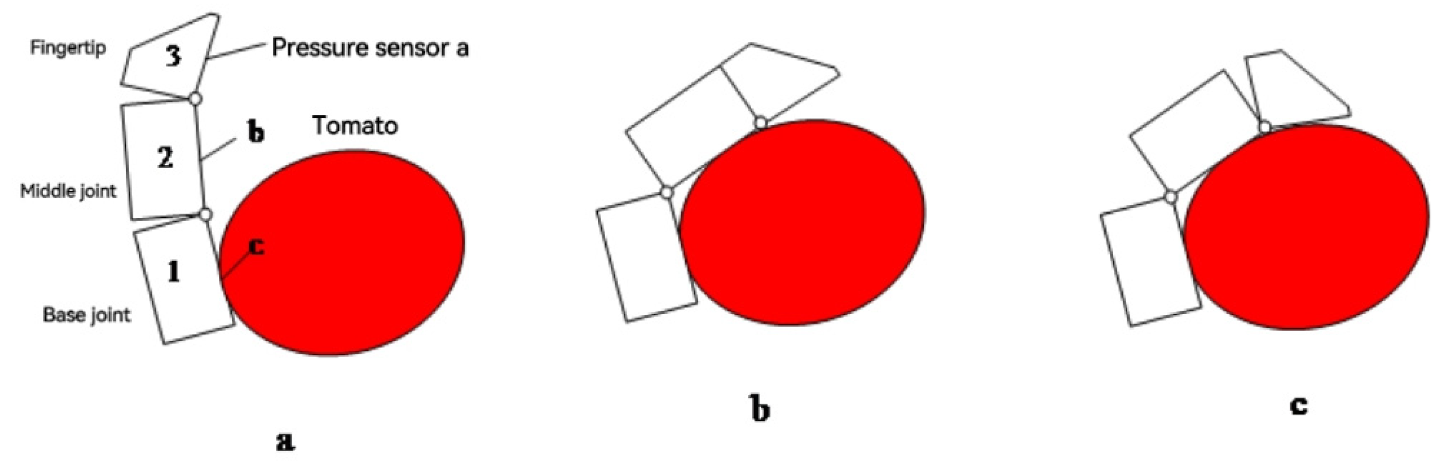
2.1. Mechanistic Analysis of the Motion Characteristics of Tomato Picking End-Effectors

In tomato picking, a hybrid force/position control strategy was proposed to reduce damage [17]. Its control flow is shown in Figure 1. The picking process of tomatoes by the end-effector using hybrid force/position control was divided into two stages. In the first stage, the end-effector was position-controlled according to the fitted model of the tomato shape, and the joints were driven to a predetermined position via a stepper motor; in the second stage, force control was applied after the joints of the end-effector touched the tomatoes, and the stepper motor was controlled to rotate and increase the force between the end-effector and the tomatoes to achieve the desired effect of reliably grasping tomatoes without causing damage to them. When position control was applied to the end-effector, force control failed, the stepper motor was driven to θ i (the rotation angle of each joint) and at which point the end-effector was very close to the tomato. Then, if the pressure value was greater than zero, the end-effector touched the tomato, and at which point the position control ended and the force control started. Combining the maximum pressure that the tomato could withstand and the force detected by the sensor in real time, the end-effector was able to grasp the tomato smoothly via the contact force feedback control algorithm [18].
In the first stage of tomato picking, an ellipsoidal curve was used to fit the tomato’s three-dimensional contour. The standard ellipsoidal curve is shown in Equation (1), and the corresponding three-dimensional contour and the corresponding positions of a, b and c in the ellipsoid curve in the tomato are shown in Figure 2, where a and b indicate the length and width of the minimal circumscribed rectangle of the tomato profile from the top-view, and c indicates the height of the tomato from the front- or side-view.
x 2 a 2 + y 2 b 2 + z 2 c 2 = 1 ,
The body-centered coordinates of the tomato (x, y, z) and the parameters a, b and c were obtained from the vision sensor. The spatial coordinates of the fingertip were obtained by converting the center of the palm coordinate system to the center point of the tomato, which was used as the origin of the coordinate system. Finally, the rotation angles of each joint θ 1 , θ 2 , θ 3 were obtained by the kinematic inverse solution to realize the position control of the end-effector.
In the second stage of tomato picking, where each joint was very close to the tomato surface, the force control stage was entered. Here, a contact force feedback control algorithm was proposed, and the force control block diagram is shown in Figure 3.
Because the three-finger end effector can achieve the purpose of better envelopment with less materials [19], the tomato picking end effector has three fingers with the same structure, and the contact force analysis of one finger is taken as an example to analyze the force of the end effector when grabbing tomatoes, as shown in Figure 4.
We take F i 1 , F i 2 and F i 3 to denote the contact force between the base joint, middle joint and fingertip of the ith finger, respectively, and F 1 , F 2   and F 3 to denote the contact force of the three fingers when picking the tomato.
F 1 = F 11 F 12 F 13 F 2 = F 21 F 22 F 23 F 3 = F 31 F 32 F 33
Then, the contact force between the picking end-effector and the tomato is given, and the contact force is given by
F = F 11 F 12 F 13 F 21 F 22 F 23 F 31 F 32 F 33
According to references [20,21] stating that the average force of 10 N crushes tomatoes, when the peak force increases by 1 N, the mechanical damage degree of tomatoes increases by 2.8% on average. Therefore, to reduce the damage of the tomatoes as much as possible, the maximum pressure that a tomato can withstand was set as F q = 3 N and this force was used as the limiting value. By collecting the value of the pressure sensor in real time, the contact force between each joint and the tomato was detected, and the controller controlled the stepper motor forward or backward accordingly. When Δ F < 0 , the stepper motor was controlled to rotate forward to bring each joint close to the tomato. When Δ F 0 . 2 F q , the speed of the stepper motor was reduced, and when 0 < Δ F < 0.1   F q , the rotation of the stepper motor was stopped. In this process, to prevent F i j from being too large and causing damage to the tomato, when Δ F > 0.1 F q , the stepper motor was driven to reverse the rotation.
Since the end-effector contained three fingers with the same structure, only the grasping process of a single finger was analyzed; the other two fingers conducted a similar grasping process, which is shown in Figure 5. Figure 5a, Figure 5b and Figure 5c are schematic diagrams respectively showing that the base joint contacts the tomato, the base joint and the middle joint contact the tomato at the same time, and the three joints contact the tomato at the same time. In the bounding and grasping process, the base joint stepper motor was first turned, and base joint 1 started to approach the targeted tomato. When the feedback value of the pressure sensor c was greater than zero, indicating that base joint 1 had touched the tomato, the base joint stepper motor stopped rotating; then, the middle joint stepper motor was turned to drive the middle joint 2 to touch the tomato, and when the feedback value of pressure sensor b was greater than zero, the middle joint 2 stepper motor stopped rotating; finally, the fingertip stepper motor was turned to drive Fingertip 3 to touch the tomato, and when the feedback value of the pressure sensor was greater than zero, the fingertip stepper motor stopped rotating, and the process of the end-effector bounding and picking the tomato ended. To enable the end-effector to steadily grasp the tomato, after each joint was in contact with the tomato, the stepper motor continued to rotate, and pressure sensors a, b and c provided real-time feedback on the contact force F i j between each joint and the tomato being picked. When Δ F 0 . 2 F q , the speed of the stepper motor was reduced, and when 0 < Δ F < 0.1 F q , the rotation of the stepper motor stopped, and the tomato picking process was completed.
Here, the tomato picking end-effector was designed with a mechanical structure and control system based on the above hybrid force/position control strategy, and the corresponding component strength verification, motor performance verification and kinematic simulation verification were conducted.

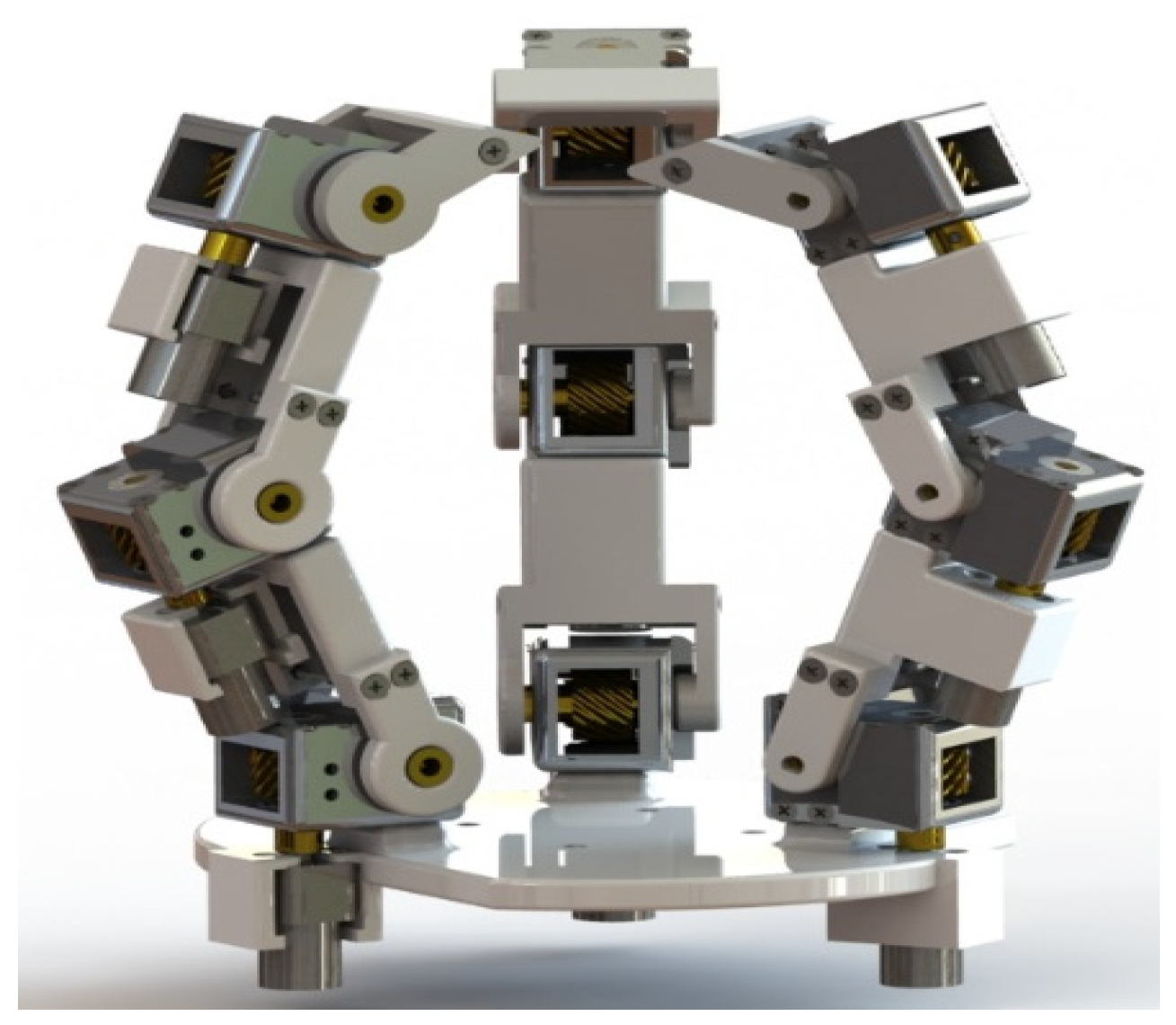
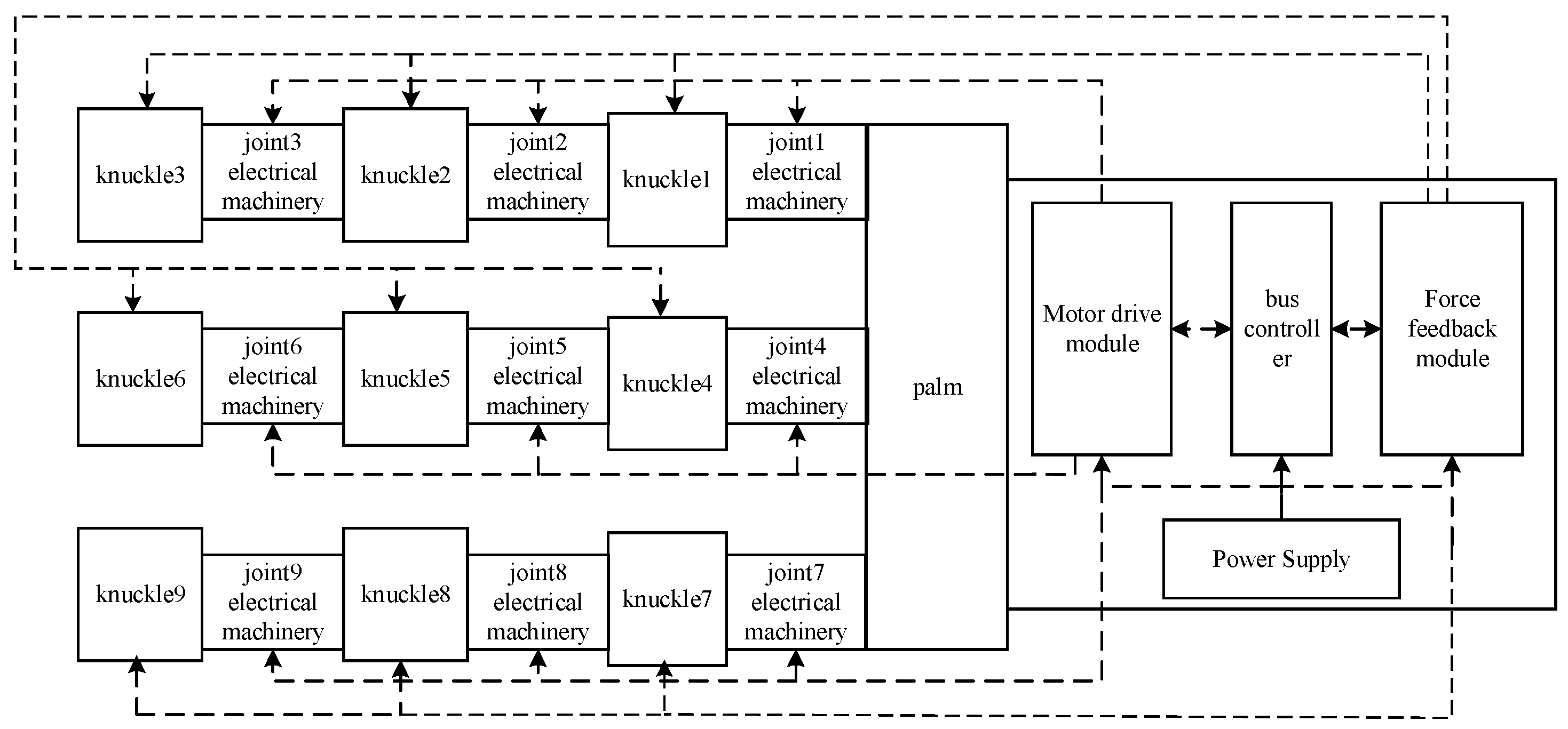
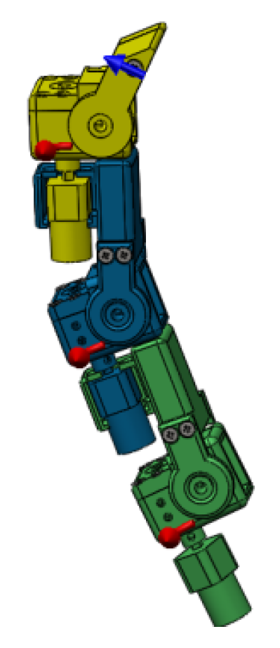
2.2. Tomato Picking End-Effector Mechanical Structure Design and Calibration

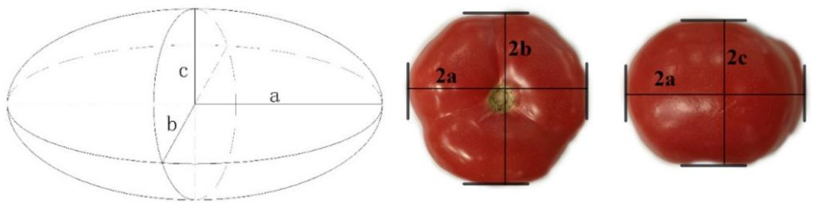
2.2.1. Determining the Size of the Tomato Picking End-Effector

The mechanical design of the tomato picking end-effector mimics the structure of the human hand. The human hand contains 19 bones: 5 of which are metacarpals and 14 of which are phalanges. The average length of each phalange of the middle finger in adult males is given as follows: distal phalanges: 26.4 ± 2.0 mm, middle phalanges: 25.6 ± 2.3 mm and proximal phalanges: 50.5 ± 4.7 mm [22]. The diameter of ripe tomatoes is generally 50 mm to 80 mm [23]. Thus, the length of the tomato picking end-effector phalanges was initially selected to be 60 mm, 60 mm and 40 mm, which is 1.56 times the approximate human hand. In the tomato picking process, the end-effector was required to bind the fruit, and three fingers were positioned and evenly distributed in a circle. The fingertips, middle finger joints, base finger joints, commutator and motor of the manipulator were modeled in 3D using SolidWorks. After modeling all other parts of the manipulator, the 3D model was assembled, as shown in Figure 6. The tomato picking end-effector was a 9-degree-of-freedom fully driven end-effector with high flexibility and complex control, and its structure is shown in Figure 7.

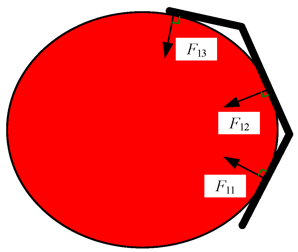
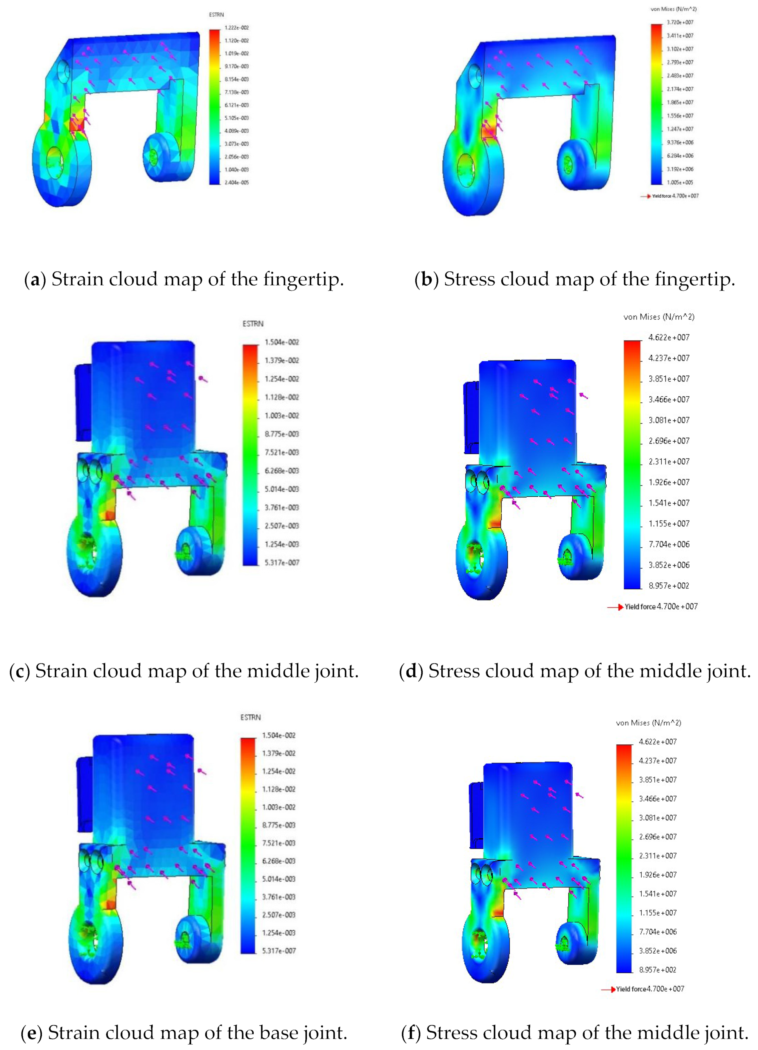
2.2.2. Strength Checking of the Key Parts

In the process of checking the strength of the key components, it was assumed that the tomato variety was JP513, and the weight of a single fruit was 130–250 g. The force acting on the three joints of the fruit changed with a change in finger pose. In the extreme pose, a single joint fully bore the weight of the fruit, and the load was the product of the maximum weight of the fruit and the safety factor. Considering the safety factor of 1.2, the load was given as P = m g f = 0.25 9.8 1.2 = 2.94 N . The Future 8000 resin was chosen as the end-effector material, and its elastic modulus is 2.37–2.65 GPa, Poisson’s ratio is 0.41 and mass density is 1.2 g/cm3. Finite element analysis was performed on the fingertip, middle joint and base joint. The results are shown in Figure 8.
From the results of the finite element analysis, it can be seen that the stress condition of each joint in the extreme pose was as follows: the maximum strain of the fingertip was 1.22 × 10⁻² mm, and the maximum stress was 37.2 MPa; the maximum strain of the middle joint was 1.504 × 10⁻² mm, and the maximum stress was 46.2 MPa; the maximum strain of the base joint was 1.504 × 10⁻² mm, and the maximum stress was 46.2. The yield strength of the Future 8000 resin was 47 MPa. These results show that the maximum stress was reached only locally, and the maximum stress in all three joints was less than the yield strength of the resin. Therefore, the Future 8000 resin could meet the strength requirements of the parts in tomato picking operations.

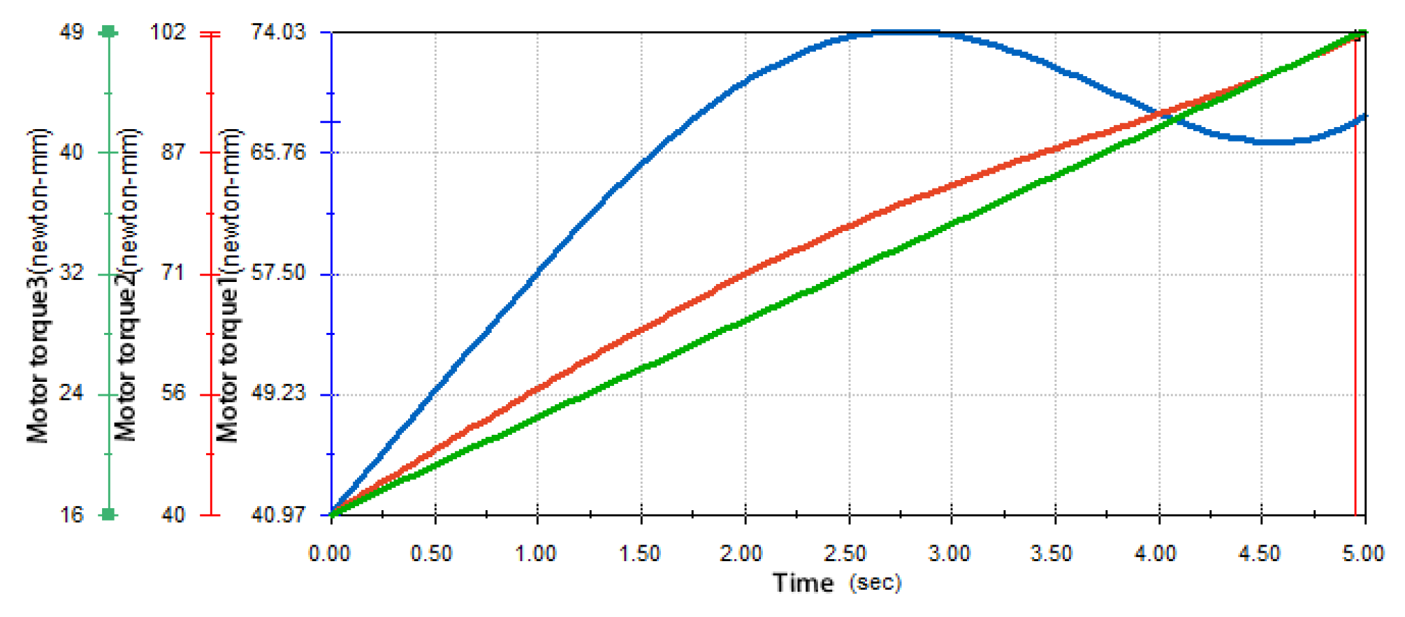
2.2.3. Motor Performance Checking

The CHS-GM12-10BY stepper motor was chosen as the finger joint motor. To verify that the motor could meet the requirements of picking operations in the extreme pose, the motor torque was checked using the Motion component of SolidWorks. By setting motor motion parameters in the assembly and then adding load cases, the output curve of the motor torque was generated automatically. To simplify the operation, it was assumed that the time for the end-effector to complete a grasp was 5 s. Equal-speed motors were added in each of the three joints, and the relative rotation angles of the three motors were 60°, 30° and 30°. At the distal finger end, the fruit gravity of 3 N was set to always be perpendicular to the fingertip (assuming that it was always in the extreme pose), as shown in Figure 9.
The simulation results of the torque of the three joint motors of each finger of the end-effector in the motion environment are shown in Figure 10. From the curve, it can be seen that the maximum output torque of the motor was 102 N.mm, which was much smaller than the holding torque of the motor, 250 N.mm. Therefore, the CHS-GM12-10BY-type stepper motor met the performance requirements of the tomato picking end-effector for picking operations in extreme poses.

2.3. Kinematic Simulation Analysis of Tomato Picking End-Effector

This section first models the joint motion of the end-effector using kinematic analysis to describe the motion of the end-effector mathematically. It then uses kinematic simulation tests to verify the accuracy of the joint motion model construction.

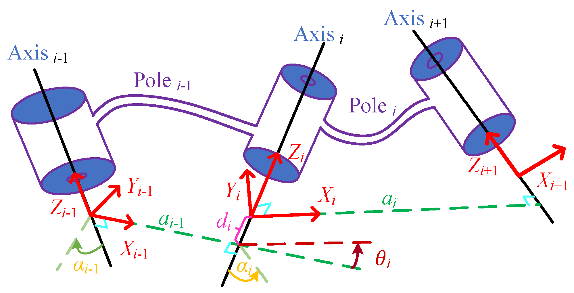
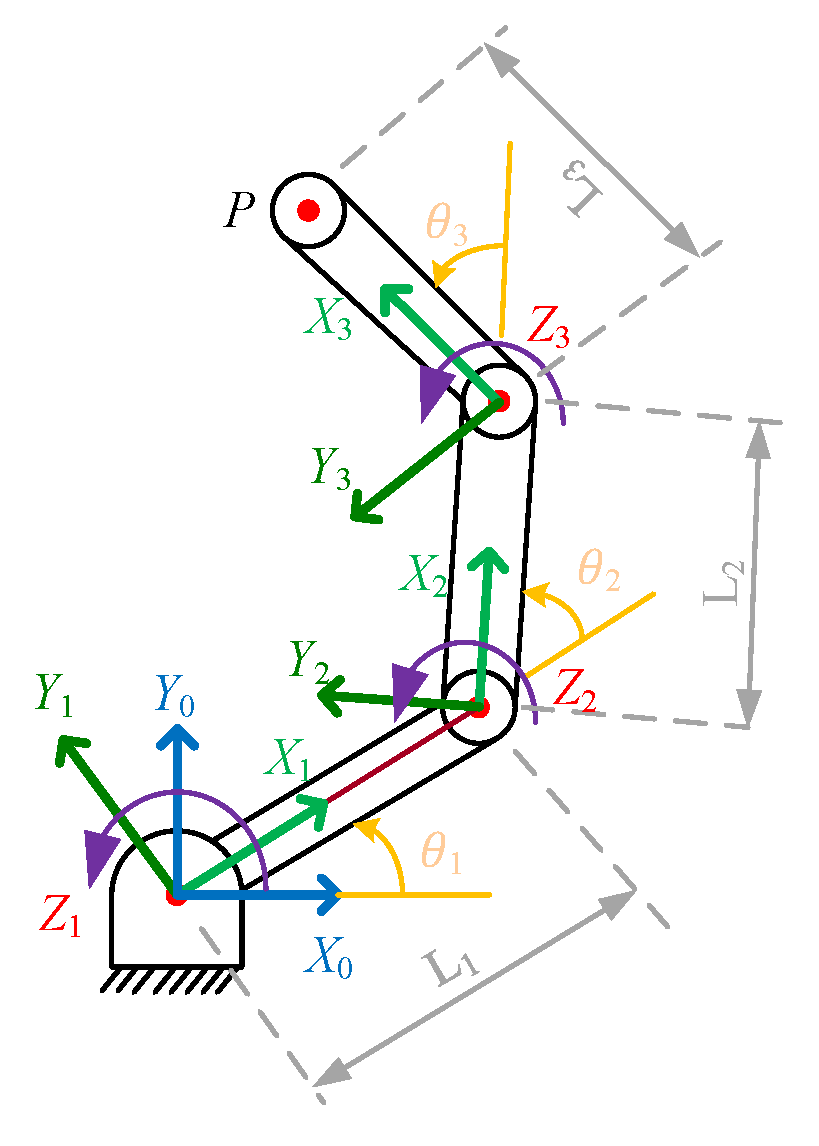
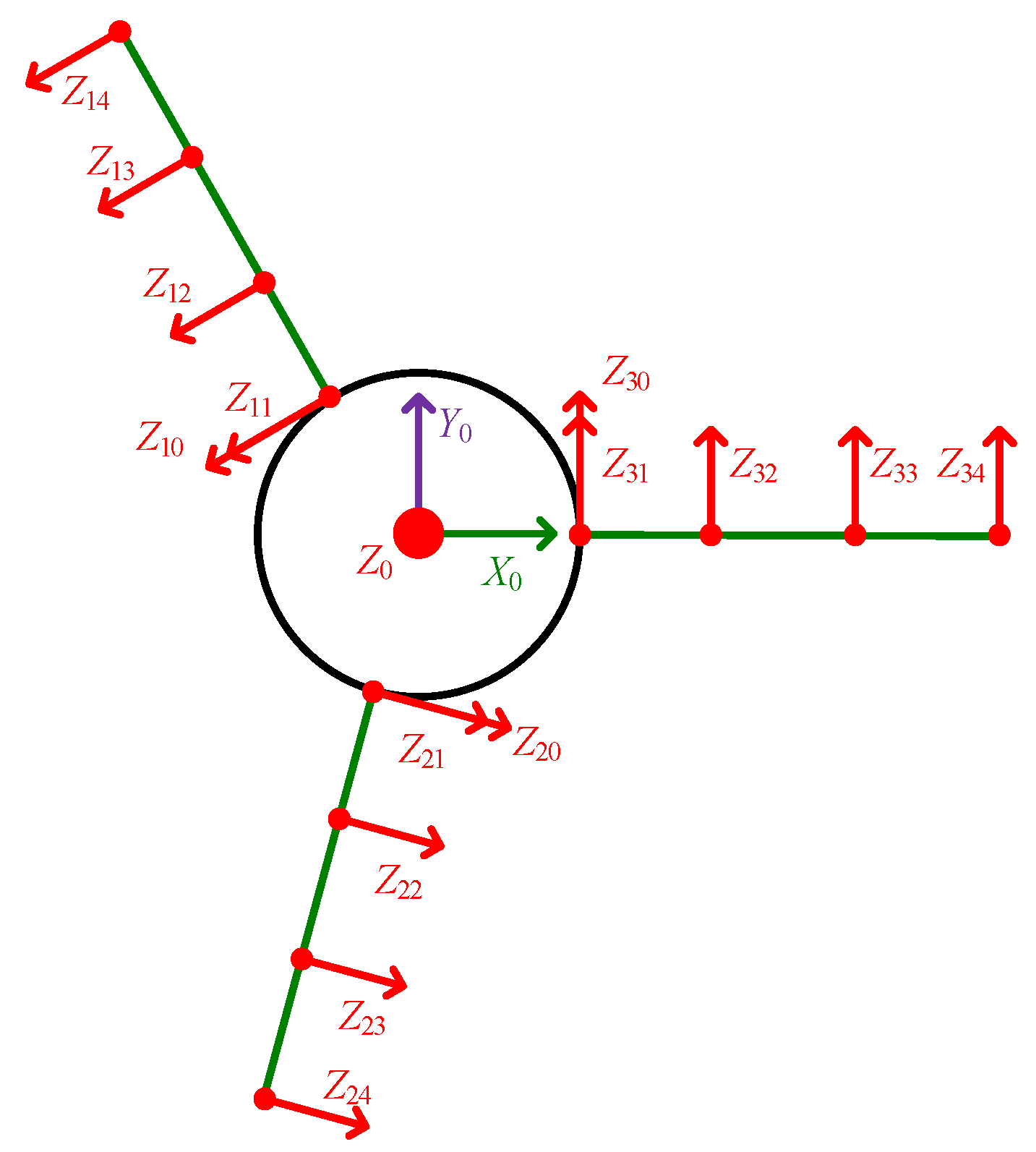
2.3.1. Kinematic Analysis

Here, the Craig method [24] was used to analyze the rationality of the entire picking operation process of the tomato picking end-effector from the kinematic perspective. First, the D-H coordinate system [25,26] of the end-effector rotating joint link and the single-finger model were established, as shown in Figure 11 and Figure 12. There were three rotational subsets of the end-effector, and for each rotational subset, the parameters α i , a i and d i were known while the parameter θ i was unknown. When controlling the end-effector, θ i was changed by the rotation of the motor shaft to accomplish a specific grasping and releasing action.
In the simplified single-finger structure of the end-effector, the Z i   axes in each local coordinate system were always parallel, and so the value of the parameter α i 1 was always zero. The value of a i 1 was the link length L i ; since the axes X i 1 and X i in the two adjacent coordinate systems always moved in the same plane and intersected at the joint center, θ i was the angle between the two adjacent links, and d i was always zero. To prevent interference during the rotation, the range of θ i was restricted to (0°~90°).

2.3.2. Forward Kinematic Analysis

With the tomato contour determined, the end-effector was required to execute the correct picking position for each finger joint to complete a precise tomato picking motion. The relationship between the rotation angle of each joint and the fingertip posture was obtained through forward kinematics such that the picking end-effector completed the picking motion by controlling the rotation angle of each joint.
To analyze the spatial coordinates of the end-effector, it was necessary to convert the established local coordinate system to the reference coordinate system. The transformation of the coordinate system is represented as translation and rotation. To convert from the i 1 s t coordinate system to the i th coordinate system, the following operations were performed:
  • Rotation of α i 1 angles around the X i   axis;
  • Translation along the X i   axis by a i 1   lengths;
  • Rotation of θ i   angles around the Z i   axis;
  • Translation along the Z i axis by d i   lengths.
The general equation of the chi-square transformation matrix from the i 1 s t coordinate system to the ith coordinate system is
T i i 1 = 1 0 0 0 0 c o s α i 1 s i n α i 1 0 0 s i n α i 1 c o s α i 1 0 0 0 0 1 1 0 0 0 0 1 0 0 0 0 1 0 a i 1 0 0 1 c o s θ i s i n θ i 0 0 s i n θ i c o s θ i 0 0 0 0 1 0 0 0 0 1 1 0 0 0 0 1 0 0 0 0 1 0 0 0 0 1 = c o s θ i c o s α i 1 s i n θ i s i n α i 1 s i n θ i 0 s i n θ i c o s α i 1 c o s θ i s i n α i 1 c o s θ i 0 0 c o s α i 1 c o s α i 1 0 a i 1 0 0 1
The transformation matrix of the 3rd coordinate system to the 1st coordinate system is T 3 0 = T 1 0 T 2 1 T 3 2 , taking α i 1 = 0 and α i = L i   into the above equation, and ordering s i = s i n θ i , c i = c o s θ i , s i j k = s i n θ i + θ j + θ k and c i j k = c o s θ i + θ j + θ k , hence
T 3 0 = c 123 s 123 0 0   s 123 c 123 0 0   0 0 1 0   L 1 c 1 + L 2 c 12 L 1 s 1 + L 2 s 12 0 1  
the pose matrix of the fingertip endpoint P in the base coordinates is
P 0 = T 3 0 P 3 = c 123 s 123 0 0   s 123 c 123 0 0   0 0 1 0   L 1 c 1 + L 2 c 12 + L 3 c 123 L 1 s 1 + L 2 s 12 + L 3 s 123 0 1 = n x n y n z 0   o x o y o z 0   a x a y a z 0   P x p y P z 0
The pose matrix: n x n y n z o x o y o z a x a y a z = c 123 s 123 0 s 123 c 123 0 0 0 1 .
The translation matrix: P x P y P z = 60 c 1 + 60 c 12 + 40 c 123 60 s 1 + 60 s 12 + 4 0 s 123 0 .
Equation (5) shows that the coordinates (x, y, z) of the fingertip in the base coordinate system can be uniquely determined if the angles of the three joints θ 1 θ 3   are given. This signifies that the end-effector motion can be accurately controlled given the angles of the joints. However, the accuracy of the tomato picking end-effector motion still needs to be verified from an inverse kinematic point of view.

2.3.3. Inverse Kinematic Analysis

In the tomato picking process, the rotation angle of each joint in a certain pose can be solved via inverse kinematics so that the joint motor is controlled to rotate to the corresponding angle to complete fruit picking. The commonly used methods for inverse kinematic analysis are algebraic and geometric methods [27], and in this paper, the algebraic method was used to solve the problem.
From T 1 0 P 0 = T 3 1 P 3 = T 2 1 T 3 2 P 3 , it can be obtained that
T 1 0 P 0 = n x c 1 n y s 1 n y c 1 n x s 1 n x 0 o x c 1 + o y s 1 o y c 1 o x s 1 o z 0 a x c 1 + a y s 1 a y c 1 + a x s 1 a z 0 P x c 1 + P y s 1 P y c 1 P x s 1 P z 1 = c 123 s 123 0 0 s 123 c 123 0 0 0 0 1 0 60 c 1 + 60 c 12 + 40 c 123 60 s 1 + 60 s 12 + 40 s 123 0 1
According to Equation (6), it can be obtained that
60 c 1 + 60 c 12 = p x 40 n x 60 s 1 + 60 s 12 = p y 40 n y
Combining Equations (6) and (7), it can be obtained that
θ 1 = a r c t a n ( P y 40 n y P x 40 n x ) a r c t a n ( 60 s i n θ 2 60 + 60 c o s θ 2 ) θ 2 = a r c c o s ( ( P x 40 n x ) 2 + ( P y 40 n y ) 2 60 2 2 2 60 2 ) θ 3 = a r c t a n ( n y n x ) θ 1 θ 2
From Equation (8), it can be seen that given an end-effector pose, the rotation angle of each joint θ i (i = 1, 2, 3) can be solved using the inverse kinematic method, which realizes accurate control of the end-effector and thus achieves the smooth picking of fruit.

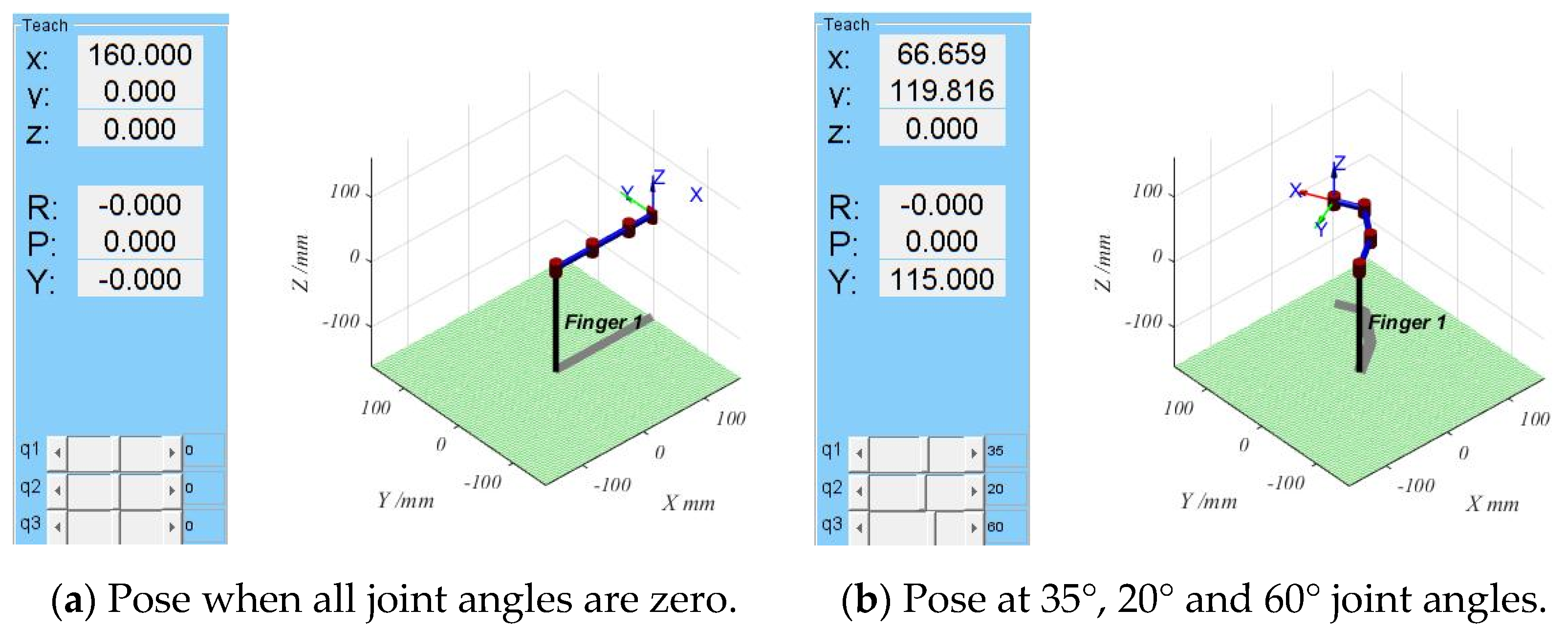
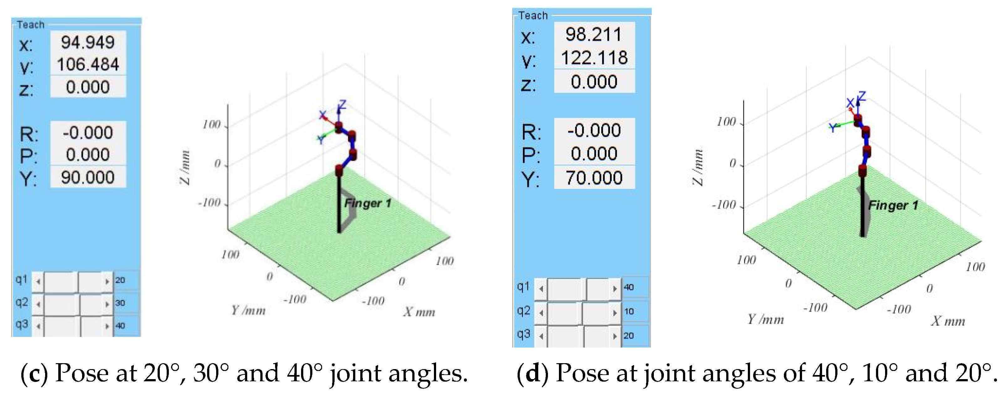
2.3.4. Kinematic Simulation Verification

In this paper, the accuracy of the forward kinematics was verified using the following procedure: First, a single-finger test model of the tomato picking end-effector was established using the MATLAB Robotics Toolbox plug-in. The requirements for modeling were as follows: the lengths of the connecting links a 1 , a 2 and a 3 were 60 mm, 60 mm and 40 mm, respectively, and the range of the joint rotation angles θ 1 , θ 2 , θ 3 was 0°–90°. Then, four different groups of joint angles were selected, and the coordinates of the fingertip spatial position corresponding to each group were calculated according to Equation (5). The results are shown in Table 1. The four sets of values from Table 1 were input to the established single-finger test model, and the simulation results of MATLAB were obtained, as shown in Figure 13.
From the results in Figure 13 and Table 1, it can be seen that the simulation results agree with the calculation results, which shows that the forward kinematic expression solved in this paper is correct and can execute the forward motion of the end-effector.
To verify the accuracy of the inverse kinematics, first, the joint angle was given, and the corresponding fingertip coordinate values were calculated according to the forward kinematics. Then, the inverse kinematics were solved according to the obtained fingertip coordinates to obtain the corresponding joint rotation angle. Finally, whether the kinematic inverse analytic formula is correct was verified by comparing the obtained joint angles with the given joint angles, and the specific data are shown in Table 2.
As seen from the data in the table, the data for the forward and inverse kinematics solutions are identical up to four decimal places, indicating that the forward and inverse kinematics are correct within a certain range of motion. Therefore, the feasibility of the tomato picking end-effector was verified from both the forward and inverse kinematic perspectives.

2.4. Tomato Picking End-Effector Trajectory Planning and Workspace Simulation Verification

To reduce the damage caused by automated picking and to improve picking efficiency, this section first addresses the trajectory planning of the end-effector picking action to reduce the impact force on the tomato, and then demonstrates that the operating range of the end-effector can meet the tomato picking requirements based on workspace simulation.

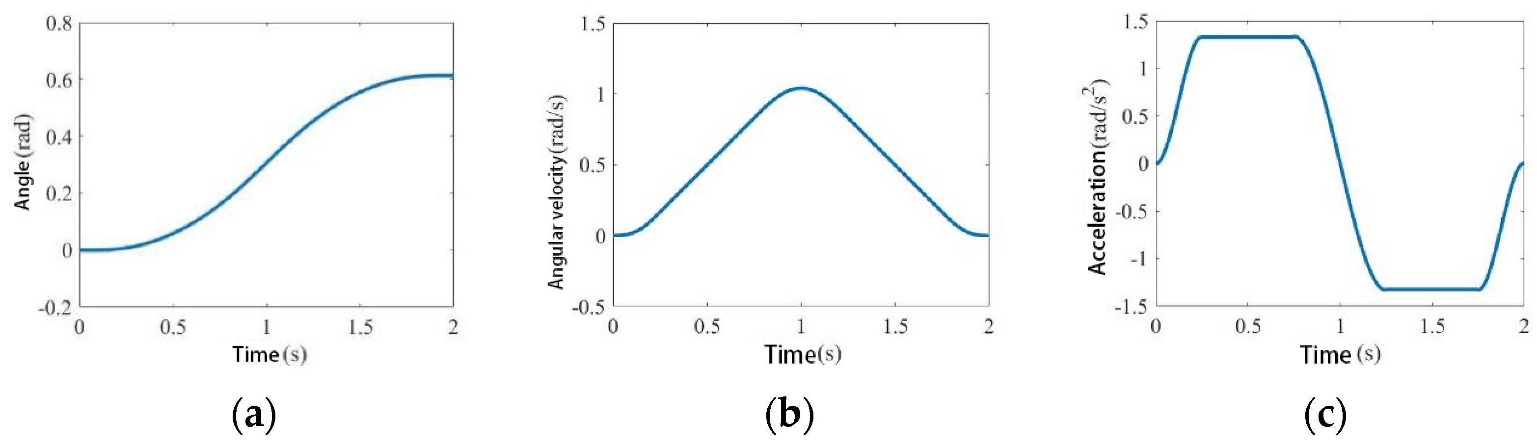
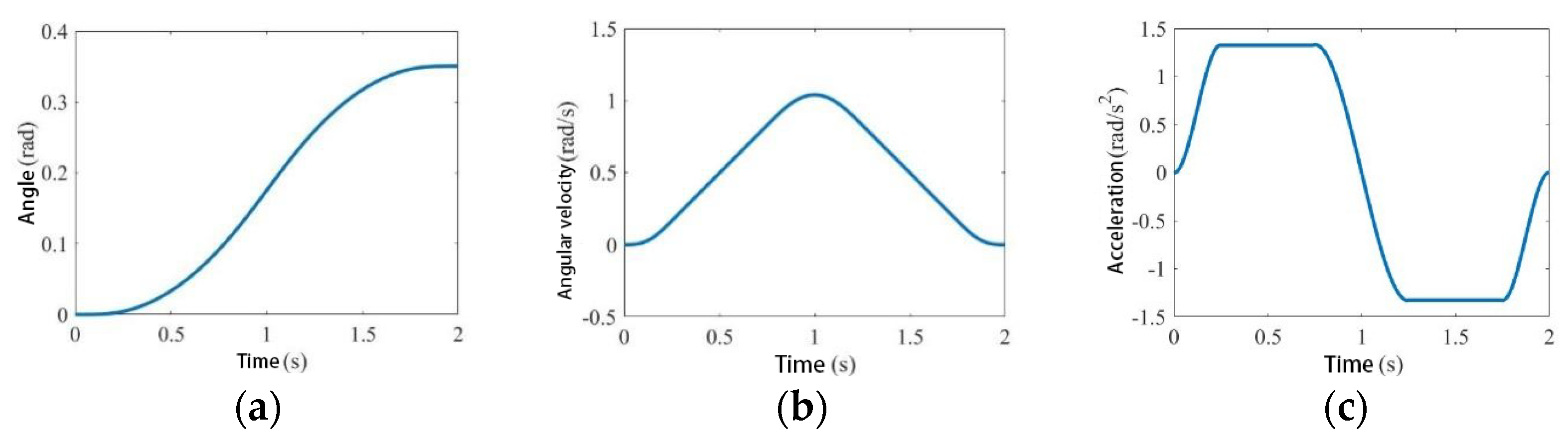
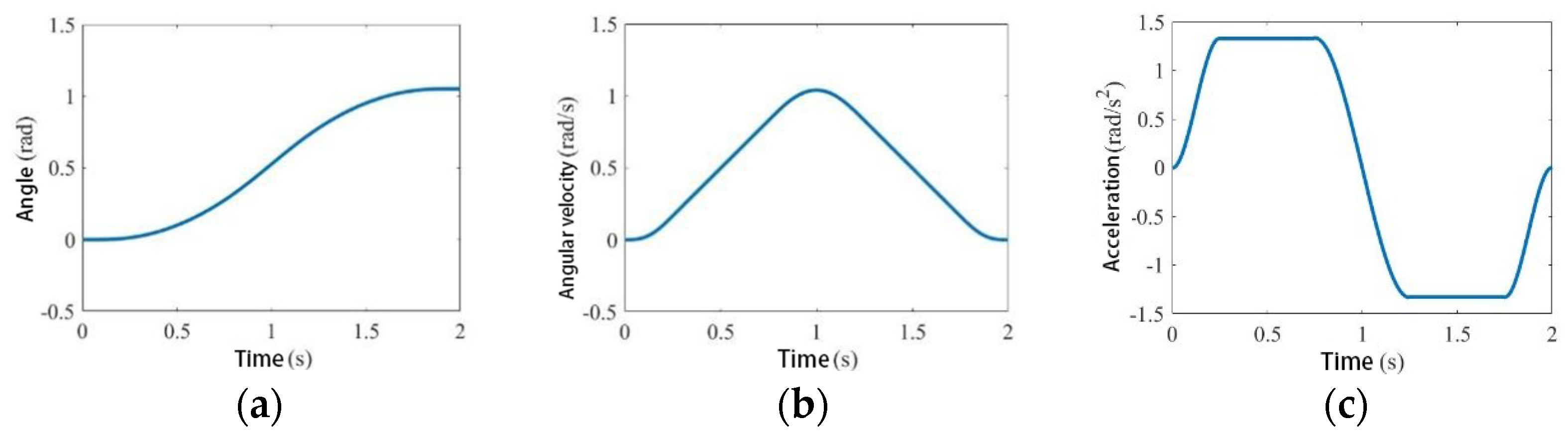
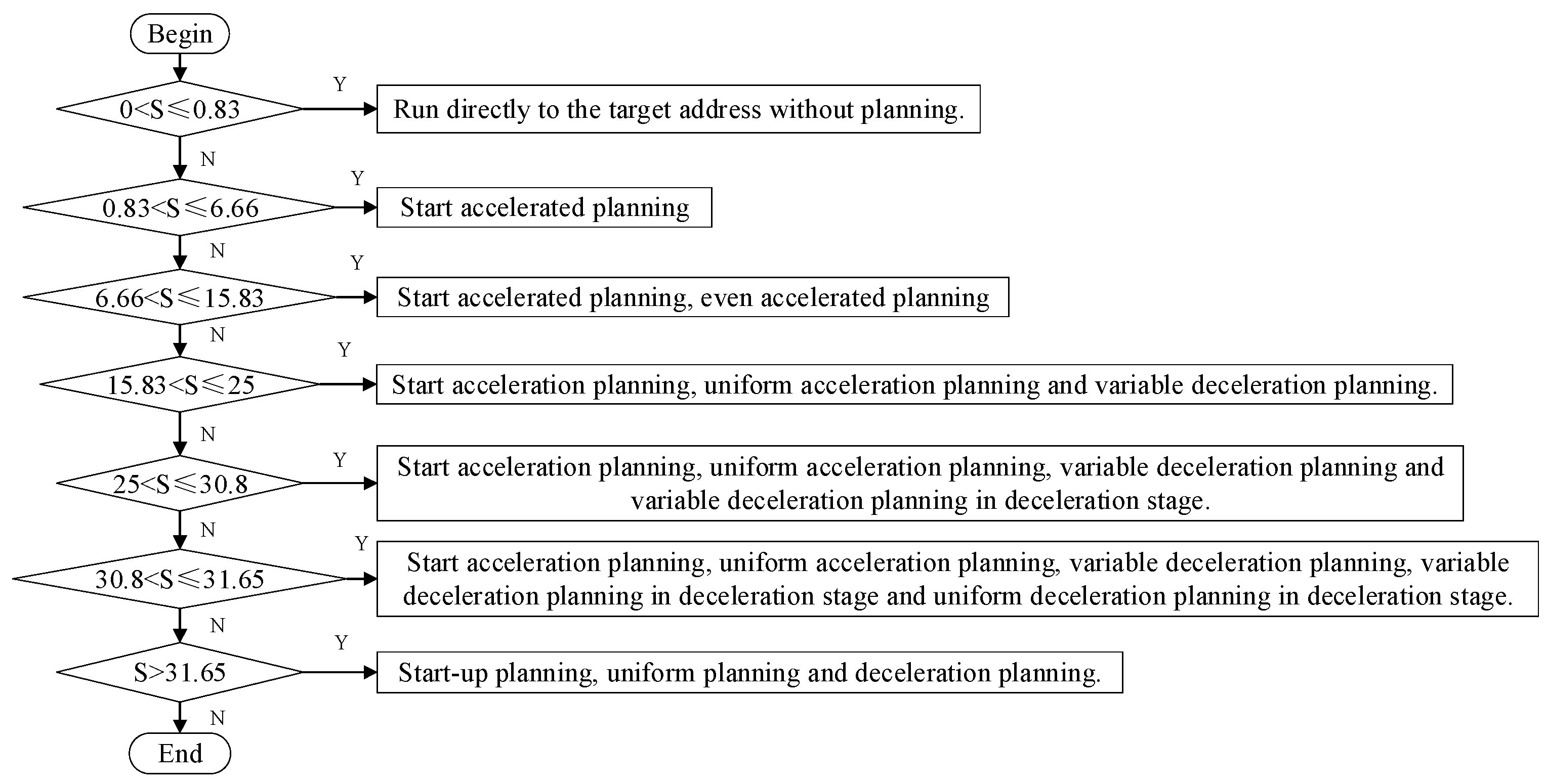
2.4.1. Trajectory Planning

Based on the theoretical analysis of position control in Section 2, it is clear that the position control has end-effector joint angle control. However, if the joints are driven directly to the target position, the speed is too fast, and a large impact force is generated at the moment of contact between the end-effector and the tomato. This impact may not only damage the tomato but also the end-effector components. Therefore, the impact force needs to be reduced via trajectory planning. The modified trapezoidal law of motion offers the advantages of continuous acceleration, leap curves and short trajectory times, but also the disadvantage of sudden changes such as a jerk at the beginning and end of motion, which causes flexible shocks to the system [28]. To address this problem, the modified sinusoidal acceleration curve motion law for trajectory planning was adopted, which could eliminate the problem of sudden position and force changes at the beginning and end of the motion and make the end-effector move smoothly.
From Section 2.2.1, the tomato picking end-effector designed in this paper is symmetric, so its single-finger model was applied for trajectory planning, and the sinusoidal modified trapezoidal acceleration curve mentioned in the literature [29] was derived to obtain the jerk curve.
Figure 14a, Figure 14b and Figure 14c respectively show the curves of angle, angular velocity and angular acceleration of joint 1 with time. The three graphs in Figure 15 and Figure 16 are curves of the relevant parameters of joint 2 and joint 3 corresponding to Figure 14 changing with time, respectively. From the (b) and (c) diagrams of Figure 14, Figure 15 and Figure 16, it can be seen that at the beginning and end of the joint movement, the joint velocity and acceleration were both zero, and there was no abrupt change in the slope of the curve, indicating that there was no obvious movement impact during the starting and braking of the joint movement of the end effector, and there was no abrupt change in the slope of the whole curve in the angle, angular velocity and angular acceleration images of Figure 15, Figure 16 and Figure 17.

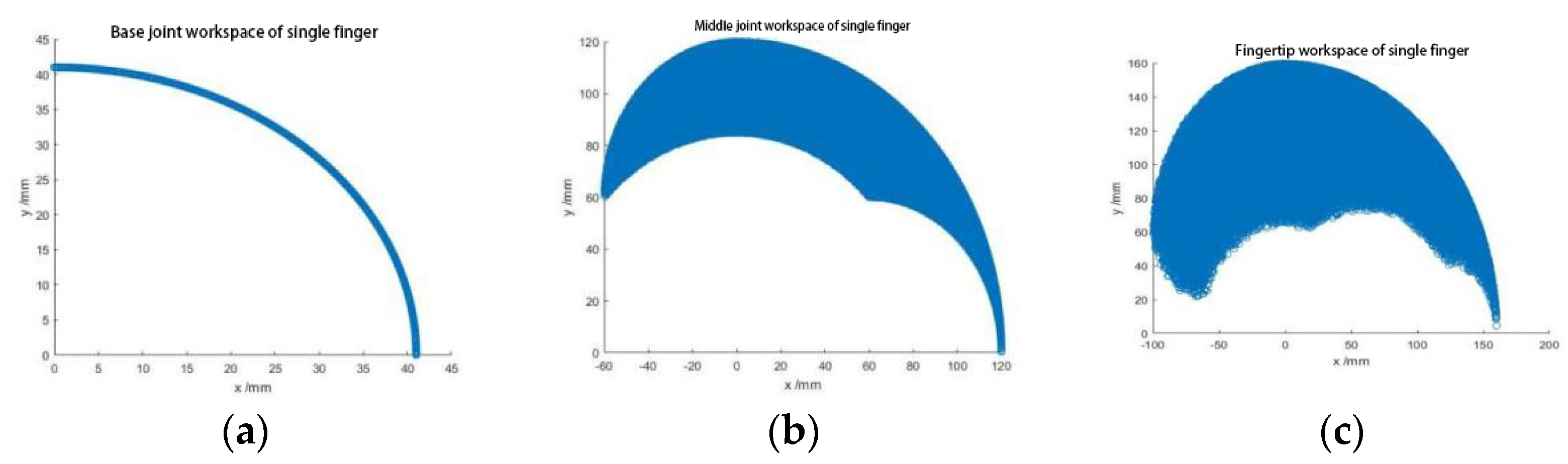
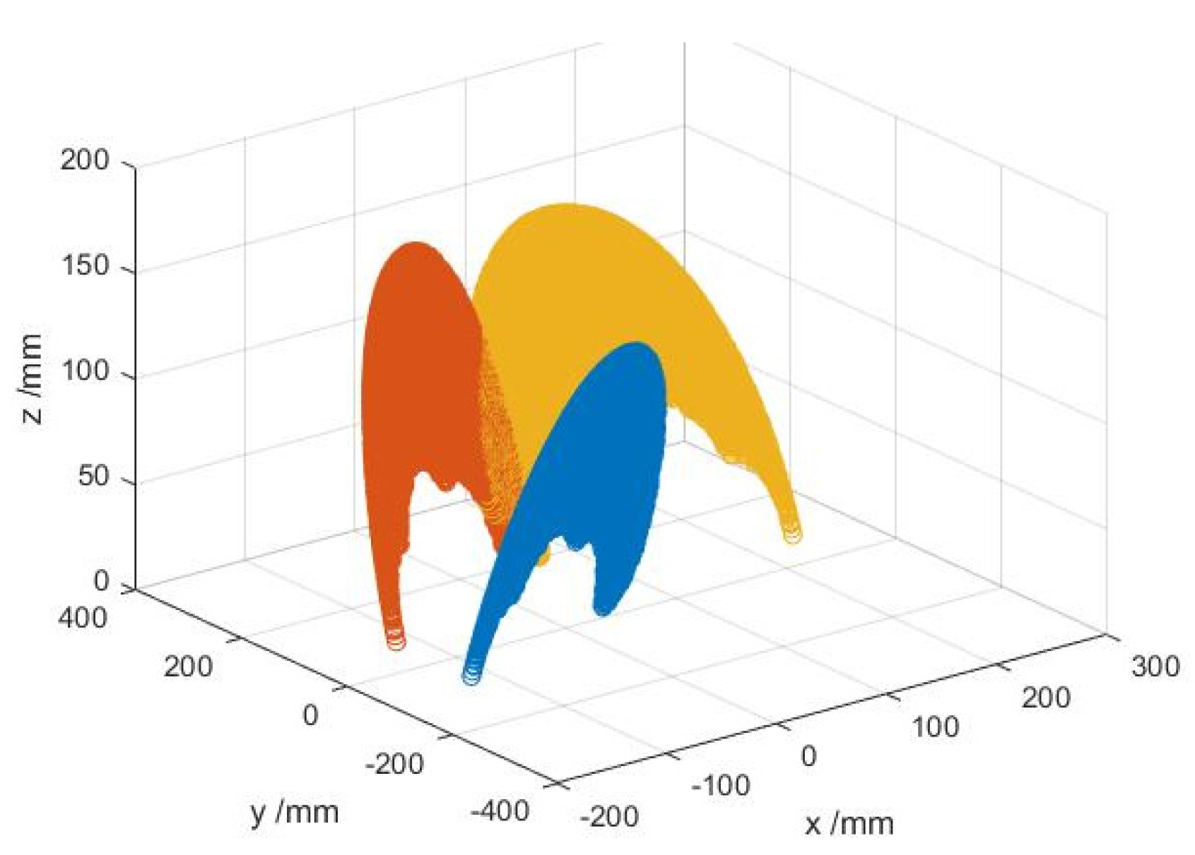
2.4.2. Workspace Simulation Verification

Based on the end-effector structure designed in Section 3.1, a workspace simulation was performed using MATLAB. First, multiple end-effector joint motion space points were randomly generated. Then, based on the D-H coordinate system established in Section 2.3.1 for the end-effector rotating joint link and the end-effector single-finger model, the coordinates and transformation matrix of the generated random points were obtained, and then the spatial point coordinates of the joint motions were solved. Finally, the workspace image of the end-effector was drawn using the plot function in MATLAB.
The kinematic forward solution model yielded the expressions for the base joint P x , P y , middle joint P x , P y and fingertip P x , P y of the finger as a function of the base coordinates of the finger, respectively, as follows:
P x = 60 c 1 , P y = 60 s 1 , P x = 60 c 1 + 60 c 12 , P y = 60 s 1 + 60 s 12 , P x = 60 c 1 + 60 c 12 + 40 c 123 , P y = 60 s 1 + 60 s 12 + 4 0 s 123 ,
The rotation angle of each joint of the picking end-effector is between 0° and 90°. In MATLAB, 100,000 random points were generated, and their coordinates were brought into Equation (9) to obtain the points within its working space and to find the workspace of the base finger, middle finger and fingertip of the end-effector, as shown in Figure 17.
Based on the tomato picking end-effector structure, an entire D-H coordinate system was established for the hand, as shown in Figure 18. The three fingers were symmetrically distributed at 120° to each other on a circular palm with a radius of 40 mm.
This section may be divided by subheadings. It should provide a concise and precise description of the experimental results, their interpretation, as well as the experimental conclusions that can be drawn.
Substituting the parameters of Table 3 into Equation (4), the transformation matrix of the Z 10 coordinate system relative to the Z 0 coordinate system was obtained as follows
T 10 0 = c 10 s 10 0 0 s 10 c o s α 10 c 10 c o s α 10 s i n α 10 0 s 10 s i n α 10 c 01 s i n α 10 c o s α 10 0 a 10 c 10 a 10 s 10 d 10 1 ,
From the transformation matrix, the spatial position coordinates of the fingertip of Finger 1 could be obtained as
P x = c 10 a 1 c 1 + a 2 c 12 + a 3 c 123 + a 10 + a 10 , P y = s 10 a 1 s 1 + a 2 s 12 + a 3 s 123 + a 10 + a 10 , P z = s i n α 10 a 1 s 1 + a 2 s 12 + a 3 s 123 ,
Similarly, the spatial position coordinates of the fingertips of Fingers 2 and 3 could be obtained, and the MATLAB simulation was used to obtain the three-dimensional workspace of the fingertips, as shown in Figure 19.
The simulation results for the workspace show that the end-effector could pick tomatoes in the diameter range of 50 mm to 120 mm. As mentioned in Section 3.1, ripe tomatoes are generally 50 mm to 80 mm in diameter, whereby this range is included in the range of tomato picking diameters in the simulation results. Therefore, the dimensions of the end-effector meet the requirements of the tomato picking operation.

3. Results

This section builds a real test platform based on the existing simulation results and designs the corresponding control system and remote debugging system. Thereafter, the performance of the end-effector designed is verified through field picking tests on tomatoes.

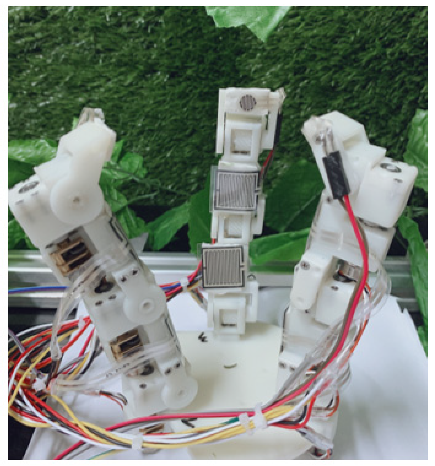
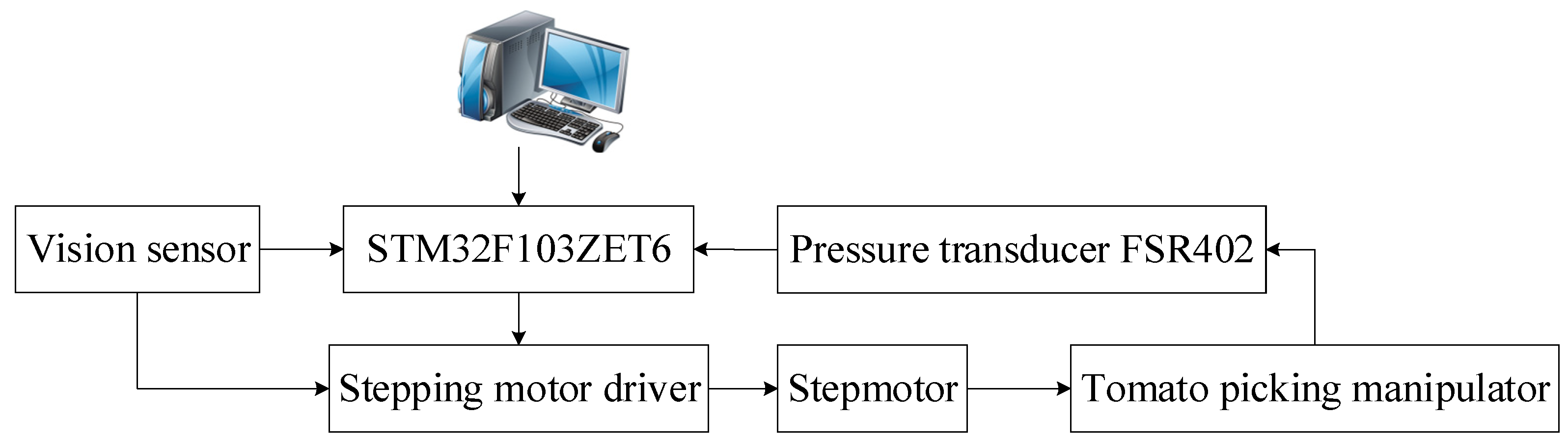
3.1. Test Platform Construction

According to the above simulation results, Future 8000 resin was selected as the material for fabricating the three joint components and the palm, and 3D printing was performed. After machining all of the parts, the tomato picking end-effector was physically assembled, and the overall physical end-effector is shown in Figure 20.
To achieve the separate control of each joint movement of the single finger and coordinated control of the movements of the three fingers of the end-effector (thus ensuring that the end-effector achieves precise picking movements), the tomato picking end-effector control system was designed with an architecture as shown in Figure 21.
The control system included a main control part, power circuit part, motor control part and pressure acquisition circuit part. In the designed tomato picking end-effector, the STM32F103ZET6 microcontroller was selected as the main controller, and the FSR402 thin film pressure sensor was selected to detect the contact force between the end-effector and the tomato in real time. Nine pressure sensors were arranged on each joint, and L9110S was selected as the stepper motor-driven module. In the process of controlling the motion of the end-effector, the stepper motor was controlled in real time based on the collected pressure sensor values with the hybrid force/position control algorithm. Via the motion law described in Equation (8), the speed of the end-effector joint motor was planned, and the start-up phase was divided into the start-up acceleration phase, uniform acceleration phase and variable deceleration phase. According to the motor control requirements, its pulse requirement was 1–2 ms, the configuration timer clock frequency was 1 MHz and the period was 20 ms. Then, the timer duty cycle configuration corresponding to 1–2 ms was 1000–2000, and the motor rotation angle was 180 degrees, such that the control accuracy of the controller was 0.18 degrees. From Equation (8), the motor rotated 0.83 degrees in the start-up acceleration stage, 5 degrees in the uniform acceleration stage and 9.1667 degrees in the variable deceleration stage. Combined with the control accuracy of the motor, the interpolation algorithm was designed. In the acceleration stage, two points were interpolated, 5 t/8 and t(t ≤ 1 s). In the uniform acceleration stage (1 < t ≤ 2), five points were interpolated in equal time. In the variable deceleration phase (1 < t ≤ 2), five points were interpolated simultaneously. With the motor control requirements, the interpolation points meeting the above requirements could be obtained. In the deceleration phase and the start-up phase, the control strategies were reversed. In the uniform acceleration phase, the same isochronous interpolation algorithm was used, and the interpolation points were proportional to the time of uniform motion, with the interpolation performed every 40 ms with pulse increments of two. According to the above control algorithm, the motor operation flow was ultimately designed, as shown in Figure 22.
To realize a simple and convenient end-effector controller, remote wireless debugging software was developed based on Tiny6410. The Linux operating system and Qt software were used to build the development environment. The system read the touch screen control commands from the Tiny6410 through the Linux driver, operated the I/O interface and sent the end-effector pose debugging data through the serial port to the conversion module, which sent the control commands and data to the manipulator controller STM32F103RCT6 through the wireless communication module NRF24L01. In accordance with the end-effector control requirements, the end-effector joint trajectory and the interval time of the control command were operated simultaneously. According to the above requirements, the software flow of the remote wireless debugging module was designed, as shown in Figure 23.

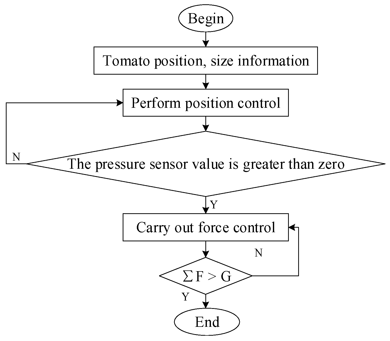
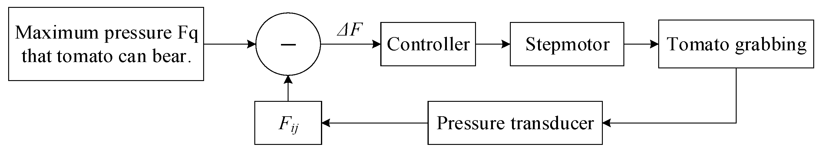
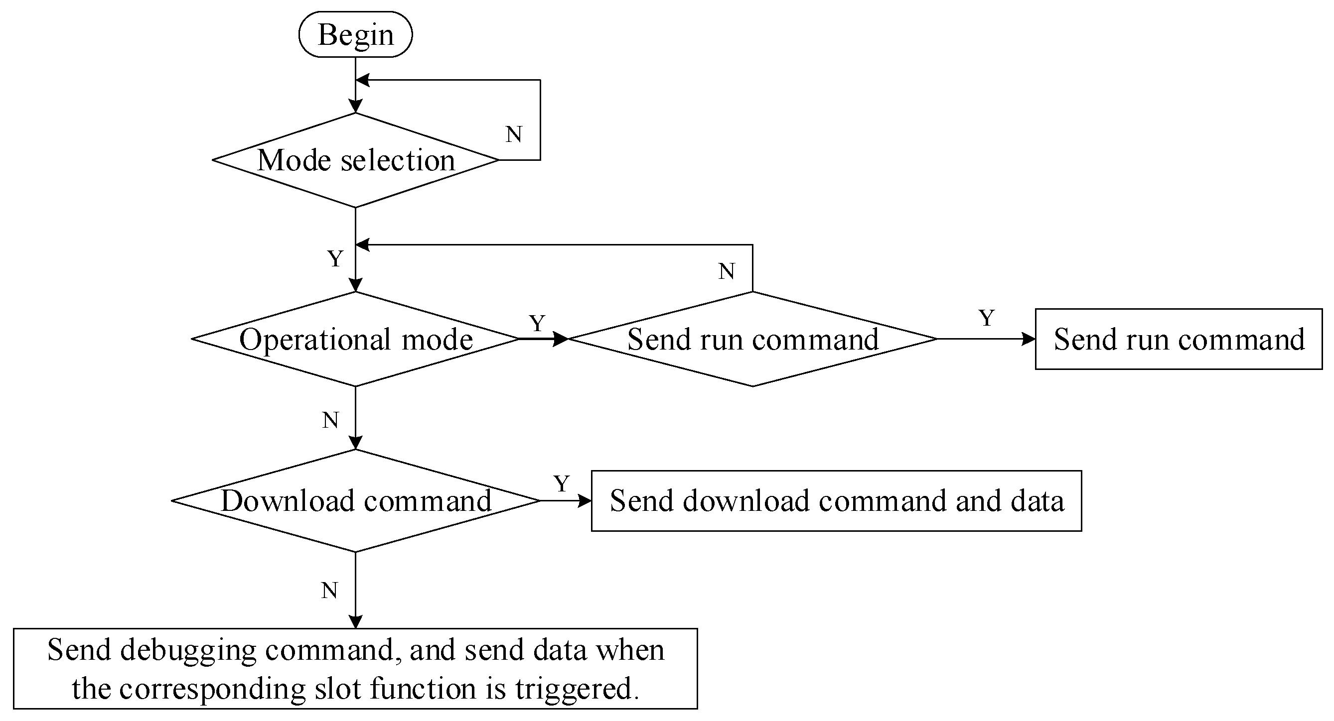
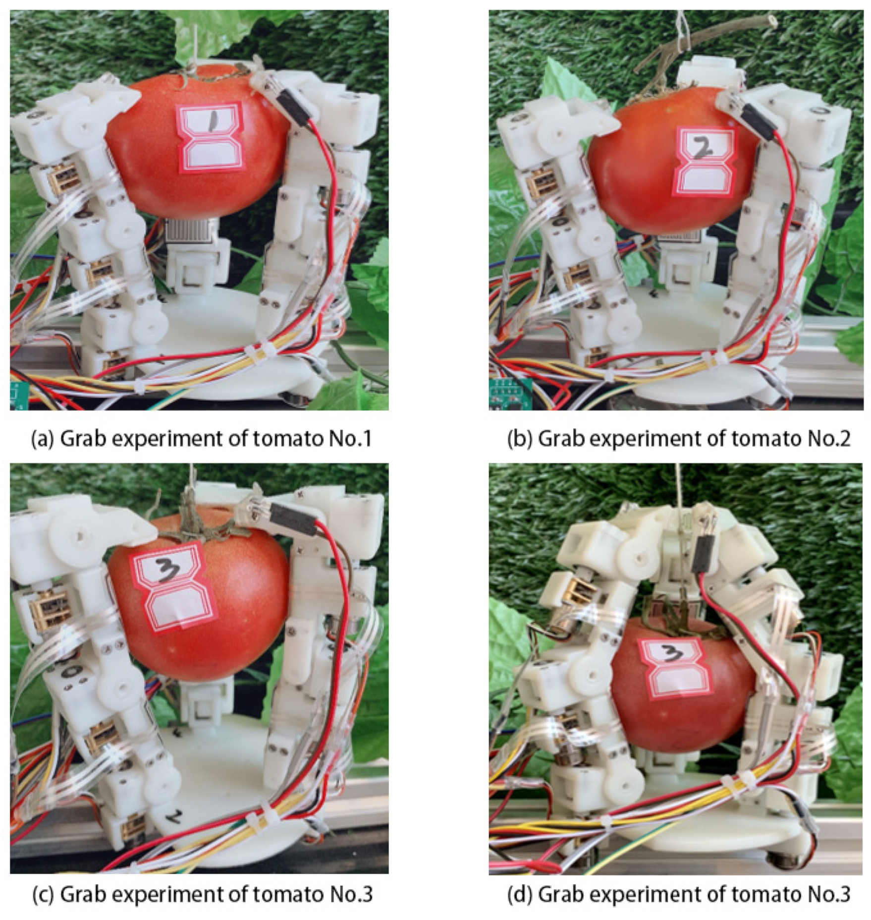
3.2. Test and Result Analysis

Our tomato picking end-effector was used to carry out tomato gripping tests at the experimental station of Northwest Agriculture and Forestry University in Meixian, Shaanxi Province, China (34°07′22.53″ N, 107°59′50″ E, approximately 648 m above sea level) to verify its performance. Three hundred varieties of JP513 tomatoes with different sizes and weights were selected and divided into three groups according to large, medium and small, with corresponding numbers of 1, 2 and 3. The average size and weight of each group are shown in Table 4. Based on the hybrid force/position control strategy proposed in Section 2, the end-effector was used to carry out multiple grasping operations on three tomatoes and to detect the damage degree and damage rate of the tomatoes after the test. During the whole experiment, in order to verify the superiority of the developed end-effector, we also selected tomatoes with irregular sizes as experimental grabbing objects, such as small tomato fruits that could not be touched by three fingers at the same time during grabbing. Based on grabbing the fruit, we verified the structural rationality and the feasibility of the material selection of the developed end-effector. The results are shown in Figure 24.
The results of the small fruit grasping test are shown in Figure 24. Figure 24a–c shows that when grasping tomatoes with a large diameter greater than 60 mm, grasping was achieved through the middle finger in conjunction with the fingertip. Figure 24d shows that when the tomato diameter was less than 50 mm, grasping was performed with the base finger in conjunction with the middle finger. After the picking operation was completed, no damage to the tomato fruit occurred, i.e., the damage rate was zero. Therefore, the above tests demonstrated that the tomato picking end-effector designed in this paper can be used for nondestructive picking of tomatoes of different sizes and weights based on the hybrid force/position control strategy proposed in Section 2.

4. Discussion

This paper analyzed and compared tomato picking end-effectors developed by experts in the field, summarized the strengths and weaknesses of related research and then presented design requirements for a highly flexible and cost-effective tomato picking end-effector. Specifically, in the structural design of the end-effector, a three-finger prototype with nine degrees of freedom was designed based on the structure of the human hand and the length of the middle finger joint, and a stepper motor was selected as the power source for the end-effector test prototype. Since ellipsoidal fitting of the tomatoes was subject to errors and did not accurately drive each joint into contact with the tomato, the exact joint rotation angles needed to be adjusted according to the force feedback control strategy proposed later. The structural design of this end-effector offers the advantages of high flexibility, low cost and structural simplicity, and meets the design requirements for a tomato picking end-effector. In the control section, the paper first presented a forward and inverse kinematic analysis based on the structure of the end-effector; then, a hybrid force/position control strategy was proposed to reduce the damage to the tomatoes during the picking process; second, to enable farmers to adjust the grasping pose of the end-effector by themselves, the end-effector controller and remote wireless debugging module were designed to improve the grasping adaptability and ease of use. Finally, based on the control requirements of picking operations, a control system was designed to achieve real-time control. In the test section, tomatoes of different sizes and qualities were selected for testing to verify the effectiveness of the end-effector for tomato picking. Even with these advancements, the following three aspects of the end-effector were found to be deficient and thus need further investigation and improvement:
  • Flexible joints could be added for the finger structure of the tomato picking end-effector. A suitable integrated driven joint motor could be selected to improve the compactness of the end-effector structure, yielding more of a bionic shape, size and movement.
  • More accurate pressure sensors for contact force collection and more sensors on the end-effector, such as tactile sensors, joint displacement sensors, joint torque sensors, etc., could render the end-effector capable of humanoid picking in the greenhouse environment.
  • The control algorithm of the end-effector could be optimized to equip the end-effector with multiple picking modes while also improving the picking efficiency and enhancing the flexibility and stability of the end-effector when grasping. The control system could also be optimized by adding the human–computer interaction interface for the convenience of user debugging.

5. Conclusions

Based on the problems of low grasping adaptability and high manufacturing cost of existing tomato picking end-effectors, this paper designed a tomato picking end-effector with high grasping adaptability and low cost. First, the mechanical structure and size of the tomato picking manipulator were determined based on the operating environment. Since our tomato picking end-effector contains three fingers with the same structure, the single finger of the end-effector was verified via forward and inverse kinematic analysis and simulation based on the established single-finger model D-H coordinate system to simplify analysis. Second, to reduce the damage to tomatoes in picking operations, a hybrid force/position control strategy was proposed, and the control system of the end-effector was designed based on the control requirements of tomato picking. Finally, three tomatoes with different sizes and qualities were selected to test the tomato picking end-effector prototype. Specifically, a contact force feedback control algorithm was used to detect the contact force between the end-effector and the picked tomatoes in real time, to verify the effectiveness of the end-effector. The experimental results show that the tomato picking end-effector designed in this paper can effectively perform nondestructive tomato picking. Therefore, the end-effector offers high practical application value toward fruit-picking automation.

Author Contributions

Formal analysis, F.G., L.L. and Q.C.; project administration, T.W; software, T.W., W.D. and L.Z.; supervision, F.G., L.L. and Q.C.; validation, W.D., L.Z., L.S. and Y.Z.; writing—original draft, T.W.; writing—review and editing, T.W. All authors have read and agreed to the published version of the manuscript.

Funding

This research has received support from the Shaanxi Key Research and Development Program of China (2019NY-171, 2019ZDLNY02-04), National Natural Science Foundation of China (31971805), National Key Research and Development Program of China (2019YFD1002401) and the Innovative Training Program for College Students of Northwest A&F University (no. S202210712640, no. X202210712061). The authors are also grateful to the reviewers for their helpful comments and recommendations, which made the presentation of the paper better.

Institutional Review Board Statement

Not applicable.

Informed Consent Statement

Not applicable.

Data Availability Statement

Not applicable.

Conflicts of Interest

The authors declare no conflict of interest.

References

  1. Xie, H.; He, Y.; Zou, J.; Wu, Q. Analysis of spatiotemporal differences of cultivated land use intensity in Poyang Lake eco-economic zone based on emergy. J. Geogr. Sci. 2016, 26, 1412–1430. [Google Scholar] [CrossRef]
  2. Liu, X.-J.; Yin, B.-Z.; Hu, Z.-H.; Bao, X.-Y.; Wang, Y.-D.; Zhen, W.-C. Physiological response of flag leaf and yield formation of winter wheat under different spring restrictive irrigation regimes in the Haihe Plain, China. J. Integr. Agric. 2021, 20, 2343–2359. [Google Scholar] [CrossRef]
  3. Li, W.; Wu, W.; Wang, H.; Cheng, X.; Chen, H.; Zhou, Z.; Ding, R. Crowd intelligence in AI 2.0 era. Front. Inf. Technol. Electron. Eng. 2017, 18, 15–43. [Google Scholar] [CrossRef] [Green Version]
  4. Su, L.; Liu, R.; Liu, K.; Li, K.; Liu, L.; Shi, Y. Greenhouse Tomato Picking Robot Chassis. Agriculture 2023, 13, 532. [Google Scholar] [CrossRef]
  5. Du, T.; Kang, S.; Yan, B.; Zhang, J. Alternate Furrow Irrigation: A Practical Way to Improve Grape Quality and Water Use Efficiency in Arid Northwest China. J. Integr. Agric. 2013, 12, 509–519. [Google Scholar] [CrossRef]
  6. Wu, C.; Zhang, T. Intelligent Unmanned System: Important Achievements and Applications of the New Generation of Artificial Intelligence. Front. Inf. Technol. Electron. Eng. 2020, 21, 649–654. [Google Scholar] [CrossRef]
  7. Ma, J.; Sun, S.; Rui, H.; Zhang, J. Summary of Academic Research on China Road Building Machinery 2018. J. China Highw. Eng. 2018, 31, 509–519. [Google Scholar]
  8. Bu, L.; Hu, G.; Chen, J. Assessment of Grasp Ability for An End-effecter with Fin-ray Structure. J. Phys. Conf. Ser. 2021, 1865, 032030. [Google Scholar] [CrossRef]
  9. Cao, P.; Wang, T.; Zhai, L.; Niu, S.; Liu, L.; Shi, Y. Design of 6-DOF Tomato Picking Lifting Platform. Agriculture 2022, 12, 1945. [Google Scholar] [CrossRef]
  10. Li, Z.; Yuan, X.; Wang, C. A review on structural development and recognition–localization methods for end-effector of fruit–vegetable picking robots. Int. J. Adv. Robot. Syst. 2022, 19, 17298806221104906. [Google Scholar] [CrossRef]
  11. Gao, J.; Zhang, F.; Zhang, J.; Yuan, T.; Yin, J.; Guo, H.; Yang, C. Development and evaluation of a pneumatic finger-like end-effector for cherry tomato harvesting robot in greenhouse. Comput. Electron. Agric. 2022, 197, 106879. [Google Scholar] [CrossRef]
  12. Chen, Y.; Zhang, Q.; Tian, Q.; Huo, L.; Feng, X. Research status of underwater multi-fingered hand. Robotics 2020, 42, 749–768. [Google Scholar] [CrossRef]
  13. Zhou, Y.; Tang, Y.; Zou, X.; Wu, M.; Tang, W.; Meng, F.; Zhang, Y.; Kang, H. Adaptive Active Positioning of Camellia oleifera Fruit Picking Points: Classical Image Processing and YOLOv7 Fusion Algorithm. Appl. Sci. 2022, 12, 12959. [Google Scholar] [CrossRef]
  14. Carreon, A.; Baltazar, A.; Treesatayapun, C. Development of a model-free force controller for soft contact of an ultrasonic test probe. Int. J. Adv. Manuf. Technol. 2017, 90, 2839–2847. [Google Scholar] [CrossRef]
  15. Das, P.S.; Chhetry, A.; Maharjan, P.; Rasel, M.S.; Park, J.Y. A laser ablated graphene-based flexible self-powered pressure sensor for human gestures and finger pulse monitoring. Nano Res. 2019, 12, 1789–1795. [Google Scholar] [CrossRef]
  16. Ji, W.; Tang, C.; Xu, B.; He, G. Contact force modeling and variable damping impedance control of apple harvesting robot. Comput. Electron. Agric. 2022, 198, 107026. [Google Scholar] [CrossRef]
  17. Zhang, K.; Lammers, K.; Chu, P.; Li, Z.; Lu, R. System design and control of an apple harvesting robot. Mechatronics 2021, 79, 102644. [Google Scholar] [CrossRef]
  18. Yozo, F.; Siringoringo, D.M.; Yoshiki, I.; Nagayama, T.; Mizutani, T. Summary of research and implementation of monitoring of bridges and building structures in Japan. Engineering 2019, 5, 1093–1119. [Google Scholar]
  19. Zhang, Y.; Chen, Y.; Song, Y.; Zhang, R.; Wang, X. Finding the lowest damage picking mode for tomatoes based on finite element analysis. Comput. Electron. Agric. 2023, 204, 107536. [Google Scholar] [CrossRef]
  20. Lu, W.; Wang, X.; Wang, F. Design and implementation of micro root morphology in situ collection system for tomato and pepper. J. Agric. Eng. 2018, 34, 12–18. [Google Scholar]
  21. Chen, B.; Hu, G.; Liu, W.; Sun, S.; Sun, C.; Xiao, M. Study on the mechanism of automatic vegetable transplanter to alternately pick and drop seedlings from the opposite trays. J. Agric. Mach. 2022, 53, 131–139+151. [Google Scholar]
  22. Zhang, B.; Guo, W.; Wang, Y.; Liu, X. Children’s mouse shape design based on key points. J. Mech. Eng. 2012, 48, 158–163. [Google Scholar] [CrossRef]
  23. Huang, Y.; Lu, R.; Qi, C.; Chen, K. Study on tomato maturity discrimination method based on spatial resolution spectrum. Spectrosc. Spectr. Anal. 2018, 38, 2183–2188. [Google Scholar]
  24. Huang, J.; Lian, F.; Wang, Z.; Sun, S.; Li, M.; Zhang, D.; Cai, X.; Ma, G.; Mai, Z.; Shen, A.; et al. Superconductivity research and performance regulation of two-dimensional van der Waals materials. J. Phys. 2022, 71, 299–317. [Google Scholar]
  25. Sun, Q.; Li, N.; Duan, Y.; Li, H.; Tang, H. Interpretation method of formation dip while drilling based on short-term and short-term memory neural network. Pet. Explor. Dev. 2021, 48, 843–850. [Google Scholar] [CrossRef]
  26. Zhang, Z.; Yao, Y.; Shi, Z.; Wang, H.; Qiao, Z.; Wang, S.; Qin, L.; Du, S.; Luo, F.; Liu, W. Potential field boundary recognition method based on deep learning. J. Geophys. 2022, 65, 1785–1801. [Google Scholar]
  27. Li, G.; Tan, X.; Xiao, F.; Yi, J.; Xue, C.; Yu, Q. Robot inverse kinematics solution based on improved fitness function combination method. J. Agric. Mach. 2022, 53, 436–445. [Google Scholar]
  28. Xiao, Y.; Zhu, C.; Li, W.; Han, K. A new high-order continuous point-to-point motion trajectory planning algorithm. J. Harbin Inst. Technol. 2021, 53, 135–143. [Google Scholar]
  29. Zhang, L.; Ma, Y.; Shan, J.; Xie, A. Dynamic optimization design of a 4-DOF local closed-chain palletizing robot. J. Agric. Mach. 2013, 44, 336–341. [Google Scholar]
Figure 1. Flow of the hybrid force/position control strategy.
Agronomy 13 00947 g001
Figure 2. Ellipsoidal 3D contour and its correspondence in tomato.
Agronomy 13 00947 g002
Figure 3. Contact force control flow.
Agronomy 13 00947 g003
Figure 4. Schematic diagram of force analysis for grasping with a single finger.
Agronomy 13 00947 g004
Figure 5. Tomato bounding and grabbing process.
Agronomy 13 00947 g005
Figure 6. Assembly diagram of tomato picking manipulator.
Agronomy 13 00947 g006
Figure 7. Tomato picking end-effector control system.
Agronomy 13 00947 g007
Figure 8. Results of joint finite element analysis.
Agronomy 13 00947 g008
Figure 9. Motion simulation load.
Agronomy 13 00947 g009
Figure 10. The output curve of motor torque.
Agronomy 13 00947 g010
Figure 11. D-H coordinate system diagram.
Agronomy 13 00947 g011
Figure 12. D-H coordinate system of the single-finger model.
Agronomy 13 00947 g012
Figure 13. Simulation results of the single-finger model.
Agronomy 13 00947 g013aAgronomy 13 00947 g013b
Figure 14. Angle, angular velocity and angular acceleration of joint 1.
Agronomy 13 00947 g014
Figure 15. Angle, angular velocity and angular acceleration of joint 2.
Agronomy 13 00947 g015
Figure 16. Angle, angular velocity and angular acceleration of joint 3.
Agronomy 13 00947 g016
Figure 17. Single-finger model workspace.
Agronomy 13 00947 g017
Figure 18. D-H coordinate system of the whole hand.
Agronomy 13 00947 g018
Figure 19. Three-dimensional workspace of fingertips in the coordinate system of the palm.
Agronomy 13 00947 g019
Figure 20. Physical view of tomato picking end-effector.
Agronomy 13 00947 g020
Figure 21. Control architecture of the tomato picking end-effector.
Agronomy 13 00947 g021
Figure 22. Operation flow of the end-effector joint motor.
Agronomy 13 00947 g022
Figure 23. Software flow of the remote wireless debugging module.
Agronomy 13 00947 g023
Figure 24. End-effector test diagram.
Agronomy 13 00947 g024
Table 1. Experimental data and calculation results for joint rotation angle.
Serial Number θ 1 / ° θ 2 / ° θ 3 / ° xyz
1000160.00000
235206066.6590119.81600
320304094.9488106.48390
440102098.2107122.11760
Table 2. Inverse kinematic verification data.
Given AngleForward Kinematics/mmInverse Kinematics/°Inverse Kinematics/mm
θ 1 θ 2 θ 3 xyz θ 1 θ 2 θ 3 xyz
000160.0000000160.0000
35206066.659119.816035.00020.00060.00066.659119.81600
20304094.949106.484020.00030.00040.00094.949106.4840
40102098.211122.117039.99910.00019.99998.211122.1180
Table 3. D-H parameters for finger base coordinates to palm base coordinates.
Parameter d i 0 θ i 0 α i 0 a i 0
Z100−120°90°40
Z200120°90°40
Z30090°40
Table 4. Experimental tomato data.
NumberLarge Diameter/mmSmall Diameter/mmHeight/mmWeight/g
182.475.266.7230
268.265.456.5189
358.956.152.6128
Disclaimer/Publisher’s Note: The statements, opinions and data contained in all publications are solely those of the individual author(s) and contributor(s) and not of MDPI and/or the editor(s). MDPI and/or the editor(s) disclaim responsibility for any injury to people or property resulting from any ideas, methods, instructions or products referred to in the content.

